EP0859948B1 - Bearing and monitoring system for bearings - Google Patents
Bearing and monitoring system for bearings Download PDFInfo
- Publication number
- EP0859948B1 EP0859948B1 EP19960938804 EP96938804A EP0859948B1 EP 0859948 B1 EP0859948 B1 EP 0859948B1 EP 19960938804 EP19960938804 EP 19960938804 EP 96938804 A EP96938804 A EP 96938804A EP 0859948 B1 EP0859948 B1 EP 0859948B1
- Authority
- EP
- European Patent Office
- Prior art keywords
- bearing
- local transmitter
- sensor
- status information
- information
- Prior art date
- Legal status (The legal status is an assumption and is not a legal conclusion. Google has not performed a legal analysis and makes no representation as to the accuracy of the status listed.)
- Expired - Lifetime
Links
Images

Classifications
-
- G—PHYSICS
- G01—MEASURING; TESTING
- G01M—TESTING STATIC OR DYNAMIC BALANCE OF MACHINES OR STRUCTURES; TESTING OF STRUCTURES OR APPARATUS, NOT OTHERWISE PROVIDED FOR
- G01M13/00—Testing of machine parts
- G01M13/04—Bearings
- G01M13/045—Acoustic or vibration analysis
-
- F—MECHANICAL ENGINEERING; LIGHTING; HEATING; WEAPONS; BLASTING
- F16—ENGINEERING ELEMENTS AND UNITS; GENERAL MEASURES FOR PRODUCING AND MAINTAINING EFFECTIVE FUNCTIONING OF MACHINES OR INSTALLATIONS; THERMAL INSULATION IN GENERAL
- F16C—SHAFTS; FLEXIBLE SHAFTS; ELEMENTS OR CRANKSHAFT MECHANISMS; ROTARY BODIES OTHER THAN GEARING ELEMENTS; BEARINGS
- F16C19/00—Bearings with rolling contact, for exclusively rotary movement
- F16C19/52—Bearings with rolling contact, for exclusively rotary movement with devices affected by abnormal or undesired conditions
-
- F—MECHANICAL ENGINEERING; LIGHTING; HEATING; WEAPONS; BLASTING
- F16—ENGINEERING ELEMENTS AND UNITS; GENERAL MEASURES FOR PRODUCING AND MAINTAINING EFFECTIVE FUNCTIONING OF MACHINES OR INSTALLATIONS; THERMAL INSULATION IN GENERAL
- F16C—SHAFTS; FLEXIBLE SHAFTS; ELEMENTS OR CRANKSHAFT MECHANISMS; ROTARY BODIES OTHER THAN GEARING ELEMENTS; BEARINGS
- F16C35/00—Rigid support of bearing units; Housings, e.g. caps, covers
- F16C35/04—Rigid support of bearing units; Housings, e.g. caps, covers in the case of ball or roller bearings
- F16C35/042—Housings for rolling element bearings for rotary movement
- F16C35/047—Housings for rolling element bearings for rotary movement with a base plate substantially parallel to the axis of rotation, e.g. horizontally mounted pillow blocks
-
- F—MECHANICAL ENGINEERING; LIGHTING; HEATING; WEAPONS; BLASTING
- F16—ENGINEERING ELEMENTS AND UNITS; GENERAL MEASURES FOR PRODUCING AND MAINTAINING EFFECTIVE FUNCTIONING OF MACHINES OR INSTALLATIONS; THERMAL INSULATION IN GENERAL
- F16C—SHAFTS; FLEXIBLE SHAFTS; ELEMENTS OR CRANKSHAFT MECHANISMS; ROTARY BODIES OTHER THAN GEARING ELEMENTS; BEARINGS
- F16C2233/00—Monitoring condition, e.g. temperature, load, vibration
Definitions
- the present invention relates to a bearing apparatus and a system for monitoring status information regarding the operation of bearings.
- each mechanical component may be equipped with a plurality of sensors.
- the signal information provided by the various sensors of many mechanical components may be processed at a central monitoring controller.
- dedicated transmission lines have typically been provided for each of these sensors.
- several transmission lines would generally extend between each of the mechanical components and the central monitoring facility.
- the present invention provides a system for monitoring a plurality of bearing units in a single facility, said system comprising:
- Each of the local transmitters may have a unique electronic identifier associated therewith to facilitate communication with the central monitoring processor.
- the central monitoring processor functions to sequentially interrogate the local transmitters via the respective electronic identifiers.
- a bus line interconnects the plurality of local transmitters and the central monitoring processor to provide electrical communication therebetween.
- the bus line may include a main trunk and a plurality of branch lines, wherein the respective local transmitters are connected to the branch lines.
- the invention also provides a bearing apparatus for facilitating rotation of a shaft, said bearing apparatus comprising:
- the local transmitter includes a printed circuit card having various components mounted thereon.
- the printed circuit card may be fixedly connected to the bearing housing, such as by being potted in a cover attached thereto.
- the accelerometer may be of the type incorporated into a microchip and directly mounted onto the printed circuit card.
- the invention further provides a method of monitoring a plurality of bearing units in operation in a single facility, said method comprising the steps of:
- the local transmitter functions to convert the sensor information to a predetermined format, which may be supplied from the local transmitter as the status information.
- the local transmitter may perform at least an initial analysis of the sensor information, whereby the status information represents a processing of the sensor information.
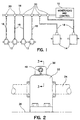
- FIG. 1 An exemplary embodiment of a mechanical component monitoring system is diagrammatically illustrated in Figure 1.
- the system includes a processor 10 which provides monitoring and control functions for an indeterminate number of mechanical components.
- processor 10 may utilize information received from the respective mechanical components to provide diagnostic information.
- This diagnostic information can be obtained using such techniques as Fast Fourier Transform (FFT), trend line analysis or other suitable analysis techniques.
- FFT Fast Fourier Transform
- such mechanical components include a plurality of bearing assemblies 12 along with several speed reducers 14.
- Bearings 12 and speed reducers 14 each include a plurality of sensor devices in electrical communication with a respective local transmitter.
- the local transmitter provides status information regarding operation of the associated mechanical component to processor 10 in a predetermined format.
- such information is transmitted to processor 10 as a serial digital word, in which portions of the word may be dedicated to information received from specific sensors.
- each of the local transmitters has a unique electronic identifier, or "address.”
- processor 10 may "interrogate” a particular local transmitter using this unique identifier.
- the local transmitter may responsively provide status information regarding the associated mechanical component.
- processor 10 will interrogate the various local transmitters of the system according to a predetermined sequence.
- electrical communication between the local transmitters and processor 10 is accomplished utilizing a bus structure having a main trunk 16 and a plurality of branch lines 18.
- Branch lines 18 are respectively connected to the bearings 12 and speed reducers 14, as shown. Connection between branch lines 18 and main trunk 16 is facilitated by a plurality of T-couplings 20.
- the principles of the present invention are also applicable to arrangements which do not utilize a "hard-wired" bus.
- the invention contemplates arrangements whereby the local transmitters provide status information to processor 10 via some form of telemetry, such as radio or infrared communication.
- FIGS 2 and 3 illustrate the construction of a bearing apparatus such as bearings 12 of Figure 1.
- the bearing apparatus includes a housing 22 having a bearing assembly therein for rotatably supporting a shaft 24.
- housing 22 is configured as a pillow block housing mounted to a stationary surface 26. It should be appreciated, however, that other suitable housing configurations, such as flange housings, may also be utilized.
- the bearing assembly located within housing 22 includes an annular inner ring 28 appropriately secured to shaft 12.
- Inner ring 28 defines an inner raceway about its outer circumferential surface.
- An annular outer ring 30 is further provided having an outer raceway situated in opposition to the inner raceway.
- a plurality of bearing elements, such as roller bearings 32, are disposed between the inner raceway and the outer raceway to facilitate relative rotation between ring members 28 and 30. While roller bearings are illustrated, it should be appreciated that other suitable types of bearing elements, such as ball bearings, may also be utilized for this purpose.
- the local transmitter may be constructed as a single printed circuit card 34 having various components mounted thereon.
- a cover 36 in this case a small housing, may be provided to protect card 34 during use.
- card 34 is "potted" within cover 36 to provide an even greater degree of protection.
- card 34 may actually be embedded within an epoxy 38 or other suitable polymeric compound which fills the inner cavity of cover 36.
- Cover 36 may be attached to the exterior of housing 22 by bolts 40, or other suitable attachment means.
- the bearing apparatus in this case includes a speed sensor 42, a temperature sensor 44 and an accelerometer 46.
- Each of these sensors is preferably located within housing 22 or under cover 36 to provide a relatively compact arrangement, as shown.
- the sensors communicate with card 34 via respective signal lines extending therebetween.
- various other sensors may also be utilized, which communicate with card 34 via the respective signal lines collectively indicated at 48.
- speed sensor 42 may be an inductive sensor operative to sense variations in its inductance produced during rotation of inner ring 28.
- a nut or clamping collar used to secure inner ring 28 to shaft 24 may also function as a detection element from which sensor 42 can read.
- temperature sensor 44 may be configured as a thermocouple sensor located within a receiving bore defined in housing 22.
- thermocouple sensor located within a receiving bore defined in housing 22. The construction of such a sensor is described in detail in U.S. Patent No. 5,433,525, issued July 18, 1995 to the present inventor, incorporated herein by reference.
- accelerometer 46 may be of a commercially available type constructed as a separate unit. This unit, like card 34, may be potted within cover 36 for protection. Accelerometer 46 contains a movable mass responsive to vibratory movement of housing 22 to produce an analogous output signal. As such, vibration of the bearing apparatus can be detected.
- One suitable accelerometer for this purpose is Model No. 327MII, marketed by IMI of Depew, New York.
- circuitry located on card 34 receives sensor information and subsequently provides status information to the external processor.
- the status information may be transmitted in a serial digital format, in which portions of a digital word correspond to the respective sensors.
- the status information may represent actual sensor information.
- a digital word sixty-four (64) bits in length.
- eight (8) bits may be respectively dedicated to information from each of speed sensor 42, temperature sensor 44 and accelerometer 46.
- the remainder of the word will be used for identification and communication protocol and checking of the transmission.
- the local transmitter may perform at least an initial analysis of the sensor information.
- the status information would represent a processed version of the sensor information.
- the local processor may perform an FFT on the sensor information to provide some form of diagnostic data to the central processor.
- Other suitable analysis techniques such as trend line analysis, may also be utilized for this purpose.
- Card 34 provides the digital word containing the status information to a local port 49.
- branch line 18 is connected to port 49, thus establishing electrical communication with processor 10.
- port 49 is a five (5) pin port, corresponding to the five (5) lines comprising the overall bus.
- port 49 is configured such that branch line 18 may be easily connected or disconnected as desired.
- two of the five (5) lines in the bus serve to transmit signal information between card 34 and processor 10.
- Presently preferred embodiments utilize the controller area network (CAN) protocol for this purpose because it generally allows longer distance transmission than some other protocols, such as RS-232.
- Two other lines provide operating voltage for the circuit components, e.g, floating +24 VDC in the illustrated embodiment.
- the fifth line provides case grounding (GND).
- Card 34 includes an on-board microprocessor 50 to recognize the external interrogation and provide the desired serial output.
- the output of some sensors, such as speed sensor 42, may be provided directly to microprocessor 50.
- A/D analog-to-digital
- the outputs of temperature sensor 44 and accelerometer 46 are in this case provided to respective A/D converters 52 and 54.
- Converters 52 and 54 supply a representative digital output to microprocessor 50. It should be appreciated, however, that some suitable microprocessors may have one or more internal A/D converters.
- Typical accelerometer devices such as accelerometer 46, often utilize an external power supply circuit.
- this supply circuit may be mounted directly on card 34, as indicated at 56.
- the accelerometer itself may be mounted on card 34 in some alternative embodiments.
- accelerometers have recently been developed which are incorporated into a microchip. Such a "micromachine" accelerometer is diagrammatically indicated at 58.
- sensors which may be connected to microprocessor 50 provide an on/off output.
- the devices are configured to change state (from either a normally open or a normally closed state) when the parameter of interest exceeds a predetermined threshold.
- Examples of such sensors include temperature switch 60 and proximity switch 62.
- a preferred arrangement of temperature switch 60 is shown in U.S. Patent No. 5,439,296, issued August 8, 1995 to the present inventor and incorporated herein by reference.
- pressure switch 64 Another sensor which provides an on/off signal is pressure switch 64.
- pressure switch 64 would not be utilized with a bearing, but may be incorporated into a speed reducer.
- Pressure switch 64 will function to detect when the pressure inside the reducer exceeds a predetermined value, which signals that the breather is plugged.
Landscapes
- Engineering & Computer Science (AREA)
- General Engineering & Computer Science (AREA)
- Mechanical Engineering (AREA)
- Physics & Mathematics (AREA)
- Acoustics & Sound (AREA)
- General Physics & Mathematics (AREA)
- Arrangements For Transmission Of Measured Signals (AREA)
- Rolling Contact Bearings (AREA)
- Testing Of Devices, Machine Parts, Or Other Structures Thereof (AREA)
- Medicines Containing Antibodies Or Antigens For Use As Internal Diagnostic Agents (AREA)
Description
- The present invention relates to a bearing apparatus and a system for monitoring status information regarding the operation of bearings.
- The various types of machinery generally found in an industrial setting will often utilize many bearings, speed reducers or other such mechanical components. For example, a single conveyor will frequently be equipped with multiple pillow block or flange bearings to support its various rotatable shafts. Speed reducers or other gear boxes may be utilized to transmit mechanical power to the machinery from a suitable prime mover.
- The status of these mechanical components is often monitored during operation to determine when some form of corrective action should be taken. For example, the temperature of a bearing can be monitored to lessen the occurrence of overheating. It is also frequently desirable to monitor the rotational speed of the shaft to which the bearing is attached, as well as the extent to which the bearing housing is experiencing undesirable vibration. To facilitate such monitoring, each mechanical component may be equipped with a plurality of sensors.
- The signal information provided by the various sensors of many mechanical components may be processed at a central monitoring controller. In the past, however, dedicated transmission lines have typically been provided for each of these sensors. As a result, several transmission lines would generally extend between each of the mechanical components and the central monitoring facility.
- Due to the number of mechanical components in a typical industrial facility, the number of transmission lines carrying signal information to the central monitoring controller can become quite large. Thus, it will be appreciated that this type of arrangement will often be complex and cumbersome.
- Known monitoring systems for bearings are described in Technisches Messen, vol. 57, no. 1, January 1990, München, DE, pages 18-22 (XP000094585), Herrmann: "Gleitlagerüberwachung durch einfache Messung von Thermospannungen", and Patent Abstracts of Japan, vol. 14, no. 94 (P-1010) 21 February 1990 & JP-A-01 301 131.
- The present invention provides a system for monitoring a plurality of bearing units in a single facility, said system comprising:
- a plurality of bearing units to be monitored, each bearing unit thereof including multiple sensor devices, each for detecting a respective different selected sensor information;
- a plurality of local transmitters respectively associated with said plurality of bearing units, a respective local transmitter thereof being in electrical communication with said sensor devices of an associated bearing unit to receive said selected sensor information, each said local transmitter including a local port having a predetermined connector configuration; and
- a central monitoring processor in selective electrical communication with each said respective local transmitter such that selected status information regarding said associated bearing unit will be supplied to said central monitoring processor at predetermined times.
-
- Each of the local transmitters may have a unique electronic identifier associated therewith to facilitate communication with the central monitoring processor. In an exemplary construction, the central monitoring processor functions to sequentially interrogate the local transmitters via the respective electronic identifiers.
- In presently preferred embodiments, a bus line interconnects the plurality of local transmitters and the central monitoring processor to provide electrical communication therebetween. Preferably, the bus line may include a main trunk and a plurality of branch lines, wherein the respective local transmitters are connected to the branch lines.
- The invention also provides a bearing apparatus for facilitating rotation of a shaft, said bearing apparatus comprising:
- a bearing housing;
- a bearing assembly contained in said housing and including respective annular members capable of relative rotation, one of said annular members operatively rotating with said shaft;
- multiple sensor devices mounted proximate said housing, each of said multiple sensor devices being for detecting a respective different type of sensor information regarding said bearing apparatus; and
- a local transmitter having an output port, said local transmitter being in electrical communication with said multiple sensor devices to receive said sensor information therefrom and subsequently providing selected status information at said output port in a predetermined format.
-
- In presently preferred embodiments, the local transmitter includes a printed circuit card having various components mounted thereon. The printed circuit card may be fixedly connected to the bearing housing, such as by being potted in a cover attached thereto. In this case, the accelerometer may be of the type incorporated into a microchip and directly mounted onto the printed circuit card.
- The invention further provides a method of monitoring a plurality of bearing units in operation in a single facility, said method comprising the steps of:
- (a) providing a plurality of said bearing units to be monitored, each said bearing unit thereof including multiple sensor devices each operative to detect a different type of selected status information;
- (b) providing for each said bearing unit a respective local transmitter in electrical communication with said multiple sensor devices;
- (c) sampling, with said local transmitter, selected sensor information as detected by said multiple sensor devices;
- (d) producing, with said local transmitter, selected status information based on said selected sensor information;
- (e) electronically interrogating each said local transmitter to request said selected status information; and
- (f) responsively supplying said selected status information from said local transmitter.
-
- In some embodiments, the local transmitter functions to convert the sensor information to a predetermined format, which may be supplied from the local transmitter as the status information. In other embodiments, the local transmitter may perform at least an initial analysis of the sensor information, whereby the status information represents a processing of the sensor information.
- Other objects, features and aspects of the present invention are provided by various combinations and subcombinations of the disclosed elements, which are discussed in greater detail below.
- A full and enabling disclosure of the present invention, including the best mode thereof, to one of ordinary skill in the art is set forth more particularly in the remainder of the specification, including reference to the accompanying drawings, in which:
- Figure 1 is a diagrammatic representation of a mechanical component monitoring system constructed in accordance with the invention;
- Figure 2 is a side elevation of a bearing apparatus constructed in accordance with the present invention;
- Figure 3 is a partial cross sectional view as taken along lines 3-3 of Figure 2; and
- Figure 4 is a diagrammatic representation illustrating a local transmitter of the present invention as connected to a variety of sensor devices.
-
- Repeat use of reference characters in the present specification and drawings is intended to represent same or analogous features or elements of the invention.
- It is to be understood by one of ordinary skill in the art that the present discussion is a description of exemplary embodiments only, and is not intended as limiting broader aspects of the present invention, which broader aspects are embodied in the exemplary constructions.
- An exemplary embodiment of a mechanical component monitoring system is diagrammatically illustrated in Figure 1. As can be seen, the system includes a
processor 10 which provides monitoring and control functions for an indeterminate number of mechanical components. For example,processor 10 may utilize information received from the respective mechanical components to provide diagnostic information. This diagnostic information can be obtained using such techniques as Fast Fourier Transform (FFT), trend line analysis or other suitable analysis techniques. - In this case, such mechanical components include a plurality of
bearing assemblies 12 along withseveral speed reducers 14.Bearings 12 andspeed reducers 14 each include a plurality of sensor devices in electrical communication with a respective local transmitter. The local transmitter provides status information regarding operation of the associated mechanical component toprocessor 10 in a predetermined format. In presently preferred embodiments, such information is transmitted toprocessor 10 as a serial digital word, in which portions of the word may be dedicated to information received from specific sensors. - Preferably, each of the local transmitters has a unique electronic identifier, or "address." As such,
processor 10 may "interrogate" a particular local transmitter using this unique identifier. When interrogated in this manner, the local transmitter may responsively provide status information regarding the associated mechanical component. Preferably,processor 10 will interrogate the various local transmitters of the system according to a predetermined sequence. - In the illustrated embodiment, electrical communication between the local transmitters and
processor 10 is accomplished utilizing a bus structure having amain trunk 16 and a plurality ofbranch lines 18.Branch lines 18 are respectively connected to thebearings 12 andspeed reducers 14, as shown. Connection betweenbranch lines 18 andmain trunk 16 is facilitated by a plurality of T-couplings 20. - As discussed above, prior art arrangements often utilized a dedicated transmission line for each sensor associated with a particular mechanical component. As the number of mechanical components increased, the number of total lines also increased on a proportionate basis. In the illustrated embodiment, however, more mechanical devices can be added to the system by simply providing
additional branch lines 18. Thus, the construction disclosed herein allows information to be provided toprocessor 10 in a manner which is more convenient and efficient. - It should be appreciated that the principles of the present invention are also applicable to arrangements which do not utilize a "hard-wired" bus. For example, the invention contemplates arrangements whereby the local transmitters provide status information to
processor 10 via some form of telemetry, such as radio or infrared communication. - Figures 2 and 3 illustrate the construction of a bearing apparatus such as
bearings 12 of Figure 1. As can be seen, the bearing apparatus includes ahousing 22 having a bearing assembly therein for rotatably supporting ashaft 24. In this case,housing 22 is configured as a pillow block housing mounted to astationary surface 26. It should be appreciated, however, that other suitable housing configurations, such as flange housings, may also be utilized. - Referring now particularly to Figure 3, the bearing assembly located within
housing 22 includes an annularinner ring 28 appropriately secured toshaft 12.Inner ring 28 defines an inner raceway about its outer circumferential surface. An annularouter ring 30 is further provided having an outer raceway situated in opposition to the inner raceway. A plurality of bearing elements, such asroller bearings 32, are disposed between the inner raceway and the outer raceway to facilitate relative rotation betweenring members - Depending on the exigencies of a particular situation, various techniques may be utilized to effect securement of
inner ring member 28 toshaft 12. Among the arrangements which may be utilized for this purpose are various tapered adapter arrangements, set screw arrangements, eccentric collar clamping arrangements, and arrangements utilizing a slotted clamping collar situated about a plurality of clamping fingers. - The local transmitter may be constructed as a single printed
circuit card 34 having various components mounted thereon. Acover 36, in this case a small housing, may be provided to protectcard 34 during use. In some exemplary embodiments,card 34 is "potted" withincover 36 to provide an even greater degree of protection. In other words,card 34 may actually be embedded within an epoxy 38 or other suitable polymeric compound which fills the inner cavity ofcover 36.Cover 36 may be attached to the exterior ofhousing 22 bybolts 40, or other suitable attachment means. - As can be seen in Figure 3, the bearing apparatus in this case includes a
speed sensor 42, atemperature sensor 44 and anaccelerometer 46. Each of these sensors is preferably located withinhousing 22 or undercover 36 to provide a relatively compact arrangement, as shown. The sensors communicate withcard 34 via respective signal lines extending therebetween. Depending on the requirements of a particular application, various other sensors may also be utilized, which communicate withcard 34 via the respective signal lines collectively indicated at 48. - As shown,
speed sensor 42 may be an inductive sensor operative to sense variations in its inductance produced during rotation ofinner ring 28. In an exemplary construction, a nut or clamping collar used to secureinner ring 28 toshaft 24 may also function as a detection element from whichsensor 42 can read. - As shown,
temperature sensor 44 may be configured as a thermocouple sensor located within a receiving bore defined inhousing 22. The construction of such a sensor is described in detail in U.S. Patent No. 5,433,525, issued July 18, 1995 to the present inventor, incorporated herein by reference. - In the illustrated embodiment,
accelerometer 46 may be of a commercially available type constructed as a separate unit. This unit, likecard 34, may be potted withincover 36 for protection.Accelerometer 46 contains a movable mass responsive to vibratory movement ofhousing 22 to produce an analogous output signal. As such, vibration of the bearing apparatus can be detected. One suitable accelerometer for this purpose is Model No. 327MII, marketed by IMI of Depew, New York. - As described above, circuitry located on
card 34 receives sensor information and subsequently provides status information to the external processor. The status information may be transmitted in a serial digital format, in which portions of a digital word correspond to the respective sensors. In some embodiments, the status information may represent actual sensor information. - For example, consider a digital word sixty-four (64) bits in length. In this case, eight (8) bits may be respectively dedicated to information from each of
speed sensor 42,temperature sensor 44 andaccelerometer 46. The remainder of the word will be used for identification and communication protocol and checking of the transmission. - In other embodiments, the local transmitter may perform at least an initial analysis of the sensor information. In this case, the status information would represent a processed version of the sensor information. As an example, the local processor may perform an FFT on the sensor information to provide some form of diagnostic data to the central processor. Other suitable analysis techniques, such as trend line analysis, may also be utilized for this purpose.
-
Card 34 provides the digital word containing the status information to alocal port 49. As shown,branch line 18 is connected to port 49, thus establishing electrical communication withprocessor 10. In the illustrated embodiment,port 49 is a five (5) pin port, corresponding to the five (5) lines comprising the overall bus. Preferably,port 49 is configured such thatbranch line 18 may be easily connected or disconnected as desired. - As can be seen in Figure 4, two of the five (5) lines in the bus serve to transmit signal information between
card 34 andprocessor 10. Presently preferred embodiments utilize the controller area network (CAN) protocol for this purpose because it generally allows longer distance transmission than some other protocols, such as RS-232. Two other lines provide operating voltage for the circuit components, e.g, floating +24 VDC in the illustrated embodiment. The fifth line provides case grounding (GND). -
Card 34 includes an on-board microprocessor 50 to recognize the external interrogation and provide the desired serial output. The output of some sensors, such asspeed sensor 42, may be provided directly tomicroprocessor 50. For other sensors, it may be appropriate to provide a separate analog-to-digital (A/D) converter. For example, the outputs oftemperature sensor 44 andaccelerometer 46 are in this case provided to respective A/D converters Converters microprocessor 50. It should be appreciated, however, that some suitable microprocessors may have one or more internal A/D converters. - Typical accelerometer devices, such as
accelerometer 46, often utilize an external power supply circuit. In accordance with the present invention, this supply circuit may be mounted directly oncard 34, as indicated at 56. In addition, the accelerometer itself may be mounted oncard 34 in some alternative embodiments. Specifically, accelerometers have recently been developed which are incorporated into a microchip. Such a "micromachine" accelerometer is diagrammatically indicated at 58. - Other sensors which may be connected to
microprocessor 50 provide an on/off output. In other words, the devices are configured to change state (from either a normally open or a normally closed state) when the parameter of interest exceeds a predetermined threshold. Examples of such sensors includetemperature switch 60 andproximity switch 62. A preferred arrangement oftemperature switch 60 is shown in U.S. Patent No. 5,439,296, issued August 8, 1995 to the present inventor and incorporated herein by reference. - Another sensor which provides an on/off signal is
pressure switch 64. Generally,pressure switch 64 would not be utilized with a bearing, but may be incorporated into a speed reducer.Pressure switch 64 will function to detect when the pressure inside the reducer exceeds a predetermined value, which signals that the breather is plugged. - While preferred embodiments of the invention have been shown and described, it will be appreciated that modifications and variations may be made thereto by those of ordinary skill in the art without departing from the scope of the appended claims. For example, the term "mechanical components" as used herein can include a variety of mechanical and electromechanical devices, including motors. It will be further appreciated that aspects of the various embodiments may be interchanged both in whole or in part. Additionally, those of ordinary skill in the art will appreciate that the foregoing description is by way of example only, and is not intended to be limitative of the invention so further described in such appended claims.
Claims (27)
- A system for monitoring a plurality of bearing units in a single facility, said system comprising:a plurality of bearing units (12) to be monitored, each bearing unit thereof including multiple sensor devices (42, 44, 46), each for detecting a respective different selected sensor information;a plurality of local transmitters (34) respectively associated with said plurality of bearing units, a respective local transmitter thereof being in electrical communication with said sensor devices of an associated bearing unit to receive said selected sensor information, each said local transmitter including a local port (49) having a predetermined connector configuration; anda central monitoring processor (10) in selective electrical communication with each said respective local transmitter such that selected status information regarding said associated bearing unit will be supplied to said central monitoring processor at predetermined times.
- A system as claimed in claim 1, wherein each said respective local transmitter (34) has a unique electronic identifier associated therewith to facilitate communication with said central monitoring processor (10).
- A system as claimed in claim 2, wherein each said respective local transmitter (34) functions to supply said selected status information to said central monitoring processor (10) via a serial digital format.
- A system as claimed in any one of claims 1 to 3, wherein each of said respective local transmitters (34) functions to send said selected status information to said central monitoring processor (10) according to a predetermined serial protocol.
- A system as claimed in claim 4, wherein a first sensor device of each bearing unit (12) is a shaft speed sensor (42), a second sensor device of that bearing unit is an accelerometer (46), and a third sensor device of that bearing unit is a temperature sensor (44).
- A system as claimed in claim 2, wherein said central monitoring processor (10) functions sequentially to interrogate said respective local transmitters (34) via said unique electronic identifier.
- A system, as claimed in claim 1, further comprising a bus line (16, 18) interconnecting said plurality of local transmitters (34) and said central monitoring processor (10) to provide electrical communication therebetween.
- A system as claimed in claim 7, wherein said bus line includes a main trunk (16) and a plurality of branch lines (18), said plurality of local transmitters (34) being respectively connected to said plurality of branch lines.
- A system as claimed in claim 8, wherein each said respective local transmitter (34) functions to send said selected status information to said central monitoring processor (10) via a serial digital format.
- A system as claimed in claim 1, wherein said plurality of bearing units (12) includes at least one speed reducer apparatus.
- A bearing apparatus for facilitating rotation of a shaft (24), said bearing apparatus comprising:a bearing housing (22);a bearing assembly (12) contained in said housing and including respective annular members (28, 30) capable of relative rotation, one of said annular members operatively rotating with said shaft;multiple sensor devices (42, 44, 46) mounted proximate said housing, each of said multiple sensor devices being for detecting a respective different type of sensor information regarding said bearing apparatus; anda local transmitter (34) having an output port (49), said local transmitter being in electrical communication with said multiple sensor devices to receive said sensor information therefrom and subsequently providing selected status information at said output port in a predetermined format.
- A bearing apparatus as claimed in claim 11, wherein said local transmitter (34) has a unique electronic identifier associated therewith to facilitate communication with an external processor.
- A bearing apparatus as claimed in claim 12, wherein said local transmitter (34) functions to supply said status information from said output port (49) via a serial digital format.
- A bearing apparatus as claimed in claim 13, wherein said status information includes said sensor information as embedded within a serial digital word.
- A bearing apparatus as claimed in claim 14, wherein predetermined portions of said serial digital word represent information received from respective ones of said plurality of sensor devices (42, 44, 46).
- A bearing apparatus as claimed in claim 13, wherein said local transmitter (34) functions to analyse said sensor information and provide processed data within said status information.
- A bearing apparatus as claimed in claim 11, wherein a first of the multiple sensor devices is a shaft speed sensor (42), a second of the multiple sensors devices is an accelerometer (46), and a third of the multiple sensor devices is a temperature sensor (44).
- A bearing apparatus as claimed in claim 11, wherein said local transmitter includes a printed circuit card (34) having various components mounted thereon, said printed circuit card being fixedly connected to said bearing housing (22).
- A bearing apparatus as claimed in claim 18, wherein said printed circuit card (34) is potted in a cover (36) attached to said bearing housing (22).
- A bearing apparatus as claimed in claim 18, wherein said plurality of sensor devices includes an accelerometer (46) mounted on said printed circuit card (34).
- A bearing apparatus as claimed in claim 20, wherein said accelerometer (46) is of the type incorporated into a microchip.
- A method of monitoring a plurality of bearing units (12) in operation in a single facility, said method comprising the steps of:(a) providing a plurality of said bearing units to be monitored, each said bearing unit thereof including multiple sensor devices (42, 44, 46) each operative to detect a different type of selected status information;(b) providing for each said bearing unit a respective local transmitter (34) in electrical communication with said multiple sensor devices;(c) sampling, with said local transmitter, selected sensor information as detected by said multiple sensor devices;(d) producing, with said local transmitter, selected status information based on said selected sensor information;(e) electronically interrogating each said local transmitter to request said selected status information; and(f) responsively supplying said selected status information from said local transmitter.
- A method as claimed in claim 22, wherein step (d) comprises at least in part converting, with said local transmitter (34), said selected sensor information to a predetermined format to produce said selected status information.
- A method as claimed in claim 22, wherein step (d) comprises analysing said selected sensor information to produce said selected status information.
- A method as claimed in claim 22, wherein said selected status information is supplied from said local transmitter (34) in a serial digital format.
- A method as claimed in claim 22, wherein a first of the multiple sensor devices is a shaft speed sensor (42), a second of the multiple sensor devices is an accelerometer (46), and a third of the multiple sensor devices is a temperature sensor (44).
- A method as claimed in claim 22, wherein said local transmitter (34) is electronically interrogated in step (e) utilising a unique electronic identifier pre-assigned thereto.
Applications Claiming Priority (3)
| Application Number | Priority Date | Filing Date | Title |
|---|---|---|---|
| US08/554,182 US6331823B1 (en) | 1995-11-06 | 1995-11-06 | Monitoring system for bearings |
| US554182 | 1995-11-06 | ||
| PCT/US1996/017827 WO1997017599A1 (en) | 1995-11-06 | 1996-11-05 | Monitoring system for bearings or other mechanical components |
Publications (2)
| Publication Number | Publication Date |
|---|---|
| EP0859948A1 EP0859948A1 (en) | 1998-08-26 |
| EP0859948B1 true EP0859948B1 (en) | 2002-08-28 |
Family
ID=24212352
Family Applications (1)
| Application Number | Title | Priority Date | Filing Date |
|---|---|---|---|
| EP19960938804 Expired - Lifetime EP0859948B1 (en) | 1995-11-06 | 1996-11-05 | Bearing and monitoring system for bearings |
Country Status (7)
| Country | Link |
|---|---|
| US (1) | US6331823B1 (en) |
| EP (1) | EP0859948B1 (en) |
| AU (1) | AU726788B2 (en) |
| BR (1) | BR9612343A (en) |
| CA (1) | CA2236717A1 (en) |
| DE (1) | DE69623312T2 (en) |
| WO (1) | WO1997017599A1 (en) |
Cited By (1)
| Publication number | Priority date | Publication date | Assignee | Title |
|---|---|---|---|---|
| WO2016134391A1 (en) | 2015-02-24 | 2016-09-01 | Radicos Technologies Gmbh | Measurement system for measuring vibrations |
Families Citing this family (49)
| Publication number | Priority date | Publication date | Assignee | Title |
|---|---|---|---|---|
| EP0891537A1 (en) * | 1997-01-21 | 1999-01-20 | Prüftechnik Dieter Busch Ag | Electric connection device for connecting a vibration sensor mounted on a machine to a measurement and evaluation apparatus |
| US6338281B1 (en) | 1997-08-13 | 2002-01-15 | Reliance Electric Technologies, Llc | Bearing apparatus having integrated load sensing arrangement |
| JP4144178B2 (en) * | 1997-11-14 | 2008-09-03 | アイダブリューエス インターナショナル インコーポレイテッド | Intelligent current distribution system and manufacturing method thereof |
| FI113420B (en) * | 1997-11-14 | 2004-04-15 | Iws Internat Inc Oy | Intelligent control device for vehicle power distribution |
| EP1211500B1 (en) | 2000-12-01 | 2009-09-02 | Nsk Ltd | Rolling bearing apparatus with sensor |
| JP4724974B2 (en) * | 2001-07-30 | 2011-07-13 | 日本精工株式会社 | Sensor and bearing device with sensor |
| US6523383B2 (en) * | 2000-12-28 | 2003-02-25 | The Timken Company | Monitoring and controlling system with connectorless quick-change components |
| US7034711B2 (en) * | 2001-08-07 | 2006-04-25 | Nsk Ltd. | Wireless sensor, rolling bearing with sensor, management apparatus and monitoring system |
| US7018106B2 (en) * | 2001-12-14 | 2006-03-28 | Ntn Corporation | Vehicle mounted bearing assembly |
| DE10228389B4 (en) * | 2002-04-13 | 2006-11-09 | I-For-T Gmbh | Vibration sensor and method for condition monitoring of rotating components and bearings |
| US7231303B2 (en) * | 2002-04-13 | 2007-06-12 | I-For-T Gmbh | Vibration sensor and method for monitoring the condition of rotating components and bearings |
| US20050198967A1 (en) * | 2002-09-23 | 2005-09-15 | Siemens Westinghouse Power Corp. | Smart component for use in an operating environment |
| US7618712B2 (en) * | 2002-09-23 | 2009-11-17 | Siemens Energy, Inc. | Apparatus and method of detecting wear in an abradable coating system |
| US7582359B2 (en) * | 2002-09-23 | 2009-09-01 | Siemens Energy, Inc. | Apparatus and method of monitoring operating parameters of a gas turbine |
| US7572524B2 (en) * | 2002-09-23 | 2009-08-11 | Siemens Energy, Inc. | Method of instrumenting a component |
| US8151623B2 (en) | 2002-09-23 | 2012-04-10 | Siemens Energy, Inc. | Sensor for quantifying widening reduction wear on a surface |
| US7097351B2 (en) * | 2002-09-30 | 2006-08-29 | Flowserve Management Company | System of monitoring operating conditions of rotating equipment |
| DE102004022703A1 (en) * | 2004-05-05 | 2006-01-05 | Koenig & Bauer Ag | Support damage detecting device for e.g. printing machine, has signal generator producing warning signal, when temperature deviates from threshold, in pre-determined manner, where signal generator produces optical warning signal |
| US8742944B2 (en) | 2004-06-21 | 2014-06-03 | Siemens Energy, Inc. | Apparatus and method of monitoring operating parameters of a gas turbine |
| US8004423B2 (en) * | 2004-06-21 | 2011-08-23 | Siemens Energy, Inc. | Instrumented component for use in an operating environment |
| US7398186B2 (en) * | 2005-08-17 | 2008-07-08 | Xtek, Inc. | Data acquisition system for system monitoring |
| US7705743B2 (en) * | 2006-03-01 | 2010-04-27 | L-3 Communications Corporation | Self-assembling wireless network, vehicle communications system, railroad wheel and bearing monitoring system and methods therefor |
| US8044778B2 (en) * | 2007-07-12 | 2011-10-25 | Henry Schein, Inc. | Injection device and case with reporting ability |
| US7368827B2 (en) * | 2006-09-06 | 2008-05-06 | Siemens Power Generation, Inc. | Electrical assembly for monitoring conditions in a combustion turbine operating environment |
| US20080063330A1 (en) * | 2006-09-07 | 2008-03-13 | Orlowski David C | Bearing monitoring method |
| US20080078648A1 (en) * | 2006-09-07 | 2008-04-03 | Orlowski David C | Bearing isolator and conveyor roller |
| US7969323B2 (en) * | 2006-09-14 | 2011-06-28 | Siemens Energy, Inc. | Instrumented component for combustion turbine engine |
| US8797179B2 (en) * | 2007-11-08 | 2014-08-05 | Siemens Aktiengesellschaft | Instrumented component for wireless telemetry |
| US9071888B2 (en) * | 2007-11-08 | 2015-06-30 | Siemens Aktiengesellschaft | Instrumented component for wireless telemetry |
| US8519866B2 (en) | 2007-11-08 | 2013-08-27 | Siemens Energy, Inc. | Wireless telemetry for instrumented component |
| US8264347B2 (en) * | 2008-06-24 | 2012-09-11 | Trelleborg Sealing Solutions Us, Inc. | Seal system in situ lifetime measurement |
| US8002472B2 (en) * | 2008-06-30 | 2011-08-23 | Nucor Corporation | Slew bearing system |
| AT506963B1 (en) * | 2008-10-13 | 2010-01-15 | Chemserv Ind Service Gmbh | DEVICE FOR MONITORING THE ROLLING BEARINGS OF ROTATING MACHINES OF A PRODUCTION PLANT |
| JP2011185921A (en) * | 2010-02-09 | 2011-09-22 | Fuji Heavy Ind Ltd | System and method for measuring damage length |
| ES2552331T3 (en) * | 2010-03-01 | 2015-11-27 | Siemens Aktiengesellschaft | Bearing module with sensor device |
| US8571813B2 (en) * | 2010-03-16 | 2013-10-29 | Siemens Energy, Inc. | Fiber optic sensor system for detecting surface wear |
| WO2013123183A1 (en) * | 2012-02-14 | 2013-08-22 | Aktiebolaget Skf | Method of monitoring a health status of a bearing with a warning device in a threshold mode |
| US9325388B2 (en) | 2012-06-21 | 2016-04-26 | Siemens Energy, Inc. | Wireless telemetry system including an induction power system |
| RU2536774C1 (en) * | 2013-07-19 | 2014-12-27 | Открытое акционерное общество "Всероссийский дважды ордена Трудового Красного Знамени теплотехнический научно-исследовательский институт" | System to diagnose technical condition of shaft or shafting of rotor machine using contact sensors of absolute vibration |
| US9420356B2 (en) | 2013-08-27 | 2016-08-16 | Siemens Energy, Inc. | Wireless power-receiving assembly for a telemetry system in a high-temperature environment of a combustion turbine engine |
| CN104865901A (en) * | 2014-02-20 | 2015-08-26 | 上海华建电力设备股份有限公司 | Feed water pump control system and control method |
| CN105156482A (en) * | 2015-08-24 | 2015-12-16 | 湖南南方宇航高精传动有限公司 | High-speed bearing block assembly |
| CN108138840B (en) * | 2015-09-30 | 2019-11-12 | 舍弗勒技术股份两合公司 | Sensor assemblies for bearings and bearing assemblies |
| TWI585312B (en) * | 2015-12-30 | 2017-06-01 | 上銀科技股份有限公司 | Sensor structure |
| CN106053062A (en) * | 2016-07-21 | 2016-10-26 | 南京工程学院 | A comprehensive test bench for RV reducer |
| CN108152034B (en) * | 2017-12-22 | 2023-11-10 | 江苏磁谷科技股份有限公司 | Device and method for monitoring running state of permanent magnet coupling transmission equipment |
| US10288081B1 (en) * | 2018-04-30 | 2019-05-14 | PumpWorks, LLC | Power end for a single-stage end suction centrifugal pump |
| RU2734174C1 (en) * | 2019-12-16 | 2020-10-13 | Федеральное государственное бюджетное образовательное учреждение высшего образования "ОРЛОВСКИЙ ГОСУДАРСТВЕННЫЙ УНИВЕРСИТЕТ имени И.С. ТУРГЕНЕВА" (ОГУ им. И.С. Тургенева) | Mechatronic roller bearing |
| CN112924171B (en) * | 2021-02-08 | 2022-08-26 | 盐城工学院 | RV reduction gear integrated test device |
Family Cites Families (9)
| Publication number | Priority date | Publication date | Assignee | Title |
|---|---|---|---|---|
| US4237454A (en) | 1979-01-29 | 1980-12-02 | General Electric Company | System for monitoring bearings and other rotating equipment |
| JP2654964B2 (en) * | 1988-05-30 | 1997-09-17 | 日本セメント株式会社 | Bearing monitoring device |
| JPH0273499A (en) * | 1988-09-09 | 1990-03-13 | Nippon Steel Corp | Monitoring method for abnormality of machine |
| DE4128807A1 (en) * | 1991-08-30 | 1993-03-04 | Hoesch Ag | DEVICE FOR MONITORING ROLLER BEARINGS |
| US5439296A (en) | 1993-06-04 | 1995-08-08 | Reliance Electric Industrial Company | Bearing housing with temperature switch |
| US5433525A (en) | 1993-08-13 | 1995-07-18 | Reliance Electric Industrial Company | Bearing housing with embedded temperature measurement device |
| US5493722A (en) * | 1994-01-24 | 1996-02-20 | Ingersoll-Rand Company | Method for controlling data transmissions on a single channel radio frequency network |
| US5509310A (en) | 1994-03-18 | 1996-04-23 | Reliance Electric Industrial Company | Bearing assemblies including proximity probes |
| US6007250A (en) * | 1997-10-10 | 1999-12-28 | The Torrington Company | Housed bearing with integral sensor |
-
1995
- 1995-11-06 US US08/554,182 patent/US6331823B1/en not_active Expired - Lifetime
-
1996
- 1996-11-05 AU AU76095/96A patent/AU726788B2/en not_active Ceased
- 1996-11-05 WO PCT/US1996/017827 patent/WO1997017599A1/en not_active Ceased
- 1996-11-05 BR BR9612343A patent/BR9612343A/en not_active IP Right Cessation
- 1996-11-05 CA CA002236717A patent/CA2236717A1/en not_active Abandoned
- 1996-11-05 EP EP19960938804 patent/EP0859948B1/en not_active Expired - Lifetime
- 1996-11-05 DE DE69623312T patent/DE69623312T2/en not_active Expired - Fee Related
Cited By (1)
| Publication number | Priority date | Publication date | Assignee | Title |
|---|---|---|---|---|
| WO2016134391A1 (en) | 2015-02-24 | 2016-09-01 | Radicos Technologies Gmbh | Measurement system for measuring vibrations |
Also Published As
| Publication number | Publication date |
|---|---|
| AU7609596A (en) | 1997-05-29 |
| BR9612343A (en) | 1999-12-28 |
| WO1997017599A1 (en) | 1997-05-15 |
| CA2236717A1 (en) | 1997-05-15 |
| AU726788B2 (en) | 2000-11-23 |
| DE69623312D1 (en) | 2002-10-02 |
| US6331823B1 (en) | 2001-12-18 |
| EP0859948A1 (en) | 1998-08-26 |
| DE69623312T2 (en) | 2002-12-19 |
Similar Documents
| Publication | Publication Date | Title |
|---|---|---|
| US6331823B1 (en) | Monitoring system for bearings | |
| US5844501A (en) | Speed reducer including temperature sensing device | |
| US7394395B2 (en) | Wireless sensor, rolling bearing with sensor, management apparatus and monitoring system | |
| US7479876B2 (en) | Wireless integrated condition monitoring system | |
| US5898388A (en) | Rolling contact bearing with rotational speed measuring device | |
| JP4926166B2 (en) | Interface module for mounting inside or outside the motor | |
| US20100019135A1 (en) | Rotary encoder for connecting additional sensors and electrical machine comprising a rotary encoder of this type | |
| EP1336081A4 (en) | Inferential signal generator for instrumented equipment and processes | |
| KR20020007183A (en) | Rotational direction detecting | |
| EP1490741B1 (en) | Condition monitoring system for machines equipped with a machine control system and including rotating machine elements | |
| WO1999005486A3 (en) | Vibration monitoring system | |
| JP2000146991A (en) | Sensor component and monitoring method for function of the sensor component | |
| CN207926377U (en) | Motor | |
| WO2004017033A1 (en) | Vibration information transmission apparatus and vibration monitoring/analyzing system | |
| WO2019089661A1 (en) | Conveyor idler monitoring apparatus, systems, and methods | |
| JP2003139155A (en) | Bearing device with sensor | |
| US5747680A (en) | Multiple parameter sensor and method of operation thereof | |
| JP2009508093A (en) | Sensor device | |
| US11883918B2 (en) | Measuring system for monitoring a spindle | |
| US6147619A (en) | Instrumented dead shaft for pulley assemblies and the like | |
| CN210154690U (en) | Integrated sensor for main shaft bearing | |
| RU98110815A (en) | BEARING OR OTHER MECHANICAL COMPONENTS CONTROL SYSTEM | |
| KR20260057051A (en) | Data acquisition and processing device for electric motors of machines, electric motors, and machines equipped with electric motors | |
| JPH0344533A (en) | Abnormality monitoring method and device for rotating machines | |
| SE511278C2 (en) | The angular acceleration sensor |
Legal Events
| Date | Code | Title | Description |
|---|---|---|---|
| PUAI | Public reference made under article 153(3) epc to a published international application that has entered the european phase |
Free format text: ORIGINAL CODE: 0009012 |
|
| 17P | Request for examination filed |
Effective date: 19980603 |
|
| AK | Designated contracting states |
Kind code of ref document: A1 Designated state(s): DE FR GB IT |
|
| 17Q | First examination report despatched |
Effective date: 20000331 |
|
| GRAG | Despatch of communication of intention to grant |
Free format text: ORIGINAL CODE: EPIDOS AGRA |
|
| RTI1 | Title (correction) |
Free format text: BEARING AND MONITORING SYSTEM FOR BEARINGS |
|
| GRAG | Despatch of communication of intention to grant |
Free format text: ORIGINAL CODE: EPIDOS AGRA |
|
| GRAH | Despatch of communication of intention to grant a patent |
Free format text: ORIGINAL CODE: EPIDOS IGRA |
|
| GRAH | Despatch of communication of intention to grant a patent |
Free format text: ORIGINAL CODE: EPIDOS IGRA |
|
| GRAA | (expected) grant |
Free format text: ORIGINAL CODE: 0009210 |
|
| AK | Designated contracting states |
Kind code of ref document: B1 Designated state(s): DE FR GB IT |
|
| REG | Reference to a national code |
Ref country code: GB Ref legal event code: FG4D |
|
| REF | Corresponds to: |
Ref document number: 69623312 Country of ref document: DE Date of ref document: 20021002 |
|
| ET | Fr: translation filed | ||
| PLBE | No opposition filed within time limit |
Free format text: ORIGINAL CODE: 0009261 |
|
| STAA | Information on the status of an ep patent application or granted ep patent |
Free format text: STATUS: NO OPPOSITION FILED WITHIN TIME LIMIT |
|
| 26N | No opposition filed |
Effective date: 20030530 |
|
| PGFP | Annual fee paid to national office [announced via postgrant information from national office to epo] |
Ref country code: IT Payment date: 20071128 Year of fee payment: 12 |
|
| PGFP | Annual fee paid to national office [announced via postgrant information from national office to epo] |
Ref country code: GB Payment date: 20071128 Year of fee payment: 12 Ref country code: FR Payment date: 20071119 Year of fee payment: 12 |
|
| PGFP | Annual fee paid to national office [announced via postgrant information from national office to epo] |
Ref country code: DE Payment date: 20071221 Year of fee payment: 12 |
|
| GBPC | Gb: european patent ceased through non-payment of renewal fee |
Effective date: 20081105 |
|
| PG25 | Lapsed in a contracting state [announced via postgrant information from national office to epo] |
Ref country code: IT Free format text: LAPSE BECAUSE OF NON-PAYMENT OF DUE FEES Effective date: 20081105 |
|
| REG | Reference to a national code |
Ref country code: FR Ref legal event code: ST Effective date: 20090731 |
|
| PG25 | Lapsed in a contracting state [announced via postgrant information from national office to epo] |
Ref country code: DE Free format text: LAPSE BECAUSE OF NON-PAYMENT OF DUE FEES Effective date: 20090603 |
|
| PG25 | Lapsed in a contracting state [announced via postgrant information from national office to epo] |
Ref country code: GB Free format text: LAPSE BECAUSE OF NON-PAYMENT OF DUE FEES Effective date: 20081105 |
|
| PG25 | Lapsed in a contracting state [announced via postgrant information from national office to epo] |
Ref country code: FR Free format text: LAPSE BECAUSE OF NON-PAYMENT OF DUE FEES Effective date: 20081130 |