EP0859429A2 - Verbindungsvorrichtung und Verfahren zum Herstellen einer elektrischen Verbindung - Google Patents
Verbindungsvorrichtung und Verfahren zum Herstellen einer elektrischen Verbindung Download PDFInfo
- Publication number
- EP0859429A2 EP0859429A2 EP98102710A EP98102710A EP0859429A2 EP 0859429 A2 EP0859429 A2 EP 0859429A2 EP 98102710 A EP98102710 A EP 98102710A EP 98102710 A EP98102710 A EP 98102710A EP 0859429 A2 EP0859429 A2 EP 0859429A2
- Authority
- EP
- European Patent Office
- Prior art keywords
- line
- connection
- sleeve element
- plug
- jacket
- Prior art date
- Legal status (The legal status is an assumption and is not a legal conclusion. Google has not performed a legal analysis and makes no representation as to the accuracy of the status listed.)
- Withdrawn
Links
Images


Classifications
-
- H—ELECTRICITY
- H01—ELECTRIC ELEMENTS
- H01R—ELECTRICALLY-CONDUCTIVE CONNECTIONS; STRUCTURAL ASSOCIATIONS OF A PLURALITY OF MUTUALLY-INSULATED ELECTRICAL CONNECTING ELEMENTS; COUPLING DEVICES; CURRENT COLLECTORS
- H01R13/00—Details of coupling devices of the kinds covered by groups H01R12/70 or H01R24/00 - H01R33/00
- H01R13/46—Bases; Cases
- H01R13/52—Dustproof, splashproof, drip-proof, waterproof, or flameproof cases
- H01R13/5216—Dustproof, splashproof, drip-proof, waterproof, or flameproof cases characterised by the sealing material, e.g. gels or resins
-
- H—ELECTRICITY
- H01—ELECTRIC ELEMENTS
- H01R—ELECTRICALLY-CONDUCTIVE CONNECTIONS; STRUCTURAL ASSOCIATIONS OF A PLURALITY OF MUTUALLY-INSULATED ELECTRICAL CONNECTING ELEMENTS; COUPLING DEVICES; CURRENT COLLECTORS
- H01R13/00—Details of coupling devices of the kinds covered by groups H01R12/70 or H01R24/00 - H01R33/00
- H01R13/46—Bases; Cases
- H01R13/52—Dustproof, splashproof, drip-proof, waterproof, or flameproof cases
- H01R13/5205—Sealing means between cable and housing, e.g. grommet
-
- H—ELECTRICITY
- H01—ELECTRIC ELEMENTS
- H01R—ELECTRICALLY-CONDUCTIVE CONNECTIONS; STRUCTURAL ASSOCIATIONS OF A PLURALITY OF MUTUALLY-INSULATED ELECTRICAL CONNECTING ELEMENTS; COUPLING DEVICES; CURRENT COLLECTORS
- H01R13/00—Details of coupling devices of the kinds covered by groups H01R12/70 or H01R24/00 - H01R33/00
- H01R13/46—Bases; Cases
- H01R13/516—Means for holding or embracing insulating body, e.g. casing, hoods
-
- H—ELECTRICITY
- H01—ELECTRIC ELEMENTS
- H01R—ELECTRICALLY-CONDUCTIVE CONNECTIONS; STRUCTURAL ASSOCIATIONS OF A PLURALITY OF MUTUALLY-INSULATED ELECTRICAL CONNECTING ELEMENTS; COUPLING DEVICES; CURRENT COLLECTORS
- H01R2201/00—Connectors or connections adapted for particular applications
- H01R2201/26—Connectors or connections adapted for particular applications for vehicles
-
- H—ELECTRICITY
- H01—ELECTRIC ELEMENTS
- H01R—ELECTRICALLY-CONDUCTIVE CONNECTIONS; STRUCTURAL ASSOCIATIONS OF A PLURALITY OF MUTUALLY-INSULATED ELECTRICAL CONNECTING ELEMENTS; COUPLING DEVICES; CURRENT COLLECTORS
- H01R9/00—Structural associations of a plurality of mutually-insulated electrical connecting elements, e.g. terminal strips or terminal blocks; Terminals or binding posts mounted upon a base or in a case; Bases therefor
- H01R9/03—Connectors arranged to contact a plurality of the conductors of a multiconductor cable, e.g. tapping connections
Definitions
- the present invention relates to a connecting device for moisture-proof, electrical connection two multi-core cable ends and a method for Establish such an electrical connection.
- the invention relates to the field of application in the Heating or heating technology, in which under conditions high heat, protection and moisture exposure a - in usually covered by a rigid metal jacket - connecting cable for a smoke or flue gas sensor with a connected measuring and control electronics.
- connection problem to solve - for example with specially manufactured injection molded plastic connector. It is also known one manufactured - for example by spot welding Connection of the individual signal-carrying conductors as a whole with a suitable sealant, generally an epoxy resin, overmolded in a suitably trained tool.
- a suitable sealant generally an epoxy resin
- the object of the present invention is therefore a connecting device for moisture-proof, electrical Connecting two multi-core cable ends, in particular for use in the heating area, to create which in With regard to their heat resistance and their sealing properties is improved, and which beyond easy and inexpensive to manufacture and automated Manufacturing is accessible. It is also a procedure to manufacture such a connection device create.
- the metallic sleeve element advantageously allows this completely enclosing the sensitive connection area, ensures high mechanical resistance due to its material and also serves to dissipate heat, for example of short-term or selective, high temperature loads.
- the metal sleeve forms in the connection area the cavity from which - with the sleeve element attached - with a suitable curable, heat-resistant and insulating sealing material filled (e.g. sprayed or poured).
- a suitable curable, heat-resistant and insulating sealing material filled e.g. sprayed or poured.
- the inventive design of Plug piece made of brittle, inelastic plastic material the use of inexpensive large series parts without about leakage problems or possible problems in this area Mechanical damage is to be expected: Neither occurred namely a pressurization of the sleeve element above of the connector, is still a special, elastic Effect of this necessary. Only the further training provided flaring on the corresponding Edge of the sleeve member ensures that when filling the Cavity with the sealing compound under pressure the connector is not pressed out of the sleeve backwards.
- the sleeve element has a suitable opening, the more preferred for insertion, guiding and centering a corresponding material feed nozzle is formed can be.
- thermosetting resins are also suitable as sealing compounds it turned out to be particularly preferred to use a silicone-based filling compound, which especially significantly higher temperatures without Endures impairment of the sealing and insulation effect.
- the sleeve element around the to form the (rigid) cable jacket around the second cable, so that the reduced-diameter section arises; a further improvement in the sealing effect is then achieved by additional sealing of the resulting gap with a separate applied sealant or with the in the Filled cavity and spreading into this gap Sealant achieved.
- a separate one is provided - further preferred rubber-elastic - sealing element on the end area to set up the second line, which in turn from the metallic sleeve is enclosed.
- This also leaves the sealing effect improves with simple manufacture;
- those provided for further training Guide grooves or slots in this sealing piece the exact Alignment and positioning of the wire ends of the improve second line and thus the manufacture of facilitate electrical connection.
- a surrounding bead in the sleeve element is suitable for a unwanted penetration of dirt or moisture into to additionally prevent the cavity 44; in such a In this case, however, it is preferred to remove the plug from one this sealing effect improving, rubber-elastic material to manufacture. It is also possible according to the invention in one In such a case, the cavity 44 should not be filled with the sealing compound.
- the plug or that this training Provide plastic element on the end with a metal washer which can be further preferred by injecting the insulator is attached.
- the connector has one end opposite end of the contact elements closing an outlet opening of the sleeve element Disc made of metallic material, preferably by means of a spraying or gluing process with the connector is connected from a plastic material.
- a contact surface to be provided advantageously in the Circumference of the sleeve element for slipping or Dodging the connection partners is no longer possible for this purpose the sleeve element in the connection area a connection-side end of the connector a circumferential, an abutment effect against the connector possessing depression.
- Cavity not only after the assembled sleeve element fill the sealant, but rather this beforehand to apply, suitable for example by shells, body or Powder before mounting the sleeve in the connection area brought, particularly suitable, for example, by extrusion coating of the connection area.
- the sealing compound is preferably swellable Resin or plastic material, for example a PU foam, the sealing compound is implemented and is further preferred in the form of bowls, spheres or other bodies in the Cavity included in an assembled state and can for Curing to be subjected to a heat treatment.
- this (thermally) swellable material then leads to a while seated sleeve element fully sealed joint area, being further preferably also by cooling before assembly the sleeve element the material to facilitate assembly can be shrunk.
- the electrically insulating sealant is applied in such a way that before assembly of the sleeve element the contact elements in the connection area acted upon with the sealing compound, for example overmoulded, and during a subsequent cooling process the volume of the sealant has decreased and after a subsequent placement of the sleeve member Sealing compound due to an increase in temperature a volume expansion experienced.
- the connecting device according to the invention or the associated manufacturing process as particularly preferred for the field of heating technology has, it is within the scope of the invention, the subject matter of the invention especially in automotive technology to use, especially suitable for connection a supply line for an exhaust gas probe (lambda probe) as second line with a flexible supply line to the engine electronics, with a device-specific connector for connection is provided with the electronics.
- a supply line for an exhaust gas probe (lambda probe)
- a device-specific connector for connection is provided with the electronics.
- a feed line 10 for control electronics - for example a heating control or also (combustion) engine electronics - is constructed in the described embodiment with four wires and has a control unit-specific connector 12 at one end, which can be connected in a suitable manner to a corresponding partner of a heating control or , for applications in the automotive sector, can be snapped into the provided slots in the motor electronics.
- the feed line 10 has a connecting plug 16 made of a plastic material, which - corresponding to the number of wires 20 a - holds four plug contacts 20 which are led out of a plug grommet 18 as a carrier body. As shown in FIG.
- the plug contacts 20 are designed as semicircular shells which are closed to the outside and serve as welding contact partners for associated line ends 22 of a sensor lead 24.
- the plug socket 18 is in the form of an injection molded part using a commercially available plastic material, for example PA or GRP plastic. realized and mass-produced inexpensively. Special elastic properties of the plug grommet 18 are not required.
- the sensor feed line shown in Fig. 2 has the Plug contact 20 of the connection partner facing end the forked bent wire ends 22 of metal wires 28, which are made of common metal alloys, such as Cr-Ni or Cu-Ni are formed.
- the line ends 22 are so bent open that an aligned assignment shown in Fig. 3 to the plug contacts 20 of the connector 16 takes place - in particular, the line ends 22 are in the inserted (connection) condition with slight, radial outward pressure on the inner surfaces of the respective semicircular shell-shaped plug contacts 20.
- this transition area then becomes an electrically conductive one and mechanically firm connection by means of a - not closer shown - welded contact made by a suitable welding process, such as laser welding, Spot welding or inductive welding can.
- a suitable welding process such as laser welding, Spot welding or inductive welding can.
- the metal wires 28 are insulated from one another an elongated metal jacket 30 and other ends led out again as sensor contacts 26. On at this point is a respective (exhaust) probe element connected to the sensor contacts 26.
- the metal jacket 30 is preferably implemented as a steel jacket and is suitably on the exhaust pipe (in the case a heating control) or in the exhaust (in the case of a Automotive exhaust control) attached.
- the one implemented according to the invention is Connection section between the device supply line 10 and the sensor lead 24 from a metal sleeve 34 made of deformable Material enclosed in the illustrated embodiment made of aluminum or deep-drawn sheet is.
- a metal sleeve 34 made of deformable Material enclosed in the illustrated embodiment made of aluminum or deep-drawn sheet is.
- One day i.e. on the side of the sensor lead (also referred to as the MI line due to its metal jacket a non-rotatable mechanical connection by means of a hexagon Crimp connection 36, the material of the metal sleeve 34 in Area of the crimp connection firmly on the metal jacket 30 the MI line and thus a hexagonal cross section in this area. It will not only do that realized a twist-proof connection; is at the same time the sleeve 34 against axial displacement along the metal shell 30 secured.
- the metal sleeve is not pressed 34 with the connector 16 instead, so that in particular also the described, brittle (but inexpensive to manufacture) Plastic material used for the connector sleeve 18 can be. Nevertheless, the crimp 38 prevents the connector 16 pulled out of the connector can be (strain relief) or pushed out of this becomes.
- the exemplary embodiment shown in FIG. 3 additionally has a seated on the coupling end of the sensor lead 24, hollow cylindrical sealing piece 40, which is made of rubber-elastic Plastic - such as Raytheon - is realized in Area of the cable ends 22 of the metal wires suitable guide grooves or slots for these (and insofar the positioning of the line ends 22 facilitates) while towards the opposite end of the sealing piece 40 is flattened conically.
- the overlying metal sleeve 34 is one conical tapered area 42.
- the invention provides that the between the plug socket 18 and the sealing piece 40 formed by the metal sleeve 34 enclosed cavity 44 with a Sealing compound is filled, this sealing compound according to the invention introduced into the connection arrangement by spraying after the metal sleeve 34 in the in Fig. 3rd shown and applied with the respective management partners connected is.
- the metal sleeve 34 has in the area of Cavity 44 on the jacket side - not shown in the figures shown - opening or bore of a diameter of about 2 to 5 mm, through which the sealing material can be introduced by injection or pouring.
- the Opening in the metal sleeve 34 then serves for guidance or Centering of a corresponding filling or injection nozzle.
- Suitable material for filling the cavity 44 any solidifiable and fillable material, for example Epoxy resin, which is used for thermal loads on the connection is suitable up to about 200 °. For use under higher temperatures, such as occur in the automotive sector Alternatively, it is possible to use the cavity 44 spray out a silicone molding compound, which can reach temperatures of about 300 ° C and higher is heat resistant.
- Epoxy resin which is used for thermal loads on the connection is suitable up to about 200 °.
- the cavity 44 spray out a silicone molding compound, which can reach temperatures of about 300 ° C and higher is heat resistant.
- the metal sleeve serves for automation 34 not only as a mechanically stable and heat-dissipating Protection of the connection; he also offers for the ejection process of the cavity 44 at the same time a limitation on the use of expensive and in the production of expensive injection molds.
- the connecting device according to the invention is therefore particularly suitable for Use in environments with high or strongly changing temperatures, such as in the heating area or for exhaust gas measurement in vehicles, and enables long-term stable, reliable Links.
- connection method results from the sequence of the steps for producing the in FIG. 3 and FIG. 4 necessary connection shown steps: In the shown In this way, the plug contacts 20 of the connecting plug 16 with the appropriately curved ends 22 of the sensor lead 24 brought together, the preferred as Semicircular shells formed plug contacts 20 already take over a certain mechanical guidance of the connection. An additional leadership effect for the cable ends 22 is through the correspondingly formed guide slots in the Sealing piece 40 offered.
- the metal sleeve 34 pushed on, preferred at one end for crimp connection 36 crimped hexagonally with the metal jacket 30 and at the other end around a rear edge of the connector sleeve 18 flanged.
- a subsequent injection of the filling material then in the cavity 44 - after cooling or solidifying the filling material - for the intended dense, moisture-proof and mechanically stressable Connection.
- a control unit lead with a connector 16 and an MI lead - approximately 3.5 mm in diameter - are connected to each other with fork-like bent ends 22.
- the connection-side end of the MI line 24 does not have a pushed-on sealing piece; rather, the metal sleeve 34 a is pressed around the end region of the metal jacket 30 of the MI line 24, so that only a narrow gap 46 remains.
- a preferably hexagonal crimp connection 36 seals the metal sleeve 34 a to the rest of the conductor 24.
- the metal sleeve 34 a is thus deformed in the end region of the jacket 30 to an adjacent flat portion 48, and only in the transition region then the metal sleeve 34 a widens conically to the diameter of the connector sleeve 18 Connection partner.
- the cavity 50 that results in this way between the connection partners is also filled in the manner described above with a suitable filling medium, which then hardens to produce the final, permanent connection.
- a filling pressure of the sealing compound presses it beyond the cavity 50 into the gap 46 along the flat section 48 of the metal sleeve 34 a , so that an additional sealing effect is achieved in this area.
- any additional sealing material which can penetrate into a gap 52 formed between the sleeve 34 and the plug body 18.
- FIGS. 5 and 6 are thus advantageously suitable, the manufacturing costs of the invention Connection device due to the lack a sealing piece (reference numeral 40 in the first embodiment 3) to further reduce.
- the metal sleeve 34 is used for this purpose on the circumference with a punctiform, annular deformation 54 provided in the manner of a knurling or bead, which in a suitable manner above the sealing piece 40 of the Fig. 3 and / or - as shown in Fig. 8 - also outside the area of the connector 16 may be attached can; however, this should be preferred for this purpose Be made of (rubber) elastic material.
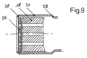
- FIG. 9 shows another alternative embodiment of the present Invention, particularly with regard to additional Firmness and preventing slipping is advantageous.
- the partial sectional view of the Fig. 9 shows, comparable to the view in Fig. 3, one rear, opposite the connection area 44 End region of the connector sleeve 18, this, as in the Fig. 9 shown, with an aligned metal disc 56 additionally is provided.
- This metal disc 56 is preferred injected or injected onto the insulator region 18 (alternatively: glued) and ensures in the end area shown the connecting device for additional strength:
- the flanging 38 now namely engages on the circumference on the disc 56, so that a considerable Strength increase can be achieved.
- FIG. 9 shows a circumferential one in the right area Contact surface 58 in the form of a step-shaped cross section Forming of the metal sleeve 34. As can be seen immediately is thereby an abutment at the opposite end created, and the contact pressure can be increased further will.
- the cavity 44 not only after assembly of the Fill metal sleeve 34 with the insulating material, but rather, do this before the jacket 34 is put on is.
- the welding contacts in the area are preferred for this purpose 44 with two half-shells, before the jacket 34 is assembled.
- About a thermal treatment then swelling or volume expansion of these half-shells, which are suitably made from PU foam can, then causes the intended sealing effect is achieved with little effort without that Sealant must be injected.
- the welding contacts 20 in front of one Assembly of the jacket 34 to overmold.
- a cooling or Cold treatment of this molded contact area before a Assembly of the jacket 34 then leads to shrinkage or negative volume change, which is easy to put on of the jacket.
- the connection area 44 with the sealant returned to normal temperature or one Exposed to heat treatment, which causes swelling and so that the intended sealing effect is achieved.
- the present invention enables the present invention an extraordinarily economical production, the in a particularly favorable way for automation and suitable for large series production.
- a metal jacket to be subsequently sprayed out makes a hardening or cooling cycle in an injection molding machine unnecessary, so that possible manufacturing cycle cycles are significantly reduced are.
- the metal jacket ensures its thermal conductivity for good protection also against short-term, selective high-temperature effects that even above a melting temperature of the filler can lie.
- connection is available between the wires and training of the contacts, such as welding or Soldering methods of any kind, especially round sleeves instead of the semicircular shells described, or even the Manufacture of plug contacts.
- Connection device in particular also possible to provide a suitable pressed or turned part.
Abstract
Description
- Fig. 1:
- eine Seitenansicht der mittels der erfindungsgemäßen Verbindungsvorrichtung bzw. des erfindungsgemäßen Verfahrens zu verbindenden, gerätespezifischen Zuleitung;
- Fig. 2:
- eine Seitenansicht der mit der Zuleitung gemäß Fig. 1 als Kupplungspartner zu verbindenden Fühlerzuleitung;
- Fig. 3:
- eine vergrößerte Schnittdarstellung der Verbindungsanordnung gemäß einer ersten, bevorzugten Ausführungsform im montierten Zustand;
- Fig. 4:
- eine Seitenansicht der Anordnung gemäß Fig. 3;
- Fig. 5:
- eine vergrößerte Schnittansicht des Verbindungsbereichs gemäß einer zweiten, alternativen Ausführungsform ohne Dichtstück;
- Fig. 6:
- eine Seitenansicht der Anordnung gemäß Fig. 5;
- Fig. 7:
- eine schematische Schnittansicht einer Weiterbildung der vorliegenden Erfindung zum weiteren Verbessern der Dichtwirkung;
- Fig. 8:
- eine Seitenansicht einer Verbindungsanordnung gemäß Fig. 7 und
- Fig. 9:
- eine ausschnittsweise Schnittansicht der erfindungsgemäßen Verbindungsvorrichtung gemäß einer weiteren, bevorzugten Ausführungsform, betreffend in vergrößerter Detailansicht den steckerseitigen Bereich.
Claims (17)
- Verbindungsvorrichtung zum feuchtigkeitsgeschützten, elektrischen Verbinden zweier mehradriger Leitungsenden, miteiner Mehrzahl von ersten, aus einem Steckerstück (18) herausgeführten Kontaktelementen (20) einer ersten Leitung (14),einer Mehrzahl von aus einem starren Leitungsmantel (30) herausgeführten Drahtenden (22) einer zweiten Leitung (24),die zum unlösbaren elektrischen Verbinden mit den Kontaktelementen (20) mit diesen fluchtend ausgerichtet sind, undeinem einen Verbindungsbereich zwischen den Drahtenden (22) und den Kontaktelementen (20) umschließenden Hülsenelement (34) aus metallischem Material, das einends dichtend und unlösbar mit dem starren Leitungsmantel (30) verbunden ist und sich anderenends über das Steckerstück (18) erstreckt, wobei ein von dem Hülsenelement (34) umschlossener Hohlraum (44) zumindest im Verbindungsbereich mit einer aushärtbaren, wärmebeständigen und elektrisch isolierenden Dichtmasse ausgefüllt ist oder dort eine durch Wärmeeinfluß volumenveränderliche und elektrisch isolierende Dichtmasse aufweist.
- Vorrichtung nach Anspruch 1, dadurch gekennzeichnet, daß die Verbindung zwischen dem starren Leitungsmantel (30) und dem Hülsenelement (34) durch eine mechanische Verformung der Verbindungspartner, insbesondere einem Crimpvorgang, hergestellt ist.
- Vorrichtung nach Anspruch 1 oder 2, dadurch gekennzeichnet, daß das Steckerstück (18) blockartig und i.w. zylindrisch aus unelastischem Kunststoffmaterial realisiert ist und das Hülsenelement (34) sich über das zylindrische Steckerstück (18) erstreckt und endseitig eine umlaufende Bördelung (38) zur Begrenzung einer Relativbewegung zwischen dem Steckerstück (18) und dem Hülsenelement (34) aufweist.
- Vorrichtung nach einem der Ansprüche 1 bis 3, dadurch gekennzeichnet, daß das Hülsenelement (34) im Bereich des Hohlraums (44) einen in seinem Mantel vorgesehenen Durchbruch aufweist, der zum Einspritzen oder Eingießen der Dichtmasse in den Hohlraum (44) ausgebildet ist.
- Vorrichtung nach einem der Ansprüche 1 bis 4, dadurch gekennzeichnet, daß die Dichtmasse als unter Wärmeeinwärmung aushärtendes Harz oder als Silikonfüllmasse realisiert ist.
- Vorrichtung nach einem der Ansprüche 1 bis 5, dadurch gekennzeichnet, daß das Hülsenelement (34) im verbindungsseitigen Endbereich der zweiten Leitung (24) zum Ausbilden eines durchmesserreduzierten Abschnittes (48) in Kontakt mit dem Leitungsmantel (30) der zweiten Leitung (30) verformt ist.
- Vorrichtung nach Anspruch 6, dadurch gekennzeichnet, daß ein zwischen dem durchmesserreduzierten Abschnitt (48) und dem starren Leitungsmantel (30) gebildeter Spalt (46) mit einem Dichtmittel gefüllt ist.
- Vorrichtung nach Anspruch 7, dadurch gekennzeichnet, daß das Dichtmittel der in den Hohlraum einzufüllenden oder eingefüllten Dichtmasse entspricht.
- Vorrichtung nach einem der Ansprüche 1 bis 8, dadurch gekennzeichnet, daß im Endbereich der zweiten Leitung (24) ein i.w. zylindrisches Dichtstück (40) den starren Leitungsmantel (30) umschließend aufgesetzt ist, das Hülsenelement (34) das Dichtstück (40) mantelseitig umschließt und eine verbindungsseitige Wand des Dichtstücks (40) den Hohlraum (44) begrenzt.
- Vorrichtung nach Anspruch 9, dadurch gekennzeichnet, daß die verbindungsseitige Wand des Dichtstücks (40) Führungsnuten für die Drahtenden (22) aufweist.
- Vorrichtung nach einem der Ansprüche 1 bis 10, dadurch gekennzeichnet, daß das Hülsenelement (34) im Endbereich der zweiten Leitung und/oder im Bereich des Steckerstücks (18) mit einer umlaufenden, eine Dichtwirkung herbeiführenden Vertiefung (54) versehen ist.
- Verfahren zum Herstellen einer feuchtigkeitsgeschützten, elektrischen Verbindung zweier mehradriger Leitungsenden, mit den Schritten:Ausrichten einer Mehrzahl von ersten, aus einem Steckerstück (18) herausgeführten Kontaktelementen (20) einer ersten Leitung (10) mit einer entsprechenden Mehrzahl von aus einer zweiten Leitung (24) herausgeführten Drahtenden (22),unlösbares, elektrisches Verbinden eines jeweiligen der Kontaktelemente (20) mit einem zugehörigen der Drahtenden (22),Aufschieben eines metallischen Hülsenelements (34) über den Verbindungsbereich zwischen den Kontaktelementen (20) und den Drahtenden (22),mechanisches, unlösbares Verbinden des metallischen Hülsenelements (34) mit einem starren Mantel (30) der zweiten Leitung (24) in einem zugehörigen Endbereich des Hülsenelements (34) undAusfüllen eines durch das Steckerstück (18) und die mechanische, unlösbare Verbindung beidseitig begrenzten, von dem Hülsenelement (34) umschlossenen Hohlraums (44) mit einer wärmebeständigen, elektrisch isolierenden Dichtmasse durch eine Öffnung im Hülsenelement (34).
- Verfahren nach Anspruch 12, gekennzeichnet durch den Schritt:Herstellen einer Bördelung (38) im steckerstückseitigen Endbereich des Hülsenelements (34).
- Verfahren nach Anspruch 12 oder 13, gekennzeichnet durch den Schritt:Herstellen einer umlaufenden, rinnenförmigen Vertiefung (54) im Endbereich der zweiten Leitung (44) und/oder im Bereich des Steckerstücks (18).
- Verfahren nach einem der Ansprüche 12 bis 14, gekennzeichnet durch den Schritt:Aufsetzen eines i.w. zylindrischen Dichtstückes (40) auf den Endbereich der zweiten Leitung, wobei das Hülsenelement (34) sich über das Dichtstück (40) erstreckt.
- Verwendung der Verbindungsvorrichtung nach einem der Ansprüche 1 bis 11 zur Verbindung eines Abgasfühlerelements für eine Heizungsanlage mit einer mit der ersten Leitung (10) zu verbindenden, elektronischen Steuereinrichtung.
- Verwendung der Verbindungsvorrichtung nach einem der Ansprüche 1 bis 11, zum Verbinden eines endseits an der zweiten Leitung (24) vorgesehenen Abgasfühlerelements für eine KFZ-Abgasanlage mit einer einen bauartspezifischen Stecker (12) der ersten Leitung (10) kontaktierenden KFZ-Motorelektronik.
Applications Claiming Priority (4)
| Application Number | Priority Date | Filing Date | Title |
|---|---|---|---|
| DE19706208 | 1997-02-17 | ||
| DE1997106208 DE19706208C2 (de) | 1997-02-17 | 1997-02-17 | Feuchtigkeitsgeschützte Verbindungsanordnung und Verfahren zum Herstellen einer elektrischen Verbindung |
| DE29714593U DE29714593U1 (de) | 1997-02-17 | 1997-08-15 | Vorrichtung zum Herstellen einer elektrischen Verbindung |
| DE29714593U | 1997-08-15 |
Publications (2)
| Publication Number | Publication Date |
|---|---|
| EP0859429A2 true EP0859429A2 (de) | 1998-08-19 |
| EP0859429A3 EP0859429A3 (de) | 1999-03-31 |
Family
ID=26034055
Family Applications (1)
| Application Number | Title | Priority Date | Filing Date |
|---|---|---|---|
| EP98102710A Withdrawn EP0859429A3 (de) | 1997-02-17 | 1998-02-17 | Verbindungsvorrichtung und Verfahren zum Herstellen einer elektrischen Verbindung |
Country Status (1)
| Country | Link |
|---|---|
| EP (1) | EP0859429A3 (de) |
Cited By (3)
| Publication number | Priority date | Publication date | Assignee | Title |
|---|---|---|---|---|
| EP1139538A1 (de) * | 2000-03-31 | 2001-10-04 | STN ATLAS Marine Electronics GmbH | Stromschienenkanal und Trennwanddurchführung mit Stromschienenkanal |
| DE102009011656A1 (de) * | 2009-02-04 | 2010-09-30 | Scheugenpflug Ag | Verfahren und Vorrichtung zum Verkleben |
| WO2015158327A1 (de) * | 2014-04-16 | 2015-10-22 | HARTING Electronics GmbH | Kabelabgang |
Citations (2)
| Publication number | Priority date | Publication date | Assignee | Title |
|---|---|---|---|---|
| FR2537793A1 (fr) * | 1982-12-14 | 1984-06-15 | Eurofarad | Connecteur electrique a haute resistance chimique, mecanique et thermique et son procede de fabrication |
| US4976796A (en) * | 1987-11-12 | 1990-12-11 | Mtu Motoren- Und Turbinen Union Muenchen Gmbh | Method for electrically and mechanically connecting the ends of two jacketed electrical conductors to each other |
-
1998
- 1998-02-17 EP EP98102710A patent/EP0859429A3/de not_active Withdrawn
Patent Citations (2)
| Publication number | Priority date | Publication date | Assignee | Title |
|---|---|---|---|---|
| FR2537793A1 (fr) * | 1982-12-14 | 1984-06-15 | Eurofarad | Connecteur electrique a haute resistance chimique, mecanique et thermique et son procede de fabrication |
| US4976796A (en) * | 1987-11-12 | 1990-12-11 | Mtu Motoren- Und Turbinen Union Muenchen Gmbh | Method for electrically and mechanically connecting the ends of two jacketed electrical conductors to each other |
Cited By (4)
| Publication number | Priority date | Publication date | Assignee | Title |
|---|---|---|---|---|
| EP1139538A1 (de) * | 2000-03-31 | 2001-10-04 | STN ATLAS Marine Electronics GmbH | Stromschienenkanal und Trennwanddurchführung mit Stromschienenkanal |
| DE102009011656A1 (de) * | 2009-02-04 | 2010-09-30 | Scheugenpflug Ag | Verfahren und Vorrichtung zum Verkleben |
| WO2015158327A1 (de) * | 2014-04-16 | 2015-10-22 | HARTING Electronics GmbH | Kabelabgang |
| US9774132B2 (en) | 2014-04-16 | 2017-09-26 | HARTING Electronics GmbH | Cable outlet with curable polymer |
Also Published As
| Publication number | Publication date |
|---|---|
| EP0859429A3 (de) | 1999-03-31 |
Similar Documents
| Publication | Publication Date | Title |
|---|---|---|
| DE3041657C2 (de) | ||
| DE102004060186B4 (de) | Verbindungskappe und Kabelverbindungsverfahren, welches dieselbe verwendet | |
| EP2932566B1 (de) | Autoladestecker | |
| DE102018005264B4 (de) | Draht mit Anschluss, Verbindervorrichtung und Herstellungsverfahren | |
| EP2449581B1 (de) | Verfahren zur herstellung eines elektronischen bauteils | |
| EP1920506B1 (de) | Elektrischer steckverbinder und verfahren zu dessen herstellung | |
| EP2485337B1 (de) | Kupplungsteil für Leitungen | |
| EP2245705B1 (de) | Steckverbinderelement mit abdichtung im kabelanschlussbereich | |
| EP3477777B1 (de) | Elektrische leitung mit schirmausleitung | |
| EP2950399B1 (de) | Abdichtung der Verbindungsstelle zwischen zwei Leitern | |
| EP0859429A2 (de) | Verbindungsvorrichtung und Verfahren zum Herstellen einer elektrischen Verbindung | |
| EP1239273A1 (de) | Sensor, insbesondere Temperatur-Sensor | |
| DE19706208C2 (de) | Feuchtigkeitsgeschützte Verbindungsanordnung und Verfahren zum Herstellen einer elektrischen Verbindung | |
| DE102010030958A1 (de) | Anordnung, insbesondere Stecker und Verfahren zur Herstellung | |
| DE10054501A1 (de) | Kabeleinführung | |
| DE102018006083A1 (de) | Abdichteinrichtung und Verfahren zum Abdichten zumindest einer Verbindungsstelle sowie beheizbare Medienleitung mit zumindest einer Abdichteinrichtung | |
| EP1837955A1 (de) | Halteschutzbuchse für einen Steckverbinder | |
| DE102007034817B4 (de) | Gedichtetes Kontaktgehäuse für eine elektrische Steckverbindung in einem Fahrzeug | |
| DE202012012274U1 (de) | Temperaturmessanordnung | |
| EP3145040B1 (de) | Leitungssatz mit einer verbindungsstelle | |
| DE102021110681B3 (de) | Steckverbindung für Airbag-Zündsysteme | |
| DE4309028B4 (de) | Geber und Verfahren zur Herstellung eines Gebers | |
| DE102011116032B4 (de) | Masse-Anschluss für abgeschirmte Kabel | |
| DE4440189C2 (de) | Verfahren zur Herstellung einer elektrischen Verbindung | |
| DE102012101232B4 (de) | Glühkerzensteckverbinder |
Legal Events
| Date | Code | Title | Description |
|---|---|---|---|
| PUAI | Public reference made under article 153(3) epc to a published international application that has entered the european phase |
Free format text: ORIGINAL CODE: 0009012 |
|
| AK | Designated contracting states |
Kind code of ref document: A2 Designated state(s): AT BE CH DE DK ES FI FR GB GR IE IT LI LU MC NL PT SE |
|
| AX | Request for extension of the european patent |
Free format text: AL;LT;LV;MK;RO;SI |
|
| PUAL | Search report despatched |
Free format text: ORIGINAL CODE: 0009013 |
|
| AK | Designated contracting states |
Kind code of ref document: A3 Designated state(s): AT BE CH DE DK ES FI FR GB GR IE IT LI LU MC NL PT SE |
|
| AX | Request for extension of the european patent |
Free format text: AL;LT;LV;MK;RO;SI |
|
| AKX | Designation fees paid | ||
| STAA | Information on the status of an ep patent application or granted ep patent |
Free format text: STATUS: THE APPLICATION IS DEEMED TO BE WITHDRAWN |
|
| 18D | Application deemed to be withdrawn |
Effective date: 19991001 |
|
| REG | Reference to a national code |
Ref country code: DE Ref legal event code: 8566 |