EP0858950B1 - Hand-held labeller - Google Patents
Hand-held labeller Download PDFInfo
- Publication number
- EP0858950B1 EP0858950B1 EP19980102451 EP98102451A EP0858950B1 EP 0858950 B1 EP0858950 B1 EP 0858950B1 EP 19980102451 EP19980102451 EP 19980102451 EP 98102451 A EP98102451 A EP 98102451A EP 0858950 B1 EP0858950 B1 EP 0858950B1
- Authority
- EP
- European Patent Office
- Prior art keywords
- tape
- label
- selecting
- plate
- stamper
- Prior art date
- Legal status (The legal status is an assumption and is not a legal conclusion. Google has not performed a legal analysis and makes no representation as to the accuracy of the status listed.)
- Expired - Lifetime
Links
- 238000004519 manufacturing process Methods 0.000 description 5
- 238000000034 method Methods 0.000 description 4
- 230000008878 coupling Effects 0.000 description 3
- 238000010168 coupling process Methods 0.000 description 3
- 238000005859 coupling reaction Methods 0.000 description 3
- 208000037265 diseases, disorders, signs and symptoms Diseases 0.000 description 2
- 238000003825 pressing Methods 0.000 description 2
- 208000024780 Urticaria Diseases 0.000 description 1
- 238000007796 conventional method Methods 0.000 description 1
- 238000003780 insertion Methods 0.000 description 1
- 230000037431 insertion Effects 0.000 description 1
Images




Classifications
-
- B—PERFORMING OPERATIONS; TRANSPORTING
- B65—CONVEYING; PACKING; STORING; HANDLING THIN OR FILAMENTARY MATERIAL
- B65C—LABELLING OR TAGGING MACHINES, APPARATUS, OR PROCESSES
- B65C11/00—Manually-controlled or manually-operable label dispensers, e.g. modified for the application of labels to articles
- B65C11/02—Manually-controlled or manually-operable label dispensers, e.g. modified for the application of labels to articles having printing equipment
- B65C11/0205—Manually-controlled or manually-operable label dispensers, e.g. modified for the application of labels to articles having printing equipment modified for the application of labels to articles
- B65C11/021—Manually-controlled or manually-operable label dispensers, e.g. modified for the application of labels to articles having printing equipment modified for the application of labels to articles label feeding from strips
- B65C11/0215—Labels being adhered to a web
- B65C11/0236—Advancing the web by a cog wheel
- B65C11/0247—Advancing the web by a cog wheel by actuating a handle manually
-
- B—PERFORMING OPERATIONS; TRANSPORTING
- B65—CONVEYING; PACKING; STORING; HANDLING THIN OR FILAMENTARY MATERIAL
- B65C—LABELLING OR TAGGING MACHINES, APPARATUS, OR PROCESSES
- B65C2210/00—Details of manually controlled or manually operable label dispensers
- B65C2210/0037—Printing equipment
- B65C2210/004—Printing equipment using printing heads
- B65C2210/0045—Printing equipment using printing heads mechanically actuated, e.g. by a hand lever
- B65C2210/0048—Means for controlling the force of the printing head
-
- B—PERFORMING OPERATIONS; TRANSPORTING
- B65—CONVEYING; PACKING; STORING; HANDLING THIN OR FILAMENTARY MATERIAL
- B65C—LABELLING OR TAGGING MACHINES, APPARATUS, OR PROCESSES
- B65C2210/00—Details of manually controlled or manually operable label dispensers
- B65C2210/0072—Specific details of different parts
- B65C2210/0075—Applying rollers
-
- B—PERFORMING OPERATIONS; TRANSPORTING
- B65—CONVEYING; PACKING; STORING; HANDLING THIN OR FILAMENTARY MATERIAL
- B65C—LABELLING OR TAGGING MACHINES, APPARATUS, OR PROCESSES
- B65C2210/00—Details of manually controlled or manually operable label dispensers
- B65C2210/0072—Specific details of different parts
- B65C2210/0086—Specific details of different parts platens
Definitions
- the present invention relates to an improved label stamper which is capable of stamping prices on labels attached on a tape so as to attach the stamped labels on commodities.
- the label stamper is a machine which stamps prices on labels to attach them on commodities.
- the label stamper has a complicated structure.
- the label stamper includes: (1) a means for loading a label tape into a case; (2) a guide means for guiding the loaded label tape toward a stamper; (3) a holding means for firmly holding the guided label tape onto the stamper; (4) a stamping means for stamping prices on labels; and (5) a carrying means for attaching the stamped labels on commodities, and for pulling the empty tape to discharge it to the outside.
- These means have various structures respectively, and the constitution of the structures of the different means decide the superiority of the label stamper.
- the tape carrying roller is secured to the machine by means of supporting shafts, and therefore, the assembling procedure is very complicated. Further, they cannot maintain balance with the other assembling procedure of the other components, and therefore, the production line stopped frequently, with the result that the production cost is increased. Further, even if the carrying roller is damaged during the use, its replacement is almost impossible, with the result that the whole stamping machine becomes useless.
- the present invention is intended to overcome the above described disadvantages of the conventional techniques.
- the tape loading means of the label stamper according to the present invention is constituted such that a loading case goes in and out of the machine by functions of a pair of folding and extending legs, so that the label tape can be loaded in a convenient manner.
- the guide means for the label tape according to the present invention is constituted such that a front plate and a rear plate are fastened across a narrow gap, and in this gap, a guide channel is formed. A side of this channel is open, and the tape is inserted into the open portion of the channel in a convenient and speedy manner.
- the holding means of the label stamper according to the present invention is constituted such that a push plate is disposed facing toward a base plate, and the push plate interlocks a movable lever to the loading case.
- the stamping means of the label stamper according to the present invention is constituted as follows. That is, a selecting hole of a selecting wheel for driving a stamping belt is provided with a recess and a triangular protuberance. Thus two selecting wheals will never be engaged simultaneously, and fingers of a selecting bar are accurately coupled to the selected wheel. Therefore, the desired characters can be accurately and conveniently selected.
- the stamping means includes an ink roller of a known type and an interlocking mechanism for the ink roller.
- the carrying rollers for the tape are provided in the form of a cartridge, and this cartridge is replaceably accommodated within a cartridge room. This improves the compactness and the performance of the label stamper, and the cartridge can be conveniently replaced.
- the label stamper according to the present invention shows improved functions, with the result that the label stamper is not liable to disorders, and its use is convenient.
- the label stamper according to the present invention includes:
- the above described function means 100, 200, 300, 400 and 500 have improved structures compared with the conventional means.
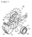
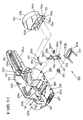
- FIG. 1-1 is a perspective view showing the tape loading means 100 of the label stamper of the present invention, with the side plate removed
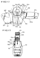
- FIG. 1-2 is a side view showing the loaded state of the tape roll.
- FIG. 1-3 is a longitudinal sectional view of it.
- a tape loading room 102 is formed at a middle of a main body 101.
- the tape loading room 102 is surrounded by side plates 102a, and its top is open.
- On one of the side plates 102a of the tape loading room 102 there are disposed a pair of joint type legs 104 supported by shafts 105 and 105'.
- a loading case 103 is disposed above the legs 104.
- a torsion spring 105s is installed on each of the legs 104, so that the legs 104 can be extended.
- a shaft 103b projects at the middle of the side plate 103a. Another side of the loading case 103 is open. The outer end of the shaft 103b forms a free end 103b'.
- a plurality of labels 106 are attached aligned in one straight line on a tape 106, this being a known type.
- a shaft hole 106b of a tape roll 106r on which the tape 106 is wound is fitted to the shaft 103b from the free end 103b', thereby loading the tape roll into the loading case 103.
- An arcuate cover 103c is disposed above the loading case 103, and the cover 103c is provided with an engaging step 103d.
- the loading room 102 is provided with a locking lever 103e having an engaging step 103d', so that it can be coupled to the engaging step 103d of the cover 103c.
- the engaging step 103d of the cover 103c is coupled to the engaging step 103d' of the locking lever 103e so as to be locked.
- the cover 103c which is disposed above the loading case 103 arcuately covers the loading room 102, thereby protecting the tape.
- the lower half portion of the loading case 103 is inserted into the loading room 102, while the upper half portion of the loading case 103 is exposed above the main body. Therefore, the remaining amount of the tape can be confirmed visually.
- a part of the tape roll 106b is exposed to the outside of the loading room 102, the tape roll does not depart from the loading room.
- Each of the legs 104 of the loading case 103 consists of an upper leg 104a and a lower leg 104b, these two being connected by a shaft 104d of a joint 104c. That is, the upper and lower legs are connected by a hinge, so that the legs 104 can be folded and extended.
- the upper and lower portions of the upper and lower legs 104a and 104b are provided with teeth 104g and 104g' like gears, and these teeth are meshed together. Owing to the mesh of the teeth, the upper and lower legs 104a and 104b of the two legs 104 actuate at the same angle, so that the loading case can move vertically up and down.
- a torsion spring 105s is installed on each of the shafts 105' of the legs 104, thereby providing elastic forces to the legs 104.
- the locking lever 103e is pulled to a side to release the two engaged engaging steps 103d and 103d', then the folded legs 104 extend upward as shown in Table 1-3. Under this condition, owing to the extension of the legs 104, the loading case 103 which has been accommodated within the loading room 102 protrudes upward. When the loading case is thus protruded, the tape roll 106r can be loaded in a convenient manner.
- This loading device is improved compared with the conventional ones, while its aesthetic appearance is nice, as well as being convenient to use.
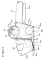
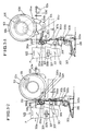
- FIG. 2-1 is a perspective view showing the guide channel means 200 for the label tape of the present invention.
- FIG. 2-2 is a perspective view showing the guide means in detail, with the side plate removed.
- FIG. 2-3 is a side view showing the label tape inserted into the guide channel of the label stamper according to the present invention.
- a side plate 202 of the main body 101 is divided into a front side plate 202a and a rear side plate 202b. These two side plates 202a and 202b are attached onto a side of the main body 101 through screws 205 and screw holes 205a and 205b, leaving a small gap between them. This gap is a guide channel 203 through which the tape runs.
- a guide plate 202c is formed on the front end of the rear plate 202b, and this guide plate 202c forms a side wall of the guide channel 203.
- the guide channel 203 is bent in an L shape. However, it will not be limited to the drawn shape, but can be modified to any other shape.
- the contours of the front and rear plates 202a and 202b are varied. Further, the guide channel 203 is decided by the front and rear plates 202a and 202b. This channel 203 is open, and this feature is that which is different from the conventional ones.
- the tape 106 which is accommodated within the loading room 102 can be inserted into the guide channel 203 through the open portion. This is an improved feature compared with the conventional ones in which the tape is inserted into a guide hole.
- the guide channel 203 guides the label tape 106 into under a stamp P, so that the labels can be stamped.
- a base plate 206 which is formed on the rear side plate 202b (refer to FIG. 3-1).
- the base plate 206 is a pad for supporting the stamping. Facing to a sharp edge of the base plate 206, there is an attaching roller 207 which is rotatably secured on the lower end of the front side plate 202a.
- the stamped labels 106a are detached from the tape 106 at the sharp edge of the base plate 206 due to the bent running of the tape. Then the detached labels are attached onto the commodities owing to the pressing of the attaching roller 207. That is, if the handle 204 is grasped, and if the attaching roller 207 is rubbed onto the commodity, then the label is attached onto the commodity.
- FIG. 3-1 is an exploded perspective view showing the holding means 300 for the label tape of the present invention.
- FIG. 3-2 is a side view showing the critical portion of the holding means.
- FIG. 3-3 illustrates the operating state of the label tape.
- the tape holding means 300 is a device which lightly presses the label tape when stamping it, so that the label tape would not be oscillated.
- the base plate 206 faces the stamping device P in an inclined posture.
- a push plate 303 which is installed movably up and down by means of a retaining portion 303a and supporting shaft 305. Owing to the force of the coil spring 304, the push plate 303 presses the base plate 206, so that the tape 106 would be secured on the base plate 206.
- an interlocking lever 306 which is coupled to a shaft 305a by means of a shaft hole 306c together with a coil spring 304a.
- An actuation lever 307 which is installed on the main body 101 contacts with a recessed cam portion 306a of the lever 306.
- a roller 301 which is installed on a shaft 302 of the lever 306 presses or releases the label tape 106 which has been inserted into the guide channel 203. Therefore, when the tape runs, an excessive loosening of the tape is prevented.
- connection bar 310 is connected to a connection groove 104e and a connection groove 306d by means of shafts 310a and 310b.
- connection bar 310 pushes the upper portion of the interlocking lever 306 to the left, and therefore, the lower portion 306b of the lever 306 departs from the lever 303b of the push plate 303.
- the push plate 303 closely contacts to the base plate 206 to lightly press down the tape on the base plate 206. This prevents the movements of the label tape during the stamping, so that the stamping can be made on the accurate positions.
- the connection bar 310 is pulled to the right by the legs 104. Therefore, the lower portion 306b of the lever 306 moves to the left, and therefore, the lower portion 306b of the lever 306 presses down the lever 303b of the push plate 303, with the result that the push plate 303 departs from the base plate 206. Under this condition, the tape 106 can be easily inserted into between the push plate 303 and the base plate 206 during a replacement of the tape.
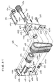
- FIG. 4-1 is an exploded perspective view showing the critical portion of the stamping means 400 according to the present invention.
- FIG. 4-2 is an enlarged side view of the stamping means.
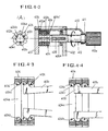
- FIG. 4-3 is an enlarged sectional view showing the shifting of the selecting bar in the selecting wheel according to the present invention.
- FIG. 4-4 is an enlarged sectional view showing a selection-contact state of the selecting bar together with the selecting wheel.
- the stamping means of the label stamper according to the present invention is capable of selecting and arranging the character blocks accurately and speedily.
- the stamper P is generally installed on the front portion of the actuation lever 307 which is actuated by a hand lever 204a.
- two side plates 401 and 402 are assembled by means of fastening screws 409 and 409' and fastening holes 409a, 409a', 402e and 402e' of a supporting plate 408a.
- a guide plate 402a with a guide groove 402b formed thereon is formed on an end of the side plate 402.
- a coupling hole 402d which is formed on an end of the guide plate 402a is coupled to a coupling protuberance 408b of the side plate 401.
- a rectangular slider 410 is inserted into the guide groove 402b of the guide plate 402a, in such a manner that the slider 410 can slide through elongate guide holes 401a and 401b formed laterally on the upper portions of the side plates 401 and 402.
- a selecting wheel 404 having a plurality of selecting steps is fitted to the guide rod 406, and at the same time, is supported by the gently curved retaining plate 408.
- a stamping wheel 405 is installed between the two side plates 401 and 402 by means of a shaft 405a and shaft holes 405b.
- An elastic grasping ring 411 which is formed on the slider 410 receives a selecting bar 412 together with a sleeve 407 through a cut portion 411a.
- a handle 412a is formed on the rear portion of the selecting bar 412.
- a plurality of fingers 412b (3 in the drawing) having protuberances 412c are formed on the front portion of the selecting bar 412.
- the selecting bar 412 is inserted into the selecting hole 404a of the selecting wheel 404.
- an indicating pin 410a of the slider 410 is set to the desired numeral of the numeral part of the stamping belt 403 by shifting the selecting bar 412 by holding the handle 412a.
- the selecting hole 404a is provided with a plurality of ridges 404b and furrows 404c. As shown in FIG. 4-2a, the protuberances 412c of the fingers 412a of-the selecting bar 412 are inserted into the furrows 404c of the selecting hole 404a so as to be clutched owing to the elasticity of the fingers.
- the selecting wheel is rotated by turning the selecting bar 412 by grasping the handle 412a, the clutched selecting wheel is rotated, and the stamping belt 403 is also rotated. Thus the selected numeral is placed on the lower stamping wheel 405.
- a triangular protuberance 404c' is formed on each of the furrows 404c of the selecting hole 404a of the selecting wheel 404.
- the fingers 412b are easily shifted in a state inserted into the furrows 404c.
- the protuberances 412c of the fingers 412b are halted by the triangular protuberances 404c' so as to be engaged into the selecting hole 404a of the selecting wheel 404. Therefore, they cannot be coupled to an intermediate position. Accordingly, the character blocks can be accurately selected.
- the guide rod 406 is inserted into the guide hole 406a of the selecting bar 412, and therefore, it moves straightly during the shifting manipulation.
- the stamping belt 403 is coupled to the selecting wheel 404 and the stamping wheel 405, and therefore, the characters (letters and numerals) can be arbitrarily selected to stamp prices.
- FIG. 5-1 is an exploded perspective view showing the tape carrying means 500 of the label stamper according to the present invention.
- FIG. 5-2 is an exploded perspective view of the tape carrying cartridge according to the present invention.
- FIG. 5-3 is a perspective view of the tape carrying cartridge.
- FIG. 5-4 is a longitudinal sectional view of the tape carrying cartridge.
- FIG. 5-5 is a side sectional view taken along a line A-A of FIG. 5-4.
- FIG. 5-6 is a side sectional view taken along a line B-B of FIG. 5-4.
- FIG. 5-7 illustrates the assembled state of the tape carrying cartridge according to the present invention.
- the label tape carrying means 500 includes an actuation mechanism A and a carrying cartridge B.
- the actuation mechanism A includes a hand lever 204a movably secured to the main body 101 by means of a supporting shaft 501.
- An actuation lever 307 extends from a hand lever 204a.
- An actuation piece 502 extends vertically downward from the middle of the actuation lever 307.
- the actuation piece 502 is provided with a connection groove 502a which is connected to a crank shaft 505b of the cartridge.
- the principal feature of the present invention in this respect is that the carrying roller is provided in the form of the cartridge.
- the tape carrying cartridge B is constituted as follows. That is, between two side plates 503a and 503b of a cartridge case 503, there are installed a carrying roller 504 having a plurality of teeth 504a and a ratchet wheel 505 by means a. supporting shaft 506 and shaft holes 505a'. In a recess 504b of the carrying roller 504, there are formed a plurality of shaft holes 504' in which ratchet poles 504c are inserted, the ratchet poles 504c forming a circular contour.
- Free ends 504c' of the ratchet poles 504c are contacted to a ratchet gear 505a of the ratchet wheel 505.
- a crank shaft 505b of the ratchet wheel 505 is inserted into an elongate arcuate slot 503c of the side plate 503a of the cartridge to be exposed to the outside.
- this crank shaft 505b is connected to a connection piece 502 of the actuation piece 502 shown in FIG. 5-1.
- the ratchet wheel 505 is rotated clockwise or anticlockwise owing to the actuation of the crank shaft 505b.
- the carrying roller 504 is interlocked to one direction rotation of the ratchet wheel 505.
- a guide roller 508 is installed by means of a supporting shaft 506a and a shaft hole 508a.
- the both ends of the supporting shaft 506a are coupled to fastening holes 506a' of the side plates 503e and 503b by means of fastening screws 510a.
- the guide roller 508 plays the role of guiding the label tape 106 to the carrying roller 504.
- the carrying roller 504 there are installed tape push plates 507 by means of coupling portions 507a and 507b and the supporting shafts 506a and 506b.
- the tape 106 which is guided by the guide roller 508 and the tape push plates 507 is engaged with the teeth 504a of the carrying roller 504. Therefore, in accordance with the rotation of the carrying roller, the tape 106 is pulled to be carried.
- the stamped labels are carried to the attaching roller 207 to be attached onto commodities.
- a directing plate 509 on the side plates 503a and 503b of the cartridge by means of the supporting shaft 506c and the shaft hole 509a, for directing the tape 106 to the outside.
- the supporting shaft 506c is inserted into a hole 506c' of the side plate 503b, and is fastened by means of screws (not shown in the drawing).
- Supporting rods 506d are inserted into holes 506d' of the side plate 503b, and are fastened by means of screws (not shown in the drawing).
- the carrying roller is provided in the form of a cartridge, and the cartridge B is inserted into the cartridge loading room R of the main body 101 so as to be fastened by means of screws (not shown in the drawing) and fastening holes 510 as shown in FIG. 5-7.
- the cartridge B can be replaced by loosening the screws.
- the label stamper can be operated as follows. That is, if the handle 204 and the hand lever 204a are held by hand, and if the two are pressed together like when manipulating a scissor, then the actuation lever 307 moves downward. As a result, ink is spread on the relevant character block of the stamping belt 403 by the ink roller Ro, and the price is stemped on the label 106a which is held between the push plate 303 and the base plate 206. Then if the grasped hand lever 204a is released, then the hand lever 204a is spread owing to the elastic restoring force of the torsion spring 204s. At the same time, the actuation lever 307 moves upward. Thus the stamping device P is restored to the original position. Under this condition, the actuation piece 502 moves to the left and right, so that the crank shaft 505b of the carrying cartridge would be rotated clockwise and anticlockwise.
- the ratchet wheel 505 is rotated, with the result that the carrying roller 504 revolves as much as the rotated angle of the ratchet wheel 505.
- the tape which is partly wound on the carrying roller is carried.
- the carrying distance is equal to the width of a label 106a which is attached on the tape.
- the stamped labels are attached on the tape, but owing to the sharp triangular edge of the base plate 206, the tape is bent at that point, so that the labels would be detached from the tape.
- the tape plays the role of a conveyor for the labels, and this is a known feature.
- the tape loading means 100, the tape guide means 200, the label tape holding means 300, the label stamping means 400 and the tape carrying means 500 in the label stamper according to the present invention have novel features compared with the conventional ones.
- the loading case is made to project to the outside of the main body, so that the tape can be loaded in a speedy and simple manner.
- a side of the guide channel is open, and therefore, the tape can be easily inserted into the guide channel. Further, the tape guiding distance is short.
- the tape holding means presses the tape onto the base plate in an automatic manner owing to the up and down movements of the loading case. Therefore an additional devices are not needed unlike the conventional ones. Therefore, an attention is not required to the pressing of the tape onto the base plate.
- the selecting hole of the selecting wheel of the stamping means is provided with recesses and triangular protuberances. Therefore, owing to the triangular protuberances, the fingers of the selecting bar are coupled to only one selecting wheel in an accurate manner. Therefore unlike the conventional ones, the relevant character blocks can be accurately selected and arranged.
- the tape carrying means is provided in the form of a cartridge. Therefore the manufacturing cost for the label stamper can be saved in carrying out its mass production. Further, if the carrying roller is damaged during the use, it can be replaced in a simple manner, and therefore, the label stamper can be conveniently used even in a crowded store.
Landscapes
- Labeling Devices (AREA)
Description
- The present invention relates to an improved label stamper which is capable of stamping prices on labels attached on a tape so as to attach the stamped labels on commodities.
- Generally, the label stamper is a machine which stamps prices on labels to attach them on commodities. The label stamper has a complicated structure.
- That is, the label stamper includes: (1) a means for loading a label tape into a case; (2) a guide means for guiding the loaded label tape toward a stamper; (3) a holding means for firmly holding the guided label tape onto the stamper; (4) a stamping means for stamping prices on labels; and (5) a carrying means for attaching the stamped labels on commodities, and for pulling the empty tape to discharge it to the outside. These means have various structures respectively, and the constitution of the structures of the different means decide the superiority of the label stamper.
- The prior art for the present invention will be described below.
- (1) one example of the loading means for loading the label tape of the label stamper is disclosed in Japanese Utility Model Laid-open No. Sho-59-3814 (dated Jan. 11, 1984). In this tape loading device, a tape roll is inserted into a narrow loading chamber of the label stamper. In this prior art, the tape roll is inserted into the narrow loading chamber, and a supporting shaft is fitted into a retainer. This procedure is very complicated, and inconvenient. Further, it frequently happens that the tape is not smoothly loosened.Other loading means are known, but they are also inconvenient like the above described device. However, within a crowded store, it is needed that the tape roll has to be quickly replaced.
- (2) One example of the guide means for guiding the label tape is disclosed in Korean Utility Model Publication No. 90-1370. In this guide means, a guide hole is formed vertically from the top of the stamping machine like a tunnel. The end of the label tape is inserted into the tunnel shaped guide hole from above to pass through the bottom of the machine. Then the tape is carried by a carrying roller. In this prior art, the label tape is liable to be bent or folded within the tunnel, and therefore, it is very inconvenient to insert the label tape.
- (3) Example of the holding means for holding the tape are disclosed in Korean Patent Publication No. 82-1815 (dated Oct. 12, 1982) and Korean Patent application Laid-open No. 88-12449 (Nov. 26, 1988). In these devices, a lower plate which is provided with a push plate can be opened and closed by means of a hinge.Therefore, when inserting the tape into the guide hole, the lower plate is opened, then the tape is inserted into the guide hole, and then, the lower plate is closed, so that the push plate would push up the tape.In these devices, each time when the label tape is replaced, the lower plate has to be opened and closed, this being a troublesome task. Further, their structure is very complicated, and therefore, the manufacturing cost becomes high, as well as being liable to disorders. Further, the operation procedure for the stamping machine is very complicated.
- (4) The important matter in the label stamping is the shifting of the character blocks. One example of the stamping means is disclosed in Korean Utility Model Publication No. 83-2593 (dated Dec. 7, 1983), Korean Patent Application Laid-open No. 88-308 (dated Mar. 24, 1988), and Korean Patent Publication No. 80-1096 (dated Oct. 6, 1980). Further, other examples are known. In one of these devices, the selecting wheel has to be rotated manually, and therefore, the selecting wheel is very inconvenient.In another, the selecting wheel is rotated by means of a selecting bar. When shifting the selecting bar, the selecting bar is engaged between two selecting wheels, with the result that the two selecting wheels are rotated simultaneously. Because of this, the selection of character blocks becomes inconvenient.
- (5) Examples of the carrying means for carrying the tape of the label stamper are disclosed in Japanese Patent Publication No. Sho-53-43038 (dated Nov. 16, 1978), Japanese Utility Model Laid-open No. 83-139 (dated Mar. 25, 1983), and Korean Utility Model Publication No. 90-3053 (dated Apr. 12, 1990).
-
- In these devices, the tape carrying roller is secured to the machine by means of supporting shafts, and therefore, the assembling procedure is very complicated. Further, they cannot maintain balance with the other assembling procedure of the other components, and therefore, the production line stopped frequently, with the result that the production cost is increased. Further, even if the carrying roller is damaged during the use, its replacement is almost impossible, with the result that the whole stamping machine becomes useless.
- The present invention is intended to overcome the above described disadvantages of the conventional techniques.
- Therefore it is an object of the present invention to provide a label stamper for use in a store for stamping prices on commodities, in which the functions are much progressed and improved.
- The tape loading means of the label stamper according to the present invention is constituted such that a loading case goes in and out of the machine by functions of a pair of folding and extending legs, so that the label tape can be loaded in a convenient manner.
- The guide means for the label tape according to the present invention is constituted such that a front plate and a rear plate are fastened across a narrow gap, and in this gap, a guide channel is formed. A side of this channel is open, and the tape is inserted into the open portion of the channel in a convenient and speedy manner.
- The holding means of the label stamper according to the present invention is constituted such that a push plate is disposed facing toward a base plate, and the push plate interlocks a movable lever to the loading case. Thus, if the tape is inserted into the guide channel, the tape is automatically press-held to the base plate. During the carriage of the tape, the tape is carried by being lightly pressed upon the base plate.
- The stamping means of the label stamper according to the present invention is constituted as follows. That is, a selecting hole of a selecting wheel for driving a stamping belt is provided with a recess and a triangular protuberance. Thus two selecting wheals will never be engaged simultaneously, and fingers of a selecting bar are accurately coupled to the selected wheel. Therefore, the desired characters can be accurately and conveniently selected.
- The stamping means includes an ink roller of a known type and an interlocking mechanism for the ink roller. Thus automatically, ink is spread on the character blocks, with the result that the characters are clearly stamped on the labels.
- In the carrying means for carrying the label tape, the carrying rollers for the tape are provided in the form of a cartridge, and this cartridge is replaceably accommodated within a cartridge room. This improves the compactness and the performance of the label stamper, and the cartridge can be conveniently replaced.
- Therefore, the label stamper according to the present invention shows improved functions, with the result that the label stamper is not liable to disorders, and its use is convenient.
- The above object and other advantages of the present invention will become more apparent by describing in detail the preferred embodiment of the present invention with reference to the attached drawings in which:
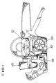
- FIG. 1 illustrates the total constitution of the label stemper of the present invention, with the side plate removed;
- FIG. 1-1 is a perspective view showing the tape loading means 100 of the label stamper of the present invention, with the side plate removed;
- FIG. 1-2 is a side view showing the loaded state of the tape roll;
- FIG. 1-3. is a frontal view showing the tape loading means partly cut off;
- FIG. 2-1 is a perspective view showing the guide channel means 200 for the label tape of the present invention;
- FIG. 2-2 is a perspective view showing the guide means in detail, with the side plate removed;
- FIG. 2-3 is a side view showing the label tape inserted into the guide channel of the label stamper according to the present invention;
- FIG. 3-1 is an exploded perspective view showing the holding means 300 for holding the label tape of the present invention;
- FIG. 3-2 is a side view showing the critical portion of the holding means;
- FIG. 3-3 illustrates the operating state of the label tape;
- FIG. 4-1 is an exploded perspective view showing the critical portion of the stamping means 400 according to the present invention;
- FIG. 4-2 is an enlarged side view of the stamping means;
- FIG. 4-2a is a frontal view of the selecting wheel;
- FIG. 4-3 is an enlarged sectional view showing the shifting of the selecting bar in the selecting wheel according to the present invention;
- FIG. 4-4 is an enlarged sectional view showing a selection-contact state of the selecting bar together with the selecting wheel;
- FIG. 5-1 is an exploded perspective view showing the tape carrying means 500 of the label stamper according to the present invention;
- FIG. 5-2 is an exploded perspective view of the tape carrying cartridge according to the present invention;
- FIG. 5-3 is a perspective view of the tape carrying cartridge;
- FIG. 5-4 is a longitudinal sectional view of the tape carrying cartridge;
- FIG. 5-5 is a side sectional view taken along a line A-A of FIG. 5-4;
- FIG. 5-6 is a side sectional view taken along a line B-B of FIG. 5-4; and
- FIG. 5-7 illustrates the assembled state of the tape carrying cartridge according to the present invention.
-
- As shown in FIG. 1, the label stamper according to the present invention includes:
- a label tape loading means 100 for loading a label tape in a convenient manner;
- a label guide means 200 with its side portion open;
- a tape holding means 300 for automatically press-holding the label tape after its insertion into a guide channel;
- a character selecting means 400 for selecting characters in an accurate and easy manner; and
- a cartridge type tape carrying means 500 for attaching stamped labels onto commodities, and for pulling out the empty tape to the outside of the label stamper.
-
- The above described function means 100, 200, 300, 400 and 500 have improved structures compared with the conventional means.
- Now the function means will be described as to their constitutions and actuations.
- FIG. 1-1 is a perspective view showing the tape loading means 100 of the label stamper of the present invention, with the side plate removed, FIG. 1-2 is a side view showing the loaded state of the tape roll. FIG. 1-3 is a longitudinal sectional view of it.
- As shown in FIG. 1-1, a
tape loading room 102 is formed at a middle of amain body 101. Thetape loading room 102 is surrounded byside plates 102a, and its top is open. On one of theside plates 102a of thetape loading room 102, there are disposed a pair ofjoint type legs 104 supported byshafts 105 and 105'. Aloading case 103 is disposed above thelegs 104. Atorsion spring 105s is installed on each of thelegs 104, so that thelegs 104 can be extended. - In the
loading case 103, ashaft 103b projects at the middle of theside plate 103a. Another side of theloading case 103 is open. The outer end of theshaft 103b forms afree end 103b'. A plurality oflabels 106 are attached aligned in one straight line on atape 106, this being a known type. Ashaft hole 106b of atape roll 106r on which thetape 106 is wound is fitted to theshaft 103b from thefree end 103b', thereby loading the tape roll into theloading case 103. - An
arcuate cover 103c is disposed above theloading case 103, and thecover 103c is provided with an engagingstep 103d. Theloading room 102 is provided with a lockinglever 103e having an engagingstep 103d', so that it can be coupled to the engagingstep 103d of thecover 103c. - As shown in FIG. 1-2, if the
case 103 is pressed down into theloading room 102, then the engagingstep 103d of thecover 103c is coupled to the engagingstep 103d' of the lockinglever 103e so as to be locked. - Since the
engaging steps lever 103e, the lockinglever 103e is not released unless it is manually released. - The
cover 103c which is disposed above theloading case 103 arcuately covers theloading room 102, thereby protecting the tape. The lower half portion of theloading case 103 is inserted into theloading room 102, while the upper half portion of theloading case 103 is exposed above the main body. Therefore, the remaining amount of the tape can be confirmed visually. Although a part of thetape roll 106b is exposed to the outside of theloading room 102, the tape roll does not depart from the loading room. - Each of the
legs 104 of theloading case 103 consists of anupper leg 104a and alower leg 104b, these two being connected by ashaft 104d of a joint 104c. That is, the upper and lower legs are connected by a hinge, so that thelegs 104 can be folded and extended. - The upper and lower portions of the upper and
lower legs teeth lower legs legs 104 actuate at the same angle, so that the loading case can move vertically up and down. Atorsion spring 105s is installed on each of the shafts 105' of thelegs 104, thereby providing elastic forces to thelegs 104. - Therefore, if the locking
lever 103e is pulled to a side to release the two engagedengaging steps legs 104 extend upward as shown in Table 1-3. Under this condition, owing to the extension of thelegs 104, theloading case 103 which has been accommodated within theloading room 102 protrudes upward. When the loading case is thus protruded, thetape roll 106r can be loaded in a convenient manner. - This loading device is improved compared with the conventional ones, while its aesthetic appearance is nice, as well as being convenient to use.
- FIG. 2-1 is a perspective view showing the guide channel means 200 for the label tape of the present invention. FIG. 2-2 is a perspective view showing the guide means in detail, with the side plate removed. FIG. 2-3 is a side view showing the label tape inserted into the guide channel of the label stamper according to the present invention.
- As shown in FIG. 2-1, a
side plate 202 of themain body 101 is divided into afront side plate 202a and arear side plate 202b. These twoside plates main body 101 throughscrews 205 and screwholes guide channel 203 through which the tape runs. - As shown in FIG. 2-2, a
guide plate 202c is formed on the front end of therear plate 202b, and thisguide plate 202c forms a side wall of theguide channel 203. In the drawing, theguide channel 203 is bent in an L shape. However, it will not be limited to the drawn shape, but can be modified to any other shape. - In accordance with the shape of the
guide channel 203, the contours of the front andrear plates guide channel 203 is decided by the front andrear plates channel 203 is open, and this feature is that which is different from the conventional ones. - Therefore, as shown in FIG. 2-3, the
tape 106 which is accommodated within theloading room 102 can be inserted into theguide channel 203 through the open portion. This is an improved feature compared with the conventional ones in which the tape is inserted into a guide hole. - The
guide channel 203 guides thelabel tape 106 into under a stamp P, so that the labels can be stamped. - On the lower portion of the
guide channel 203, there is formed abase plate 206 which is formed on therear side plate 202b (refer to FIG. 3-1). - The
base plate 206 is a pad for supporting the stamping. Facing to a sharp edge of thebase plate 206, there is an attachingroller 207 which is rotatably secured on the lower end of thefront side plate 202a. - Accordingly, if the tape is pulled by the tape carrying means (which is to be described later), the stamped
labels 106a are detached from thetape 106 at the sharp edge of thebase plate 206 due to the bent running of the tape. Then the detached labels are attached onto the commodities owing to the pressing of the attachingroller 207. That is, if thehandle 204 is grasped, and if the attachingroller 207 is rubbed onto the commodity, then the label is attached onto the commodity. - FIG. 3-1 is an exploded perspective view showing the holding means 300 for the label tape of the present invention. FIG. 3-2 is a side view showing the critical portion of the holding means. FIG. 3-3 illustrates the operating state of the label tape.
- The tape holding means 300 is a device which lightly presses the label tape when stamping it, so that the label tape would not be oscillated.
- As shown in FIG. 3-1, the
base plate 206 faces the stamping device P in an inclined posture. Above thebase plate 206, there is apush plate 303 which is installed movably up and down by means of a retainingportion 303a and supportingshaft 305. Owing to the force of thecoil spring 304, thepush plate 303 presses thebase plate 206, so that thetape 106 would be secured on thebase plate 206. - About the middle of the
side plate 102a of themain body 101, there is installed an interlockinglever 306 which is coupled to ashaft 305a by means of ashaft hole 306c together with acoil spring 304a. Anactuation lever 307 which is installed on themain body 101 contacts with a recessedcam portion 306a of thelever 306. When theactuation lever 307 is actuated up and down by means of amanual lever 204a, the interlockinglever 306 moves up and down owing to the sliding of aprotuberance 307a. - As shown in FIG. 3-2, A
roller 301 which is installed on ashaft 302 of thelever 306 presses or releases thelabel tape 106 which has been inserted into theguide channel 203. Therefore, when the tape runs, an excessive loosening of the tape is prevented. - As shown in FIG. 3-3, a
connection bar 310 is connected to aconnection groove 104e and aconnection groove 306d by means ofshafts - Therefore, when the
loading case 103 is inserted into theloading room 102 like in the FIG. 3-2, theconnection bar 310 pushes the upper portion of the interlockinglever 306 to the left, and therefore, thelower portion 306b of thelever 306 departs from thelever 303b of thepush plate 303. - Therefore, owing to the elastic force of the
coil spring 304, thepush plate 303 closely contacts to thebase plate 206 to lightly press down the tape on thebase plate 206. This prevents the movements of the label tape during the stamping, so that the stamping can be made on the accurate positions. - Meanwhile, when the
loading case 103 is protruded to the outside of theloading room 102 like in FIG. 3-3, theconnection bar 310 is pulled to the right by thelegs 104. Therefore, thelower portion 306b of thelever 306 moves to the left, and therefore, thelower portion 306b of thelever 306 presses down thelever 303b of thepush plate 303, with the result that thepush plate 303 departs from thebase plate 206. Under this condition, thetape 106 can be easily inserted into between thepush plate 303 and thebase plate 206 during a replacement of the tape. - FIG. 4-1 is an exploded perspective view showing the critical portion of the stamping means 400 according to the present invention. FIG. 4-2 is an enlarged side view of the stamping means. FIG. 4-3 is an enlarged sectional view showing the shifting of the selecting bar in the selecting wheel according to the present invention. FIG. 4-4 is an enlarged sectional view showing a selection-contact state of the selecting bar together with the selecting wheel.
- The stamping means of the label stamper according to the present invention is capable of selecting and arranging the character blocks accurately and speedily.
- As shown in FIGs. 1 and 3-2, the stamper P is generally installed on the front portion of the
actuation lever 307 which is actuated by ahand lever 204a. - In this stamper P, two
side plates fastening screws 409 and 409' andfastening holes plate 408a. Aguide plate 402a with aguide groove 402b formed thereon is formed on an end of theside plate 402. Acoupling hole 402d which is formed on an end of theguide plate 402a is coupled to acoupling protuberance 408b of theside plate 401. Arectangular slider 410 is inserted into theguide groove 402b of theguide plate 402a, in such a manner that theslider 410 can slide throughelongate guide holes 401a and 401b formed laterally on the upper portions of theside plates - Further, on the upper portion of the
side plate 401, there are formed aguide rod 406 and a gentlycurved retaining plate 408. A selectingwheel 404 having a plurality of selecting steps is fitted to theguide rod 406, and at the same time, is supported by the gently curved retainingplate 408. Astamping wheel 405 is installed between the twoside plates shaft 405a andshaft holes 405b. Surrounding the selectingwheel 404 and thestamping wheel 405, there is acharacter stamping belt 403 on which an index part (not shown in the drawing) and a numeral part (not shown in the drawing) are formed. An elasticgrasping ring 411 which is formed on theslider 410 receives a selectingbar 412 together with asleeve 407 through acut portion 411a. - A
handle 412a is formed on the rear portion of the selectingbar 412. A plurality offingers 412b (3 in the drawing) havingprotuberances 412c are formed on the front portion of the selectingbar 412. The selectingbar 412 is inserted into the selectinghole 404a of the selectingwheel 404. Thus an indicatingpin 410a of theslider 410 is set to the desired numeral of the numeral part of the stampingbelt 403 by shifting the selectingbar 412 by holding thehandle 412a. - The selecting
hole 404a is provided with a plurality ofridges 404b andfurrows 404c. As shown in FIG. 4-2a, theprotuberances 412c of thefingers 412a of-the selectingbar 412 are inserted into thefurrows 404c of the selectinghole 404a so as to be clutched owing to the elasticity of the fingers. - Therefore, if the selecting wheel is rotated by turning the selecting
bar 412 by grasping thehandle 412a, the clutched selecting wheel is rotated, and the stampingbelt 403 is also rotated. Thus the selected numeral is placed on thelower stamping wheel 405. - As shown in FIG. 4-4, a
triangular protuberance 404c' is formed on each of thefurrows 404c of the selectinghole 404a of the selectingwheel 404. - Thus when the selecting bar is shifted to the left and right by grasping the
handle 412a, thefingers 412b are easily shifted in a state inserted into thefurrows 404c. In a stationary state, theprotuberances 412c of thefingers 412b are halted by thetriangular protuberances 404c' so as to be engaged into the selectinghole 404a of the selectingwheel 404. Therefore, they cannot be coupled to an intermediate position. Accordingly, the character blocks can be accurately selected. - The
guide rod 406 is inserted into theguide hole 406a of the selectingbar 412, and therefore, it moves straightly during the shifting manipulation. The stampingbelt 403 is coupled to the selectingwheel 404 and thestamping wheel 405, and therefore, the characters (letters and numerals) can be arbitrarily selected to stamp prices. - FIG. 5-1 is an exploded perspective view showing the tape carrying means 500 of the label stamper according to the present invention. FIG. 5-2 is an exploded perspective view of the tape carrying cartridge according to the present invention. FIG. 5-3 is a perspective view of the tape carrying cartridge. FIG. 5-4 is a longitudinal sectional view of the tape carrying cartridge. FIG. 5-5 is a side sectional view taken along a line A-A of FIG. 5-4. FIG. 5-6 is a side sectional view taken along a line B-B of FIG. 5-4. FIG. 5-7 illustrates the assembled state of the tape carrying cartridge according to the present invention.
- As shown in FIG. 5-1, the label tape carrying means 500 includes an actuation mechanism A and a carrying cartridge B.
- The actuation mechanism A includes a
hand lever 204a movably secured to themain body 101 by means of a supportingshaft 501. Anactuation lever 307 extends from ahand lever 204a. Anactuation piece 502 extends vertically downward from the middle of theactuation lever 307. Theactuation piece 502 is provided with aconnection groove 502a which is connected to a crankshaft 505b of the cartridge. - In the place where the actuation piece is disposed, there is a space R for accommodating the cartridge. Into this space, there is assembled the cartridge B by means of
fastening screws 510a and fastening holes 510. - The principal feature of the present invention in this respect is that the carrying roller is provided in the form of the cartridge.
- As shown in FIG. 5-2, the tape carrying cartridge B is constituted as follows. That is, between two
side plates cartridge case 503, there are installed a carryingroller 504 having a plurality ofteeth 504a and aratchet wheel 505 by means a. supportingshaft 506 andshaft holes 505a'. In arecess 504b of the carryingroller 504, there are formed a plurality of shaft holes 504' in whichratchet poles 504c are inserted, theratchet poles 504c forming a circular contour. - Free ends 504c' of the
ratchet poles 504c are contacted to aratchet gear 505a of theratchet wheel 505. Thus only when the ratchet wheel rotates in one direction, the carryingroller 504 revolves, while when theratchet wheel 505 is rotated in the opposite direction, the carryingroller 504 maintains a stationary state. Acrank shaft 505b of theratchet wheel 505 is inserted into an elongatearcuate slot 503c of theside plate 503a of the cartridge to be exposed to the outside. Thus this crankshaft 505b is connected to aconnection piece 502 of theactuation piece 502 shown in FIG. 5-1. Therefore when theactuation piece 502 actuates to the left and right in accordance with the actuation of theactuation lever 307 as a result of the manipulation of thehand lever 204a, theratchet wheel 505 is rotated clockwise or anticlockwise owing to the actuation of thecrank shaft 505b. However, the carryingroller 504 is interlocked to one direction rotation of theratchet wheel 505. - Beneath the cartridge, a
guide roller 508 is installed by means of a supportingshaft 506a and ashaft hole 508a. The both ends of the supportingshaft 506a are coupled tofastening holes 506a' of theside plates 503e and 503b by means offastening screws 510a. Theguide roller 508 plays the role of guiding thelabel tape 106 to the carryingroller 504. - Above the carrying
roller 504, there are installedtape push plates 507 by means ofcoupling portions shafts tape 106 which is guided by theguide roller 508 and thetape push plates 507 is engaged with theteeth 504a of the carryingroller 504. Therefore, in accordance with the rotation of the carrying roller, thetape 106 is pulled to be carried. When the tape is carried, the stamped labels are carried to the attachingroller 207 to be attached onto commodities. - Further, beneath the carrying
roller 504, there is installed a directingplate 509 on theside plates shaft 506c and theshaft hole 509a, for directing thetape 106 to the outside. - The supporting
shaft 506c is inserted into ahole 506c' of theside plate 503b, and is fastened by means of screws (not shown in the drawing). Supportingrods 506d are inserted intoholes 506d' of theside plate 503b, and are fastened by means of screws (not shown in the drawing). - Thus the carrying roller is provided in the form of a cartridge, and the cartridge B is inserted into the cartridge loading room R of the
main body 101 so as to be fastened by means of screws (not shown in the drawing) andfastening holes 510 as shown in FIG. 5-7. The cartridge B can be replaced by loosening the screws. - As shown in FIG. 5-7, the label stamper according to the present invention can be operated as follows. That is, if the
handle 204 and thehand lever 204a are held by hand, and if the two are pressed together like when manipulating a scissor, then theactuation lever 307 moves downward. As a result, ink is spread on the relevant character block of the stampingbelt 403 by the ink roller Ro, and the price is stemped on thelabel 106a which is held between thepush plate 303 and thebase plate 206. Then if the graspedhand lever 204a is released, then thehand lever 204a is spread owing to the elastic restoring force of thetorsion spring 204s. At the same time, theactuation lever 307 moves upward. Thus the stamping device P is restored to the original position. Under this condition, theactuation piece 502 moves to the left and right, so that thecrank shaft 505b of the carrying cartridge would be rotated clockwise and anticlockwise. - Accordingly, the
ratchet wheel 505 is rotated, with the result that the carryingroller 504 revolves as much as the rotated angle of theratchet wheel 505. Owing to the rotation of the carryingroller 504, the tape which is partly wound on the carrying roller is carried. The carrying distance is equal to the width of alabel 106a which is attached on the tape. When theratchet wheel 505 is restored, the reverse revolutions are prevented owing to astopper 504s of theside plate 503b and anengaging step 504s'. Therefore, the carrying roller is driven only in one direction. Thus the labels which are repeatedly stamped are carried to the attachingroller 207 so as to be attached onto commodities by being pressed onto the commodities. The stamped labels are attached on the tape, but owing to the sharp triangular edge of thebase plate 206, the tape is bent at that point, so that the labels would be detached from the tape. The tape plays the role of a conveyor for the labels, and this is a known feature. - The tape loading means 100, the tape guide means 200, the label tape holding means 300, the label stamping means 400 and the tape carrying means 500 in the label stamper according to the present invention have novel features compared with the conventional ones. Thus the loading case is made to project to the outside of the main body, so that the tape can be loaded in a speedy and simple manner.
- Further, a side of the guide channel is open, and therefore, the tape can be easily inserted into the guide channel. Further, the tape guiding distance is short.
- The tape holding means presses the tape onto the base plate in an automatic manner owing to the up and down movements of the loading case. Therefore an additional devices are not needed unlike the conventional ones. Therefore, an attention is not required to the pressing of the tape onto the base plate.
- The selecting hole of the selecting wheel of the stamping means is provided with recesses and triangular protuberances. Therefore, owing to the triangular protuberances, the fingers of the selecting bar are coupled to only one selecting wheel in an accurate manner. Therefore unlike the conventional ones, the relevant character blocks can be accurately selected and arranged.
- Particularly, the tape carrying means is provided in the form of a cartridge. Therefore the manufacturing cost for the label stamper can be saved in carrying out its mass production. Further, if the carrying roller is damaged during the use, it can be replaced in a simple manner, and therefore, the label stamper can be conveniently used even in a crowded store.
Claims (18)
- A label stamper for stamping commodity prices, comprisingcharacterized in thata tape loading means (100) for loading a label tape (106) ; a guide means (200) for guiding the loaded label tape (106) toward a stamping means (400) for stamping said prices on labels;a holding means (300) for holding the guided label tape (106) onto said stamping means (400) ;and a carrying means (500) for carrying said label tape (106) to the outside of the label stamper;said tape loading means (100) has a loading case (103) going in and out of a main body (101) by functions of a pair of folding and extending legs (104) so to load a label tape (106) in a convenient manner;said guide means (200) has a front plate (202a) and a rear plate (202b) fastened leaving a narrow gap to form a guide channel (203), a side of said guide channel (203) being open to receive the tape (106) in a convenient and speedy manner;said holding means (300) has a push plate (303) disposed facing toward a base plate (206), said push plate (303) interlocking a movable lever (306) to said loading case (103), to automatically press-hold the tape (106) to said base plate (206) ;said stamping means (400) has at least one selecting wheel (404) with a selecting hole (404a) for driving a stamping belt (403) by means of a recess and a triangular protuberance (404c'), two selecting wheels (404) never being engaged together, and a finger (412b) of a selecting bar (412) being accurately coupled to one selected wheel, so as to select desired characters accurately and conveniently; andsaid carrying means (500) has a carrying roller (504) and a ratchet wheel (505) provided in the form of a cartridge (B), this cartridge being replaceably accommodated within a cartridge room (R).
- The label stamper as claimed in claim 1, wherein said label tape loading means (100) comprises a loading case (103) accommodated within a loading room (102) of said main body (101) by means of a pair of joint type legs (104), torsion springs (105c) and supporting shafts (105 and 105') so as to make said loading case (103) received into said loading room (102) or to make it protrude to an outside of said main body (101).
- The label stamper as claimed in claim 2, wherein one side of said loading case (103) is closed; another side of said loading case is open; a supporting shaft (103b) is formed at a middle position of said loading case (103) to receive a label tape roll (106r) ; a cover (103c) is formed above said loading case (103); an engaging step (103d) is formed on an end of said cover (103c); and a locking step (103d') is formed on a locking lever (103e) to be coupled with said engaging step (103d).
- The label stamper as claimed in claim 2, wherein said joint type legs (104) for supporting said loading case (103) are provided with teeth (104g and 104g') respectively on upper portions and lower portions of them so as to make them folded and extended at same angles in raising or lowering said loading case.
- The label stamper as claimed in claim 1, wherein said label tape guide means (200) comprises a side plate (202) divided into said front plate (202a) and said rear plate (202b) leaving a small gap, said gap forming said guide channel (203), and said guide channel (203) being open in its one side so as to make it easy to insert the tape into said guide channel (203).
- The label stamper as claimed in claim 5, wherein a lateral guide plate (202c) is formed on a front portion of said rear plate (202b).
- The label stamper as claimed in claim 1, wherein said holding means (300) comprises: said push plate (303) installed above said base plate (206) by means of a supporting shaft (305) and a coil spring (304) onto a side plate (102a); and an interlocking lever (306) installed above said push plate (303) to be interlocked to an actuation lever (307) and said legs (104) of said loading case (103) so as to actuate said push plate (303), thereby press-holding the tape upon said base plate (206).
- The label stamper as claimed in claim 7, wherein a protuberance (307a) of said actuation lever (307) contacts with a cam portion (306a) of said interlocking lever (306) to actuate said actuation lever (307) so as to make a roller (301) of said interlocking lever (306) press the lapel tape onto said guide plate (202c), thereby preventing an excessive loosening of the tape.
- The label stamper as claimed in claim 8, wherein a connection rod (310) is connected to an upper portion of said interlocking lever (306) and lower portions of said legs (104) so as to make said interlocking lever (306) depart from a lever (303b) of said push plate (303), thereby making said push plate press the tape onto said base plate (206).
- The label stamper as claimed in claim 1, wherein said label stamping means (400) comprises: a plurality of selecting wheels (404) installed by means of a guide rod (406) and a retaining plate (408) between side plates (401 and 402); a plurality of stamping wheels (405) installed between said side plates (401 and 402); said stamping belt (403) wound around said selecting wheels (404) and said stamping wheels (405) ; a slider (410) coupled to a guide plate (402a) for adjusting said stamping belt (403); and said selecting bar (412) coupled to said slider (410), said selecting bar (412) being shiftably inserted into said selecting hole of said selecting wheel (404) so as to select and arrage the character blocks.
- The label stamper as claimed in claim 10, wherein said selecting hole (404a) of said selecting wheel (404) comprises ridges (404b) and furrows (404c) to form a polygonal hole; said selecting bar (412) comprises a plurality of fingers (412b) having each a protuberance (412c); and said fingers (412b) are inserted into said furrows (404c) of said selecting hole (404a) to clutch it.
- The label stamper as claimed in claim 11, wherein said triangular protuberances (404c') are formed in said furrows (404c) of said selecting hole (404a) so as to make said fingers (412b) coupled to only one selecting wheel (404).
- The label stamper as claimed in claim 1, wherein said label tape carrying means (500) comprises: a cartridge case (503); said carrying roller (504) and said ratchet wheel (505) coupled together and assembled into said cartridge case (503); a pair of push plates (507) disposed above said carrying roller (504); and a guide roller (508) and a guide plate (509) installed at a front and a rear of said carrying roller (504), the above components being assembled into said cartridge (B) and being accommodated into said cartridge room (R) having an actuation mechanism (A).
- The label stamper as claimed in claim 1, wherein a crank shaft (505b) of said ratchet wheel (505) is connected to a connection groove (502a) of an actuation piece (502b) of said actuation lever (307) of said actuation mechanism (A) so as to make said crank shaft (505b) drive said ratchet wheel (505) and said carrying roller (504) through manipulation of said hand lever.
- The label stamper as claimed in claim 13, wherein a ratchet gear (505a) of said ratchet wheel (505) is engaged with ratchet poles (504c) installed within a recess (504b) of said carrying roller (504) so as to make said carrying roller (504) driven in one direction only.
- The label stamper as claimed in claim 13, wherein said push plates (507) lightly press an upper circumferential surface of said carrying roller (504) so as to make the label tape (106) meshed with said teeth (504a) of said carrying roller (504), thereby carrying the label tape (106) without departing from said carrying roller (504).
- The label stamper as claimed in claim 13, wherein said carrying roller (504) comprises an engaging step (504s') to be engaged with a stopper (504s) of a side plate (503b) so as to prevent reverse revolutions of said ratchet wheel.
- The label stamper as claimed in claim 13, wherein said crank shaft (505) of said ratchet wheel (505) passes through a hole (503c) of a side plate (503a) to be inserted into a connection groove (502a) of said actuation piece (502b).
Applications Claiming Priority (6)
| Application Number | Priority Date | Filing Date | Title |
|---|---|---|---|
| KR972278 | 1997-02-14 | ||
| KR2019970002278U KR200148380Y1 (en) | 1997-02-14 | 1997-02-14 | Tape Transfer Cartridge for Labeling Machine |
| KR972445 | 1997-02-18 | ||
| KR2019970002446U KR200158986Y1 (en) | 1997-02-18 | 1997-02-18 | Switchgear of tape pressing plate of labeling machine |
| KR972446 | 1997-02-18 | ||
| KR2019970002445U KR200152796Y1 (en) | 1997-02-18 | 1997-02-18 | Laveller |
Publications (2)
| Publication Number | Publication Date |
|---|---|
| EP0858950A1 EP0858950A1 (en) | 1998-08-19 |
| EP0858950B1 true EP0858950B1 (en) | 2002-01-23 |
Family
ID=27349467
Family Applications (1)
| Application Number | Title | Priority Date | Filing Date |
|---|---|---|---|
| EP19980102451 Expired - Lifetime EP0858950B1 (en) | 1997-02-14 | 1998-02-12 | Hand-held labeller |
Country Status (3)
| Country | Link |
|---|---|
| EP (1) | EP0858950B1 (en) |
| DE (1) | DE69803495T2 (en) |
| ES (1) | ES2172043T3 (en) |
Cited By (1)
| Publication number | Priority date | Publication date | Assignee | Title |
|---|---|---|---|---|
| WO2012027459A1 (en) | 2010-08-26 | 2012-03-01 | Checkpoint Systems, Inc. | Hand-held labeler with improved label roll lift mechanism |
Families Citing this family (2)
| Publication number | Priority date | Publication date | Assignee | Title |
|---|---|---|---|---|
| JP4307620B2 (en) * | 1999-03-30 | 2009-08-05 | 株式会社サトー | Rolled label core holding device for label sticking machine |
| CN104003042B (en) * | 2014-05-15 | 2016-03-23 | 苏州金牛精密机械有限公司 | Label placement positioning fixture |
Family Cites Families (3)
| Publication number | Priority date | Publication date | Assignee | Title |
|---|---|---|---|---|
| GB1580379A (en) * | 1976-12-30 | 1980-12-03 | Japan Banok Co Ltd | Hand labeller |
| CH641417A5 (en) * | 1981-07-17 | 1984-02-29 | Esselte Pendaflex Corp | PORTABLE LABELING MACHINE. |
| KR900004404Y1 (en) * | 1987-12-30 | 1990-05-19 | 장상빈 | Labels dispenser with printing equipment |
-
1998
- 1998-02-12 EP EP19980102451 patent/EP0858950B1/en not_active Expired - Lifetime
- 1998-02-12 ES ES98102451T patent/ES2172043T3/en not_active Expired - Lifetime
- 1998-02-12 DE DE1998603495 patent/DE69803495T2/en not_active Expired - Fee Related
Cited By (1)
| Publication number | Priority date | Publication date | Assignee | Title |
|---|---|---|---|---|
| WO2012027459A1 (en) | 2010-08-26 | 2012-03-01 | Checkpoint Systems, Inc. | Hand-held labeler with improved label roll lift mechanism |
Also Published As
| Publication number | Publication date |
|---|---|
| ES2172043T3 (en) | 2002-09-16 |
| DE69803495T2 (en) | 2002-08-08 |
| EP0858950A1 (en) | 1998-08-19 |
| DE69803495D1 (en) | 2002-03-14 |
Similar Documents
| Publication | Publication Date | Title |
|---|---|---|
| US5921180A (en) | Label stamper with tape loading means, guide means, holding means, stamping means, and replaceable cartridge | |
| JP3878722B2 (en) | Hand-held labeler | |
| USRE31701E (en) | Portable label printing and applying machine | |
| US5988249A (en) | Hand-held labeler | |
| JPS6193037A (en) | Portable type adhesive labels dispensing pushing device | |
| HK17284A (en) | Label strip dispensing device | |
| DE2711919A1 (en) | PRINTING DEVICE FOR A HAND LABELING DEVICE | |
| KR100266392B1 (en) | Handy labeler. | |
| US4179989A (en) | Constant printing pressure mechanism for portable label printing and applying machine, or the like | |
| US4057452A (en) | Constant pressure mechanism for hand labeler | |
| US4144810A (en) | Portable label printing-dispensing machine | |
| EP0858950A1 (en) | Hand-held labeller | |
| GB1589087A (en) | Price labelling apparatus | |
| US4690317A (en) | Hand-held tag attacher | |
| US4084507A (en) | Printing device for portable label printing machine | |
| US4188255A (en) | Price labelling apparatus | |
| EP0083070B1 (en) | Portable label applying machine | |
| US4819855A (en) | Tag-pin attaching apparatus | |
| US3545587A (en) | Embossing tool with die members formed in endless chain | |
| US4498950A (en) | Portable label applying machine | |
| US4328918A (en) | Stop fixing device for slide fastener | |
| EP0006979B1 (en) | Correction label applying device mounted on a portable label printing machine | |
| DK151548B (en) | SUSTAINABLE LABEL DEVICE | |
| EP0115581B1 (en) | Label printing and applying apparatus | |
| CA1177018A (en) | Hand-held labeler and labeling method |
Legal Events
| Date | Code | Title | Description |
|---|---|---|---|
| PUAI | Public reference made under article 153(3) epc to a published international application that has entered the european phase |
Free format text: ORIGINAL CODE: 0009012 |
|
| AK | Designated contracting states |
Kind code of ref document: A1 Designated state(s): DE ES GB |
|
| AX | Request for extension of the european patent |
Free format text: AL;LT;LV;MK;RO;SI |
|
| 17P | Request for examination filed |
Effective date: 19980924 |
|
| AKX | Designation fees paid |
Free format text: DE ES GB |
|
| RBV | Designated contracting states (corrected) |
Designated state(s): DE ES GB |
|
| 17Q | First examination report despatched |
Effective date: 20000412 |
|
| GRAG | Despatch of communication of intention to grant |
Free format text: ORIGINAL CODE: EPIDOS AGRA |
|
| GRAG | Despatch of communication of intention to grant |
Free format text: ORIGINAL CODE: EPIDOS AGRA |
|
| GRAH | Despatch of communication of intention to grant a patent |
Free format text: ORIGINAL CODE: EPIDOS IGRA |
|
| GRAH | Despatch of communication of intention to grant a patent |
Free format text: ORIGINAL CODE: EPIDOS IGRA |
|
| GRAA | (expected) grant |
Free format text: ORIGINAL CODE: 0009210 |
|
| REG | Reference to a national code |
Ref country code: GB Ref legal event code: IF02 |
|
| AK | Designated contracting states |
Kind code of ref document: B1 Designated state(s): DE ES GB |
|
| REF | Corresponds to: |
Ref document number: 69803495 Country of ref document: DE Date of ref document: 20020314 |
|
| PGFP | Annual fee paid to national office [announced via postgrant information from national office to epo] |
Ref country code: GB Payment date: 20020402 Year of fee payment: 5 |
|
| PGFP | Annual fee paid to national office [announced via postgrant information from national office to epo] |
Ref country code: DE Payment date: 20020404 Year of fee payment: 5 |
|
| PGFP | Annual fee paid to national office [announced via postgrant information from national office to epo] |
Ref country code: ES Payment date: 20020424 Year of fee payment: 5 |
|
| REG | Reference to a national code |
Ref country code: ES Ref legal event code: FG2A Ref document number: 2172043 Country of ref document: ES Kind code of ref document: T3 |
|
| PLBE | No opposition filed within time limit |
Free format text: ORIGINAL CODE: 0009261 |
|
| STAA | Information on the status of an ep patent application or granted ep patent |
Free format text: STATUS: NO OPPOSITION FILED WITHIN TIME LIMIT |
|
| 26N | No opposition filed | ||
| PG25 | Lapsed in a contracting state [announced via postgrant information from national office to epo] |
Ref country code: GB Free format text: LAPSE BECAUSE OF NON-PAYMENT OF DUE FEES Effective date: 20030212 |
|
| PG25 | Lapsed in a contracting state [announced via postgrant information from national office to epo] |
Ref country code: ES Free format text: LAPSE BECAUSE OF NON-PAYMENT OF DUE FEES Effective date: 20030213 |
|
| PG25 | Lapsed in a contracting state [announced via postgrant information from national office to epo] |
Ref country code: DE Free format text: LAPSE BECAUSE OF NON-PAYMENT OF DUE FEES Effective date: 20030902 |
|
| GBPC | Gb: european patent ceased through non-payment of renewal fee | ||
| REG | Reference to a national code |
Ref country code: ES Ref legal event code: FD2A Effective date: 20030213 |