EP0858829B1 - High surface intermeshing profile reactor - Google Patents
High surface intermeshing profile reactor Download PDFInfo
- Publication number
- EP0858829B1 EP0858829B1 EP98100207A EP98100207A EP0858829B1 EP 0858829 B1 EP0858829 B1 EP 0858829B1 EP 98100207 A EP98100207 A EP 98100207A EP 98100207 A EP98100207 A EP 98100207A EP 0858829 B1 EP0858829 B1 EP 0858829B1
- Authority
- EP
- European Patent Office
- Prior art keywords
- reactor
- stirrer
- stirrers
- polymer
- shaft
- Prior art date
- Legal status (The legal status is an assumption and is not a legal conclusion. Google has not performed a legal analysis and makes no representation as to the accuracy of the status listed.)
- Expired - Lifetime
Links
- 229920000642 polymer Polymers 0.000 claims description 70
- 125000006850 spacer group Chemical group 0.000 claims description 44
- 239000010409 thin film Substances 0.000 claims description 12
- 238000006068 polycondensation reaction Methods 0.000 claims description 7
- 239000007788 liquid Substances 0.000 description 30
- 230000002093 peripheral effect Effects 0.000 description 12
- 239000012530 fluid Substances 0.000 description 11
- LYCAIKOWRPUZTN-UHFFFAOYSA-N Ethylene glycol Chemical compound OCCO LYCAIKOWRPUZTN-UHFFFAOYSA-N 0.000 description 9
- 239000000463 material Substances 0.000 description 7
- 239000000178 monomer Substances 0.000 description 4
- 229920000139 polyethylene terephthalate Polymers 0.000 description 4
- 239000005020 polyethylene terephthalate Substances 0.000 description 4
- 238000010438 heat treatment Methods 0.000 description 3
- -1 polyethylene terephthalate Polymers 0.000 description 3
- 239000004952 Polyamide Substances 0.000 description 2
- KKEYFWRCBNTPAC-UHFFFAOYSA-N Terephthalic acid Chemical compound OC(=O)C1=CC=C(C(O)=O)C=C1 KKEYFWRCBNTPAC-UHFFFAOYSA-N 0.000 description 2
- 230000000903 blocking effect Effects 0.000 description 2
- 239000003575 carbonaceous material Substances 0.000 description 2
- 238000004140 cleaning Methods 0.000 description 2
- 238000009833 condensation Methods 0.000 description 2
- 230000005494 condensation Effects 0.000 description 2
- 230000009977 dual effect Effects 0.000 description 2
- 239000011344 liquid material Substances 0.000 description 2
- 239000000155 melt Substances 0.000 description 2
- 238000000034 method Methods 0.000 description 2
- 238000012986 modification Methods 0.000 description 2
- 230000004048 modification Effects 0.000 description 2
- 229920002647 polyamide Polymers 0.000 description 2
- 229920000728 polyester Polymers 0.000 description 2
- 229920006254 polymer film Polymers 0.000 description 2
- 239000004677 Nylon Substances 0.000 description 1
- 230000015572 biosynthetic process Effects 0.000 description 1
- 238000006243 chemical reaction Methods 0.000 description 1
- 239000002131 composite material Substances 0.000 description 1
- 230000001419 dependent effect Effects 0.000 description 1
- 238000005516 engineering process Methods 0.000 description 1
- 150000002148 esters Chemical class 0.000 description 1
- 239000000835 fiber Substances 0.000 description 1
- 239000010408 film Substances 0.000 description 1
- 238000004898 kneading Methods 0.000 description 1
- 238000004519 manufacturing process Methods 0.000 description 1
- 230000013011 mating Effects 0.000 description 1
- 239000002184 metal Substances 0.000 description 1
- 229920001778 nylon Polymers 0.000 description 1
- 239000004033 plastic Substances 0.000 description 1
- 229920003023 plastic Polymers 0.000 description 1
- 238000002360 preparation method Methods 0.000 description 1
- 230000000750 progressive effect Effects 0.000 description 1
- 238000006748 scratching Methods 0.000 description 1
- 230000002393 scratching effect Effects 0.000 description 1
- 239000007787 solid Substances 0.000 description 1
- 239000011343 solid material Substances 0.000 description 1
- 239000007858 starting material Substances 0.000 description 1
- 238000003756 stirring Methods 0.000 description 1
- WOZVHXUHUFLZGK-UHFFFAOYSA-N terephthalic acid dimethyl ester Natural products COC(=O)C1=CC=C(C(=O)OC)C=C1 WOZVHXUHUFLZGK-UHFFFAOYSA-N 0.000 description 1
Images





Classifications
-
- B—PERFORMING OPERATIONS; TRANSPORTING
- B01—PHYSICAL OR CHEMICAL PROCESSES OR APPARATUS IN GENERAL
- B01J—CHEMICAL OR PHYSICAL PROCESSES, e.g. CATALYSIS OR COLLOID CHEMISTRY; THEIR RELEVANT APPARATUS
- B01J19/00—Chemical, physical or physico-chemical processes in general; Their relevant apparatus
- B01J19/18—Stationary reactors having moving elements inside
- B01J19/1887—Stationary reactors having moving elements inside forming a thin film
-
- B—PERFORMING OPERATIONS; TRANSPORTING
- B29—WORKING OF PLASTICS; WORKING OF SUBSTANCES IN A PLASTIC STATE IN GENERAL
- B29B—PREPARATION OR PRETREATMENT OF THE MATERIAL TO BE SHAPED; MAKING GRANULES OR PREFORMS; RECOVERY OF PLASTICS OR OTHER CONSTITUENTS OF WASTE MATERIAL CONTAINING PLASTICS
- B29B7/00—Mixing; Kneading
- B29B7/30—Mixing; Kneading continuous, with mechanical mixing or kneading devices
- B29B7/34—Mixing; Kneading continuous, with mechanical mixing or kneading devices with movable mixing or kneading devices
- B29B7/38—Mixing; Kneading continuous, with mechanical mixing or kneading devices with movable mixing or kneading devices rotary
- B29B7/46—Mixing; Kneading continuous, with mechanical mixing or kneading devices with movable mixing or kneading devices rotary with more than one shaft
- B29B7/48—Mixing; Kneading continuous, with mechanical mixing or kneading devices with movable mixing or kneading devices rotary with more than one shaft with intermeshing devices, e.g. screws
- B29B7/481—Mixing; Kneading continuous, with mechanical mixing or kneading devices with movable mixing or kneading devices rotary with more than one shaft with intermeshing devices, e.g. screws provided with paddles, gears or discs
-
- B—PERFORMING OPERATIONS; TRANSPORTING
- B01—PHYSICAL OR CHEMICAL PROCESSES OR APPARATUS IN GENERAL
- B01J—CHEMICAL OR PHYSICAL PROCESSES, e.g. CATALYSIS OR COLLOID CHEMISTRY; THEIR RELEVANT APPARATUS
- B01J2219/00—Chemical, physical or physico-chemical processes in general; Their relevant apparatus
- B01J2219/18—Details relating to the spatial orientation of the reactor
- B01J2219/182—Details relating to the spatial orientation of the reactor horizontal
Definitions
- This invention relates generally to an apparatus for converting a liquid of low viscosity into a liquid of high viscosity.
- the present invention concerns a reactor especially suitable for polycondensation reactions in which a volatile component is removed and a polymeric material of high viscosity is produced while remaining in a liquid state within the reactor.
- this invention relates to an apparatus for affecting polycondensation to make polyesters or polyamides, such as polyethylene terephthalate or nylon.
- linear condensation polymers such as polyesters or polyamides
- monomer starting materials such as polyesters or polyamides
- polyethylene terephthalate is typically formed from reacting ethylene glycol and either terephthalic acid or its ester equivalent - dimethyl terephthalate: either reaction forms the monomer bis-2-hydroxyethyl terephthalate.
- the process is usually carried out in two or more stages with intermediate formation of a low-molecular weight, low-viscosity polymeric'liquid which is then passed through vessels which are maintained at proper temperatures and low pressures to increase the viscosity.
- These vessels are customarily known as polymer finishers designed to increase the low viscosity polymeric liquid material to a relative high viscosity liquid material.
- Many of these vessels are "wiped" reactors meaning at least some of the interior reactor surfaces and/or interior components surfaces are “wiped”, not by direct contact, but by wiping the liquid on the interior surfaces into a thin film.
- Such apparatus and process are known from the following U.S. Patents: 3,057,702; 3,248,180; 3,440,019; 3,591,344; 4,801,433 and 5,055,273
- EP 0 715 881 A2 discloses a self-cleaning mixer/ reactor which teaches the use of intermeshing gears wheels (that resemble guillotines) and kneading bars. Kinematic cleaning is understood as being the closet possible approach of the parts of the mixer during rotation, without blocking. Within this reactor, the surfaces of the stirrers are scratching against each other to be cleaned.
- a reactor combining the features of high throughput, having high thin layer surface area, being low in shear and being substantially free of most areas where polymer can buildup is needed.
- Polymer collection also creates stagnate areas around the shaft ultimately producing a carbonaceous contaminate within the polymeric material.
- polymer buildup can occur in other stagnate regions within the vessel especially in regions of the vessel which are not satisfactorily wiped by an agitator. It is therefore necessary to choose a large surface to volume ratio of the polymer melt and to operate such a reactor under reduced pressure in a way that does not block the vapor path and in a manner which prevents polymer buildup such as by progressively wiping all interior surfaces of the reactor.
- the present invention provides a device for continuous polycondensation of polymer melts which comprises a heatable, cylindrical, horizontal or almost horizontal reactor provided with an inlet at one end, at least one outlet at the other end for the polymer melt, and a vapor outlet.
- the reactor contains stirrers for the liquid polymer melt adapt to the shape of the reactor which stir the polymer melt and wipe all interior surfaces of the reactor.
- the space between each stirrer and between the edge of each stirrer and the wall of the reactors is very small, but it is still wiped by the flow mechanics of the polymer. Accordingly, wiped wall reactors of the type disclosed herein do'not "wipe" a surface like a windshield wiper wipes a windshield, i.e.
- the stirrers or wipers spread the polymer into a thin film so that the volatile components volatilize more quickly and exit the reactor through the vapor outlet. Wiping eliminates the buildup of polymeric liquid which becomes carbonaceous material upon becoming stagnate as with conventional reactors. Additionally, the reactor of the present invention achieves a high surface area to reactor volume ratio which spreads the liquid polymer melt into a plurality of thin films allowing the volatile material to volatilize more quickly.
- the arrangement of the stirrers and the design of the reactor of the present invention are such that there is no blockage of the vapor flow path.
- two parallel shafts having a plurality or stirrers on each shaft are spaced from one another with spacers such that stirrers from one shaft intermesh with stirrers from the parallel shaft with such spacing that the stirrers wipe the polymer melt contact surfaces of one another. Additionally, the stirrers wipe the interior surfaces of the peripheral wall of the reactor.
- the stirrers of the present invention maximize the surface area to reactor volume ratio without blocking the vapor path and without preventing stagnation of the polymer melt thereby producing a high quality IV polymer (IV means intrinsic viscosity) having relatively low or no carbonaceous material therein.
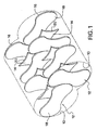
- Figure 1 shows the interior profile 10 (i.e., the inner wetted surface) of a reactor (not shown) with an exploded view of the stirrers 12 and spacers 14.
- the stirrers 12 and corresponding spacers 14 are shown in two parallel groups, each group being mounted on a shaft (not shown).
- the two parallel groups of stirrers and spacers rotate, preferably in opposite directions, into and out of the polymer, thereby forming thin films of polymer on each stirrer and on the interior wall of the reactor by the wiping action, which allows the volatile component to more quickly volatize. It is not only the movement of the stirrers and spacers that wipe the liquid within the reactor into a thin film, but also the fluid mechanics of the liquid in the reactor.
- Figure 1 is an exploded view showing the various components spaced apart, all the stirrers 12 and spacers 14 in one group are actually tightly mounted adjacent one another on a rotating shaft (see Figure 7).
- the two geometric profiles of the stirrers of the present invention are the cycloid profile of Figure 2 and the involute stirrer profile of Figure 3. Both stirrer profile have the characteristic close spacing along the perimeters of mating stirrer elements upon rotation, as shown in Figure 8.
- the peripheral spacing of the stirrers wipes the interior surface 10 of the reactor shell as well as wiping the exposed surface of each stirrer.
- the reactor shell is wiped by the extreme peripheral edge 16 of the rotating stirrers and the face 18 of each stirrer 12 is wiped by the face 18 of adjacent stirrers. Note that the end stirrers at each end of the reactor are spaced from the end plates by an amount approximately equal to the spacing between each stirrer.
- Each stirrer face 18 can be formed from a solid sheet material or from a foraminous member.
- the stirrer face can be formed from metal, plastic or composite materials capable of withstanding the reactor temperature, the physical load of the liquid on the rotating stirrers, and being inert to the liquid. If the face 18 is made from foraminous material, such as metallic screen, the opening must be small enough to permit and support the liquid bridging the opening, such that a thin film of liquid is on each stirrer face 18 as it rotates out of the polymer liquid.
- each stirrer 12 Associated with each stirrer 12 is a spacer 14 to space apart each stirrer from another.
- the spacers 14 are made from a solid material and positioned tightly against each stirrer 12, thereby preventing liquid from flowing between each spacer and stirrer. Only the stirrer face 18 and its peripheral edge 16, and the peripheral edge 20 of each spacer 14, and the interior surface 10 of the reactor 22 are exposed to the liquid.
- each spacer 14 and each stirrer 12 Positioned centrally of each spacer 14 and each stirrer 12 is an aperture 24 through which a shaft 26 (see Figure 7) rotates the stirrers 12 and spacers 14.
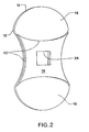
- Figure 2 shows the shape of stirrer 12 in an cycloid profile.
- Figure 3 shows the shape of the stirrer 12 in an involute profile.
- the spacer 14 (in both Figures 2 and 3) is a quadrilateral member, each edge 20 of which is identically configured.
- the thickness of the stirrer 10 depends on many factors such as the load of the polymer in the reactor, the rotating speed of the stirrer, the temperature of the reactor, etc.
- the thickness of each spacer 14 depends on the fluid mechanics of the liquid, as well as the structural rigidity of the stirrers 12. If the stirrers 12 are sufficiently structurally rigid that they do not flex under operating conditions, then the thickness of the spacers depends only on the fluid mechanics of the liquid in the reactor so that a wiping action is achieved.
- the spacers 14 shown in each of Figures 2 and 3 are generally quadrangular in shape, the actual shape depends upon the indexing of each stirrer 12 on the same shaft.
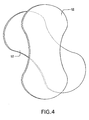
- Figure 4 there is shown a pair of stirrers 12 each of which are index 45° from one another. Note that the spacers 14 do not rotate relative to other stirrers 12 and spacers 14 on the same shaft 26 and the shape of the spacer therefore is the shape of the overlapping area of two adjacent stirrers 12 as shown in Figure 5.
- the spacer 14 shown in Figures 4 and 5 is not quadrilateral since the adjacent stirrers 12 are not indexed 90° from one another as is shown with the spacer and stirrer shown in Figures 1-3.
- the face 18 of stirrer 12 in Figure 2 is longer than the face 18 of the stirrer 12 in Figure 3 because the spacer 14 in Figure 2 does not cover as much area as in Figure 3. This is also illustrated in Figure 6. Note that the corresponding size of the cycloid stirrer 12 versus the involute stirrer shown in Figure 6 means that each must fit within a reactor 22 and specifically within the inner contact surface 10.
- each reactor actually has two shafts 26.
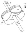
- Each shaft 26 may preferably be a quadrilateral in cross-section for that portion 28 within the reactor upon which is mounted stirrers and spacers, while the portion 30 of the shaft projecting through and outside of the reactor maybe preferably be a different shape, such as cylindrical so that it can easily accommodate conventional seals (not shown and not a distinguishing feature of the present invention).
- the stirrers 12 shown in Figure 7 indicate the 90° indexing.
- Each stirrer has a spacer 14 and each spacer 14 firmly contacts each stirrer 12 with the exception of the spacer at each end of the shaft 26.
- the spacer 14 at each end of the reactor maybe maybe different than the remaining spacers particularly since the fluid mechanics of the liquid are different between the rotating and stirrers and spacer, as compared to the fluid mechanics between two rotating stirrers.
- Figure 8 also illustrates the progression of a pair of stirrers 12, one within each reactor cylinder 32, 34 as the rotation of shafts 26 proceeds, at 0°, 20°, 40°, 60° and 80°.
- the direction of rotation as shown in the 0° position is such the shafts rotate in opposite directions, at the same rotational speed, whereby the stirrers 12 travel toward one another in the bottom of the reactor 22.
- the direction of rotation of the shafts can be oppositely rotated, where the stirrers travel toward one another at the top of the reactor, or rotated in the same direction with one another, either clockwise or counterclockwise, the direction discussed above illustrated in both Figures 8 and 9 is preferred.
- the polymer pool level 36 is shown.
- the rotation of each shaft 26 is illustrated by arrow 38 and 40.
- the central portion of the polymer pool 36 is actually higher than other portions which is caused by the rotation of the shaft 26 and the lifting of the polymer by the multitude of stirrers 12.
- a thin film of polymer 42 is produced in the central most portion of the reactor 22 above the polymer pool 36.
- This polymer film 42 increases the wetted surface area of the reactor thus maximizing the surface area of the reactor.
- various vapor flow paths 44 which allow for the volatile vapor to be eliminated or removed from the reactor 22. Since the inner contact surface 10 of the reactor 22 is wiped with every rotation of shafts 26 (with stirrers 12), these vapor paths do not have any buildup of polymer to block the vapor path in any significant way.
- Figure 10 illustrates the reactor end plates 46 and 48.
- Each end plate 46 and 48 has a vapor takeoff or . vapor outlet 50.
- the vapor outlets 50 When comparing Figures 9 and 10, note that one of the vapor outlets 50 would be positioned on the top left-hand side of the reactor 22, while the other vapor takeoff outlet 50 would be positioned on the righthand side of the reactor. While the vapor outlet(s) 50 can be positioned anywhere within the top most portion of the reactor, having the outlets in the end plates 46, 48 is convenient for fabricating the reactor.
- end plate 46 has an inlet orifice of 52
- reactor end plate 48 has a polymer outlet 54.
- the present reactor primarily designed to be operated continuously could be operated batchwise. The low IV polymer arrives in inlet 52 and exits as a high IV polymer through outlet 54.
- Figure 11 illustrates the intersecting cylinders 32, 34 of the reactor 22 and clearly illustrates a small deviation 56 which is the only surface within the reactor 22 which is not wiped to the same degree as the remaining polymer within the reactor.
- This deviation 56 is only at the outlet end of the reactor and permits the draining of the reactor 22 from both sides and from the lowest point of each cylinder as is clearly shown in Figure 11. It is likewise possible, however, to omit deviation 56 shown in Figure 11, and instead have dual polymer outlets in end plate 48 capable of completely draining even the lowest part of each dual cylindrical 32, 34 of the reactor 22.
- each shaft 26 is rotated in the direction shown by arrows 38 and 40 in Figure 9.
- each stirrer rotates in the same direction, at the same rational speed, as the shaft upon which it is secured, and wipes the inner wetted surface 10 of the reactor 22 exposed to the liquid polymer. Additionally, the rotation of the stirrers contact the polymer and pull it upwardly out of the pool of liquid 36 into a thin film on the face 18 of each stirrer, as well as on the inner contact surface 10 of the reactor 22.
- the thin film of polymer easily permits the volatile component (generally ethylene glycol when polyethylene terephthalate is the polymer, for example) to escape from the polymer, quickly, especially when the reactor is at an elevated temperature (sufficiently high to keep the polymer in liquid form, and yet not so high as to scorch, burn, or otherwise degrade the polymer when it is in a fluid state).
- the volatile component generally ethylene glycol when polyethylene terephthalate is the polymer, for example
- an additional thin polymer surface is produced as illustrated by 42 in Figure 9. This further increases the surface area to reactor volume ratio.
- this polymer film is substantially reduced if the shafts 26 and the stirrers 12 are rotated at a very low rate, or are rotated in any other combinations of rotational directions. Contrarily, if the shafts and stirrers are rotated at too high of a revolution, the polymer is slung throughout the entire reactor and completely blocks the vapor blow path 44, thus defeating the ability of the reactor to remove the volatile component and thereby defeating the ability of the reactor to increase the IV.
- the optimum rotational speed of the shafts must be determined based upon the polymer employed, the IV of the polymer as it is introduced into the reactor, as well as the IV of the polymer exiting the reactor, the temperature of the reactor, etc. Generally, the rotational speed will be between 2-10 rpm (revolutions per minute) and more preferably about 3-5 rpm.
- the spacing between the peripheral edge 16 of the stirrers and the inner surface 10 of the reactor can vary depending on the operating conditions of the reactor, the polymer employed, the fluid mechanics of the polymer at operating conditions (for example to IV), etc., it is generally believed that the spacing can be between 2-10mm, preferably 1-3mm. Likewise the spacing between the peripheral edges 16 of adjacent stirrers on different shafts is believed to be within the above range. Lastly, the spacer thickness and the thickness of the stirrers is also believed to be within the above stated range. Again, all the spacing is dependent upon the conditions mentioned above.
- each stirrer 12 wipes a portion of the inner contact surface 10 of the reactor 22 leaving a portion which is not wiped by that particular perimeter edge.
- the fluid mechanics of the polymer wipes the remaining inner contact surface 10 not wiped by a stirrer 12.
- the faces 18 of each stirrer 12 are wiped by adjacent stirrers on the adjacent shaft, and the spacer edges 20 are also wiped by fluid mechanics of the polymer on the peripheral edge 16 of an adjacent stirrer on the adjacent shaft.
- the drag on the faces by the polymer also serves to wipe the faces.
- the wetted surface area to reactor volume ratio is maximized with the present invention because the spacer thickness is the thinnest possible which still permits polymer to adequately wet-out on each face 18 of the stirrers 12; as well as manufacturing the stirrer thickness as thin as structurally possible, considering the reactor operating conditions.
- the reactor of the present invention maximizes the surface area and reactor volume compared with prior wiped wall type reactors, thus yielding the highest efficiency in converting low I.V. liquid to relatively high I.V. liquid.
- PET entering reactor 22 may have an I.V. from about 0.40 to 0.65, and exit the reactor with an I.V. of 0.90 - 1.15, depending on the operating conditions of the reactor and the polymer employed.
Landscapes
- Chemical & Material Sciences (AREA)
- Organic Chemistry (AREA)
- Chemical Kinetics & Catalysis (AREA)
- Engineering & Computer Science (AREA)
- Mechanical Engineering (AREA)
- Other Resins Obtained By Reactions Not Involving Carbon-To-Carbon Unsaturated Bonds (AREA)
- Physical Or Chemical Processes And Apparatus (AREA)
- Mixers Of The Rotary Stirring Type (AREA)
Description
- This invention relates generally to an apparatus for converting a liquid of low viscosity into a liquid of high viscosity. In particular, the present invention concerns a reactor especially suitable for polycondensation reactions in which a volatile component is removed and a polymeric material of high viscosity is produced while remaining in a liquid state within the reactor. Most specifically, this invention relates to an apparatus for affecting polycondensation to make polyesters or polyamides, such as polyethylene terephthalate or nylon.
- The commercial preparation of most linear condensation polymers, such as polyesters or polyamides, involves heating monomer starting materials to cause progressive condensation with loss of low molecular weight volatile material until the desired molecular weight level is achieved. For example, polyethylene terephthalate, is typically formed from reacting ethylene glycol and either terephthalic acid or its ester equivalent - dimethyl terephthalate: either reaction forms the monomer bis-2-hydroxyethyl terephthalate. By heating the monomer to proper temperatures, generally with increasingly low pressures, the monomer polymerizes with evolution of ethylene glycol until the desired fiber or film forming viscosity desired is achieved. The process is usually carried out in two or more stages with intermediate formation of a low-molecular weight, low-viscosity polymeric'liquid which is then passed through vessels which are maintained at proper temperatures and low pressures to increase the viscosity. These vessels are customarily known as polymer finishers designed to increase the low viscosity polymeric liquid material to a relative high viscosity liquid material. Many of these vessels are "wiped" reactors meaning at least some of the interior reactor surfaces and/or interior components surfaces are "wiped", not by direct contact, but by wiping the liquid on the interior surfaces into a thin film. Such apparatus and process are known from the following U.S. Patents: 3,057,702; 3,248,180; 3,440,019; 3,591,344; 4,801,433 and 5,055,273
- EP 0 715 881 A2 discloses a self-cleaning mixer/ reactor which teaches the use of intermeshing gears wheels (that resemble guillotines) and kneading bars. Kinematic cleaning is understood as being the closet possible approach of the parts of the mixer during rotation, without blocking. Within this reactor, the surfaces of the stirrers are scratching against each other to be cleaned.
- A reactor combining the features of high throughput, having high thin layer surface area, being low in shear and being substantially free of most areas where polymer can buildup is needed.
- As polymer technology has advanced, the industry has demanded polymers having more specific characteristics. For example, the industry demands improved yarns having higher tenacity which means that it is necessary to increase the relative viscosity of the polymer. Conventional reactors suffer several disadvantages in that for higher viscosity polymers, these reactors would have to be excessively large in order to achieve the desired IV and therefore are impractical. Primarily, conventional reactors have several disadvantages such that they are less efficient than the apparatus of the present invention. For example, conventional reactors have a central shaft which tends to restrict the vapor flow of the volatile material to the vacuum exhaust outlet because polymer collects on the surface of the shaft, thereby reducing the effective vapor path. Polymer collection also creates stagnate areas around the shaft ultimately producing a carbonaceous contaminate within the polymeric material. Likewise, polymer buildup can occur in other stagnate regions within the vessel especially in regions of the vessel which are not satisfactorily wiped by an agitator. It is therefore necessary to choose a large surface to volume ratio of the polymer melt and to operate such a reactor under reduced pressure in a way that does not block the vapor path and in a manner which prevents polymer buildup such as by progressively wiping all interior surfaces of the reactor.
- Thus there is a need for a device for continuous polycondensation of melts in which you maximize the surface area to reactor volume ratio, but do not block the vapor flow path and satisfy the criteria of wiping all interior surfaces of the reactor.
- This and other objects are solved by a polycondensation reactor according to claim 1.
- The present invention provides a device for continuous polycondensation of polymer melts which comprises a heatable, cylindrical, horizontal or almost horizontal reactor provided with an inlet at one end, at least one outlet at the other end for the polymer melt, and a vapor outlet. The reactor contains stirrers for the liquid polymer melt adapt to the shape of the reactor which stir the polymer melt and wipe all interior surfaces of the reactor. The space between each stirrer and between the edge of each stirrer and the wall of the reactors is very small, but it is still wiped by the flow mechanics of the polymer. Accordingly, wiped wall reactors of the type disclosed herein do'not "wipe" a surface like a windshield wiper wipes a windshield, i.e. with contact, but instead, the stirrers or wipers spread the polymer into a thin film so that the volatile components volatilize more quickly and exit the reactor through the vapor outlet. Wiping eliminates the buildup of polymeric liquid which becomes carbonaceous material upon becoming stagnate as with conventional reactors. Additionally, the reactor of the present invention achieves a high surface area to reactor volume ratio which spreads the liquid polymer melt into a plurality of thin films allowing the volatile material to volatilize more quickly. The arrangement of the stirrers and the design of the reactor of the present invention are such that there is no blockage of the vapor flow path.
- In accordance with the invention, two parallel shafts having a plurality or stirrers on each shaft are spaced from one another with spacers such that stirrers from one shaft intermesh with stirrers from the parallel shaft with such spacing that the stirrers wipe the polymer melt contact surfaces of one another. Additionally, the stirrers wipe the interior surfaces of the peripheral wall of the reactor. The stirrers of the present invention maximize the surface area to reactor volume ratio without blocking the vapor path and without preventing stagnation of the polymer melt thereby producing a high quality IV polymer (IV means intrinsic viscosity) having relatively low or no carbonaceous material therein.
- Other objects and advantages of the present invention will become apparent upon reading the following detailed description and upon reference to the drawings, in which:
- Figure 1) is a partially perspective, exploded view of the arrangement of the stirrers and spacers within a reactor;
- Figure 2) is a frontal-end view of a cycloid profile stirrer with corresponding spacer;
- Figures 3) is a frontal-end view of another stirrer embodiment in the shape of an involute profile;
- Figure 4) is a frontal-end view of two stirrers indexed at 45°;
- Figure 5) is an end view of the spacer employed when employing 45° stirrer indexing;
- Figure 6) is a cross sectional end view of the shape of both the involute and the cycloid stirrers overlapped for comparison of profile shape;
- Figure 7) is a perspective view of one shaft with several stirrers and spacers mounted thereon in which the stirrers are indexed 90° from one another;
- Figure 8) shows a plurality of stirrers in intermeshing relationship with one another at various degrees of rotation of the parallel shafts;
- Figure 9) is a cross-sectional end view through the middle of the reactor with two parallel shafts and the profiles of the stirrers and the polymer pool level and vapor path being clearly illustrated;
- Figure 10) is a perspective view of the end covers for the reactor of the present invention; and
- Figure 11) is a perspective view of the reactor shell illustrating the deviation necessary for drainage of the polymer from the reactor.
-
- Figure 1 shows the interior profile 10 (i.e., the inner wetted surface) of a reactor (not shown) with an exploded view of the
stirrers 12 andspacers 14. Thestirrers 12 andcorresponding spacers 14 are shown in two parallel groups, each group being mounted on a shaft (not shown). The two parallel groups of stirrers and spacers rotate, preferably in opposite directions, into and out of the polymer, thereby forming thin films of polymer on each stirrer and on the interior wall of the reactor by the wiping action, which allows the volatile component to more quickly volatize. It is not only the movement of the stirrers and spacers that wipe the liquid within the reactor into a thin film, but also the fluid mechanics of the liquid in the reactor. In other words, the viscosity of the liquid aids in wiping the various interior surfaces in the reactor by entertaining any fluid in the area of a moving surface to move along with such surfaces. While Figure 1 is an exploded view showing the various components spaced apart, all thestirrers 12 andspacers 14 in one group are actually tightly mounted adjacent one another on a rotating shaft (see Figure 7). - Turning to Figures 2 and 3, the two geometric profiles of the stirrers of the present invention are the cycloid profile of Figure 2 and the involute stirrer profile of Figure 3. Both stirrer profile have the characteristic close spacing along the perimeters of mating stirrer elements upon rotation, as shown in Figure 8. The peripheral spacing of the stirrers wipes the
interior surface 10 of the reactor shell as well as wiping the exposed surface of each stirrer. The reactor shell is wiped by the extremeperipheral edge 16 of the rotating stirrers and theface 18 of eachstirrer 12 is wiped by theface 18 of adjacent stirrers. Note that the end stirrers at each end of the reactor are spaced from the end plates by an amount approximately equal to the spacing between each stirrer. - In the particular stirrers illustrated by Figures 2 and 3 each
stirrer 12 as twofaces 18, the outerperipheral edge 16 of which is in close spaced relationship to theperipheral edge 16 of an adjacent stirrer as shown in Figure 1. Eachstirrer face 18 can be formed from a solid sheet material or from a foraminous member. For example, the stirrer face can be formed from metal, plastic or composite materials capable of withstanding the reactor temperature, the physical load of the liquid on the rotating stirrers, and being inert to the liquid. If theface 18 is made from foraminous material, such as metallic screen, the opening must be small enough to permit and support the liquid bridging the opening, such that a thin film of liquid is on each stirrer face 18 as it rotates out of the polymer liquid. - Associated with each
stirrer 12 is aspacer 14 to space apart each stirrer from another. Thespacers 14 . are made from a solid material and positioned tightly against eachstirrer 12, thereby preventing liquid from flowing between each spacer and stirrer. Only thestirrer face 18 and itsperipheral edge 16, and theperipheral edge 20 of eachspacer 14, and theinterior surface 10 of thereactor 22 are exposed to the liquid. - Positioned centrally of each
spacer 14 and eachstirrer 12 is anaperture 24 through which a shaft 26 (see Figure 7) rotates thestirrers 12 andspacers 14. - Figure 2 shows the shape of
stirrer 12 in an cycloid profile. Figure 3 shows the shape of thestirrer 12 in an involute profile. Note that the spacer 14 (in both Figures 2 and 3) is a quadrilateral member, eachedge 20 of which is identically configured. The thickness of thestirrer 10 depends on many factors such as the load of the polymer in the reactor, the rotating speed of the stirrer, the temperature of the reactor, etc. The thickness of eachspacer 14 depends on the fluid mechanics of the liquid, as well as the structural rigidity of thestirrers 12. If thestirrers 12 are sufficiently structurally rigid that they do not flex under operating conditions, then the thickness of the spacers depends only on the fluid mechanics of the liquid in the reactor so that a wiping action is achieved. - Although the
spacers 14 shown in each of Figures 2 and 3 are generally quadrangular in shape, the actual shape depends upon the indexing of eachstirrer 12 on the same shaft. Turning to Figure 4, there is shown a pair ofstirrers 12 each of which are index 45° from one another. Note that thespacers 14 do not rotate relative toother stirrers 12 andspacers 14 on thesame shaft 26 and the shape of the spacer therefore is the shape of the overlapping area of twoadjacent stirrers 12 as shown in Figure 5. Thus thespacer 14 shown in Figures 4 and 5 is not quadrilateral since theadjacent stirrers 12 are not indexed 90° from one another as is shown with the spacer and stirrer shown in Figures 1-3. - When comparing the geometric profile of each of the
stirrers 12 shown in Figures 2 and 3, and when noting that one of the aims of the present invention is to maximize the surface area of the components of the reactor which contact the liquid, it is clear that the cycloid profile possesses greater surface area as compared to theinvolute stirrer 12, as shown in Figure 6. Thecycloid stirrer 12 provides 18% more surface area which contacts the liquid than a corresponding involute stirrer. Primarily, this is due to the spacer profile of the cycloid spacer versus the involute spacer. Specifically, theface 18 ofstirrer 12 in Figure 2 is longer than theface 18 of thestirrer 12 in Figure 3 because thespacer 14 in Figure 2 does not cover as much area as in Figure 3. This is also illustrated in Figure 6. Note that the corresponding size of thecycloid stirrer 12 versus the involute stirrer shown in Figure 6 means that each must fit within areactor 22 and specifically within theinner contact surface 10. - As illustrated in Figure 7, a plurality of stirrers and spacers are mounted for rotation on
shaft 26. Each reactor actually has twoshafts 26. Eachshaft 26 may preferably be a quadrilateral in cross-section for thatportion 28 within the reactor upon which is mounted stirrers and spacers, while theportion 30 of the shaft projecting through and outside of the reactor maybe preferably be a different shape, such as cylindrical so that it can easily accommodate conventional seals (not shown and not a distinguishing feature of the present invention). Thestirrers 12 shown in Figure 7 indicate the 90° indexing. Each stirrer has aspacer 14 and eachspacer 14 firmly contacts eachstirrer 12 with the exception of the spacer at each end of theshaft 26. Thespacer 14 at each end of the reactor maybe maybe different than the remaining spacers particularly since the fluid mechanics of the liquid are different between the rotating and stirrers and spacer, as compared to the fluid mechanics between two rotating stirrers. - The 90° indexing of the
cycloid stirrers 12 is more clearly shown in Figure 8, in cross-section.Reactor 22 is actually two intersectingcylinders inner contact surface 10 of eithercylinder reactor 22 has a diameter which is slightly larger than the length of astirrer 12. - Figure 8 also illustrates the progression of a pair of
stirrers 12, one within eachreactor cylinder shafts 26 proceeds, at 0°, 20°, 40°, 60° and 80°. Note that the direction of rotation as shown in the 0° position, is such the shafts rotate in opposite directions, at the same rotational speed, whereby thestirrers 12 travel toward one another in the bottom of thereactor 22. While it is contemplated that the direction of rotation of the shafts can be oppositely rotated, where the stirrers travel toward one another at the top of the reactor, or rotated in the same direction with one another, either clockwise or counterclockwise, the direction discussed above illustrated in both Figures 8 and 9 is preferred. - As shown in Figure 8, the progression of the stirrers of any degree of shaft rotation permits many open spaces for vapor flow. Also, one
peripheral edge 16 of a stirrer "wipes" theperipheral edge 16 of an . adjacent stirrer. Because of fluid mechanics, the entireinner contact surface 10 ofreactor 22 as well as all exposed surfaces of thestirrers 12 andspacers 14 are wiped such that only a thin film of liquid remains. - In Figure 9, the
polymer pool level 36 is shown. The rotation of eachshaft 26 is illustrated byarrow polymer pool 36 is actually higher than other portions which is caused by the rotation of theshaft 26 and the lifting of the polymer by the multitude ofstirrers 12. Also note, that as eachstirrer 12 rotates from the position shown in Figure 9 in the directions illustrated byarrows polymer 42 is produced in the central most portion of thereactor 22 above thepolymer pool 36. Thispolymer film 42 increases the wetted surface area of the reactor thus maximizing the surface area of the reactor. Also illustrated in Figure 9 are variousvapor flow paths 44 which allow for the volatile vapor to be eliminated or removed from thereactor 22. Since theinner contact surface 10 of thereactor 22 is wiped with every rotation of shafts 26 (with stirrers 12), these vapor paths do not have any buildup of polymer to block the vapor path in any significant way. - Figure 10 illustrates the
reactor end plates end plate vapor outlet 50. When comparing Figures 9 and 10, note that one of thevapor outlets 50 would be positioned on the top left-hand side of thereactor 22, while the othervapor takeoff outlet 50 would be positioned on the righthand side of the reactor. While the vapor outlet(s) 50 can be positioned anywhere within the top most portion of the reactor, having the outlets in theend plates vapor outlets 50,end plate 46 has an inlet orifice of 52, andreactor end plate 48 has apolymer outlet 54. The present reactor, primarily designed to be operated continuously could be operated batchwise. The low IV polymer arrives ininlet 52 and exits as a high IV polymer throughoutlet 54. - Figure 11 illustrates the intersecting
cylinders reactor 22 and clearly illustrates asmall deviation 56 which is the only surface within thereactor 22 which is not wiped to the same degree as the remaining polymer within the reactor. Thisdeviation 56 is only at the outlet end of the reactor and permits the draining of thereactor 22 from both sides and from the lowest point of each cylinder as is clearly shown in Figure 11. It is likewise possible, however, to omitdeviation 56 shown in Figure 11, and instead have dual polymer outlets inend plate 48 capable of completely draining even the lowest part of each dual cylindrical 32, 34 of thereactor 22. - In operation, polymer is introduced into the
reactor 22 through thepolymer inlet 52 and the amount of polymer exiting throughoutlet 54 is controlled in such a way as to produce apolymer pool 36. Preferably, eachshaft 26 is rotated in the direction shown byarrows surface 10 of thereactor 22 exposed to the liquid polymer. Additionally, the rotation of the stirrers contact the polymer and pull it upwardly out of the pool ofliquid 36 into a thin film on theface 18 of each stirrer, as well as on theinner contact surface 10 of thereactor 22. The thin film of polymer easily permits the volatile component (generally ethylene glycol when polyethylene terephthalate is the polymer, for example) to escape from the polymer, quickly, especially when the reactor is at an elevated temperature (sufficiently high to keep the polymer in liquid form, and yet not so high as to scorch, burn, or otherwise degrade the polymer when it is in a fluid state). Likewise, it may be preferable to introduce a vacuum through thevapor outlet 50 to further increase the removal of the volatile component. As each stirrer pulls away from its corresponding adjacent stirrer an additional thin polymer surface is produced as illustrated by 42 in Figure 9. This further increases the surface area to reactor volume ratio. However, this polymer film is substantially reduced if theshafts 26 and thestirrers 12 are rotated at a very low rate, or are rotated in any other combinations of rotational directions. Contrarily, if the shafts and stirrers are rotated at too high of a revolution, the polymer is slung throughout the entire reactor and completely blocks thevapor blow path 44, thus defeating the ability of the reactor to remove the volatile component and thereby defeating the ability of the reactor to increase the IV. The optimum rotational speed of the shafts must be determined based upon the polymer employed, the IV of the polymer as it is introduced into the reactor, as well as the IV of the polymer exiting the reactor, the temperature of the reactor, etc. Generally, the rotational speed will be between 2-10 rpm (revolutions per minute) and more preferably about 3-5 rpm. - Although the spacing between the
peripheral edge 16 of the stirrers and theinner surface 10 of the reactor can vary depending on the operating conditions of the reactor, the polymer employed, the fluid mechanics of the polymer at operating conditions (for example to IV), etc., it is generally believed that the spacing can be between 2-10mm, preferably 1-3mm. Likewise the spacing between theperipheral edges 16 of adjacent stirrers on different shafts is believed to be within the above range. Lastly, the spacer thickness and the thickness of the stirrers is also believed to be within the above stated range. Again, all the spacing is dependent upon the conditions mentioned above. - Thus it can be seen with the rotation of the shafts in opposite directions at the same rotational speed, the
perimeter edge 16 of eachstirrer 12 wipes a portion of theinner contact surface 10 of thereactor 22 leaving a portion which is not wiped by that particular perimeter edge. However, the fluid mechanics of the polymer wipes the remaininginner contact surface 10 not wiped by astirrer 12. The faces 18 of eachstirrer 12 are wiped by adjacent stirrers on the adjacent shaft, and the spacer edges 20 are also wiped by fluid mechanics of the polymer on theperipheral edge 16 of an adjacent stirrer on the adjacent shaft. Additionally, as thefaces 18 of the stirrers pass through thepolymer pool 36, the drag on the faces by the polymer also serves to wipe the faces. Lastly, thedeviation 56 is wiped by action of the flowing polymer out of thereactor 22 throughoutlet 54. Thus, all interior "wetted" surfaces of the reactor which are exposed to the liquid polymer are wiped with each rotation of each shaft. The shaft are designed to be rotated at the same rotational speed but in opposite directions. - The wetted surface area to reactor volume ratio is maximized with the present invention because the spacer thickness is the thinnest possible which still permits polymer to adequately wet-out on each
face 18 of thestirrers 12; as well as manufacturing the stirrer thickness as thin as structurally possible, considering the reactor operating conditions. By creating many thin films of polymer on all interior surfaces within the reactor, the volatile component evaporates or flashes-off as fast as possible, under the operating conditions of the reactor. Thus the reactor of the present invention maximizes the surface area and reactor volume compared with prior wiped wall type reactors, thus yielding the highest efficiency in converting low I.V. liquid to relatively high I.V. liquid. For example,PET entering reactor 22 may have an I.V. from about 0.40 to 0.65, and exit the reactor with an I.V. of 0.90 - 1.15, depending on the operating conditions of the reactor and the polymer employed. - Thus it is apparent that there has been provided with accordance with the invention a reactor that fully satisfies the object, aims, and the advantage as set forth above. While the invention has been described in conjunction with specific embodiments thereof, it is evident that many alternatives modifications and . variation will be apparent to those skilled in the art such as those set forth in Figure 11 or wrapping the reactor in a jacket to heat it as it generally known, or to make each
shaft 26 hollow so that a heating medium can be introduced there through to heat the shaft, stirrers and spacers, and others apparent to those skilled in the art in light of the foregoing description. Accordingly, the present invention is intended to embrace such alternatives, modifications, and variation that falls within the scope of the appended claims.
Claims (12)
- A polycondensation reactor comprising:whereby said stirrers (12) are shaped so as to constantly wipe the surface (10) of said interior chamber, and the edge (16) of an intermeshing stirrer on one shaft wipes the edge of an adjacent stirrer on another shaft, and the intermeshing stirrer wipes between faces (18) of a stirrer to the rear,and a stirrer to the front of the adjacent stirrer.a) a reactor (22) having a substantially horizontally extending interior chamber for polycondensation of a polymer;b) an inlet (52) at one end of the reactor (22) for introducing a low I.V. polymer into said interior chamber;c) at least one outlet (54) for said reactor, opposite said inlet, for extracting a high I.V. polymer from said interior chamber ;d) an outlet (50) in said reactor communicating with said interior chamber for exhausting vapor;e) at least two rotatable shafts (26), mounted substantially horizontally and extending the length of said reactor (22) through said interior chamber ;f) a plurality of stirrers (12) mounted on each of said shafts;g) a plurality of spacers (14) for spacing apart each stirrer on each of said at least two shafts (26) such that said stirrers (12) on one shaft intermesh with said stirrer (12) on another shaft;
- The reactor (22) of claim 1, whereby said plurality of stirrers (12) are shaped as a cycloid.
- The reactor (22) of claim 1, whereby said plurality of stirrers (12) are shaped as an involute.
- The reactor (22) of claim 1, wherein said interior chamber (35) is at least two overlapping cylindrical chambers (32, 34).
- The reactor (22) of claim 1, wherein each of said plurality' of stirrers (12) comprises two contact faces, each face having a front and back surface.
- The reactor (22) of claim 5, wherein each of said stirrer is indexed 90° from the stirrer in front and the stirrer in back, on the same shaft.
- The reactor (22) of claim 6, wherein each of said spacers (14) is shaped in cross-section the same as the cross-section of two overlapping stirrers.
- The reactor (22) of claim 5, wherein each of said stirrer is indexed 45° from the stirrer in front and the stirrer in back, on the same shaft.
- The reactor (22) of claim 5, wherein the stirrers on each shaft are aligned in the same manner.
- The reactor (22) of claim 5, wherein said two rotatable shafts (26) rotate in opposite directions.
- The reactor (22) of claim 10, wherein the said two shafts are positioned in said reactor such that said stirrers overlap one another, thus wiping said front and back surfaces of each contact face.
- The reactor (22) of claim 11, wherein said rotation of said shafts is such that a thin film of polymer is formed when said stirrers rotate away from one another.
Applications Claiming Priority (2)
| Application Number | Priority Date | Filing Date | Title |
|---|---|---|---|
| US784167 | 1997-01-15 | ||
| US08/784,167 US5814282A (en) | 1997-01-15 | 1997-01-15 | High surface intermeshing profile reactor |
Publications (3)
| Publication Number | Publication Date |
|---|---|
| EP0858829A2 EP0858829A2 (en) | 1998-08-19 |
| EP0858829A3 EP0858829A3 (en) | 1999-03-17 |
| EP0858829B1 true EP0858829B1 (en) | 2004-09-22 |
Family
ID=25131564
Family Applications (1)
| Application Number | Title | Priority Date | Filing Date |
|---|---|---|---|
| EP98100207A Expired - Lifetime EP0858829B1 (en) | 1997-01-15 | 1998-01-08 | High surface intermeshing profile reactor |
Country Status (8)
| Country | Link |
|---|---|
| US (1) | US5814282A (en) |
| EP (1) | EP0858829B1 (en) |
| BR (1) | BR9800319A (en) |
| CA (1) | CA2226993C (en) |
| DE (1) | DE69826344T2 (en) |
| ID (1) | ID19508A (en) |
| SG (1) | SG63802A1 (en) |
| TW (1) | TW440464B (en) |
Families Citing this family (7)
| Publication number | Priority date | Publication date | Assignee | Title |
|---|---|---|---|---|
| EP0897742A1 (en) * | 1997-08-12 | 1999-02-24 | Hoechst Research & Technology Deutschland GmbH & Co. KG | High surface intermeshing profile reactor and use thereof |
| KR100677808B1 (en) * | 1999-12-17 | 2007-02-05 | 이 아이 듀폰 디 네모아 앤드 캄파니 | Process for Continuous Production of Polytrimethylene Ether Glycol |
| US6481279B1 (en) | 2000-11-21 | 2002-11-19 | Arteva North America S.A.R.L. | Absolute inventory control by radial force measurement |
| DE602006014528D1 (en) * | 2005-04-18 | 2010-07-08 | Gea Pharma Systems Nv | DEVICE FOR COMPLETING GRANULATION AND METHOD FOR THE COMPLETE GRANULATION OF POWDER MATERIAL |
| DE102005034456B3 (en) * | 2005-07-23 | 2006-11-02 | Zimmer Ag | Device, useful for melting polycondensation of polymers under distance gaseous cleavage products in lying cylindrical reactor with agitating chamber, comprises inlet, outlet, gas channel, and outer- and inner rotor that are in chamber |
| CN114797740B (en) * | 2021-09-30 | 2023-07-07 | 中维化纤股份有限公司 | Reaction kettle for preparing modified nylon material |
| CN118829750A (en) * | 2023-12-13 | 2024-10-22 | 江苏港虹纤维有限公司 | A melt-spun single-reactor high- and low-viscosity PET bicomponent elastic fiber and preparation method thereof |
Family Cites Families (17)
| Publication number | Priority date | Publication date | Assignee | Title |
|---|---|---|---|---|
| US3057702A (en) * | 1953-05-11 | 1962-10-09 | Du Pont | Apparatus for preparation of condensation polymers |
| US3248180A (en) * | 1963-09-09 | 1966-04-26 | Du Pont | Polymer finisher apparatus |
| US3440019A (en) * | 1965-06-01 | 1969-04-22 | Vickers Zimmer Ag | Polycondensation reactor |
| DE1720692B2 (en) * | 1967-07-26 | 1973-07-05 | Farbwerke Hoechst AG, vormals Mei ster Lucius & Brumng, 6000 Frankfurt | DEVICE FOR CONTINUOUS POLYCONDENSATION |
| US3630689A (en) * | 1969-10-30 | 1971-12-28 | Baker Perkins Inc | Apparatus for reacting and devolatilizing prepolymer and like materials |
| US3684458A (en) * | 1970-01-08 | 1972-08-15 | Firestone Tire & Rubber Co | Propulsion and processing apparatus for flowable materials |
| JPS5659824A (en) * | 1979-10-23 | 1981-05-23 | Mitsubishi Gas Chem Co Inc | Continuous polymerization of trioxane |
| US4438072A (en) * | 1982-02-22 | 1984-03-20 | Freeman Chemical Corporation | Continuous stream mixer having variable dwell time chamber with auger |
| DE3430885C2 (en) * | 1984-08-22 | 1986-08-21 | Rudolf P. 7000 Stuttgart Fritsch | Device for the continuous processing of liquids and viscous masses |
| JPS61242636A (en) * | 1985-03-29 | 1986-10-28 | Hitachi Ltd | Reactor |
| JPS62180746A (en) * | 1986-01-31 | 1987-08-08 | Mitsubishi Heavy Ind Ltd | Reaction device |
| WO1988004198A1 (en) * | 1986-12-11 | 1988-06-16 | Heinz Nienhaus | Multi-axial mixing drier or reactor |
| DE3743051A1 (en) * | 1987-12-18 | 1989-06-29 | Davy Mckee Ag | DEVICE FOR TREATING HIGH VISCOSITY SUBSTANCES |
| DE4039943A1 (en) * | 1990-12-14 | 1992-06-17 | Berstorff Gmbh Masch Hermann | METHOD AND DEVICE FOR THE UNIFORM, CONTINUOUS MANUFACTURE OF A RUBBER-BASED AND FINISHED MIXTURE FOR VEHICLE TIRES, DRIVE BELTS, TRANSPORT BELTS AND TECHNICAL RUBBER PRODUCTS IN ONLY ONE MIXING DEVICE |
| DE4126425A1 (en) * | 1991-08-09 | 1993-02-11 | Bayer Ag | COMPLETELY SELF-CLEANING REACTOR / MIXER WITH LARGE USAGE |
| DE4312249C1 (en) * | 1993-04-15 | 1994-03-17 | Inventa Ag | Planetary drive for multi-screw extruder and process - has housing with inner teeth, central shaft sun wheel, screws forming main planetary wheels and intermediate planetary wheels between them |
| EP0715881B1 (en) * | 1994-12-05 | 1998-02-25 | Bayer Ag | Fully self-cleaning mixer/reactor |
-
1997
- 1997-01-15 US US08/784,167 patent/US5814282A/en not_active Expired - Fee Related
-
1998
- 1998-01-08 ID IDP980009A patent/ID19508A/en unknown
- 1998-01-08 DE DE69826344T patent/DE69826344T2/en not_active Expired - Fee Related
- 1998-01-08 EP EP98100207A patent/EP0858829B1/en not_active Expired - Lifetime
- 1998-01-14 CA CA002226993A patent/CA2226993C/en not_active Expired - Fee Related
- 1998-01-14 BR BR9800319-4A patent/BR9800319A/en not_active Application Discontinuation
- 1998-01-15 TW TW087100456A patent/TW440464B/en not_active IP Right Cessation
- 1998-01-15 SG SG1998000108A patent/SG63802A1/en unknown
Also Published As
| Publication number | Publication date |
|---|---|
| EP0858829A2 (en) | 1998-08-19 |
| US5814282A (en) | 1998-09-29 |
| EP0858829A3 (en) | 1999-03-17 |
| TW440464B (en) | 2001-06-16 |
| ID19508A (en) | 1998-07-16 |
| BR9800319A (en) | 1999-09-08 |
| DE69826344T2 (en) | 2005-12-29 |
| CA2226993C (en) | 2005-08-09 |
| CA2226993A1 (en) | 1998-07-15 |
| SG63802A1 (en) | 1999-03-30 |
| DE69826344D1 (en) | 2004-10-28 |
Similar Documents
| Publication | Publication Date | Title |
|---|---|---|
| AU640737B2 (en) | Viscous liquid processor | |
| US5055273A (en) | Apparatus for processing high viscosity materials | |
| US6846103B2 (en) | Apparatus for continuous stirring and process for continuous polycondensation of polymer resin | |
| US5635589A (en) | Process for production of condensation polymers | |
| US3695327A (en) | Wiped thin film evaporation and treatment apparatus | |
| KR900005498B1 (en) | Continuous treatment apparatus for viscous material | |
| CA2226993C (en) | High surface intermeshing profile reactor | |
| EP1251957A1 (en) | Batch polycondensation method and a rotating disc reactor therefor | |
| KR101513457B1 (en) | End reactor | |
| US3248180A (en) | Polymer finisher apparatus | |
| US2964391A (en) | Manufacture of synthetic linear polymers | |
| US5230562A (en) | Viscous liquid processor | |
| EP1824587B1 (en) | Reactor for the treatment of highly viscous plastic melts | |
| US4014525A (en) | Horizontal type continuous pug mill for high viscous material | |
| CN212819836U (en) | High-viscosity polymer polycondensation reactor with helical blade stirrer | |
| JP2000508009A (en) | Polycondensation reaction apparatus and method | |
| EP0896832A1 (en) | High surface intermeshing profile reactor and use thereof | |
| EP0897742A1 (en) | High surface intermeshing profile reactor and use thereof | |
| JP3602958B2 (en) | Horizontal reaction tank | |
| JP4291930B2 (en) | Mixing equipment for highly viscous products | |
| CN218689481U (en) | Final polycondensation reaction kettle | |
| US3686826A (en) | Polymer finisher | |
| EP1369169A2 (en) | Apparatus for continuous stirring and process for continuous polycondensation of polymer resin | |
| JP4144967B2 (en) | Horizontal reactor | |
| US3046099A (en) | Improved polymer finisher apparatus |
Legal Events
| Date | Code | Title | Description |
|---|---|---|---|
| PUAI | Public reference made under article 153(3) epc to a published international application that has entered the european phase |
Free format text: ORIGINAL CODE: 0009012 |
|
| AK | Designated contracting states |
Kind code of ref document: A2 Designated state(s): DE FR GB IT NL |
|
| AX | Request for extension of the european patent |
Free format text: AL;LT;LV;MK;RO;SI |
|
| PUAL | Search report despatched |
Free format text: ORIGINAL CODE: 0009013 |
|
| RHK1 | Main classification (correction) |
Ipc: B01F 7/04 |
|
| AK | Designated contracting states |
Kind code of ref document: A3 Designated state(s): AT BE CH DE DK ES FI FR GB GR IE IT LI LU MC NL PT SE |
|
| AX | Request for extension of the european patent |
Free format text: AL;LT;LV;MK;RO;SI |
|
| RAP1 | Party data changed (applicant data changed or rights of an application transferred) |
Owner name: ARTEVA TECHNOLOGIES S.A.R.L. Owner name: HOECHST AKTIENGESELLSCHAFT |
|
| 17P | Request for examination filed |
Effective date: 19990619 |
|
| RAP1 | Party data changed (applicant data changed or rights of an application transferred) |
Owner name: ARTEVA TECHNOLOGIES S.A.R.L. |
|
| AKX | Designation fees paid |
Free format text: DE FR GB IT NL |
|
| 17Q | First examination report despatched |
Effective date: 20020613 |
|
| GRAP | Despatch of communication of intention to grant a patent |
Free format text: ORIGINAL CODE: EPIDOSNIGR1 |
|
| RIN1 | Information on inventor provided before grant (corrected) |
Inventor name: STIKELEATHER, W. JEFFREY Inventor name: SHAW, GORDON Inventor name: HEY, HARTMUT Inventor name: LOHE,HANS |
|
| GRAS | Grant fee paid |
Free format text: ORIGINAL CODE: EPIDOSNIGR3 |
|
| GRAA | (expected) grant |
Free format text: ORIGINAL CODE: 0009210 |
|
| AK | Designated contracting states |
Kind code of ref document: B1 Designated state(s): DE FR GB IT NL |
|
| REG | Reference to a national code |
Ref country code: GB Ref legal event code: FG4D |
|
| REF | Corresponds to: |
Ref document number: 69826344 Country of ref document: DE Date of ref document: 20041028 Kind code of ref document: P |
|
| RAP2 | Party data changed (patent owner data changed or rights of a patent transferred) |
Owner name: INVISTA TECHNOLOGIES S.AE.R.L. |
|
| REG | Reference to a national code |
Ref country code: GB Ref legal event code: 732E |
|
| NLT2 | Nl: modifications (of names), taken from the european patent patent bulletin |
Owner name: INVISTA TECHNOLOGIES S.A.R.L. |
|
| NLS | Nl: assignments of ep-patents |
Owner name: INVISTA TECHNOLOGIES S.A.R.L. |
|
| ET | Fr: translation filed | ||
| PLBE | No opposition filed within time limit |
Free format text: ORIGINAL CODE: 0009261 |
|
| STAA | Information on the status of an ep patent application or granted ep patent |
Free format text: STATUS: NO OPPOSITION FILED WITHIN TIME LIMIT |
|
| REG | Reference to a national code |
Ref country code: FR Ref legal event code: TP |
|
| 26N | No opposition filed |
Effective date: 20050623 |
|
| PGFP | Annual fee paid to national office [announced via postgrant information from national office to epo] |
Ref country code: GB Payment date: 20051209 Year of fee payment: 9 |
|
| PGFP | Annual fee paid to national office [announced via postgrant information from national office to epo] |
Ref country code: NL Payment date: 20051212 Year of fee payment: 9 |
|
| PGFP | Annual fee paid to national office [announced via postgrant information from national office to epo] |
Ref country code: FR Payment date: 20060104 Year of fee payment: 9 |
|
| PGFP | Annual fee paid to national office [announced via postgrant information from national office to epo] |
Ref country code: IT Payment date: 20060131 Year of fee payment: 9 Ref country code: DE Payment date: 20060131 Year of fee payment: 9 |
|
| PG25 | Lapsed in a contracting state [announced via postgrant information from national office to epo] |
Ref country code: DE Free format text: LAPSE BECAUSE OF NON-PAYMENT OF DUE FEES Effective date: 20070801 |
|
| GBPC | Gb: european patent ceased through non-payment of renewal fee |
Effective date: 20070108 |
|
| NLV4 | Nl: lapsed or anulled due to non-payment of the annual fee |
Effective date: 20070801 |
|
| REG | Reference to a national code |
Ref country code: FR Ref legal event code: ST Effective date: 20070930 |
|
| PG25 | Lapsed in a contracting state [announced via postgrant information from national office to epo] |
Ref country code: GB Free format text: LAPSE BECAUSE OF NON-PAYMENT OF DUE FEES Effective date: 20070108 |
|
| PG25 | Lapsed in a contracting state [announced via postgrant information from national office to epo] |
Ref country code: NL Free format text: LAPSE BECAUSE OF NON-PAYMENT OF DUE FEES Effective date: 20070801 |
|
| PG25 | Lapsed in a contracting state [announced via postgrant information from national office to epo] |
Ref country code: FR Free format text: LAPSE BECAUSE OF NON-PAYMENT OF DUE FEES Effective date: 20070131 |
|
| PG25 | Lapsed in a contracting state [announced via postgrant information from national office to epo] |
Ref country code: IT Free format text: LAPSE BECAUSE OF NON-PAYMENT OF DUE FEES Effective date: 20070108 |