EP0858387B1 - Mold laminate assembly for an injection mold machine - Google Patents
Mold laminate assembly for an injection mold machine Download PDFInfo
- Publication number
- EP0858387B1 EP0858387B1 EP96937781A EP96937781A EP0858387B1 EP 0858387 B1 EP0858387 B1 EP 0858387B1 EP 96937781 A EP96937781 A EP 96937781A EP 96937781 A EP96937781 A EP 96937781A EP 0858387 B1 EP0858387 B1 EP 0858387B1
- Authority
- EP
- European Patent Office
- Prior art keywords
- mold
- laminates
- mounting frame
- laminate assembly
- opening
- Prior art date
- Legal status (The legal status is an assumption and is not a legal conclusion. Google has not performed a legal analysis and makes no representation as to the accuracy of the status listed.)
- Expired - Lifetime
Links
- 238000002347 injection Methods 0.000 title claims abstract description 13
- 239000007924 injection Substances 0.000 title claims abstract description 13
- 238000000465 moulding Methods 0.000 claims abstract description 6
- 230000000712 assembly Effects 0.000 abstract description 22
- 238000000429 assembly Methods 0.000 abstract description 22
- 229920003023 plastic Polymers 0.000 description 4
- 239000000463 material Substances 0.000 description 3
- 238000000034 method Methods 0.000 description 3
- 238000010586 diagram Methods 0.000 description 2
- 230000013011 mating Effects 0.000 description 2
- 229920000426 Microplastic Polymers 0.000 description 1
- 238000004891 communication Methods 0.000 description 1
- 238000010438 heat treatment Methods 0.000 description 1
- 238000001746 injection moulding Methods 0.000 description 1
- 239000008188 pellet Substances 0.000 description 1
- 238000007789 sealing Methods 0.000 description 1
Images







Classifications
-
- B—PERFORMING OPERATIONS; TRANSPORTING
- B29—WORKING OF PLASTICS; WORKING OF SUBSTANCES IN A PLASTIC STATE IN GENERAL
- B29C—SHAPING OR JOINING OF PLASTICS; SHAPING OF MATERIAL IN A PLASTIC STATE, NOT OTHERWISE PROVIDED FOR; AFTER-TREATMENT OF THE SHAPED PRODUCTS, e.g. REPAIRING
- B29C45/00—Injection moulding, i.e. forcing the required volume of moulding material through a nozzle into a closed mould; Apparatus therefor
- B29C45/17—Component parts, details or accessories; Auxiliary operations
- B29C45/26—Moulds
- B29C45/37—Mould cavity walls, i.e. the inner surface forming the mould cavity, e.g. linings
-
- B—PERFORMING OPERATIONS; TRANSPORTING
- B29—WORKING OF PLASTICS; WORKING OF SUBSTANCES IN A PLASTIC STATE IN GENERAL
- B29C—SHAPING OR JOINING OF PLASTICS; SHAPING OF MATERIAL IN A PLASTIC STATE, NOT OTHERWISE PROVIDED FOR; AFTER-TREATMENT OF THE SHAPED PRODUCTS, e.g. REPAIRING
- B29C33/00—Moulds or cores; Details thereof or accessories therefor
- B29C33/30—Mounting, exchanging or centering
- B29C33/301—Modular mould systems [MMS], i.e. moulds built up by stacking mould elements, e.g. plates, blocks, rods
- B29C33/302—Assembling a large number of mould elements to constitute one cavity
-
- B—PERFORMING OPERATIONS; TRANSPORTING
- B29—WORKING OF PLASTICS; WORKING OF SUBSTANCES IN A PLASTIC STATE IN GENERAL
- B29C—SHAPING OR JOINING OF PLASTICS; SHAPING OF MATERIAL IN A PLASTIC STATE, NOT OTHERWISE PROVIDED FOR; AFTER-TREATMENT OF THE SHAPED PRODUCTS, e.g. REPAIRING
- B29C45/00—Injection moulding, i.e. forcing the required volume of moulding material through a nozzle into a closed mould; Apparatus therefor
- B29C45/17—Component parts, details or accessories; Auxiliary operations
- B29C45/26—Moulds
- B29C45/2673—Moulds with exchangeable mould parts, e.g. cassette moulds
-
- B—PERFORMING OPERATIONS; TRANSPORTING
- B29—WORKING OF PLASTICS; WORKING OF SUBSTANCES IN A PLASTIC STATE IN GENERAL
- B29C—SHAPING OR JOINING OF PLASTICS; SHAPING OF MATERIAL IN A PLASTIC STATE, NOT OTHERWISE PROVIDED FOR; AFTER-TREATMENT OF THE SHAPED PRODUCTS, e.g. REPAIRING
- B29C45/00—Injection moulding, i.e. forcing the required volume of moulding material through a nozzle into a closed mould; Apparatus therefor
- B29C45/17—Component parts, details or accessories; Auxiliary operations
- B29C45/26—Moulds
- B29C45/2673—Moulds with exchangeable mould parts, e.g. cassette moulds
- B29C2045/2677—The exchangeable mould parts being combinable or rearrangeable in different ways
-
- B—PERFORMING OPERATIONS; TRANSPORTING
- B29—WORKING OF PLASTICS; WORKING OF SUBSTANCES IN A PLASTIC STATE IN GENERAL
- B29C—SHAPING OR JOINING OF PLASTICS; SHAPING OF MATERIAL IN A PLASTIC STATE, NOT OTHERWISE PROVIDED FOR; AFTER-TREATMENT OF THE SHAPED PRODUCTS, e.g. REPAIRING
- B29C45/00—Injection moulding, i.e. forcing the required volume of moulding material through a nozzle into a closed mould; Apparatus therefor
- B29C45/17—Component parts, details or accessories; Auxiliary operations
- B29C45/26—Moulds
- B29C45/37—Mould cavity walls, i.e. the inner surface forming the mould cavity, e.g. linings
- B29C2045/378—Mould cavity walls, i.e. the inner surface forming the mould cavity, e.g. linings built by a stack of modular elements
-
- Y—GENERAL TAGGING OF NEW TECHNOLOGICAL DEVELOPMENTS; GENERAL TAGGING OF CROSS-SECTIONAL TECHNOLOGIES SPANNING OVER SEVERAL SECTIONS OF THE IPC; TECHNICAL SUBJECTS COVERED BY FORMER USPC CROSS-REFERENCE ART COLLECTIONS [XRACs] AND DIGESTS
- Y10—TECHNICAL SUBJECTS COVERED BY FORMER USPC
- Y10S—TECHNICAL SUBJECTS COVERED BY FORMER USPC CROSS-REFERENCE ART COLLECTIONS [XRACs] AND DIGESTS
- Y10S425/00—Plastic article or earthenware shaping or treating: apparatus
- Y10S425/03—Laminated mold
Definitions
- the present invention relates to injection molds having a mold cavity partly composed of several laminates stacked side by side.
- Molds for making relatively small complex injection molded parts such as electrical connector housings, usually utilize several thin section structures, called laminates, that are stacked side by side to form a portion of the mold cavity within which the part is molded.
- the laminates are arranged in an array in the mold and include mold features that extend into the mold cavity to define features of the molded part which are sometimes quite intricate.
- When assembling the laminates to the mold they are usually stacked side by side and held tightly to eliminate any bowing or warped condition in the individual laminates and then inserted into an opening in the partially assembled mold body. This can be difficult to do because of the very small parts involved and the close quarters of the partially assembled mold.
- the length of the stack of laminates must be very closely controlled so that the stack fits in the mold opening with substantially no end to end play.
- the invention comprises a mold laminate assembly for use in an injection mold for producing a molded part.
- the assembly includes a plurality of mold laminates each of which includes a first end having mold features, an opposite second end, and an intermediate shank between said first and second ends.
- a mounting frame has an opening defined by two side walls and two end walls. The opening has a width for closely receiving the second end of each of the laminates with no appreciable lateral play. The opening has a length for closely receiving the second ends of the plurality of laminates with no appreciable end to end play.
- the laminates are stacked side by side to form an array of laminates within the opening, wherein the mold laminate assembly is adapted to be received within a mold body of an injection mold.
- FIG. 1 a mold machine 10 having a machine frame 12, an A-side frame 14 fixed to the machine frame, and a B-side frame 16 that is coupled to the machine frame so that it can move toward and away from the A-side frame.
- An A-side mold assembly 18 is attached to the A-side frame 14 and a mating B-side mold assembly 20 is attached to the B-side frame, in the usual manner.
- the B-side frame 16 is moved by means of a toggle clamp 22 that is hydraulic or electrical powered.
- a mold material injection system 24 is attached to the machine frame 12 and arranged to inject mold material into the mold cavities in the mated A-side and B-side mold assemblies, as will be explained below.
- the injection system 24 includes a hopper 26 for holding plastic pellets, a rotating screw 28 for feeding the pellets and the molten plastic, heater bands 30 for heating the plastic to a molten state, and a nozzle 32 that directs the molten plastic directly into the A-side mold assembly 18 and into the mold cavities of both the A-side and B-side mold assemblies when the mold is closed.
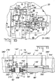
- a block diagram is shown in Figure 2 showing the control functions of the mold machine 10.
- a press controller 42 and a frame controller 44 are interconnected to the machine 10.
- the press controller 42 controls various standard press functions such as opening and closing the mold, commanding the mold material injection system, and ejection of the finished molded parts, indicated in Figure 2 as 46, 48, and 50, respectively.
- the frame controller 44 is interconnected to both the A-side and B-side mold assemblies 18 and 20, respectively, and controls movement of the movable mold bodies when reconfiguring the mold, as will be explained below.
- An input/output terminal 52 is optionally interconnected with the press and frame controllers 42 and 44 so that an operator can manually enter mold configuration commands.
- the A-side mold assembly 18, as shown in Figures 3 and 4 includes first, second and third mold bodies 60, 64, and 62, respectively.
- the first mold body 60 is rigidly attached to a platen 66 that serves as a base for the A-side mold assembly 18.
- the third and second mold bodies 62 and 64 are slidingly coupled to the platen 66, as will be explained.
- the first mold body 60 includes a first surface 68 and a first mold cavity 70 that intersects the surface 68.
- the nozzle 32 enters the center of the first mold body and terminates in a sprue 72 which is in communication with the mold cavity 70 by means of a runner 74 and tunnel gate 76, in the usual manner.
- the third mold body 62 includes a second surface 78 that is parallel to the first surface 68 and opposed thereto, as shown in Figure 4.
- a cutout 80 is formed in the second surface 78 thereby forming two legs 82 and 84.
- the leg 82 includes a second mold cavity 86 and the leg 84 includes a third mold cavity 88, each of which intersects the second surface 78.
- the third mold body 62 is slidingly coupled to the platen 66 by any suitable means so that it is free to move both horizontally and vertically, as viewed in Figures 3 and 4.
- a first linear actuator 90 which in the present example is an air cylinder, is attached to the platen 66 and is slidingly coupled to the third mold body 62 so that upon operation of the actuator 90, the third mold body is made to move in either direction along a horizontal path, as viewed in Figure 3.
- a pair of opposing second and third linear actuators 92 and 94 which are air cylinders in the present example, are secured to mounting brackets 96 and 98 that are attached to the platen 66.
- the piston rods of the two actuators 92 and 94 are coupled to opposite sides of the third mold body 62 through two slide bars 61 and 63 which abut against the third mold body 62 so that the third mold body can be made to move in either direction along a vertical path, as viewed in Figure 3.
- the second mold body 64 includes third and fourth parallel surfaces 100 and 102, respectively.
- a fourth mold cavity 104 extends through the second mold body 64 intersecting the two surfaces 100 and 102.
- the second mold body 64 is slidingly coupled to the platen 66 by any suitable means so that it is free to move both horizontally and vertically, as viewed in Figures 3 and 4.
- Fourth and fifth linear actuators 106 and 108 which in the present example are air cylinders, are attached to the platen 66 and are coupled through a pivoting linkage, not shown, to the second mold body 64 so that upon operation of the actuators, the second mold body 64 is made to move toward the right, as viewed in Figure 3, toward the first actuator 90.
- a pair of opposing sixth and seventh linear actuators 110 and 112 which are air cylinders in the present example, are secured to mounting brackets 96 and 98.
- the piston rods of the two actuators 110 and 112 are slidingly coupled to opposite sides of the second mold body 64 so that by varying the relative pressure in the two actuators, the second mold body can be made to move in either direction along a vertical path, as viewed in Figure 3, and parallel to the first surface 68.
- the second mold body 64 includes two openings 114 and 116 that extend completely through the body 64 intersecting the third and fourth surfaces 100 and 102, for a purpose that will be explained.
- FIG. 5 An array of three contiguous laminate assemblies, a first laminate assembly 140, a second laminate assembly 142, and a third laminate assembly 144, which are associated with the first, second, and third mold bodies 60, 64, and 62, respectively, of the A-side mold assembly 18.
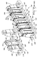
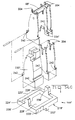
- Each of the laminate assemblies as shown in Figures 6, 7, 8A, 8B, and 8C, includes a rectangular shaped mounting frame and a series of laminates that fit into the mounting frame.
- the laminate assembly 140 includes a mounting frame 146 having a pair of opposite side rails 148 and 150, and a pair of end rails 152 and 154.
- the side and end rails form a closed, encircled opening 156 that is sized to closely receive an end block 160 and a series of laminates 162 that are arranged in three groups, indicated by dashed lines, and end laminates 164 that are arranged on opposite sides of each of the groups of laminates 162, as best seen in Figure 8A.
- the three groups of laminates will mold three contact modules of a single connector housing and the end block 160 will mold an end module on one end of the connector housing.
- Each of the laminates 162 and 164 has a first end with mold features 166 formed thereon that extend into the first mold cavity 70.
- the two end laminates 164 of each group support the two ends of a bridge 168, each group having a separate bridge. A portion of each of the three bridges 168 extends into the first mold cavity 70 to provide additional mold features.
- Each of the laminates 162 and 164 includes a bottom surface 170 opposite its first end and left and right oppositely formed flanges 172 and 174 adjacent opposite ends of the bottom surface, and an intermediate shank 176 between the bottom surface and first end.
- a pair of guide pins 178 are inserted through holes 180 formed in the flanges 172 and 174 of all of the laminates and the end block.
- the stack is then inserted into the opening 156 of the mounting frame 146 with substantially no lateral play between the flanges of the laminates and the side rails 148 and 150 and substantially no end play between the laminates and the end rails 152 and 154.
- the guide pins serve to align the laminates with respect to each other and to hold them together within the mounting frame 146.
- the mounting frame 146 includes a support 158 that extends downwardly from the end rail 152, as shown in Figure 8A, for providing lateral support to the laminates during assembly thereof and to push the laminates together with a portion of the clamping force provided by the injection molding machine as the mold is closed.
- a support 158 that extends downwardly from the end rail 152, as shown in Figure 8A, for providing lateral support to the laminates during assembly thereof and to push the laminates together with a portion of the clamping force provided by the injection molding machine as the mold is closed.
- friction between the laminates and the end rails 152 and 154 is sufficient to hold the stack within the opening 156 during normal handling during the assembly process.
- the end rail 154 may include a downwardly extending portion 186, shown in phantom lines in Figure 8, having a pair of holes 188 into which the ends of the guide pins 178 extend, for positively holding the laminates captive within the mounting frame 146.
- the laminate assembly 142 includes a mounting frame 192 having a pair of opposite side rails 194 and 196, and a pair of end rails 198 and 200.
- the side and end rails form a closed, encircled opening 202 that is sized to closely receive a series of laminates 162 that are arranged in two groups, indicated by dashed lines, and end laminates 164 and 204 that are arranged on opposite sides of the groups of laminates 162.
- the two groups of laminates will mold two contact modules of a connector housing without end modules.
- the mounting frame 192 includes a support 206 that extends downwardly from the end rail 200, and a support 208 that extends downwardly from the end rail 198, as shown in Figure 8B, for providing lateral support to the laminates during assembly thereof.
- Each of the end laminates 204 includes a cutout 210 that receives one of the supports 158 and 206 when the two laminate assemblies 140 and 142 are arranged with their end rails 152 and 200 in engagement, as shown in Figure 7. This arrangement allows the two stacks of laminates in the two assemblies to be contiguous, that is, the end laminate 164 of the assembly 140 is in engagement with the end laminate 204 of the assembly 142.
- the mold features 166 of each of the laminates 162, 164, and 204 of the laminate assembly 142 extend into the fourth mold cavity 104.
- the two end laminates of each group support the two ends of a bridge 168, each of the two groups having a separate bridge in a manner similar to that of the laminate assembly 140.
- a portion of each of the two bridges 168 extends into the fourth mold cavity 104 to provide additional mold features.
- the stack is then inserted into the opening 202 of the mounting frame 192 with substantially no lateral play between the flanges of the laminates and the side rails 194 and 196 and substantially no end play between the laminates and the end rails 198 and 200, in a manner similar to that of the laminate assembly 140.
- the guide pins serve to align the laminates with respect to each other and to hold them together within the mounting frame 192.
- the laminate assembly 144 includes a mounting frame 218 having a pair of opposite side rails 220 and 222, and a pair of end rails 224 and 226.
- the side and end rails form a closed, encircled opening 228 that is sized to closely receive an end block 230 and a series of laminates 162 that are arranged in one group, indicated by dashed lines, and end laminates 164 and 234 that are arranged on opposite sides of the group of laminates 162.
- the single group of laminates will mold one contact module of a connector housing and the end block 160 will mold an end module on one end of the connector housing.
- the mounting frame 218 includes a support 236 that extends downwardly from the end rail 226, and a support 238 that extends downwardly from the end rail 224, as shown in Figure 8C, for providing lateral support to the laminates during assembly thereof.
- Each of the end laminates 234 includes a cutout 240 that receives one of the supports 238 and 208 when the two laminate assemblies 142 and 144 are arranged with their end rails 198 and 226 in engagement, as shown in Figure 7. This arrangement allows the two stacks of laminates in the two assemblies to be contiguous, that is, the end laminate 164 of the assembly 142 is in engagement with the end laminate 234 of the assembly 144.
- the mold features 166 of each of the laminates 162, 164, and 234 of the laminate assembly 142 extend into the third mold cavity 88.
- the two end laminates 164 and 234 of the group support the two ends of a bridge 168 in a manner similar to that of the laminate assembly 140.
- a portion of the bridge 168 extends into the third mold cavity 88 to provide additional mold features.
- the stack is then inserted into the opening 228 of the mounting frame 146 with substantially no lateral play between the flanges of the laminates and the side rails 220 and 222 and substantially no end play between the laminates and the end rails 224 and 226, in a manner similar to that of the laminate assembly 140.
- the guide pins serve to align the laminates with respect to each other and to hold them together within the mounting frame 218.
- friction between the laminates and the end rails 224 and 226 is sufficient to hold the stack within the opening 228 during normal handling during the assembly process.
- the end rail 224 may include a downwardly extending portion 246, shown in phantom lines in Figure 8C, having a pair of holes 248 into which the ends of the guide pins 242 extend, for positively holding the laminates captive within the mounting frame 218.
- the two mounting frames 192 and 218 include pairs of mounting lugs 250 and 252, respectively, extending from their side rails in a direction opposite that of the supports 208 and 236, as best seen in Figures 8B and 8C. These mounting lugs 250 and 252 are used to secure the laminate assemblies 142 and 144 in their respective mold bodies 64 and 62, as shown in Figure 5.
- the mold body 64 includes a cutout 254 having a shoulder 256 against which the mounting lugs 250 are secured by means of a clamp 258.
- a screw 260 is threaded into a hole in the mold body 64 to force the clamp against the mounting lugs 250, as shown in Figure 5.
- Left and right mold pieces 262 and 264 of the mold body 64 include tapered surfaces 266 and 268, respectively, that engage similar tapered surfaces 270 and 272 on opposite sides of the shanks 176 of all of the laminated 162, 164, and 204 of the laminate assembly 142 and precisely align them with respect to the mold cavity 104 and secure them in the mold body 64, as best seen in Figure 6.
- the mold body 62 includes a cutout 274 having a shoulder 276 against which the mounting lugs 252 of the mounting frame 218 are secured by means of a clamp 258 and screw 260, as shown in Figure 5.
- left and right mold pieces 278 and 280 of the mold body 62 are arranged to engage the tapered surfaces of the laminates 162, 164, 234, and the end block 230, for alignment and to secure them in the mold body 64, in a manner similar to that of the mold pieces 262 and 264.
- the mold body 62 includes a mold cavity 86 in addition to the mold cavity 88 which includes a mounting frame 282 similar to the mounting frame 218, however, containing only an end block 230 without laminates, as best seen in Figure 7.
- This mold cavity 86 is used in conjunction with a mating mold cavity, as will be described below, to form an end module onto the connector housing being molded.
- the end rail 154 of the mounting frame 146 includes a shoulder 288 that engages a shoulder 290 formed in the mold body 60, as best seen in Figure 5.
- Left and right mold pieces 292 and 294 of the mold body 60 are arranged to engage the tapered surfaces of the laminates 162, 164, and the end block 160, for alignment and to secure them in the mold body 60, in a manner similar to that of the mold pieces 262 and 264.
- the mold pieces 292 and 294 include portions 296 that extend adjacent the end surface 298 of the end rail 154 and confine the rail between the portions 296 and the shoulder 290 without play.
- the mold bodies 60, 62, and 64 can be separated during the course of automatically reconfiguring the mold without the end laminates of the three laminate assemblies 140, 142, and 144 falling out of position or becoming dislodged in any way.
- the B-side mold assembly 20 as viewed in Figures 9 and 10, have first, second and third mold bodies that mate with the first, second and third mold bodies 60, 64, and 62 of the A-side assembly 18, and have similar identifying part numbers that are primed. That is, the first, second and third mold bodies of the B-side are identified by the part numbers 60', 64', and 62', respectively. Additionally, other features of the B-side mold assembly that have substantially similar corresponding features on the A-side will be identified with a primed version of the A-side part number, even though the corresponding features may be somewhat different.
- the mold bodies 60', 64', and 62' include laminate assemblies 140', 142', and 144', respectively, that are similar in structure to and mate with the laminate assemblies 140, 142, and 144 when the mold is closed for molding a connector housing.
- the laminate assemblies 140' 142' and 144' include respective side rails 148', 150', 194', 196', 220', 222' and end rails 152', 154', 198', 200', 224', 226' that encircle respective openings 156', 202', 228'.
- Laminates 162' and end laminates 164', 204', 234' are arranged in three groups along with an end block 160' to be received in the opening 156', as shown in Figure 14A, two groups to be received in the opening 202', as shown in Figure 14B, and in a single group along with an end block 230' to be received in the opening 228', as shown in Figure 14C, in a manner similar to their counterparts in the laminate assemblies 140, 142, and 144.
- the mold body 62' includes a mold cavity 86' in addition to the mold cavity 88' which includes a mounting frame 282' similar to the mounting frame 218', however, containing only an end block 230' without laminates, as best seen in Figure 13.
- This mold cavity 86' is used in conjunction with the mold cavity 86 to form an end module onto the connector housing being molded.
- the two end laminates 164 of each group support the two ends of a bridge 306, each group having a separate bridge.
- each of the three bridges 306 of the laminate assembly 140' extends into the first mold cavity 70', while portions of the bridges 306 of the laminate assemblies 142' and 144' extend into respective mold cavities 104' and 88', to provide additional mold features in these mold cavities.
- the mold cavities 70', 86', 88', and 104' are actually mold volumes that surround and include the mold features 304 and project into respective mold cavities 70, 86, 88, and 104. However, these mold volumes will be referred to herein as mold cavities.
- the mold features 304 of the laminates in the laminate assemblies 140', 142', and 144' may have a different shape than the mold features 166 in the laminate assemblies 140, 142, and 144.
- the third and second mold bodies 62' and 64' are arranged to move both horizontally and vertically, as viewed in Figure 9, in a manner similar to the mold bodies 62 and 64, by means of first, second, third, fourth, fifth, sixth, and seventh actuators 90', 92', 94', 106', 108', 110', and 112', respectively.
- the outer surfaces of the A-side mold bodies 60, 62, and 64 are mutually coplanar and are collectively identified by the number 130 in Figure 1, this collective surface being the parting line of the mold.
- the opposing surfaces of the B-side mold bodies 60', 62', and 64' are also mutually coplanar and parallel with the surface 130 and are collectively identified by the number 132 in Figure 1.
- the collective surfaces 130 and 132 form a part line and are in sealing mated engagement during the actual molding process.
- the second and third actuators 92 and 94 are operated to move the third mold body 62 downwardly, as viewed in Figure 16, so that the mold cavity 88 is in proper alignment with the mold cavity 104.
- the first actuator 90 is then operated to move the third mold body 62 into mated engagement with the second mold body 64.
- the toggle clamp 22 is then operated to close the mold and the injection system 24 operated to inject molten plastic into the mated mold cavities.
- the third and second mold bodies 62 and 64 must be moved to the position shown in Figure 17. This is done by first opening the mold by operating the toggle clamp 22 and then operating the first actuator 90 to move the third mold body 62 away from the second mold body 64.
- the fourth and fifth actuators 106 and 108 are operated to move the second mold body 64 to the left, as viewed in Figure 16, out of engagement with the first mold body 60 and then the sixth and seventh actuators 110 and 112 are operated to move the second mold body upwardly so the opening 230, shown in Figure 16, is in centered alignment with first mold cavity 70.
- the first actuator 90 is then operated to move the second mold body 64 to the right, as viewed in Figure 17, and the third mold body 62 into mated engagement with the first mold body 60, to the position shown in Figure 17, with the mold cavities 70 and 88 in mated engagement.
- the third mold body 62 must be moved to the position shown in Figure 18.
- any number of mold bodies, including a single mold body, may be advantageously utilized in the practice of the present invention. Additionally, a single laminate assembly may be utilized in combination with one or more mold bodies, or more than one laminate assembly may be used therewith, independent of whether the mold bodies are movable or reconfigurable.
- An important advantage of the present invention is that the laminate assembly can be assembled on a workbench independent of the mold and then easily assembled to the mold as a subassembly. Further, the laminate assembly remains intact when adjacent mold bodies having contiguous mold cavities are separated during automatic reconfiguration.
Landscapes
- Engineering & Computer Science (AREA)
- Mechanical Engineering (AREA)
- Manufacturing & Machinery (AREA)
- Moulds For Moulding Plastics Or The Like (AREA)
- Injection Moulding Of Plastics Or The Like (AREA)
Abstract
Description
- The present invention relates to injection molds having a mold cavity partly composed of several laminates stacked side by side.
- Molds for making relatively small complex injection molded parts, such as electrical connector housings, usually utilize several thin section structures, called laminates, that are stacked side by side to form a portion of the mold cavity within which the part is molded. The laminates are arranged in an array in the mold and include mold features that extend into the mold cavity to define features of the molded part which are sometimes quite intricate. When assembling the laminates to the mold they are usually stacked side by side and held tightly to eliminate any bowing or warped condition in the individual laminates and then inserted into an opening in the partially assembled mold body. This can be difficult to do because of the very small parts involved and the close quarters of the partially assembled mold. The length of the stack of laminates must be very closely controlled so that the stack fits in the mold opening with substantially no end to end play. In the case of reconfigurable molds that can be automatically reconfigured to make different molded parts, such laminates are more difficult to control. This is especially the case at the junction of one of the movable mold bodies with another mold body. Special complex structures are needed to hold the laminates together, at the junction, when the mold bodies are separated for reconfiguring.
- What is needed is a laminate assembly that can be assembled on a workbench independent of the mold and then easily assembled to the mold as a subassembly. Further, the laminate assembly must remain intact when adjacent mold bodies having contiguous mold cavities are separated during automatic reconfiguration.
- The invention comprises a mold laminate assembly for use in an injection mold for producing a molded part. The assembly includes a plurality of mold laminates each of which includes a first end having mold features, an opposite second end, and an intermediate shank between said first and second ends. A mounting frame has an opening defined by two side walls and two end walls. The opening has a width for closely receiving the second end of each of the laminates with no appreciable lateral play. The opening has a length for closely receiving the second ends of the plurality of laminates with no appreciable end to end play. The laminates are stacked side by side to form an array of laminates within the opening, wherein the mold laminate assembly is adapted to be received within a mold body of an injection mold.
- An embodiment of the present invention will now be described with reference to the accompanying drawings, in which:
- FIGURE 1 is a front view of a typical mold machine incorporating the teachings of the present invention;
- FIGURE 2 is a block diagram showing control functions of the machine shown in Figure 1;
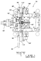
- FIGURE 3 is a cross-sectional view taken along the lines 3-3 in Figure 1;
- FIGURE 4 is an enlarged view of a portion of that of Figure 3;
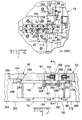
- FIGURE 5 is a cross-sectional view taken along the lines 5-5 in Figure 4;
- FIGURE 6 is a cross-sectional view taken along the lines 6-6 in Figure 5;
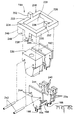
- FIGURE 7 is an isometric view of the A-side laminate assembly shown in Figure 5;
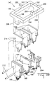
- FIGURES 8A, 8B, and 8C are exploded parts views of the three A-side laminate assemblies shown in Figure 7;
- FIGURE 9 is a cross-sectional view taken along the lines 9-9 in Figure 1;
- FIGURE 10 is an enlarged view of a portion of that of Figure 9;
- FIGURE 11 is a cross-sectional view taken along the lines 11-11 in Figure 10;
- FIGURE 12 is a cross-sectional view taken along the lines 12-12 in Figure 11;
- FIGURE 13 is an isometric view of the B-side laminate assembly shown in Figure 11;
- FIGURES 14A, 14B, and 14C are exploded parts views of the three B-side laminate assemblies shown in Figure 13; and
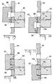
- FIGURES 15 through 18 are schematic representations of the three mold bodies of Figure 4 shown in various operating positions.
-
- There is shown in Figure 1 a
mold machine 10 having amachine frame 12, anA-side frame 14 fixed to the machine frame, and a B-side frame 16 that is coupled to the machine frame so that it can move toward and away from the A-side frame. AnA-side mold assembly 18 is attached to theA-side frame 14 and a mating B-side mold assembly 20 is attached to the B-side frame, in the usual manner. The B-side frame 16 is moved by means of atoggle clamp 22 that is hydraulic or electrical powered. A moldmaterial injection system 24 is attached to themachine frame 12 and arranged to inject mold material into the mold cavities in the mated A-side and B-side mold assemblies, as will be explained below. Theinjection system 24 includes ahopper 26 for holding plastic pellets, a rotatingscrew 28 for feeding the pellets and the molten plastic,heater bands 30 for heating the plastic to a molten state, and anozzle 32 that directs the molten plastic directly into theA-side mold assembly 18 and into the mold cavities of both the A-side and B-side mold assemblies when the mold is closed. A block diagram is shown in Figure 2 showing the control functions of themold machine 10. Apress controller 42 and aframe controller 44 are interconnected to themachine 10. Thepress controller 42 controls various standard press functions such as opening and closing the mold, commanding the mold material injection system, and ejection of the finished molded parts, indicated in Figure 2 as 46, 48, and 50, respectively. Theframe controller 44 is interconnected to both the A-side and B-side mold assemblies 18 and 20, respectively, and controls movement of the movable mold bodies when reconfiguring the mold, as will be explained below. An input/output terminal 52 is optionally interconnected with the press andframe controllers - The
A-side mold assembly 18, as shown in Figures 3 and 4, includes first, second andthird mold bodies first mold body 60 is rigidly attached to aplaten 66 that serves as a base for theA-side mold assembly 18. The third andsecond mold bodies platen 66, as will be explained. As best seen in Figure 4, thefirst mold body 60 includes afirst surface 68 and afirst mold cavity 70 that intersects thesurface 68. Thenozzle 32 enters the center of the first mold body and terminates in asprue 72 which is in communication with themold cavity 70 by means of arunner 74 andtunnel gate 76, in the usual manner. - The
third mold body 62 includes asecond surface 78 that is parallel to thefirst surface 68 and opposed thereto, as shown in Figure 4. Acutout 80 is formed in thesecond surface 78 thereby forming twolegs leg 82 includes asecond mold cavity 86 and theleg 84 includes athird mold cavity 88, each of which intersects thesecond surface 78. Thethird mold body 62 is slidingly coupled to theplaten 66 by any suitable means so that it is free to move both horizontally and vertically, as viewed in Figures 3 and 4. A firstlinear actuator 90, which in the present example is an air cylinder, is attached to theplaten 66 and is slidingly coupled to thethird mold body 62 so that upon operation of theactuator 90, the third mold body is made to move in either direction along a horizontal path, as viewed in Figure 3. A pair of opposing second and thirdlinear actuators brackets platen 66. The piston rods of the twoactuators third mold body 62 through twoslide bars third mold body 62 so that the third mold body can be made to move in either direction along a vertical path, as viewed in Figure 3. - The
second mold body 64 includes third and fourthparallel surfaces 100 and 102, respectively. Afourth mold cavity 104 extends through thesecond mold body 64 intersecting the twosurfaces 100 and 102. Thesecond mold body 64 is slidingly coupled to theplaten 66 by any suitable means so that it is free to move both horizontally and vertically, as viewed in Figures 3 and 4. Fourth and fifthlinear actuators platen 66 and are coupled through a pivoting linkage, not shown, to thesecond mold body 64 so that upon operation of the actuators, thesecond mold body 64 is made to move toward the right, as viewed in Figure 3, toward thefirst actuator 90. A pair of opposing sixth and seventhlinear actuators brackets actuators second mold body 64 so that by varying the relative pressure in the two actuators, the second mold body can be made to move in either direction along a vertical path, as viewed in Figure 3, and parallel to thefirst surface 68. Thesecond mold body 64 includes twoopenings 114 and 116 that extend completely through thebody 64 intersecting the third andfourth surfaces 100 and 102, for a purpose that will be explained. - There is shown in Figure 5 an array of three contiguous laminate assemblies, a
first laminate assembly 140, asecond laminate assembly 142, and athird laminate assembly 144, which are associated with the first, second, andthird mold bodies A-side mold assembly 18. Each of the laminate assemblies, as shown in Figures 6, 7, 8A, 8B, and 8C, includes a rectangular shaped mounting frame and a series of laminates that fit into the mounting frame. - The
laminate assembly 140, as best seen in Figure 8A, includes amounting frame 146 having a pair ofopposite side rails end rails end block 160 and a series oflaminates 162 that are arranged in three groups, indicated by dashed lines, and endlaminates 164 that are arranged on opposite sides of each of the groups oflaminates 162, as best seen in Figure 8A. The three groups of laminates will mold three contact modules of a single connector housing and theend block 160 will mold an end module on one end of the connector housing. Each of thelaminates first mold cavity 70. The twoend laminates 164 of each group support the two ends of abridge 168, each group having a separate bridge. A portion of each of the threebridges 168 extends into thefirst mold cavity 70 to provide additional mold features. Each of thelaminates bottom surface 170 opposite its first end and left and right oppositely formedflanges intermediate shank 176 between the bottom surface and first end. When all of thelaminates end block 160 are arranged side by side in a stack, a pair of guide pins 178 are inserted throughholes 180 formed in theflanges opening 156 of the mountingframe 146 with substantially no lateral play between the flanges of the laminates and the side rails 148 and 150 and substantially no end play between the laminates and the end rails 152 and 154. The guide pins serve to align the laminates with respect to each other and to hold them together within the mountingframe 146. The mountingframe 146 includes asupport 158 that extends downwardly from theend rail 152, as shown in Figure 8A, for providing lateral support to the laminates during assembly thereof and to push the laminates together with a portion of the clamping force provided by the injection molding machine as the mold is closed. Usually, friction between the laminates and the end rails 152 and 154 is sufficient to hold the stack within theopening 156 during normal handling during the assembly process. However, theend rail 154 may include a downwardly extendingportion 186, shown in phantom lines in Figure 8, having a pair ofholes 188 into which the ends of the guide pins 178 extend, for positively holding the laminates captive within the mountingframe 146. - The
laminate assembly 142, as best seen in Figure 8B, includes a mountingframe 192 having a pair of opposite side rails 194 and 196, and a pair ofend rails laminates 162 that are arranged in two groups, indicated by dashed lines, and endlaminates laminates 162. The two groups of laminates will mold two contact modules of a connector housing without end modules. The mountingframe 192 includes asupport 206 that extends downwardly from theend rail 200, and asupport 208 that extends downwardly from theend rail 198, as shown in Figure 8B, for providing lateral support to the laminates during assembly thereof. Each of the end laminates 204 includes acutout 210 that receives one of thesupports laminate assemblies end rails end laminate 164 of theassembly 140 is in engagement with theend laminate 204 of theassembly 142. The mold features 166 of each of thelaminates laminate assembly 142 extend into thefourth mold cavity 104. The two end laminates of each group support the two ends of abridge 168, each of the two groups having a separate bridge in a manner similar to that of thelaminate assembly 140. A portion of each of the twobridges 168 extends into thefourth mold cavity 104 to provide additional mold features. When all of thelaminates holes 214 formed in theflanges laminates assembly 142. The stack is then inserted into theopening 202 of the mountingframe 192 with substantially no lateral play between the flanges of the laminates and the side rails 194 and 196 and substantially no end play between the laminates and the end rails 198 and 200, in a manner similar to that of thelaminate assembly 140. The guide pins serve to align the laminates with respect to each other and to hold them together within the mountingframe 192. - Similarly, the
laminate assembly 144, as best seen in Figure 8C, includes a mountingframe 218 having a pair of opposite side rails 220 and 222, and a pair ofend rails end block 230 and a series oflaminates 162 that are arranged in one group, indicated by dashed lines, and endlaminates laminates 162. The single group of laminates will mold one contact module of a connector housing and theend block 160 will mold an end module on one end of the connector housing. The mountingframe 218 includes asupport 236 that extends downwardly from theend rail 226, and asupport 238 that extends downwardly from theend rail 224, as shown in Figure 8C, for providing lateral support to the laminates during assembly thereof. Each of the end laminates 234 includes acutout 240 that receives one of thesupports laminate assemblies end rails end laminate 164 of theassembly 142 is in engagement with theend laminate 234 of theassembly 144. The mold features 166 of each of thelaminates laminate assembly 142 extend into thethird mold cavity 88. The twoend laminates bridge 168 in a manner similar to that of thelaminate assembly 140. A portion of thebridge 168 extends into thethird mold cavity 88 to provide additional mold features. When all of thelaminates end block 230 are arranged side by side in a stack, a pair of guide pins 242 are inserted throughholes 244 formed in theflanges assembly 144. The stack is then inserted into theopening 228 of the mountingframe 146 with substantially no lateral play between the flanges of the laminates and the side rails 220 and 222 and substantially no end play between the laminates and the end rails 224 and 226, in a manner similar to that of thelaminate assembly 140. - The guide pins serve to align the laminates with respect to each other and to hold them together within the mounting
frame 218. Usually, friction between the laminates and the end rails 224 and 226 is sufficient to hold the stack within theopening 228 during normal handling during the assembly process. However, theend rail 224 may include a downwardly extendingportion 246, shown in phantom lines in Figure 8C, having a pair ofholes 248 into which the ends of the guide pins 242 extend, for positively holding the laminates captive within the mountingframe 218. - The two mounting
frames lugs supports lugs laminate assemblies respective mold bodies mold body 64 includes acutout 254 having ashoulder 256 against which the mounting lugs 250 are secured by means of aclamp 258. Ascrew 260 is threaded into a hole in themold body 64 to force the clamp against the mountinglugs 250, as shown in Figure 5. Left andright mold pieces mold body 64 include taperedsurfaces shanks 176 of all of the laminated 162, 164, and 204 of thelaminate assembly 142 and precisely align them with respect to themold cavity 104 and secure them in themold body 64, as best seen in Figure 6. Similarly, themold body 62 includes acutout 274 having ashoulder 276 against which the mounting lugs 252 of the mountingframe 218 are secured by means of aclamp 258 and screw 260, as shown in Figure 5. Additionally, left andright mold pieces mold body 62 are arranged to engage the tapered surfaces of thelaminates end block 230, for alignment and to secure them in themold body 64, in a manner similar to that of themold pieces mold body 62 includes amold cavity 86 in addition to themold cavity 88 which includes a mountingframe 282 similar to the mountingframe 218, however, containing only anend block 230 without laminates, as best seen in Figure 7. Thismold cavity 86 is used in conjunction with a mating mold cavity, as will be described below, to form an end module onto the connector housing being molded. - The
end rail 154 of the mountingframe 146 includes ashoulder 288 that engages ashoulder 290 formed in themold body 60, as best seen in Figure 5. Left andright mold pieces mold body 60 are arranged to engage the tapered surfaces of thelaminates end block 160, for alignment and to secure them in themold body 60, in a manner similar to that of themold pieces mold bodies clamp 258 to hold theshoulder 288 of theend rail 154 against theshoulder 290. Instead, themold pieces portions 296 that extend adjacent theend surface 298 of theend rail 154 and confine the rail between theportions 296 and theshoulder 290 without play. - With this arrangement the
mold bodies laminate assemblies - The B-
side mold assembly 20, as viewed in Figures 9 and 10, have first, second and third mold bodies that mate with the first, second andthird mold bodies A-side assembly 18, and have similar identifying part numbers that are primed. That is, the first, second and third mold bodies of the B-side are identified by the part numbers 60', 64', and 62', respectively. Additionally, other features of the B-side mold assembly that have substantially similar corresponding features on the A-side will be identified with a primed version of the A-side part number, even though the corresponding features may be somewhat different. As shown in Figures 11, 12, 13, and 14, The mold bodies 60', 64', and 62' include laminate assemblies 140', 142', and 144', respectively, that are similar in structure to and mate with thelaminate assemblies laminate assemblies mold cavity 86' in addition to the mold cavity 88' which includes a mounting frame 282' similar to the mounting frame 218', however, containing only an end block 230' without laminates, as best seen in Figure 13. Thismold cavity 86' is used in conjunction with themold cavity 86 to form an end module onto the connector housing being molded. The twoend laminates 164 of each group support the two ends of abridge 306, each group having a separate bridge. A portion of each of the threebridges 306 of the laminate assembly 140' extends into the first mold cavity 70', while portions of thebridges 306 of the laminate assemblies 142' and 144' extend into respective mold cavities 104' and 88', to provide additional mold features in these mold cavities. Note, it will be understood that themold cavities 70', 86', 88', and 104' are actually mold volumes that surround and include the mold features 304 and project intorespective mold cavities bridges 306 possibly having a different shape than thebridges 168, the mold features 304 of the laminates in the laminate assemblies 140', 142', and 144' may have a different shape than the mold features 166 in thelaminate assemblies - The third and second mold bodies 62' and 64' are arranged to move both horizontally and vertically, as viewed in Figure 9, in a manner similar to the
mold bodies A-side mold bodies number 130 in Figure 1, this collective surface being the parting line of the mold. The opposing surfaces of the B-side mold bodies 60', 62', and 64' are also mutually coplanar and parallel with thesurface 130 and are collectively identified by thenumber 132 in Figure 1. Thecollective surfaces - The following is a brief discussion of the operation of the automatic reconfiguring of the
mold machine 10, with reference to Figures 15 through 18 which schematically depict the various mold bodies of the A-side only. It will be understood that when an A-side mold body is moved in actual operation, so is the corresponding B-side mold body. As shown in Figure 15 themold cavities injection system 24. When it is desired to mold a second part utilizing themold cavities toggle clamp 22 and then operating thefirst actuator 90 to move thethird mold body 62 away from thesecond mold body 64 . The second andthird actuators third mold body 62 downwardly, as viewed in Figure 16, so that themold cavity 88 is in proper alignment with themold cavity 104. Thefirst actuator 90 is then operated to move thethird mold body 62 into mated engagement with thesecond mold body 64. Thetoggle clamp 22 is then operated to close the mold and theinjection system 24 operated to inject molten plastic into the mated mold cavities. When it is desired to mold a third part utilizing themold cavities second mold bodies toggle clamp 22 and then operating thefirst actuator 90 to move thethird mold body 62 away from thesecond mold body 64. The fourth andfifth actuators second mold body 64 to the left, as viewed in Figure 16, out of engagement with thefirst mold body 60 and then the sixth andseventh actuators opening 230, shown in Figure 16, is in centered alignment withfirst mold cavity 70. Thefirst actuator 90 is then operated to move thesecond mold body 64 to the right, as viewed in Figure 17, and thethird mold body 62 into mated engagement with thefirst mold body 60, to the position shown in Figure 17, with themold cavities mold cavities third mold body 62 must be moved to the position shown in Figure 18. This is done by first opening the mold by operating thetoggle clamp 22 and then operating thefirst actuator 90 to move thethird mold body 62 away from thesecond mold body 64. The second andthird actuators third mold body 62 upwardly, as viewed in Figure 17 until thesecond mold cavity 86 is in alignment with thefirst mold cavity 70. Thefirst actuator 90 is then operated to move thethird mold body 62 into mated engagement with thefirst mold body 60, to the position shown in Figure 18, with themold cavities - While three mold bodies and three laminate assemblies are disclosed herein, two of which are movable, any number of mold bodies, including a single mold body, may be advantageously utilized in the practice of the present invention. Additionally, a single laminate assembly may be utilized in combination with one or more mold bodies, or more than one laminate assembly may be used therewith, independent of whether the mold bodies are movable or reconfigurable.
- An important advantage of the present invention is that the laminate assembly can be assembled on a workbench independent of the mold and then easily assembled to the mold as a subassembly. Further, the laminate assembly remains intact when adjacent mold bodies having contiguous mold cavities are separated during automatic reconfiguration.
Claims (8)
- A mold laminate assembly (140,140', 142,142', 144,144') for use in an injection mold (18, 20) for producing a molded part including a plurality of mold laminates (162,162', 164,164', 204,204', 234,234') each of which includes a first end having mold features (166, 304), an opposite second end, and an intermediate shank (176, 176') between said first and second ends, characterized by:a mounting frame (146,146', 192,192', 218,218') having an opening (156, 156', 202, 202', 228, 228') defined by two side walls (148, 148', 150, 150',194, 194', 196, 196', 220, 220', 222, 222') and two end walls (152, 152', 154, 154', 198, 198', 200, 200', 224, 224'), 226, 226'), said opening having a width for closely receiving said second end of each of said laminates with no appreciable lateral play, and said opening having a length for closely receiving said second ends of said plurality of laminates with no appreciable end to end play, said laminates being stacked side by side to form an array of laminates within said opening,wherein said mold laminate assembly is adapted to be received within a mold body (60, 60', 62, 62' and 64, 64') of an injection mold (18, 20).
- The mold laminate assembly (140,140', 142,142', 144,144') according to claim 1 characterized in that said mounting frame (146, 146', 192, 192', 218, 218') comprises two oppositely disposed side rails (148, 148', 150, 150',194, 194', 196, 196', 220, 220', 222, 222'), a first end rail (152, 152', 198, 198', 224, 224') attached to one end of each of said two side rails, and a second end rail (154, 154', 200, 200', 226, 226') attached to the other end of each of said two side rails thereby forming a continuous structure completely surrounding said opening (156, 156', 202, 202', 228, 228').
- The mold laminate assembly (140,140', 142,142', 144,144') according to claim 2 characterized in that said mounting frame (146, 146', 192, 192', 218, 218') includes a projection (152, 152') extending from one side thereof and adapted to engage said mold body (60, 60', 62, 62' and 64, 64') for positioning said mold laminate assembly therewithin.
- The mold laminate assembly (140,140', 142,142', 144,144') according to claim 3 where said mounting frame (146, 146', 192, 192', 218, 218') includes a flange (158, 158', 208, 208', 238, 238') extending from said first end rail and arranged to engage one of said plurality of laminates and urge said plurality of laminates into square alignment with respect to said two side rails of said mounting frame.
- The mold laminate assembly (140,140', 142,142', 144,144') according to claim 1 characterized in that each of said plurality of laminates includes a bottom surface (170, 170') and left and right oppositely formed flanges (172, 172', 174, 174') adjacent opposite ends of said bottom surface and a hole (180, 180', 214, 214', 144, 144') formed through each of said left and right flanges, and including a pair of pins (178, 178', 212, 212', 242, 242'), one said pin extending through said holes of at least two of said right flanges and the other said pin extending through said holes of at least two of said left flanges, said pair of pins serving to maintain said plurality of laminates in mutual alignment within said opening (156, 156', 202, 202', 228, 228') of said mounting frame (146, 146', 192, 192', 218, 218').
- The mold laminate assembly (140,140', 142,142', 144,144') according to claim 5 characterized in that one of said pair of pins extends into a hole (188, 188', 248, 248') in said mounting frame (146, 146', 192, 192', 218, 218) thereby holding said plurality of laminates captive to said mounting frame.
- The mold laminate assembly (140,140', 142,142', 144,144') according to claim 1 characterized in that said shank (176, 176') of each of said laminates includes locating surfaces for engaging said mold body (60, 60', 62, 62' and 64, 64') for precisely aligning said laminate within said mold body.
- The mold laminate assembly (140,140', 142,142', 144,144') according to claim 1 characterized by a bridge (168, 168') disposed in engagement with said first end of each of said plurality of laminates, said bridge having mold features thereon that cooperate with said mold features (166, 166') of said plurality of laminates in the molding of said molded part.
Applications Claiming Priority (6)
| Application Number | Priority Date | Filing Date | Title |
|---|---|---|---|
| US709095P | 1995-10-31 | 1995-10-31 | |
| US7090P | 1995-10-31 | ||
| US709P | 1995-10-31 | ||
| US701409 | 1996-08-22 | ||
| US08/701,409 US5783224A (en) | 1995-10-31 | 1996-08-22 | Mold laminate assembly for an injection mold machine |
| PCT/US1996/017273 WO1997016298A1 (en) | 1995-10-31 | 1996-10-29 | Mold laminate assembly for an injection mold machine |
Publications (2)
| Publication Number | Publication Date |
|---|---|
| EP0858387A1 EP0858387A1 (en) | 1998-08-19 |
| EP0858387B1 true EP0858387B1 (en) | 1999-12-22 |
Family
ID=26676492
Family Applications (1)
| Application Number | Title | Priority Date | Filing Date |
|---|---|---|---|
| EP96937781A Expired - Lifetime EP0858387B1 (en) | 1995-10-31 | 1996-10-29 | Mold laminate assembly for an injection mold machine |
Country Status (5)
| Country | Link |
|---|---|
| US (1) | US5783224A (en) |
| EP (1) | EP0858387B1 (en) |
| JP (1) | JPH11514596A (en) |
| DE (1) | DE69605817T2 (en) |
| WO (1) | WO1997016298A1 (en) |
Families Citing this family (13)
| Publication number | Priority date | Publication date | Assignee | Title |
|---|---|---|---|---|
| US7338626B1 (en) | 2002-12-14 | 2008-03-04 | Federal Mogul World Wide, Inc. | High cavitation, low tonnage rubber mold machine and method |
| US7241405B1 (en) | 2003-09-08 | 2007-07-10 | Crain Enterprises, Inc. | Method of renewing a mold block |
| US7204685B1 (en) | 2003-09-08 | 2007-04-17 | Crain Enterprises, Inc. | Modular mold |
| US7497677B1 (en) | 2003-09-08 | 2009-03-03 | Crain Enterprises, Inc. | Mold having modular submold |
| US7500843B2 (en) * | 2004-09-08 | 2009-03-10 | Crain Enterprises, Inc. | Mold system kit |
| DE502006003609D1 (en) * | 2006-07-07 | 2009-06-10 | Rkt Rodinger Kunststoff Techni | Injection mold with lamellar elements |
| JP5342817B2 (en) * | 2008-06-26 | 2013-11-13 | 矢崎総業株式会社 | Mold device and module for electrical connection |
| US8632711B2 (en) | 2010-04-20 | 2014-01-21 | Dell Products L.P. | Method for manufacture of information handling system laminated housings |
| DE102015202116A1 (en) * | 2015-02-06 | 2016-08-11 | Power Plus Communications Ag | Injection molding tool, method for producing a housing part using such an injection molding tool and housing part |
| CN104772859B (en) * | 2015-05-07 | 2017-05-03 | 鸿利达模具科技(中山)有限公司 | Multi-component multi-cavity in-mold welding forming mold |
| JP6164715B1 (en) * | 2016-11-10 | 2017-07-19 | 株式会社ソディック | Cassette mold equipment |
| CN107650341B (en) * | 2017-09-29 | 2024-05-24 | 李金国 | Combined structural die |
| US12318981B2 (en) | 2020-06-03 | 2025-06-03 | Canon Virginia, Inc. | Conveyance apparatus for conveying mold |
Family Cites Families (25)
| Publication number | Priority date | Publication date | Assignee | Title |
|---|---|---|---|---|
| FR59707E (en) * | 1949-03-26 | 1954-07-16 | Mold suitable for casting, as well as for certain shaping of materials such as metals, plastics, any pastes | |
| US3357058A (en) * | 1966-10-31 | 1967-12-12 | Gronemeyer Erich W | Apparatus for injection molding a bristled product |
| US3564660A (en) * | 1968-12-09 | 1971-02-23 | George Darnell | Injection molding machine |
| US3756553A (en) * | 1971-07-09 | 1973-09-04 | Lau Inc | Segmented mold for blower wheels |
| US3807928A (en) * | 1972-03-24 | 1974-04-30 | Monsanto Co | Blow mold improvements |
| US3930780A (en) * | 1973-07-20 | 1976-01-06 | Beatrice Foods Co. | Injection molding apparatus for partitioned containers |
| JPS605164B2 (en) * | 1980-02-05 | 1985-02-08 | キヤニヨン株式会社 | Injection molding machine |
| US4330248A (en) * | 1980-09-15 | 1982-05-18 | Platte Richard L | Mold with adjustable inserts |
| US4303221A (en) * | 1980-11-14 | 1981-12-01 | The Bendix Corporation | Core pin for making a plastic connector shell having an internal keyway |
| US4550006A (en) * | 1981-06-10 | 1985-10-29 | General Electric Company | Method of making a molded part utilizing a liquid injection molding apparatus |
| US4501548A (en) * | 1983-07-18 | 1985-02-26 | Bekum Plastics Machinery Inc. | Label transferring device for blow molding machines |
| JPS60259420A (en) * | 1984-06-06 | 1985-12-21 | Fanuc Ltd | Mold for plastics |
| DE3516175A1 (en) * | 1985-05-06 | 1986-11-06 | Fa. Martin Rudolph, 5620 Velbert | LENGTH ADJUSTABLE BLOW MOLD |
| JPS6362332A (en) * | 1986-09-03 | 1988-03-18 | Nec Corp | Device for manufacturing semiconductor device |
| US4861534A (en) * | 1988-06-29 | 1989-08-29 | International Business Machines Corporation | Method and apparatus for the injection molding of circuit boards |
| US4975041A (en) * | 1989-05-18 | 1990-12-04 | Fries Steven L | Die assembly for die casting a propeller structure |
| IE892171A1 (en) * | 1989-07-06 | 1991-01-16 | Desbury Ltd | A mould for a cable connector |
| FR2651170B1 (en) * | 1989-08-25 | 1992-04-24 | Ecia Equip Composants Ind Auto | MOLD AND ITS MANUFACTURING METHOD FOR OBTAINING MOLDED PARTS. |
| JPH07110506B2 (en) * | 1990-06-29 | 1995-11-29 | 株式会社精工舎 | Injection mold equipment |
| US5217728A (en) * | 1991-06-21 | 1993-06-08 | Amp Incorporated | High density mold |
| US5255889A (en) * | 1991-11-15 | 1993-10-26 | Continental Pet Technologies, Inc. | Modular wold |
| JPH06824A (en) * | 1992-06-18 | 1994-01-11 | Fanuc Ltd | Ejection device of core |
| JP2521008B2 (en) * | 1992-06-30 | 1996-07-31 | 株式会社日本製鋼所 | Injection molding method and injection molding machine |
| CA2099456C (en) * | 1993-06-30 | 1997-02-18 | Italo Caroli | Spacing means for reflex pin block |
| WO1995008416A1 (en) * | 1993-09-20 | 1995-03-30 | Massachusetts Institute Of Technology | Process for rapidly forming laminated dies and said dies |
-
1996
- 1996-08-22 US US08/701,409 patent/US5783224A/en not_active Expired - Fee Related
- 1996-10-29 EP EP96937781A patent/EP0858387B1/en not_active Expired - Lifetime
- 1996-10-29 JP JP9517460A patent/JPH11514596A/en active Pending
- 1996-10-29 DE DE69605817T patent/DE69605817T2/en not_active Expired - Fee Related
- 1996-10-29 WO PCT/US1996/017273 patent/WO1997016298A1/en not_active Ceased
Also Published As
| Publication number | Publication date |
|---|---|
| DE69605817T2 (en) | 2000-05-31 |
| WO1997016298A1 (en) | 1997-05-09 |
| JPH11514596A (en) | 1999-12-14 |
| DE69605817D1 (en) | 2000-01-27 |
| US5783224A (en) | 1998-07-21 |
| EP0858387A1 (en) | 1998-08-19 |
Similar Documents
| Publication | Publication Date | Title |
|---|---|---|
| US5783224A (en) | Mold laminate assembly for an injection mold machine | |
| US5731013A (en) | Reconfigurable mold having travelling separator assist | |
| EP0339642A2 (en) | Mold assembly, and methods of mounting and removing insert thereof, and ejecting the insert | |
| US3838960A (en) | Apparatus for making injection molded articles | |
| WO2004082920A3 (en) | Modular mold change system | |
| JPH0661789B2 (en) | Injection molding method and apparatus | |
| WO2008043003A2 (en) | High cavitation, low tonnage rubber mold machine and method | |
| JP3320193B2 (en) | Cassette mold holder for injection molding | |
| US5711971A (en) | Reconfigurable mold having traveling ejector system | |
| US3978186A (en) | Method for making a partitioned container | |
| EP0669194B1 (en) | Method of and mold for molding product having insert | |
| DE3542840A1 (en) | Moulded tool for injection moulding parts | |
| US20060279023A1 (en) | Precision loader of injection molds | |
| US7361012B2 (en) | Multiple-level stack mold apparatus | |
| JP2000141418A (en) | Cassette type mold device | |
| CN101132897A (en) | Device for receiving a casting mould | |
| CN210651688U (en) | Mould for forming CD sound button cap with one outlet and multiple outlets | |
| JPH0924526A (en) | Manufacture of resin molding and mold for manufacture the same | |
| EP0846047B1 (en) | Reconfigurable mold having travelling ejector system | |
| JPH0426290B2 (en) | ||
| EP4100225B1 (en) | Injection moulding machine with guide rail system for mould box | |
| CN221388846U (en) | Die casting die for automobile pressure control valve | |
| JPH03230928A (en) | Mold unit for injection molding | |
| JP7348158B2 (en) | injection mold | |
| KR100391574B1 (en) | Mold Device for Projection Forming and the Process Utilizing Thereof |
Legal Events
| Date | Code | Title | Description |
|---|---|---|---|
| PUAI | Public reference made under article 153(3) epc to a published international application that has entered the european phase |
Free format text: ORIGINAL CODE: 0009012 |
|
| 17P | Request for examination filed |
Effective date: 19980423 |
|
| AK | Designated contracting states |
Kind code of ref document: A1 Designated state(s): CH DE FR GB LI |
|
| GRAG | Despatch of communication of intention to grant |
Free format text: ORIGINAL CODE: EPIDOS AGRA |
|
| 17Q | First examination report despatched |
Effective date: 19990413 |
|
| GRAG | Despatch of communication of intention to grant |
Free format text: ORIGINAL CODE: EPIDOS AGRA |
|
| GRAH | Despatch of communication of intention to grant a patent |
Free format text: ORIGINAL CODE: EPIDOS IGRA |
|
| GRAH | Despatch of communication of intention to grant a patent |
Free format text: ORIGINAL CODE: EPIDOS IGRA |
|
| GRAA | (expected) grant |
Free format text: ORIGINAL CODE: 0009210 |
|
| RAP1 | Party data changed (applicant data changed or rights of an application transferred) |
Owner name: THE WHITAKER CORPORATION |
|
| AK | Designated contracting states |
Kind code of ref document: B1 Designated state(s): CH DE FR GB LI |
|
| PG25 | Lapsed in a contracting state [announced via postgrant information from national office to epo] |
Ref country code: LI Free format text: LAPSE BECAUSE OF FAILURE TO SUBMIT A TRANSLATION OF THE DESCRIPTION OR TO PAY THE FEE WITHIN THE PRESCRIBED TIME-LIMIT Effective date: 19991222 Ref country code: CH Free format text: LAPSE BECAUSE OF FAILURE TO SUBMIT A TRANSLATION OF THE DESCRIPTION OR TO PAY THE FEE WITHIN THE PRESCRIBED TIME-LIMIT Effective date: 19991222 |
|
| REG | Reference to a national code |
Ref country code: CH Ref legal event code: EP |
|
| REF | Corresponds to: |
Ref document number: 69605817 Country of ref document: DE Date of ref document: 20000127 |
|
| ET | Fr: translation filed | ||
| REG | Reference to a national code |
Ref country code: CH Ref legal event code: PL |
|
| PGFP | Annual fee paid to national office [announced via postgrant information from national office to epo] |
Ref country code: GB Payment date: 20000918 Year of fee payment: 5 |
|
| PGFP | Annual fee paid to national office [announced via postgrant information from national office to epo] |
Ref country code: FR Payment date: 20001009 Year of fee payment: 5 |
|
| PLBE | No opposition filed within time limit |
Free format text: ORIGINAL CODE: 0009261 |
|
| STAA | Information on the status of an ep patent application or granted ep patent |
Free format text: STATUS: NO OPPOSITION FILED WITHIN TIME LIMIT |
|
| 26N | No opposition filed | ||
| PG25 | Lapsed in a contracting state [announced via postgrant information from national office to epo] |
Ref country code: GB Free format text: LAPSE BECAUSE OF NON-PAYMENT OF DUE FEES Effective date: 20011029 |
|
| REG | Reference to a national code |
Ref country code: GB Ref legal event code: IF02 |
|
| GBPC | Gb: european patent ceased through non-payment of renewal fee |
Effective date: 20011029 |
|
| PG25 | Lapsed in a contracting state [announced via postgrant information from national office to epo] |
Ref country code: FR Free format text: LAPSE BECAUSE OF NON-PAYMENT OF DUE FEES Effective date: 20020628 |
|
| REG | Reference to a national code |
Ref country code: FR Ref legal event code: ST |
|
| PGFP | Annual fee paid to national office [announced via postgrant information from national office to epo] |
Ref country code: DE Payment date: 20061130 Year of fee payment: 11 |
|
| PG25 | Lapsed in a contracting state [announced via postgrant information from national office to epo] |
Ref country code: DE Free format text: LAPSE BECAUSE OF NON-PAYMENT OF DUE FEES Effective date: 20080501 |