EP0856813B1 - Method for improving contrast in picture sequences - Google Patents
Method for improving contrast in picture sequences Download PDFInfo
- Publication number
- EP0856813B1 EP0856813B1 EP98101222A EP98101222A EP0856813B1 EP 0856813 B1 EP0856813 B1 EP 0856813B1 EP 98101222 A EP98101222 A EP 98101222A EP 98101222 A EP98101222 A EP 98101222A EP 0856813 B1 EP0856813 B1 EP 0856813B1
- Authority
- EP
- European Patent Office
- Prior art keywords
- histogram
- bin
- picture
- pixel
- distribution
- Prior art date
- Legal status (The legal status is an assumption and is not a legal conclusion. Google has not performed a legal analysis and makes no representation as to the accuracy of the status listed.)
- Expired - Lifetime
Links
Images



Classifications
-
- H—ELECTRICITY
- H04—ELECTRIC COMMUNICATION TECHNIQUE
- H04N—PICTORIAL COMMUNICATION, e.g. TELEVISION
- H04N5/00—Details of television systems
- H04N5/14—Picture signal circuitry for video frequency region
- H04N5/20—Circuitry for controlling amplitude response
-
- G—PHYSICS
- G06—COMPUTING OR CALCULATING; COUNTING
- G06T—IMAGE DATA PROCESSING OR GENERATION, IN GENERAL
- G06T5/00—Image enhancement or restoration
- G06T5/40—Image enhancement or restoration using histogram techniques
-
- G—PHYSICS
- G06—COMPUTING OR CALCULATING; COUNTING
- G06T—IMAGE DATA PROCESSING OR GENERATION, IN GENERAL
- G06T5/00—Image enhancement or restoration
- G06T5/90—Dynamic range modification of images or parts thereof
- G06T5/92—Dynamic range modification of images or parts thereof based on global image properties
-
- G—PHYSICS
- G06—COMPUTING OR CALCULATING; COUNTING
- G06T—IMAGE DATA PROCESSING OR GENERATION, IN GENERAL
- G06T2207/00—Indexing scheme for image analysis or image enhancement
- G06T2207/10—Image acquisition modality
- G06T2207/10016—Video; Image sequence
Definitions
- mapping function is evenly converted from a mapping function 1 producing a complete histogram equalization towards a mapping function 3 (i.e. diameter of the diagram) corresponding to zero strength.
- mapping function 3 i.e. diameter of the diagram
- the attenuated mapping function 2 is located in between these two.
- a general reduction in the equalization strength deteriorates the obtained result as for other picture areas apart from those corresponding to the histogram peak.
- the pictures of a picture sequence are gathered into histograms which are treated in certain fashion for improving the picture contrast, whereafter on the basis of the treated histograms there are formed mapping functions, and the pixel values of the pictures of the picture sequence are then altered on the basis of said functions.
- the histograms are processed so that from each class where the magnitude of values surpasses a given predetermined limit there are cut out values exceeding said limit, which are then redistributed into the histogram, to classes located close to the class under observation.
Landscapes
- Engineering & Computer Science (AREA)
- Physics & Mathematics (AREA)
- General Physics & Mathematics (AREA)
- Theoretical Computer Science (AREA)
- Multimedia (AREA)
- Signal Processing (AREA)
- Image Processing (AREA)
- Facsimile Image Signal Circuits (AREA)
- Picture Signal Circuits (AREA)
- Television Receiver Circuits (AREA)
- Studio Devices (AREA)
Description
- The invention relates to adjusting contrast in television pictures and other natural picture sequences, and more accurately to improving a single picture by modifying the histogram in a given fashion and to improving the picture sequence contrast by adjusting the method of modifying the histograms of successive pictures.
- Histogram equalization is a known method for maximizing picture contrast. A histogram is the distribution of the brightness values of a picture, i.e. in order to create a histogram, the brightness values of a picture are grouped into classes, and the number of brightness values belonging to each class is calculated. The width of a class can vary according to the purpose of use of the histogram. When narrowest, the interval of the extreme values of a class can be one quantizing interval of a pixel value, in which case the histogram is essentially the same as the pixel value distribution. An example of a histogram is illustrated in Figure 1, where the brightness values of an exemplary picture are divided into 256 classes.
- In histogram equalization, the histogram is turned into a so-called mapping function whereby the brightness values of the source picture are converted into brightness values of the target picture, so that the histogram measured of the brightness values of the target picture is equalized. Converting with the mapping function corresponds to a non-linear amplification of an input signal, i.e. to expanding of certain intervals of the brightness distribution and reducing other intervals. In order to equalize a histogram, those areas in the pixel value distribution are expanded which in the original picture contain a lot of values, i.e. at these spots the mapping function must be sharp. A mapping function formed of the histogram of Figure 1 and producing histogram equalization is illustrated in Figure 2 (curve 1).
- The wide, equally bright areas of the picture are seen as high and narrow peaks in the original histogram. The higher the peak of an original histogram, the wider in the target picture pixel value range are the original values contained in the peak expanded, wherefore the tone differences contained in such a picture area are disproportionately amplified. Such a spot is seen in the
mapping function 1 of Figure 2 as a steeply rising part. Thus the height of the histogram peak can be directly compared with the amplification of the pixel values in said area. - Histogram equalization is not as such directly suited to natural pictures so well as for instance to improving contrast in medical pictures, because histogram equalization makes pictures look unnatural. Thus the unfavorable effects of histogram equalization on natural pictures are particularly due to too intensive amplification at some spot of the pixel value distribution.
- The disadvantages of histogram equalization can be reduced by reducing the strength of the equalization. In that case the mapping function is evenly converted from a
mapping function 1 producing a complete histogram equalization towards a mapping function 3 (i.e. diameter of the diagram) corresponding to zero strength. In the example of Figure 2, the attenuated mapping function 2 is located in between these two. However, a general reduction in the equalization strength deteriorates the obtained result as for other picture areas apart from those corresponding to the histogram peak. - For the picture there can be defined a maximum amplification limit that must not be surpassed by the histogram peaks. Possible peak values surpassing this limit can be cut out of the histogram already prior to forming the mapping function. The cut-out values must be distributed back to the histogram in order to form the mapping function correctly.
- The redistribution of the values cut out of the histogram can be carried out either in consideration to the cutting limit so that it is not surpassed anew, or by allowing it to be surpassed as a consequence of the division. The former case requires more iteration layers, i.e. a lot of calculation power, wherefore it is poorly suited to real-time video signal processing. As for the latter case, it does not offer proper maximum amplification control with the low values of the maximum amplification limit.
- The processing of picture sequences sets additional requirements to histogram equalization. If the histogram equalization is performed for each picture separately, even the fairly slight differences contained in the pictures alter the mapping function to such extent that it results in disturbing flickering. Flickering can be eliminated by filtering the histograms temporally, for instance by averaging histograms measured of successive pictures, and by forming the mapping function on the basis of the filtered histogram. A simple average does not, however, eliminate flickering effectively enough. The flickering can be eliminated with sufficiently strong averaging of successive histograms, but then the contrast is distorted at the intersection of the picture sequences, where the picture content changes remarkably, because the pixel value distribution of the pictures preceding the intersection affects the processing of the pictures succeeding the intersection.
- The selection of available filters is restricted by the delay caused by them. When the histograms are measured picture by picture, each delay of the filter requires a picture memory, whereby the picture signal is respectively delayed.
- The document EP-A-0 576 003 discloses a certain prior art method and apparatus for performing histogram equalization. According to said document it is known to preprocess a gathered histogram by removing pixel entries from bins that have excessively high pixel entry counts and to redistribute the removed pixel entries into other bins. Said document also discloses the principle of generating cumulative histograms.
- The object of the invention is to develop an automatic method for adjusting the contrast of picture sequences, which method should be simple from the calculatory point of view. Another object is to develop a method that does not distort the pictures to be unnatural. Yet another object is to develop a simple automatic method for adjusting the contrast, which method does not distort the contrast when the picture content in a picture series changes rapidly, but which still effectively prevents the creation of flickering.
- These objects are achieved by cutting the gathered histograms so that values surpassing a given maximum amplification limit are cut off, and by then distributing said values back to the histogram, to classes located close to the cut-out class, and by filtering the thus preprocessed histograms in an adaptive filter that preserves the edges.
- In a method according to the invention, the pictures of a picture sequence are gathered into histograms which are treated in certain fashion for improving the picture contrast, whereafter on the basis of the treated histograms there are formed mapping functions, and the pixel values of the pictures of the picture sequence are then altered on the basis of said functions. The histograms are processed so that from each class where the magnitude of values surpasses a given predetermined limit there are cut out values exceeding said limit, which are then redistributed into the histogram, to classes located close to the class under observation. The emphasis in the distribution controlling the redistribution of the cut-off values advantageously varies according to the class under observation, so that near the low-value end of the histogram, the cut-off values are redistributed mainly to classes with higher values than in the class under observation, and the near the high-value end of the histogram, the cut-off values are redistributed mainly to classes with lower values than in the class under observation. In the middle region of the histogram, the values are distributed essentially equally on both sides of the class under observation. Moreover, the cut-off limit can advantageously be defined to be dependent on the class, so that the limit at the extreme ends of the histogram is lower than in the middle region thereof. By means of this method, it is possible to take into account the sensitivity of the human eye in distinguishing the tone differences in the various pixel value regions and avoid an excessive increase of noise, particularly with dark pixel values. The thus preprocessed histograms are filtered by an adaptive filter maintaining the edges, so that an efficient flicker prevention is achieved and at the same time the distortion of the pictures succeeding the cutting spots of the picture sequence is avoided.
- The invention encompasses two main embodiments of methods for improving contrast in picture sequences. The characteristic features of these embodiments are recited in the characterizing portions of
claims 1 and 2. - The invention is described in more detail below, with reference to the exemplary preferred embodiments and to the appended drawings, where
- Figure 1
- illustrates an example of a histogram,
- Figure 2
- illustrates examples of mapping functions,
- Figure 3
- is a block diagram of a preferred embodiment of the invention,
- Figure 4
- illustrates how the histogram peaks are equalized in a preferred embodiment of the invention,
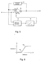
- Figure 5
- illustrates how the chronologically successive histograms are filtered according to a preferred embodiment of the invention,
- Figure 6
- shows two examples of advantageous functional curves of the
adjusting
member 46, and - Figure 7
- is a block diagram of a preferred embodiment of the invention.
- Like numbers for like parts are used in the drawings.
- Figure 3 is a schematical illustration of the operation of a preferred embodiment of the invention. In a system according to the invention, histograms are gathered (10) of the incoming pictures, whereafter the histograms are preprocessed (12) in order to equalize the highest histogram peaks. The preprocessed histograms are chronologically filtered (14), and a mapping function is formed (16) on the basis of each filtered histogram. Finally the pixel values of the incoming signal are mapped (20) by means of a mapping function to form initial values. Prior to the mapping of the pixel values, the incoming signal is delayed (18) for the same duration as there is created delay in the histogram processing steps (10 - 16). The steps represented in Figure 3 are described in more detail below.
- In
step 10 of Figure 3, histograms are gathered of the incoming signal. The gathering of histograms can be carried out in many different ways: - from the whole picture area or only part thereof;
- one or several histograms can be gathered from each picture;
- from part of the pictures, histograms can be left ungathered, in which case histograms are gathered in order to reduce the required calculation power for instance from every third picture;
- in the gathering of histograms, it is possible to observe all pixels in the picture area in question, or only part thereof.
- Because the object under observation may be relatively small in comparison with the whole picture area, the visibility of the object may deteriorate in the histogram equalization, if the equalization is carried out on the basis of the whole picture area. Possible subtitles as well as the black bars used in connection with cinemascope films disturb the equalization. If the histogram is gathered from a sampling window located in the middle region of the picture, said window being of the same size as the picture or somewhat smaller, it is possible to emphasize that part of the picture where the important information is most probably located, i.e. the middle region. By leaving the picture edges unobserved when gathering the histogram, the disturbing effect of subtitles and bars is also avoided.
- In order to speed up the system, in the calculation of the histogram, part of the pixels in the sampling window can be left out of the calculation. For instance sufficient accuracy is of the order every fifth pixel both in the vertical and horizontal directions, when the picture under treatment conforms to the CCIR 601 standard. In that case it is advisable to lowpass-filter the picture in order to avoid errors caused by folding.
- If more than one histogram is gathered from at least a given set of pictures, from different areas of said pictures, histograms gathered from a given region in successive pictures are processed and transformed into mapping functions advantageously apart from the histograms gathered from successive pictures in other regions. Now in the mapping step of the pixel values there can be used more than one mapping function corresponding to a given region in the picture. In an embodiment like this, the mapping function used in the mapping step of the pixel value of each pixel can be chosen or interpolated on the basis of the location of the pixel.
- In
step 12 of Figure 3, the histograms are preprocessed in order to cut off the highest peaks of the histograms. In a preferred embodiment of the invention, the histogram values surpassing the maximum amplification limit are expanded only to the classes surrounding the surpassing class, in which case the effect of equalization is not altered with brightness values that remarkably differ from the general value corresponding to the histogram peak. For example a triangular distribution concentrated around a peak renders a better result than the even distribution according to the prior art. - In a preferred embodiment of the invention, the maximum amplification limit is advantageously determined according to the histogram class, so that in the vicinity of the extreme ends of the histogram, the maximum amplification limit is lower than in the middle regions of the histogram. When following this procedure, a weaker amplification is obtained for the extreme end values than for the medium-bright values. Thus it is possible to avoid an excessive increase of total luminance obtained in almost black pictures, and respectively an excessive decrease of total luminance obtained in almost white pictures. An expansion of the distribution of very dark or very light values would also make the noise more visible than with medium-bright values.
- The histogram equalization result can be further improved by applying a class-dependent value redistribution method, i.e. for instance by weighting said triangular distribution in different ways on different sides of the class to be distributed. For example, near the extreme ends of the brightness value distribution, it is not advisable to redistribute the cut-off peak values back to the area remaining in between the peak and the extreme end, because this would lead to an excessive intensification of the tone differences of the extreme ends and thus decrease the total contrast. The distribution defining the value redistribution can advantageously be determined individually for each histogram class. Consequently, the redistribution method can be changed according to each class under distribution, for instance in a way illustrated in Figure 4.
- After the first expansion, the values of some classes may still surpass the limit. In a preferred embodiment of the invention, these peaks occurring after the first expansion are cut off and distributed evenly to all classes. In order to speed up the operation, this is carried out only once, so that the equalization of the histogram peaks takes place swiftly. There may still remain some peaks exceeding the maximum amplification limit, but in practice an adequate control is thus obtained for the maximum amplification.
- In
step 14 of Figure 3, chronologically successive histograms are filtered for eliminating the flickering phenomenon, among others. In order to avoid an unnatural distortion of the pictures succeeding the cut-off spots, the filter must preserve the edges. Such structures are for instance many known non-linear filters, such as median filters. These, however, produce a delay, wherefore their use is undesirable. An undelayed and effective filtering is achieved with recursive filters. A recursive filtering alone, however, is a compromise between an effective flickering elimination of fairly unchangeable sequences and a rapid adjusting to the new picture after a cut-off spot. - In a preferred embodiment of the present invention, successive histograms are filtered by an adaptive filter, which detects remarkable sudden changes in the picture brightness and adapts itself rapidly to them, but allows only slow changes in the mapping function when remarkable changes do not occur in the brightness of the incoming picture. When using a filter of this type, the pixel value distribution is not remarkably distorted at the cut-off spot of the picture sequence, and disturbing flickering does not occur during slowly changing picture sequences.
- An example of a filter of this type is represented in Figure 5. In its basic structure, the filter is a recursive filter provided with additional parameter-adjusting
members difference calculation member 44 forms a code number describing the difference between the previous filtered histogram and the new histogram. By means of the code number obtained from the calculatingmember 44 and describing the difference of said histograms, the adjustingmember 46 forms a filter adjusting value, whereby the adjustingmember 46 controls the operation of theweighting members - Even a slight, undetectable change in the picture may cause remarkable changes in the original histogram, wherefore it is difficult to calculate the detectable difference on the basis of the original histograms. Because the difference code number is formed on the basis of preprocessed histograms, the highest peaks whereof are expanded in the manner described above, the measures of difference used in the
calculation member 44 can be simple models, such as the sum of the absolute differences per class:where bins is the number of classes, hi is the value of the class i of said preceding filtered histogram and ki is the value of the class i of said new histogram. In the method according to the invention, the difference-describing number code can be calculated in many other known ways, too.
- A few advantageous examples of the possible operation curve of the adjusting
member 46 are illustrated in Figure 6. In the variable, the difference-describing code number produced by thecalculation member 44 is seen on the horizontal axis, and the output value of the adjustingmember 46, i.e. the value of the filter control parameter A, is seen on the vertical axis. - By means of the functional curve of the adjusting
member 46, it is possible to achieve a desired reaction of the filter to the spots of change in the picture sequence. Advantageously the filter filters slight changes in the histogram, so that with low output values of the calculating member, the output value of the adjusting member is near to zero, and the filter filters fairly intensively. If the preceding histogram and the one under observation differ remarkably, the spot in question is probably a cut-off spot of a picture sequence, in which case it is not advantageous that the histograms calculated from the preceding pictures affect the pictures succeeding the cut-off spot. Now the output value of the adjusting member is advantageously near to one, in which case the filter passes the histogram under observation through without remarkable changes. In between these extreme values, there can advantageously be used for instance functional curves represented in Figure 6. As examples of advantageous functional curves of the adjustingmember 46, Figure 6 represents a ramp-type function 100 and a sigmoid-type function 102. - Here the fluctuation range of the different parameters from zero to one is only an example that does by no means restrict the different embodiments of the invention; in this example, the value zero describes the bottom limit of the fluctuation range, and one describes the top limit thereof. In the above specification, the calculating
member 44 and the adjustingmember 46 are described as separate functional blocks only for the sake of clarity of the description. These members can also be combined to form a uniform member producing a corresponding result. - In
step 16 of Figure 3, the preprocessed and filtered histograms are transformed into mapping functions. A mapping function can be defined either for all possible values of the pixel value distribution, or for only certain values, in which case the missing values can be interpolated in connection with the mapping of the pixel values. - Figure 7 illustrates a preferred embodiment of the invention which makes use of the fact that the mapping function and the histogram contain the same information, i.e. on the basis of a histogram, there can always be formed a mapping function, which equalizes the histogram, and vice versa: on the basis of the mapping function, there can always be formed a histogram, which is equalized by said mapping function. In the embodiment of Figure 7, instead of filtering successive histograms (
step 14 in Figure 3), there are filtered (22) mapping functions formed of histograms. The filtering of mapping functions can be realized in similar fashion as the filtering of a histogram, by using for instance the method described above, in connection with Figure 6, for filtering chronologically successive histograms. - The method according to the invention can also be applied for treating color information. Also the values of the color components of the vision signal can be altered by means of the mapping function.
- The above described method to redistribute the values cut off the histogram, by weighting on the triangular distribution in the vicinity of the cut-off peak, is only one example of possible redistribution methods. In said method step, there can also be applied other types of redistribution that differ from an even distribution.
- In connection with the examples describing the different embodiments of the present application, histograms with 256 classes are used by way of example. It is also possible to use, in the various embodiments of the invention, other types of histograms where the class division is defined in a different way than in the examples of the present application.
- The system according to the invention can be realized in many different ways, for example by means of a custom-designed application specific integrated circuit (ASIC) or in a programmed fashion, as a control program of a digital signal processor.
- The cutting off of the histogram peaks according to the method, as well as the redistribution of the cut-off values, are both carried out rapidly, because the number of the iteration cycles is constant and advantageously small, so that the calculation process does not become too cumbersome for a real-time application.
- Owing to an adaptive filtering of successive histograms or mapping functions, the adaptation to the new picture succeeding the cut-off spots in the programme takes place rapidly, whereas in the processing of practically unchanged pictures there is used a slowly changing histogram or a corresponding mapping function, and disturbing flickering is thus avoided.
- In the specification above, the invention is described with reference to a few preferred embodiments only, but it is obvious that the invention can be modified in many ways within the scope of the appended claims.
Claims (7)
- A method for improving contrast in picture sequences, in which methodwhereina picture of a picture sequence is gathered into a histogram,the gathered histogram is processed in order to provide basis for altering the picture contrast,the gathered histogram is filtered on the basis of histograms gathered from chronologically successive pictures in the picture sequence,on the basis of the processed and filtered histogram there is formed a mapping function, andon the basis of the mapping function pixel values of the picture are altered;characterized in thatin each histogram bin where the number of pixel entries in the bin exceeds a predetermined limit, the number of pixel entries in the bin is limited to said predetermined limit, andpixel entries that need to be removed from a bin in order to limit the number of pixel entries in the bin are redistributed in the histogram according to a certain distribution,said distribution emphasizes redistributing the pixel entries that need to be removed into bins lying near to the bin from which they were removed, andan adaptive edge-preserving filter structure is used to filter the gathered histogram on the basis of histograms gathered from chronologically successive pictures in the picture sequence.
- A method for improving contrast in picture sequences, in which methodwhereina picture of a picture sequence is gathered into a histogram,the gathered histogram is transformed in order to provide basis for altering the picture contrast,on the basis of the transformed histogram there is formed a mapping function;characterized in thatin each histogram bin where the number of pixel entries in the bin exceeds a predetermined limit, the number of pixel entries in the bin is limited to said predetermined limit, andpixel entries that need to be removed from a bin in order to limit the number of pixel entries in the bin are redistributed in the histogram according to a certain distribution,said distribution emphasizes redistributing the pixel entries that need to be removed into bins lying near to the bin from which they were removed,an adaptive edge-preserving filter structure is used to filter the formed mapping function on the basis of mapping functions formed on the basis of histograms gathered from chronologically successive pictures in the picture sequence, andby means of the filtered mapping function pixel values of the picture are altered.
- A method according to claim 1 or 2, characterized in that said distribution that emphasizes redistributing the pixel entries that need to be removed into bins lying near to the bin from which they were removed is a triangular distribution.
- A method according to claim 1 or 2, characterized in that the distribution used in the redistribution of the pixel entries that need to be removed from a given bin depends on said bin.
- A method according to claim 4, characterized in thatat the low-value end of the histogram, the distribution emphasizes redistributing the pixel entries that need to be removed into bins with higher values than said bin,at the high-value end of the histogram, the distribution emphasizes redistributing the pixel entries that need to be removed into bins with lower values than said bin, andin the middle region of the histogram, the distribution emphasizes redistributing the pixel entries that need to be removed into bins that are essentially equally on both sides of said bin.
- A method according to claim 1 or 2, characterized in that the method also comprises a step where after the first value removing and redistribution, from each bin where the number of pixel entries surpasses a given, predetermined limit, there are removed the pixel entries surpassing said limit, and the pixel entries that need to be removed are redistributed back to the histogram according to an essentially even distribution.
- A method according to claim 1 or 2, characterized in that said given, predetermined limit depends on the bin of the histogram under observation.
Applications Claiming Priority (2)
| Application Number | Priority Date | Filing Date | Title |
|---|---|---|---|
| FI970388 | 1997-01-30 | ||
| FI970388A FI104521B (en) | 1997-01-30 | 1997-01-30 | Procedure for improving contrast in image sequences |
Publications (3)
| Publication Number | Publication Date |
|---|---|
| EP0856813A2 EP0856813A2 (en) | 1998-08-05 |
| EP0856813A3 EP0856813A3 (en) | 1998-12-09 |
| EP0856813B1 true EP0856813B1 (en) | 2002-08-07 |
Family
ID=8547928
Family Applications (1)
| Application Number | Title | Priority Date | Filing Date |
|---|---|---|---|
| EP98101222A Expired - Lifetime EP0856813B1 (en) | 1997-01-30 | 1998-01-24 | Method for improving contrast in picture sequences |
Country Status (4)
| Country | Link |
|---|---|
| US (1) | US6148103A (en) |
| EP (1) | EP0856813B1 (en) |
| DE (1) | DE69806981T2 (en) |
| FI (1) | FI104521B (en) |
Families Citing this family (55)
| Publication number | Priority date | Publication date | Assignee | Title |
|---|---|---|---|---|
| JP3237582B2 (en) * | 1997-08-28 | 2001-12-10 | 富士ゼロックス株式会社 | Image processing apparatus and image processing method |
| US6421097B1 (en) * | 1998-07-31 | 2002-07-16 | Intel Corporation | Method and apparatus for reducing flicker in a video image sequence |
| US6392764B1 (en) * | 1998-11-12 | 2002-05-21 | Xerox Corporation | Systems and methods for adaptively filtering palettized images |
| FR2793375A1 (en) * | 1999-05-06 | 2000-11-10 | Thomson Multimedia Sa | METHOD FOR DETECTING BLACK BANDS IN A VIDEO IMAGE |
| EP1075140A1 (en) * | 1999-08-02 | 2001-02-07 | Koninklijke Philips Electronics N.V. | Video signal enhancement |
| US6650774B1 (en) * | 1999-10-01 | 2003-11-18 | Microsoft Corporation | Locally adapted histogram equalization |
| US20020135683A1 (en) * | 1999-12-20 | 2002-09-26 | Hideo Tamama | Digital still camera system and method |
| GB2357649A (en) | 1999-12-22 | 2001-06-27 | Nokia Mobile Phones Ltd | Image enhancement using inverse histogram based pixel mapping |
| US6850642B1 (en) * | 2000-01-31 | 2005-02-01 | Micron Technology, Inc. | Dynamic histogram equalization for high dynamic range images |
| EP1134698A1 (en) * | 2000-03-13 | 2001-09-19 | Koninklijke Philips Electronics N.V. | Video-apparatus with histogram modification means |
| EP1164784A1 (en) * | 2000-06-13 | 2001-12-19 | Koninklijke Philips Electronics N.V. | Preventing doming phenomena |
| EP1360833A1 (en) | 2000-08-31 | 2003-11-12 | Rytec Corporation | Sensor and imaging system |
| US7003153B1 (en) * | 2000-09-29 | 2006-02-21 | Sharp Laboratories Of America, Inc. | Video contrast enhancement through partial histogram equalization |
| US7010163B1 (en) * | 2001-04-20 | 2006-03-07 | Shell & Slate Software | Method and apparatus for processing image data |
| FI113132B (en) * | 2001-06-28 | 2004-02-27 | Nokia Corp | Method and apparatus for improving an image |
| US6826310B2 (en) | 2001-07-06 | 2004-11-30 | Jasc Software, Inc. | Automatic contrast enhancement |
| EP1345172A1 (en) * | 2002-02-26 | 2003-09-17 | Sony International (Europe) GmbH | Contrast enhancement for digital images |
| US6937775B2 (en) * | 2002-05-15 | 2005-08-30 | Eastman Kodak Company | Method of enhancing the tone scale of a digital image to extend the linear response range without amplifying noise |
| WO2004023787A2 (en) | 2002-09-06 | 2004-03-18 | Rytec Corporation | Signal intensity range transformation apparatus and method |
| US7174049B2 (en) * | 2002-12-11 | 2007-02-06 | Seiko Epson Corporation | Image upscaling by joint optimization of low and mid-level image variables |
| SG118191A1 (en) | 2003-06-27 | 2006-01-27 | St Microelectronics Asia | Method and system for contrast enhancement of digital video |
| KR100512976B1 (en) * | 2003-08-09 | 2005-09-07 | 삼성전자주식회사 | Black/White streching system capable of improving contrast and a method of Black/White streching thereof |
| US20050057485A1 (en) * | 2003-09-15 | 2005-03-17 | Diefenbaugh Paul S. | Image color transformation to compensate for register saturation |
| TWI283396B (en) * | 2004-03-23 | 2007-07-01 | Lite On Technology Corp | Method for adjusting image contrast |
| FI20045201L (en) | 2004-05-31 | 2005-12-01 | Nokia Corp | Method and system for viewing and enhancing images |
| US7936919B2 (en) * | 2005-01-18 | 2011-05-03 | Fujifilm Corporation | Correction of color balance of face images depending upon whether image is color or monochrome |
| JP4533330B2 (en) * | 2005-04-12 | 2010-09-01 | キヤノン株式会社 | Image forming apparatus and image forming method |
| CA2610262A1 (en) * | 2005-06-07 | 2006-12-14 | Thomson Licensing | Content-based gaussian noise reduction for still image, video and film |
| US7796153B1 (en) * | 2005-07-08 | 2010-09-14 | Itt Manufacturing Enterprises, Inc. | Equalization system and method for an imaging sensor |
| JP4551836B2 (en) * | 2005-07-29 | 2010-09-29 | 株式会社東芝 | Video signal processing apparatus and video signal processing method |
| US7512269B2 (en) * | 2005-08-04 | 2009-03-31 | Asaf Golan | Method of adaptive image contrast enhancement |
| JP4504284B2 (en) * | 2005-08-30 | 2010-07-14 | 株式会社東芝 | Video signal processing apparatus and video signal processing method |
| CN100407765C (en) * | 2005-09-07 | 2008-07-30 | 逐点半导体(上海)有限公司 | Image contrast enhancement device and enhancement method |
| TWI318534B (en) * | 2006-03-23 | 2009-12-11 | Novatek Microelectronics Corp | Method for processing brightness of an image and related device |
| EP1840831A1 (en) * | 2006-03-31 | 2007-10-03 | Sony Deutschland Gmbh | Adaptive histogram equalization for images with strong local contrast |
| SG139602A1 (en) * | 2006-08-08 | 2008-02-29 | St Microelectronics Asia | Automatic contrast enhancement |
| US8009907B1 (en) | 2006-11-08 | 2011-08-30 | Marvell International Ltd. | Localized, adaptive video contrast enhancement using controlled histogram equalization |
| US8260077B2 (en) * | 2006-11-29 | 2012-09-04 | Mstar Semiconductor, Inc. | Method and apparatus for eliminating image blur |
| JP4850689B2 (en) * | 2006-12-22 | 2012-01-11 | キヤノン株式会社 | Image processing apparatus, image processing method, image processing program, and storage medium |
| JP4861845B2 (en) * | 2007-02-05 | 2012-01-25 | 富士通株式会社 | Telop character extraction program, recording medium, method and apparatus |
| US8108211B2 (en) * | 2007-03-29 | 2012-01-31 | Sony Corporation | Method of and apparatus for analyzing noise in a signal processing system |
| US8711249B2 (en) * | 2007-03-29 | 2014-04-29 | Sony Corporation | Method of and apparatus for image denoising |
| TWI376661B (en) * | 2007-03-30 | 2012-11-11 | Novatek Microelectronics Corp | Contrast control apparatus and contrast control method and image display |
| US8144985B2 (en) * | 2007-12-21 | 2012-03-27 | Sony Corporation | Method of high dynamic range compression with detail preservation and noise constraints |
| JP5180916B2 (en) * | 2008-06-25 | 2013-04-10 | 株式会社半導体エネルギー研究所 | Image processing system and image processing method |
| US8781248B2 (en) * | 2010-01-28 | 2014-07-15 | Stmicroelectronics Asia Pacific Pte. Ltd. | Image details preservation and enhancement |
| TR201001660A2 (en) | 2010-03-04 | 2011-09-21 | Vestel Elektron�K Sanay� Ve T�Caret A.�. | Black and white drawing method for dynamic range expansion. |
| US8698961B2 (en) * | 2010-05-21 | 2014-04-15 | Vixs Systems, Inc. | Enhanced histogram equalization |
| US8599318B2 (en) * | 2010-05-21 | 2013-12-03 | Vixs Systems, Inc. | Contrast control device and method therefor |
| JP5627041B2 (en) * | 2010-10-15 | 2014-11-19 | シャープ株式会社 | Image processing apparatus, image processing method, image processing program, and recording medium |
| US20120128244A1 (en) * | 2010-11-19 | 2012-05-24 | Raka Singh | Divide-and-conquer filter for low-light noise reduction |
| US8755625B2 (en) | 2010-11-19 | 2014-06-17 | Analog Devices, Inc. | Component filtering for low-light noise reduction |
| US9041864B2 (en) * | 2012-11-19 | 2015-05-26 | Nokia Technologies Oy | Method and apparatus for temporal stabilization of streaming frames |
| KR102051538B1 (en) * | 2013-09-13 | 2020-01-08 | 에스케이하이닉스 주식회사 | Signal processing device and operating method thereof |
| CN111445394B (en) * | 2019-12-10 | 2023-06-20 | 西南技术物理研究所 | Visible light image self-adaptive enhancement method for air-to-ground observation |
Family Cites Families (10)
| Publication number | Priority date | Publication date | Assignee | Title |
|---|---|---|---|---|
| EP0358459B1 (en) * | 1988-09-08 | 1996-06-19 | Sony Corporation | Picture processing apparatus |
| JPH0787587B2 (en) * | 1990-02-16 | 1995-09-20 | 松下電器産業株式会社 | Gradation correction device |
| US5544258A (en) * | 1991-03-14 | 1996-08-06 | Levien; Raphael L. | Automatic tone correction of images using non-linear histogram processing |
| US5162902A (en) * | 1991-12-16 | 1992-11-10 | Thomson Consumer Electronics, Inc. | Non-linear luminance signal processor responsive to average picture level (APL) of displayed image |
| US5410418A (en) * | 1992-06-24 | 1995-04-25 | Dainippon Screen Mfg. Co., Ltd. | Apparatus for converting image signal representing image having gradation |
| US5450502A (en) * | 1993-10-07 | 1995-09-12 | Xerox Corporation | Image-dependent luminance enhancement |
| BE1007608A3 (en) * | 1993-10-08 | 1995-08-22 | Philips Electronics Nv | Improving picture signal circuit. |
| US5727080A (en) * | 1995-05-03 | 1998-03-10 | Nec Research Institute, Inc. | Dynamic histogram warping of image histograms for constant image brightness, histogram matching and histogram specification |
| JP3501252B2 (en) * | 1995-06-16 | 2004-03-02 | 三菱電機株式会社 | Gradation correction device |
| KR100207426B1 (en) * | 1996-05-08 | 1999-07-15 | 전주범 | Texture classifier using pattern size and orientation |
-
1997
- 1997-01-30 FI FI970388A patent/FI104521B/en active
-
1998
- 1998-01-24 DE DE69806981T patent/DE69806981T2/en not_active Expired - Lifetime
- 1998-01-24 EP EP98101222A patent/EP0856813B1/en not_active Expired - Lifetime
- 1998-01-28 US US09/014,954 patent/US6148103A/en not_active Expired - Lifetime
Also Published As
| Publication number | Publication date |
|---|---|
| EP0856813A2 (en) | 1998-08-05 |
| FI970388A7 (en) | 1998-07-31 |
| EP0856813A3 (en) | 1998-12-09 |
| FI104521B (en) | 2000-02-15 |
| DE69806981D1 (en) | 2002-09-12 |
| FI970388A0 (en) | 1997-01-30 |
| US6148103A (en) | 2000-11-14 |
| DE69806981T2 (en) | 2003-05-08 |
Similar Documents
| Publication | Publication Date | Title |
|---|---|---|
| US6148103A (en) | Method for improving contrast in picture sequences | |
| DE3629409C2 (en) | Method and device for contrast evaluation in electronic image processing | |
| US7424148B2 (en) | Method and system for contrast enhancement of digital video | |
| DE69836540T2 (en) | METHOD AND DEVICE FOR CARRYING OUT IMAGE IMPROVEMENTS | |
| KR100782845B1 (en) | A digital image enhancement method and system using non-log domain illumination correction | |
| EP1887517B1 (en) | Automatic contrast enhancement | |
| JP5337818B2 (en) | Image processing method and apparatus | |
| US7020332B2 (en) | Method and apparatus for enhancing a digital image by applying an inverse histogram-based pixel mapping function to pixels of the digital image | |
| US7349574B1 (en) | System and method for processing non-linear image data from a digital imager | |
| US8009907B1 (en) | Localized, adaptive video contrast enhancement using controlled histogram equalization | |
| JP3465226B2 (en) | Image density conversion processing method | |
| US6915023B2 (en) | Contour correction device | |
| KR20070075872A (en) | Image Processing Method and System Using Gain-Adjustable Cutting Frequency Function Smoothing | |
| KR100512976B1 (en) | Black/White streching system capable of improving contrast and a method of Black/White streching thereof | |
| CN100342718C (en) | Image signal processor | |
| JP3267200B2 (en) | Image processing device | |
| JP2790604B2 (en) | Image processing device | |
| US5448304A (en) | Process for reducing the noise of a video signal | |
| KR100265008B1 (en) | Apparatus for dynamic contrast building up and method thereof | |
| JPH1132201A (en) | Image processing device | |
| KR100813620B1 (en) | Contrast correction device and correction method | |
| Srinivasan et al. | 44.2: Distinguished Paper: Adaptive Contrast Enhancement for Digital Video | |
| EP0666688A1 (en) | Circuit arrangement to accentuate the sharpness and attenuate the noise of a television image | |
| EP0683605A2 (en) | Method and device for enhancing the transients of a video signal in component form | |
| Loomans | Selective Local Content Analysis for Picture Quality Enhancements in Mainstream Television |
Legal Events
| Date | Code | Title | Description |
|---|---|---|---|
| PUAI | Public reference made under article 153(3) epc to a published international application that has entered the european phase |
Free format text: ORIGINAL CODE: 0009012 |
|
| AK | Designated contracting states |
Kind code of ref document: A2 Designated state(s): DE FR GB IT |
|
| AX | Request for extension of the european patent |
Free format text: AL;LT;LV;MK;RO;SI |
|
| PUAL | Search report despatched |
Free format text: ORIGINAL CODE: 0009013 |
|
| AK | Designated contracting states |
Kind code of ref document: A3 Designated state(s): AT BE CH DE DK ES FI FR GB GR IE IT LI LU MC NL PT SE |
|
| AX | Request for extension of the european patent |
Free format text: AL;LT;LV;MK;RO;SI |
|
| 17P | Request for examination filed |
Effective date: 19981110 |
|
| AKX | Designation fees paid |
Free format text: DE FR GB IT |
|
| 17Q | First examination report despatched |
Effective date: 20010417 |
|
| GRAG | Despatch of communication of intention to grant |
Free format text: ORIGINAL CODE: EPIDOS AGRA |
|
| GRAG | Despatch of communication of intention to grant |
Free format text: ORIGINAL CODE: EPIDOS AGRA |
|
| GRAH | Despatch of communication of intention to grant a patent |
Free format text: ORIGINAL CODE: EPIDOS IGRA |
|
| RAP1 | Party data changed (applicant data changed or rights of an application transferred) |
Owner name: NOKIA TECHNOLOGY GMBH |
|
| GRAH | Despatch of communication of intention to grant a patent |
Free format text: ORIGINAL CODE: EPIDOS IGRA |
|
| RAP1 | Party data changed (applicant data changed or rights of an application transferred) |
Owner name: NOKIA TECHNOLOGY GMBH |
|
| GRAA | (expected) grant |
Free format text: ORIGINAL CODE: 0009210 |
|
| AK | Designated contracting states |
Kind code of ref document: B1 Designated state(s): DE FR GB IT |
|
| REG | Reference to a national code |
Ref country code: GB Ref legal event code: FG4D |
|
| REF | Corresponds to: |
Ref document number: 69806981 Country of ref document: DE Date of ref document: 20020912 |
|
| ET | Fr: translation filed | ||
| PLBE | No opposition filed within time limit |
Free format text: ORIGINAL CODE: 0009261 |
|
| STAA | Information on the status of an ep patent application or granted ep patent |
Free format text: STATUS: NO OPPOSITION FILED WITHIN TIME LIMIT |
|
| 26N | No opposition filed |
Effective date: 20030508 |
|
| PGFP | Annual fee paid to national office [announced via postgrant information from national office to epo] |
Ref country code: FR Payment date: 20110128 Year of fee payment: 14 Ref country code: IT Payment date: 20110122 Year of fee payment: 14 |
|
| REG | Reference to a national code |
Ref country code: FR Ref legal event code: ST Effective date: 20120928 |
|
| PG25 | Lapsed in a contracting state [announced via postgrant information from national office to epo] |
Ref country code: IT Free format text: LAPSE BECAUSE OF NON-PAYMENT OF DUE FEES Effective date: 20120124 |
|
| REG | Reference to a national code |
Ref country code: DE Ref legal event code: R082 Ref document number: 69806981 Country of ref document: DE Representative=s name: BECKER, KURIG, STRAUS, DE |
|
| PG25 | Lapsed in a contracting state [announced via postgrant information from national office to epo] |
Ref country code: FR Free format text: LAPSE BECAUSE OF NON-PAYMENT OF DUE FEES Effective date: 20120131 |
|
| REG | Reference to a national code |
Ref country code: FR Ref legal event code: TP Owner name: NOKIA CORPORATION, FI Effective date: 20121212 |
|
| REG | Reference to a national code |
Ref country code: GB Ref legal event code: 732E Free format text: REGISTERED BETWEEN 20121220 AND 20121221 |
|
| REG | Reference to a national code |
Ref country code: DE Ref legal event code: R082 Ref document number: 69806981 Country of ref document: DE Representative=s name: BECKER, KURIG, STRAUS, DE Effective date: 20121207 Ref country code: DE Ref legal event code: R081 Ref document number: 69806981 Country of ref document: DE Owner name: NOKIA TECHNOLOGIES OY, FI Free format text: FORMER OWNER: NOKIA TECHNOLOGY GMBH, 44807 BOCHUM, DE Effective date: 20121207 Ref country code: DE Ref legal event code: R081 Ref document number: 69806981 Country of ref document: DE Owner name: NOKIA CORPORATION, DE Free format text: FORMER OWNER: NOKIA TECHNOLOGY GMBH, 44807 BOCHUM, DE Effective date: 20121207 |
|
| REG | Reference to a national code |
Ref country code: GB Ref legal event code: 732E Free format text: REGISTERED BETWEEN 20150910 AND 20150916 |
|
| REG | Reference to a national code |
Ref country code: DE Ref legal event code: R082 Ref document number: 69806981 Country of ref document: DE Representative=s name: BECKER, KURIG, STRAUS, DE Ref country code: DE Ref legal event code: R081 Ref document number: 69806981 Country of ref document: DE Owner name: NOKIA TECHNOLOGIES OY, FI Free format text: FORMER OWNER: NOKIA CORPORATION, 44807 BOCHUM, DE |
|
| PGFP | Annual fee paid to national office [announced via postgrant information from national office to epo] |
Ref country code: DE Payment date: 20170117 Year of fee payment: 20 |
|
| PGFP | Annual fee paid to national office [announced via postgrant information from national office to epo] |
Ref country code: GB Payment date: 20170118 Year of fee payment: 20 |
|
| REG | Reference to a national code |
Ref country code: DE Ref legal event code: R071 Ref document number: 69806981 Country of ref document: DE |
|
| REG | Reference to a national code |
Ref country code: GB Ref legal event code: PE20 Expiry date: 20180123 |
|
| PG25 | Lapsed in a contracting state [announced via postgrant information from national office to epo] |
Ref country code: GB Free format text: LAPSE BECAUSE OF EXPIRATION OF PROTECTION Effective date: 20180123 |