EP0856283B1 - Ultrasonic diagnostic apparatus having a patient-use monitor - Google Patents
Ultrasonic diagnostic apparatus having a patient-use monitor Download PDFInfo
- Publication number
- EP0856283B1 EP0856283B1 EP19980101600 EP98101600A EP0856283B1 EP 0856283 B1 EP0856283 B1 EP 0856283B1 EP 19980101600 EP19980101600 EP 19980101600 EP 98101600 A EP98101600 A EP 98101600A EP 0856283 B1 EP0856283 B1 EP 0856283B1
- Authority
- EP
- European Patent Office
- Prior art keywords
- ultrasonic diagnostic
- patient
- diagnostic apparatus
- monitor
- main body
- Prior art date
- Legal status (The legal status is an assumption and is not a legal conclusion. Google has not performed a legal analysis and makes no representation as to the accuracy of the status listed.)
- Expired - Lifetime
Links
Images

Classifications
-
- G—PHYSICS
- G01—MEASURING; TESTING
- G01S—RADIO DIRECTION-FINDING; RADIO NAVIGATION; DETERMINING DISTANCE OR VELOCITY BY USE OF RADIO WAVES; LOCATING OR PRESENCE-DETECTING BY USE OF THE REFLECTION OR RERADIATION OF RADIO WAVES; ANALOGOUS ARRANGEMENTS USING OTHER WAVES
- G01S7/00—Details of systems according to groups G01S13/00, G01S15/00, G01S17/00
- G01S7/52—Details of systems according to groups G01S13/00, G01S15/00, G01S17/00 of systems according to group G01S15/00
- G01S7/52017—Details of systems according to groups G01S13/00, G01S15/00, G01S17/00 of systems according to group G01S15/00 particularly adapted to short-range imaging
- G01S7/52053—Display arrangements
-
- A—HUMAN NECESSITIES
- A61—MEDICAL OR VETERINARY SCIENCE; HYGIENE
- A61B—DIAGNOSIS; SURGERY; IDENTIFICATION
- A61B8/00—Diagnosis using ultrasonic, sonic or infrasonic waves
-
- A—HUMAN NECESSITIES
- A61—MEDICAL OR VETERINARY SCIENCE; HYGIENE
- A61B—DIAGNOSIS; SURGERY; IDENTIFICATION
- A61B8/00—Diagnosis using ultrasonic, sonic or infrasonic waves
- A61B8/46—Ultrasonic, sonic or infrasonic diagnostic devices with special arrangements for interfacing with the operator or the patient
- A61B8/461—Displaying means of special interest
- A61B8/462—Displaying means of special interest characterised by constructional features of the display
-
- A—HUMAN NECESSITIES
- A61—MEDICAL OR VETERINARY SCIENCE; HYGIENE
- A61B—DIAGNOSIS; SURGERY; IDENTIFICATION
- A61B8/00—Diagnosis using ultrasonic, sonic or infrasonic waves
- A61B8/46—Ultrasonic, sonic or infrasonic diagnostic devices with special arrangements for interfacing with the operator or the patient
- A61B8/461—Displaying means of special interest
- A61B8/464—Displaying means of special interest involving a plurality of displays
-
- A—HUMAN NECESSITIES
- A61—MEDICAL OR VETERINARY SCIENCE; HYGIENE
- A61B—DIAGNOSIS; SURGERY; IDENTIFICATION
- A61B8/00—Diagnosis using ultrasonic, sonic or infrasonic waves
- A61B8/46—Ultrasonic, sonic or infrasonic diagnostic devices with special arrangements for interfacing with the operator or the patient
- A61B8/467—Ultrasonic, sonic or infrasonic diagnostic devices with special arrangements for interfacing with the operator or the patient characterised by special input means
-
- G—PHYSICS
- G01—MEASURING; TESTING
- G01S—RADIO DIRECTION-FINDING; RADIO NAVIGATION; DETERMINING DISTANCE OR VELOCITY BY USE OF RADIO WAVES; LOCATING OR PRESENCE-DETECTING BY USE OF THE REFLECTION OR RERADIATION OF RADIO WAVES; ANALOGOUS ARRANGEMENTS USING OTHER WAVES
- G01S15/00—Systems using the reflection or reradiation of acoustic waves, e.g. sonar systems
- G01S15/88—Sonar systems specially adapted for specific applications
- G01S15/89—Sonar systems specially adapted for specific applications for mapping or imaging
- G01S15/8906—Short-range imaging systems; Acoustic microscope systems using pulse-echo techniques
- G01S15/899—Combination of imaging systems with ancillary equipment
-
- G—PHYSICS
- G01—MEASURING; TESTING
- G01S—RADIO DIRECTION-FINDING; RADIO NAVIGATION; DETERMINING DISTANCE OR VELOCITY BY USE OF RADIO WAVES; LOCATING OR PRESENCE-DETECTING BY USE OF THE REFLECTION OR RERADIATION OF RADIO WAVES; ANALOGOUS ARRANGEMENTS USING OTHER WAVES
- G01S7/00—Details of systems according to groups G01S13/00, G01S15/00, G01S17/00
- G01S7/52—Details of systems according to groups G01S13/00, G01S15/00, G01S17/00 of systems according to group G01S15/00
- G01S7/52017—Details of systems according to groups G01S13/00, G01S15/00, G01S17/00 of systems according to group G01S15/00 particularly adapted to short-range imaging
- G01S7/52079—Constructional features
- G01S7/52084—Constructional features related to particular user interfaces
-
- A—HUMAN NECESSITIES
- A61—MEDICAL OR VETERINARY SCIENCE; HYGIENE
- A61B—DIAGNOSIS; SURGERY; IDENTIFICATION
- A61B8/00—Diagnosis using ultrasonic, sonic or infrasonic waves
- A61B8/44—Constructional features of the ultrasonic, sonic or infrasonic diagnostic device
- A61B8/4405—Device being mounted on a trolley
Definitions
- the present invention relates to an ultrasonic diagnostic apparatus, and more particularly, to an ultrasonic diagnostic apparatus having a patient-use monitor mounted at the side of a body of the ultrasonic diagnostic apparatus, in order to make a patient see his or her diagnostic results easily.
- an ultrasonic diagnostic apparatus uses an ultrasonic wave to obtain information on the inner state of a human body without having a surgical operation with respect to the patient.
- the ultrasonic diagnostic apparatus emits an ultrasonic wave into a human body, analyzes a reflected wave from the human body, and displays information on the human body on a monitor.
- a monitor for displaying human body information thereon is positioned in front of an operator in order to have the operator facilitate to watch the monitor.
- the patient cannot see his or her diagnostic results during the operator's diagnosis.
- the operator should turn the monitor to the direction of the patient's visibility.
- a subsidiary monitor in the visible area in which the patient can see it in addition to a main monitor for enabling an operator to monitor the human body of the patient.
- a support for supporting a subsidiary monitor is needed to install the subsidiary monitor in addition to a main monitor placed on top of the main body of the ultrasonic diagnostic apparatus.
- a support for supporting a subsidiary monitor requires a more space for supporting a monitor, and movement of the subsidiary monitor inconveniences an operator.
- EP 520,338 relates to an ultrasound imagining system and method for controlling the system having a control panel which includes in menu items divided into system mode the new items for selecting a system mode and control set in menu items for selecting functions corresponding to a selected system mode menu item; the system comprising also a display for displaying the ultrasound image generated by the system.
- USP 5,415,287 relates to an endoscope holding and a storing apparatus which catches and holds an endoscope on an endoscope system storage rack or a system card and which makes transportation of an used endoscope easier.
- the endoscope system comprises a monitor part positioned on a pillar member and has a main monitor which is mounted on the monitor term base; further it comprises a nurse monitor and a patient monitor on the said surface on the upper part of the pillar member.
- the nurse monitor and patient monitor are provided with a hook and can be held by the hook itself located on the upper part of the pillar member.
- an object of the present invention to provide an ultrasonic diagnostic apparatus which is compatible with other types of ultrasonic diagnostic apparatuses, in which a compact subsidiary monitor for a patient's use which is constructed as a liquid crystal panel is detachably installed in any part of the main body.
- an ultrasonic diagnostic apparatus including a main body (10) in which a conversion circuit for converting an ultrasonic echo signal received from a probe into a video signal is installed, and a main monitor (20) for displaying the video signal thereon, the ultrasonic diagnostic apparatus characterized in that it comprises:
- the ultrasonic diagnostic apparatus includes a main body 10 housing therein a circuit for converting an ultrasonic echo signal input from a probe (not shown) into a video signal to be displayed, and a main monitor 20 for displaying the video signal thereon.
- the main monitor 20 is connected to the main body 10, and usually placed in front of an operator in order to enable the operator to monitor the state of a patient.
- the main monitor 20 can be rotated so that the operator can see diagnostic results at various angles of view.
- a key manipulator board 30 needed for diagnosis is located on the top-front of the main body 10.
- a receiving recess 12 for a patient-use monitor 40 is formed at the side of the main body 10. Since the patient is usually located at the side of the ultrasonic diagnostic apparatus, it is preferable that the receiving recess 12 to be connected with/disconnected from the patient-use monitor 40 is formed at the side of the main body 10.
- the patient-use monitor 40 according to the present invention includes a display 42 for displaying an image applied from the main body 10 and a rod-shaped support shaft 44 which is inserted into the receiving recess 12 of the main body 10.
- a compact liquid crystal monitor can be used as the display 42.
- the patient-use monitor 40 includes a video signal input port (not shown) for receiving a video signal applied from the main body 10.
- the main body 10 and the video signal input port are connected to each other via a predetermined video signal transmission cable.
- the patient-use monitor 40 includes a power input port (not shown) via which power is supplied from the main body 10.. Otherwise, power can be supplied to the patient-use monitor 40 via an adapter connector from an external source.
- the display 42 can be rotated around the fixed support shaft 44.
- the ultrasonic diagnostic apparatus is compatible with other types of ultrasonic diagnostic apparatuses including each receiving recess 12 for housing a support shaft 44 of a patient-use monitor 40.
- the video signals applied from other types of the ultrasonic diagnostic apparatuses can be displayed on the patient-use monitor 40.
- the patient-use monitor 40 can use other kinds of monitors as well as the above-described liquid crystal monitor. It is also more preferable that the patient-use monitor 40 can be easily moved and is compact and light.
- the ultrasonic diagnostic apparatus provides an ultrasonic diagnostic apparatus having a patient-use monitor which is detachable from a main body and enables a patient to see the diagnostic results easily. Since the patient-use monitor of the present invention can be connected with and disconnected from the other types of ultrasonic diagnostic apparatuses having each receiving recess formed on the main body, the patient-use monitor can be used by being connected with other types of the ultrasonic diagnostic apparatuses.
Landscapes
- Health & Medical Sciences (AREA)
- Life Sciences & Earth Sciences (AREA)
- Engineering & Computer Science (AREA)
- Physics & Mathematics (AREA)
- Remote Sensing (AREA)
- Radar, Positioning & Navigation (AREA)
- Radiology & Medical Imaging (AREA)
- Public Health (AREA)
- Biomedical Technology (AREA)
- Heart & Thoracic Surgery (AREA)
- Medical Informatics (AREA)
- Molecular Biology (AREA)
- Surgery (AREA)
- Animal Behavior & Ethology (AREA)
- General Health & Medical Sciences (AREA)
- Pathology (AREA)
- Veterinary Medicine (AREA)
- Biophysics (AREA)
- Nuclear Medicine, Radiotherapy & Molecular Imaging (AREA)
- Computer Networks & Wireless Communication (AREA)
- General Physics & Mathematics (AREA)
- Acoustics & Sound (AREA)
- Human Computer Interaction (AREA)
- Ultra Sonic Daignosis Equipment (AREA)
Description
- The present invention relates to an ultrasonic diagnostic apparatus, and more particularly, to an ultrasonic diagnostic apparatus having a patient-use monitor mounted at the side of a body of the ultrasonic diagnostic apparatus, in order to make a patient see his or her diagnostic results easily.
- In general, an ultrasonic diagnostic apparatus uses an ultrasonic wave to obtain information on the inner state of a human body without having a surgical operation with respect to the patient. The ultrasonic diagnostic apparatus emits an ultrasonic wave into a human body, analyzes a reflected wave from the human body, and displays information on the human body on a monitor. A monitor for displaying human body information thereon is positioned in front of an operator in order to have the operator facilitate to watch the monitor. As a result, the patient cannot see his or her diagnostic results during the operator's diagnosis. In the case where the patient wishes to see his or her diagnostic results, the operator should turn the monitor to the direction of the patient's visibility. As an alternative for enabling a patient to see his or her diagnostic results, there is a method for installing a subsidiary monitor in the visible area in which the patient can see it in addition to a main monitor for enabling an operator to monitor the human body of the patient.
- However, a support for supporting a subsidiary monitor is needed to install the subsidiary monitor in addition to a main monitor placed on top of the main body of the ultrasonic diagnostic apparatus. Thus, such a support requires a more space for supporting a monitor, and movement of the subsidiary monitor inconveniences an operator.
- EP 520,338 relates to an ultrasound imagining system and method for controlling the system having a control panel which includes in menu items divided into system mode the new items for selecting a system mode and control set in menu items for selecting functions corresponding to a selected system mode menu item; the system comprising also a display for displaying the ultrasound image generated by the system.
- USP 5,415,287 relates to an endoscope holding and a storing apparatus which catches and holds an endoscope on an endoscope system storage rack or a system card and which makes transportation of an used endoscope easier. The endoscope system comprises a monitor part positioned on a pillar member and has a main monitor which is mounted on the monitor term base; further it comprises a nurse monitor and a patient monitor on the said surface on the upper part of the pillar member. The nurse monitor and patient monitor are provided with a hook and can be held by the hook itself located on the upper part of the pillar member.
- To solve the above problems, it is an object of the present invention to provide an ultrasonic diagnostic apparatus which is compatible with other types of ultrasonic diagnostic apparatuses, in which a compact subsidiary monitor for a patient's use which is constructed as a liquid crystal panel is detachably installed in any part of the main body.
- To accomplish the above object of the present invention, there is provided an ultrasonic diagnostic apparatus including a main body (10) in which a conversion circuit for converting an ultrasonic echo signal received from a probe into a video signal is installed, and a main monitor (20) for displaying the video signal thereon, the ultrasonic diagnostic apparatus characterized in that it comprises:
- a receiving recess (12) formed at the main body (10), for housing a patient-use monitor (40); and
- a patient-use monitor (40) including a support shaft (44) which is adapted to be connected with and disconnected from the receiving recess (12); and a display for displaying a video signal applied from the main body (10).
-
- The preferred embodiment is described with reference to the drawings wherein:
- Fig. 1 is a perspective view of an ultrasonic diagnostic apparatus having a patient-use monitor according to a preferred embodiment of the present invention; and
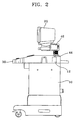
- Fig. 2 is a side view of the apparatus shown in Fig. 1.
-
- A preferred embodiment of the present invention will be described in detail with reference to the accompanying drawings.
- In Figs. 1 and 2 showing an ultrasonic diagnostic apparatus having a patient-use monitor according to a preferred embodiment of the present invention, the ultrasonic diagnostic apparatus includes a
main body 10 housing therein a circuit for converting an ultrasonic echo signal input from a probe (not shown) into a video signal to be displayed, and amain monitor 20 for displaying the video signal thereon. Themain monitor 20 is connected to themain body 10, and usually placed in front of an operator in order to enable the operator to monitor the state of a patient. Themain monitor 20 can be rotated so that the operator can see diagnostic results at various angles of view. Akey manipulator board 30 needed for diagnosis is located on the top-front of themain body 10. Areceiving recess 12 for a patient-use monitor 40 is formed at the side of themain body 10. Since the patient is usually located at the side of the ultrasonic diagnostic apparatus, it is preferable that the receivingrecess 12 to be connected with/disconnected from the patient-use monitor 40 is formed at the side of themain body 10. The patient-use monitor 40 according to the present invention includes adisplay 42 for displaying an image applied from themain body 10 and a rod-shaped support shaft 44 which is inserted into the receivingrecess 12 of themain body 10. - In this embodiment of the present invention, a compact liquid crystal monitor can be used as the
display 42. The patient-use monitor 40 includes a video signal input port (not shown) for receiving a video signal applied from themain body 10. Themain body 10 and the video signal input port are connected to each other via a predetermined video signal transmission cable. Also, the patient-use monitor 40 includes a power input port (not shown) via which power is supplied from themain body 10.. Otherwise, power can be supplied to the patient-use monitor 40 via an adapter connector from an external source. Also, thedisplay 42 can be rotated around thefixed support shaft 44. - The ultrasonic diagnostic apparatus according to the present invention is compatible with other types of ultrasonic diagnostic apparatuses including each receiving
recess 12 for housing asupport shaft 44 of a patient-use monitor 40. Thus, the video signals applied from other types of the ultrasonic diagnostic apparatuses can be displayed on the patient-use monitor 40. Also, the patient-use monitor 40 can use other kinds of monitors as well as the above-described liquid crystal monitor. It is also more preferable that the patient-use monitor 40 can be easily moved and is compact and light. - As described above, the ultrasonic diagnostic apparatus according to the present invention provides an ultrasonic diagnostic apparatus having a patient-use monitor which is detachable from a main body and enables a patient to see the diagnostic results easily. Since the patient-use monitor of the present invention can be connected with and disconnected from the other types of ultrasonic diagnostic apparatuses having each receiving recess formed on the main body, the patient-use monitor can be used by being connected with other types of the ultrasonic diagnostic apparatuses.
- The invention has been described with certain embodiments for illustrative purpose only without limiting the invention.
Claims (8)
- An ultrasonic diagnostic apparatus including a main body (10) in which a conversion circuit for converting an ultrasonic echo signal received from a probe into a video signal is installed, and a main monitor (20) for displaying the video signal thereon, the ultrasonic diagnostic apparatus characterized in that it comprises:a receiving recess (12) formed at the main body (10), for housing a patient-use monitor (40); anda patient-use monitor (40) including a support shaft (44) which is adapted to be connected with and disconnected from the receiving recess (12); and a display for displaying a video signal applied from the main body (10).
- The ultrasonic diagnostic apparatus according to claim 1, wherein said' display in the patient-use monitor is a liquid crystal panel.
- The ultrasonic diagnostic apparatus according to claim 1, wherein said patient-use monitor (40) comprises a power point input port receiving power supplied from the main body (10).
- The ultrasonic diagnostic apparatus according to claim 3, wherein said patent-use monitor (40) further comprises an external power input port to which power can be supplied from an external source.
- The ultrasonic diagnostic apparatus according to claim 1, wherein said patent-use monitor (40) comprises a video signal input port receiving a video signal applied from the main body (10) via a predetermined video signal tansmission cable.
- The ultrasonic diagnostic apparatus according to claim 1, wherein said display can be rotated around the fixed support shaft (44).
- The ultrasonic diagnostic apparatus according to claim 1, wherein said patient-use monitor (40) is compatible with other types of ultrasonic diagnostic apparatuses having each said connector, so that the former can be connected with and disconnected from the latter.
- The ultrasonic diagnostic apparatus according to claim 1, wherein said patient-use monitor (40) is installed at the side of the main body (10).
Applications Claiming Priority (2)
| Application Number | Priority Date | Filing Date | Title |
|---|---|---|---|
| KR1019970003421A KR100197583B1 (en) | 1997-02-04 | 1997-02-04 | Ultrasonic wave diagnosis device having monitor for patients |
| KR973421 | 1997-02-04 |
Publications (2)
| Publication Number | Publication Date |
|---|---|
| EP0856283A1 EP0856283A1 (en) | 1998-08-05 |
| EP0856283B1 true EP0856283B1 (en) | 2003-11-26 |
Family
ID=19496392
Family Applications (1)
| Application Number | Title | Priority Date | Filing Date |
|---|---|---|---|
| EP19980101600 Expired - Lifetime EP0856283B1 (en) | 1997-02-04 | 1998-01-30 | Ultrasonic diagnostic apparatus having a patient-use monitor |
Country Status (5)
| Country | Link |
|---|---|
| US (1) | US5941824A (en) |
| EP (1) | EP0856283B1 (en) |
| JP (1) | JPH10216125A (en) |
| KR (1) | KR100197583B1 (en) |
| DE (1) | DE69819944T2 (en) |
Families Citing this family (24)
| Publication number | Priority date | Publication date | Assignee | Title |
|---|---|---|---|---|
| US6142940A (en) * | 1998-10-06 | 2000-11-07 | Scimed Life Systems, Inc. | Control panel for intravascular ultrasonic imaging system |
| KR200251499Y1 (en) * | 2001-08-07 | 2001-11-22 | 주식회사메디아나 | Apparatus for magnifying and displaying region of the human body |
| US6821250B2 (en) | 2002-05-23 | 2004-11-23 | Koninklijke Philips Electronics N.V. | Diagnostic ultrasound system cart with movable probe holders |
| US6663569B1 (en) * | 2002-05-23 | 2003-12-16 | Koninklijke Philips Electronics N.V. | Diagnostic ultrasound system cart with variable elevation control panel |
| USD512508S1 (en) | 2002-05-23 | 2005-12-06 | Koninklijke Philips Electronics N.V. | Portable medical ultrasonic imaging instrument |
| US6669639B1 (en) | 2002-10-08 | 2003-12-30 | Koninklijke Philips Electronics N.V. | Ultrasonic diagnostic imaging system with articulating display |
| US20050023786A1 (en) * | 2003-08-01 | 2005-02-03 | Rubbermaid Commercial Products Llc | Cart for use with electronic device |
| USD529611S1 (en) * | 2004-08-24 | 2006-10-03 | Kabushiki Kaisha Toshiba | Measuring apparatus for an ultrasonic diagnosis apparatus |
| JP4381340B2 (en) * | 2005-04-11 | 2009-12-09 | ジーイー・メディカル・システムズ・グローバル・テクノロジー・カンパニー・エルエルシー | Ultrasonic diagnostic equipment |
| JP4266382B2 (en) * | 2006-07-18 | 2009-05-20 | アロカ株式会社 | Ultrasonic diagnostic equipment |
| JP2009101073A (en) * | 2007-10-25 | 2009-05-14 | Ge Medical Systems Global Technology Co Llc | Ultrasonic imaging apparatus |
| WO2010076723A1 (en) * | 2008-12-30 | 2010-07-08 | Koninklijke Philips Electronics N.V. | Ultrasound imaging apparatus with patient display |
| JP5085614B2 (en) * | 2009-07-10 | 2012-11-28 | ジーイー・メディカル・システムズ・グローバル・テクノロジー・カンパニー・エルエルシー | Ultrasonic diagnostic equipment |
| JP5437048B2 (en) * | 2009-12-18 | 2014-03-12 | ジーイー・メディカル・システムズ・グローバル・テクノロジー・カンパニー・エルエルシー | Ultrasonic diagnostic equipment |
| CA2783209C (en) | 2009-12-22 | 2017-03-14 | Msd Oss B.V. | Amino-heteroaryl derivatives as hcn blockers |
| USD658766S1 (en) * | 2011-05-18 | 2012-05-01 | Kabushiki Kaisha Toshiba | Portion of an ultrasonic diagnosis device |
| USD662208S1 (en) * | 2011-05-18 | 2012-06-19 | Kabushiki Kaisha Toshiba | Ultrasonic diagnosis device |
| CN105283134A (en) * | 2013-05-31 | 2016-01-27 | 日立阿洛卡医疗株式会社 | Ultrasonic diagnostic device |
| CN104658394A (en) * | 2015-02-13 | 2015-05-27 | 苏州敏行医学信息技术有限公司 | Virtual teaching training system for puncture |
| CN106551706B (en) * | 2015-09-30 | 2020-03-31 | 无锡祥生医疗科技股份有限公司 | Ultrasonic diagnostic apparatus convenient to disassemble and assemble |
| USD788047S1 (en) * | 2015-05-04 | 2017-05-30 | Siemens Aktiengesellschaft | Touch screen for medical apparatus |
| USD940882S1 (en) * | 2020-08-19 | 2022-01-11 | Fujifilm Sonosite, Inc. | Ultrasound device with control panel |
| JP1703783S (en) * | 2021-04-23 | 2022-01-04 | Ultrasound diagnostic machine | |
| US12558802B2 (en) | 2022-12-02 | 2026-02-24 | Ergotron, Inc. | Integrated lock mechanism for an articulating arm |
Family Cites Families (7)
| Publication number | Priority date | Publication date | Assignee | Title |
|---|---|---|---|---|
| US4564018A (en) * | 1982-10-28 | 1986-01-14 | Storz Instrument Company | Ultrasonic system for obtaining ocular measurements |
| US4625731A (en) * | 1984-10-10 | 1986-12-02 | Picker International, Inc. | Ultrasonic image display mounting |
| JP3128224B2 (en) * | 1989-08-30 | 2001-01-29 | 株式会社東芝 | Ultrasound diagnostic equipment |
| US5161535A (en) * | 1991-06-24 | 1992-11-10 | Hewlett-Packard Company | Medical ultrasound imaging system having a partitioned menu |
| US5415287A (en) * | 1992-01-15 | 1995-05-16 | Olympus Optical Co., Ltd. | Endoscope holding and storing apparatus |
| EP0610602B2 (en) * | 1993-02-11 | 2010-11-24 | Agfa HealthCare N.V. | Method of displaying (a) radiographic image(s) |
| US5851186A (en) * | 1996-02-27 | 1998-12-22 | Atl Ultrasound, Inc. | Ultrasonic diagnostic imaging system with universal access to diagnostic information and images |
-
1997
- 1997-02-04 KR KR1019970003421A patent/KR100197583B1/en not_active Expired - Lifetime
-
1998
- 1998-01-30 EP EP19980101600 patent/EP0856283B1/en not_active Expired - Lifetime
- 1998-01-30 DE DE1998619944 patent/DE69819944T2/en not_active Expired - Lifetime
- 1998-01-30 JP JP1958398A patent/JPH10216125A/en active Pending
- 1998-02-03 US US09/018,009 patent/US5941824A/en not_active Expired - Lifetime
Also Published As
| Publication number | Publication date |
|---|---|
| EP0856283A1 (en) | 1998-08-05 |
| JPH10216125A (en) | 1998-08-18 |
| KR19980067410A (en) | 1998-10-15 |
| DE69819944T2 (en) | 2004-12-16 |
| DE69819944D1 (en) | 2004-01-08 |
| KR100197583B1 (en) | 1999-06-15 |
| US5941824A (en) | 1999-08-24 |
Similar Documents
| Publication | Publication Date | Title |
|---|---|---|
| US5941824A (en) | Ultrasonic diagnostic apparatus having a patient-use monitor | |
| EP0918491B1 (en) | Image display system | |
| US6447451B1 (en) | Mobile ultrasound diagnostic instrument and docking stand | |
| EP1981405B1 (en) | Control panel for a medical imaging system | |
| EP0763344B1 (en) | Portable ultrasonic diagnostic apparatus | |
| US4895161A (en) | Transportable data module and display unit for patient monitoring system | |
| US5005559A (en) | Video-graphic arthroscopy system | |
| US4715385A (en) | Patient monitoring system having transportable data module and display unit | |
| US20070238922A1 (en) | Endoscope shape detecting device | |
| GB2345543A (en) | Ultrasonic visualisation system with remote components | |
| US12029613B2 (en) | Diagnostic ultrasound apparatus | |
| US8234922B2 (en) | Ultrasonic diagnostic equipment | |
| JP3279674B2 (en) | Ultrasound diagnostic equipment | |
| JPS62227326A (en) | Ultrasonic diagnostic apparatus | |
| EP1285624A2 (en) | Ophtalmic examination and treatment system | |
| JPH03128052A (en) | Dental therapeutic device | |
| JP3070102U (en) | Ultrasound diagnostic equipment with monitor | |
| JP3483207B2 (en) | Ultrasound diagnostic equipment | |
| JP2828110B2 (en) | Endoscope inspection table | |
| JPH09313489A (en) | Portable ultrasonic diagnostic equipment | |
| US20090227873A1 (en) | Data visualization method for an ultrasound imaging system | |
| JP2005143734A (en) | Ultrasonic diagnostic equipment | |
| JP2961763B2 (en) | Dental treatment equipment | |
| JP2002291738A (en) | Ultrasonograph | |
| JPH10211201A (en) | Ultrasound diagnostic system |
Legal Events
| Date | Code | Title | Description |
|---|---|---|---|
| PUAI | Public reference made under article 153(3) epc to a published international application that has entered the european phase |
Free format text: ORIGINAL CODE: 0009012 |
|
| AK | Designated contracting states |
Kind code of ref document: A1 Designated state(s): DE FR GB IT NL |
|
| AX | Request for extension of the european patent |
Free format text: AL;LT;LV;MK;RO;SI |
|
| 17P | Request for examination filed |
Effective date: 19990108 |
|
| AKX | Designation fees paid |
Free format text: DE FR GB IT NL |
|
| RBV | Designated contracting states (corrected) |
Designated state(s): DE FR GB IT NL |
|
| 17Q | First examination report despatched |
Effective date: 20021008 |
|
| GRAH | Despatch of communication of intention to grant a patent |
Free format text: ORIGINAL CODE: EPIDOS IGRA |
|
| RIC1 | Information provided on ipc code assigned before grant |
Ipc: 7G 01S 7/52 B Ipc: 7A 61B 19/00 B Ipc: 7A 61B 8/00 A |
|
| RIC1 | Information provided on ipc code assigned before grant |
Ipc: 7G 01S 7/52 B Ipc: 7A 61B 19/00 B Ipc: 7A 61B 8/00 A |
|
| GRAS | Grant fee paid |
Free format text: ORIGINAL CODE: EPIDOSNIGR3 |
|
| GRAA | (expected) grant |
Free format text: ORIGINAL CODE: 0009210 |
|
| AK | Designated contracting states |
Kind code of ref document: B1 Designated state(s): DE FR GB IT NL |
|
| PG25 | Lapsed in a contracting state [announced via postgrant information from national office to epo] |
Ref country code: NL Free format text: LAPSE BECAUSE OF FAILURE TO SUBMIT A TRANSLATION OF THE DESCRIPTION OR TO PAY THE FEE WITHIN THE PRESCRIBED TIME-LIMIT Effective date: 20031126 |
|
| REG | Reference to a national code |
Ref country code: GB Ref legal event code: FG4D |
|
| REF | Corresponds to: |
Ref document number: 69819944 Country of ref document: DE Date of ref document: 20040108 Kind code of ref document: P |
|
| PG25 | Lapsed in a contracting state [announced via postgrant information from national office to epo] |
Ref country code: GB Free format text: LAPSE BECAUSE OF NON-PAYMENT OF DUE FEES Effective date: 20040226 |
|
| NLV1 | Nl: lapsed or annulled due to failure to fulfill the requirements of art. 29p and 29m of the patents act | ||
| ET | Fr: translation filed | ||
| PLBE | No opposition filed within time limit |
Free format text: ORIGINAL CODE: 0009261 |
|
| STAA | Information on the status of an ep patent application or granted ep patent |
Free format text: STATUS: NO OPPOSITION FILED WITHIN TIME LIMIT |
|
| GBPC | Gb: european patent ceased through non-payment of renewal fee |
Effective date: 20040226 |
|
| 26N | No opposition filed |
Effective date: 20040827 |
|
| REG | Reference to a national code |
Ref country code: FR Ref legal event code: PLFP Year of fee payment: 19 |
|
| REG | Reference to a national code |
Ref country code: FR Ref legal event code: PLFP Year of fee payment: 20 |
|
| PGFP | Annual fee paid to national office [announced via postgrant information from national office to epo] |
Ref country code: FR Payment date: 20161213 Year of fee payment: 20 |
|
| PGFP | Annual fee paid to national office [announced via postgrant information from national office to epo] |
Ref country code: DE Payment date: 20161207 Year of fee payment: 20 |
|
| PGFP | Annual fee paid to national office [announced via postgrant information from national office to epo] |
Ref country code: IT Payment date: 20170113 Year of fee payment: 20 |
|
| REG | Reference to a national code |
Ref country code: DE Ref legal event code: R071 Ref document number: 69819944 Country of ref document: DE |