EP0854962B1 - Door lock or hood lock for motor vehicles - Google Patents
Door lock or hood lock for motor vehicles Download PDFInfo
- Publication number
- EP0854962B1 EP0854962B1 EP96945471A EP96945471A EP0854962B1 EP 0854962 B1 EP0854962 B1 EP 0854962B1 EP 96945471 A EP96945471 A EP 96945471A EP 96945471 A EP96945471 A EP 96945471A EP 0854962 B1 EP0854962 B1 EP 0854962B1
- Authority
- EP
- European Patent Office
- Prior art keywords
- outer housing
- lock
- motor vehicles
- inlet slot
- locking hook
- Prior art date
- Legal status (The legal status is an assumption and is not a legal conclusion. Google has not performed a legal analysis and makes no representation as to the accuracy of the status listed.)
- Expired - Lifetime
Links
Images


Classifications
-
- E—FIXED CONSTRUCTIONS
- E05—LOCKS; KEYS; WINDOW OR DOOR FITTINGS; SAFES
- E05B—LOCKS; ACCESSORIES THEREFOR; HANDCUFFS
- E05B77/00—Vehicle locks characterised by special functions or purposes
- E05B77/22—Functions related to actuation of locks from the passenger compartment of the vehicle
- E05B77/24—Functions related to actuation of locks from the passenger compartment of the vehicle preventing use of an inner door handle, sill button, lock knob or the like
- E05B77/26—Functions related to actuation of locks from the passenger compartment of the vehicle preventing use of an inner door handle, sill button, lock knob or the like specially adapted for child safety
-
- E—FIXED CONSTRUCTIONS
- E05—LOCKS; KEYS; WINDOW OR DOOR FITTINGS; SAFES
- E05B—LOCKS; ACCESSORIES THEREFOR; HANDCUFFS
- E05B77/00—Vehicle locks characterised by special functions or purposes
- E05B77/02—Vehicle locks characterised by special functions or purposes for accident situations
- E05B77/12—Automatic locking or unlocking at the moment of collision
-
- E—FIXED CONSTRUCTIONS
- E05—LOCKS; KEYS; WINDOW OR DOOR FITTINGS; SAFES
- E05B—LOCKS; ACCESSORIES THEREFOR; HANDCUFFS
- E05B77/00—Vehicle locks characterised by special functions or purposes
- E05B77/34—Protection against weather or dirt, e.g. against water ingress
-
- E—FIXED CONSTRUCTIONS
- E05—LOCKS; KEYS; WINDOW OR DOOR FITTINGS; SAFES
- E05B—LOCKS; ACCESSORIES THEREFOR; HANDCUFFS
- E05B77/00—Vehicle locks characterised by special functions or purposes
- E05B77/36—Noise prevention; Anti-rattling means
- E05B77/38—Cushion elements, elastic guiding elements or holding elements, e.g. for cushioning or damping the impact of the bolt against the striker during closing of the wing
-
- E—FIXED CONSTRUCTIONS
- E05—LOCKS; KEYS; WINDOW OR DOOR FITTINGS; SAFES
- E05B—LOCKS; ACCESSORIES THEREFOR; HANDCUFFS
- E05B81/00—Power-actuated vehicle locks
- E05B81/12—Power-actuated vehicle locks characterised by the function or purpose of the powered actuators
- E05B81/14—Power-actuated vehicle locks characterised by the function or purpose of the powered actuators operating on bolt detents, e.g. for unlatching the bolt
-
- E—FIXED CONSTRUCTIONS
- E05—LOCKS; KEYS; WINDOW OR DOOR FITTINGS; SAFES
- E05B—LOCKS; ACCESSORIES THEREFOR; HANDCUFFS
- E05B81/00—Power-actuated vehicle locks
- E05B81/12—Power-actuated vehicle locks characterised by the function or purpose of the powered actuators
- E05B81/20—Power-actuated vehicle locks characterised by the function or purpose of the powered actuators for assisting final closing or for initiating opening
-
- E—FIXED CONSTRUCTIONS
- E05—LOCKS; KEYS; WINDOW OR DOOR FITTINGS; SAFES
- E05B—LOCKS; ACCESSORIES THEREFOR; HANDCUFFS
- E05B83/00—Vehicle locks specially adapted for particular types of wing or vehicle
- E05B83/36—Locks for passenger or like doors
-
- E—FIXED CONSTRUCTIONS
- E05—LOCKS; KEYS; WINDOW OR DOOR FITTINGS; SAFES
- E05B—LOCKS; ACCESSORIES THEREFOR; HANDCUFFS
- E05B85/00—Details of vehicle locks not provided for in groups E05B77/00 - E05B83/00
- E05B85/04—Strikers
- E05B85/045—Strikers for bifurcated bolts
-
- E—FIXED CONSTRUCTIONS
- E05—LOCKS; KEYS; WINDOW OR DOOR FITTINGS; SAFES
- E05B—LOCKS; ACCESSORIES THEREFOR; HANDCUFFS
- E05B51/00—Operating or controlling locks or other fastening devices by other non-mechanical means
- E05B51/02—Operating or controlling locks or other fastening devices by other non-mechanical means by pneumatic or hydraulic means
- E05B51/023—Operating or controlling locks or other fastening devices by other non-mechanical means by pneumatic or hydraulic means actuated in response to external pressure, blast or explosion
-
- E—FIXED CONSTRUCTIONS
- E05—LOCKS; KEYS; WINDOW OR DOOR FITTINGS; SAFES
- E05B—LOCKS; ACCESSORIES THEREFOR; HANDCUFFS
- E05B63/00—Locks or fastenings with special structural characteristics
- E05B63/04—Locks or fastenings with special structural characteristics for alternative use on the right-hand or left-hand side of wings
-
- E—FIXED CONSTRUCTIONS
- E05—LOCKS; KEYS; WINDOW OR DOOR FITTINGS; SAFES
- E05B—LOCKS; ACCESSORIES THEREFOR; HANDCUFFS
- E05B77/00—Vehicle locks characterised by special functions or purposes
- E05B77/22—Functions related to actuation of locks from the passenger compartment of the vehicle
- E05B77/24—Functions related to actuation of locks from the passenger compartment of the vehicle preventing use of an inner door handle, sill button, lock knob or the like
-
- Y—GENERAL TAGGING OF NEW TECHNOLOGICAL DEVELOPMENTS; GENERAL TAGGING OF CROSS-SECTIONAL TECHNOLOGIES SPANNING OVER SEVERAL SECTIONS OF THE IPC; TECHNICAL SUBJECTS COVERED BY FORMER USPC CROSS-REFERENCE ART COLLECTIONS [XRACs] AND DIGESTS
- Y10—TECHNICAL SUBJECTS COVERED BY FORMER USPC
- Y10T—TECHNICAL SUBJECTS COVERED BY FORMER US CLASSIFICATION
- Y10T292/00—Closure fasteners
- Y10T292/08—Bolts
- Y10T292/1043—Swinging
- Y10T292/1075—Operating means
- Y10T292/1082—Motor
-
- Y—GENERAL TAGGING OF NEW TECHNOLOGICAL DEVELOPMENTS; GENERAL TAGGING OF CROSS-SECTIONAL TECHNOLOGIES SPANNING OVER SEVERAL SECTIONS OF THE IPC; TECHNICAL SUBJECTS COVERED BY FORMER USPC CROSS-REFERENCE ART COLLECTIONS [XRACs] AND DIGESTS
- Y10—TECHNICAL SUBJECTS COVERED BY FORMER USPC
- Y10T—TECHNICAL SUBJECTS COVERED BY FORMER US CLASSIFICATION
- Y10T292/00—Closure fasteners
- Y10T292/62—Bolt casings
-
- Y—GENERAL TAGGING OF NEW TECHNOLOGICAL DEVELOPMENTS; GENERAL TAGGING OF CROSS-SECTIONAL TECHNOLOGIES SPANNING OVER SEVERAL SECTIONS OF THE IPC; TECHNICAL SUBJECTS COVERED BY FORMER USPC CROSS-REFERENCE ART COLLECTIONS [XRACs] AND DIGESTS
- Y10—TECHNICAL SUBJECTS COVERED BY FORMER USPC
- Y10T—TECHNICAL SUBJECTS COVERED BY FORMER US CLASSIFICATION
- Y10T70/00—Locks
- Y10T70/70—Operating mechanism
- Y10T70/7051—Using a powered device [e.g., motor]
- Y10T70/7062—Electrical type [e.g., solenoid]
- Y10T70/7107—And alternately mechanically actuated by a key, dial, etc.
Definitions
- the invention relates to a motor vehicle door lock or -klappenschtake with the features of the preamble of claim 1. In the following, only the term motor vehicle lock is used.
- the well-known motor vehicle lock from which the invention proceeds (US-A-4,679,836), has a housing which is formed substantially symmetrically to its median plane and is provided at both parallel to the median plane flat sides with an inlet slot for the Sch Strukturkloben.
- the lock mechanism and a possible electric drive is arranged outside of this provided with the inlet slots mechanical unit.
- On the flat side of the housing of this motor vehicle lock is located in a recess, an actuating arm of a pawl, which can be actuated by an actuating lever of an externally attached to the flat side lock mechanism assembly.
- a conversion from left entry to right entry in this motor vehicle lock requires a conversion of the lock mechanism assembly relative to the outer housing of the motor vehicle lock.
- Automotive locks are also known, which are constructed asymmetrically and have an electric drive for the pawl, which allows a motorized opening of the pawl (EP-A-0 589 158).
- a motor vehicle lock with an outer housing with an inlet slot for a locking block is known (DE-A-19 64 260), in which instead of a combination of rotary latch and pawl in the inlet slot moving, arranged in the housing latch is provided which interacts directly with a corresponding detent on the locking bolt to lock or unlock the locking pin.
- the teaching is based on the problem of improving the theft protection and to protect the lock against moisture while reducing the number of required lock types.
- Fig. 1 shows a largely electronically controlled locking and central locking system for a motor vehicle. This is shown in fragmentary form.
- the receiver 4 is connected to the control electronics 1 in connection.
- the outside door handle 5 with its recessed grip 6 transmits only an electrical control signal to the control electronics 1. Mechanical connections are no longer provided.
- only electronic signals generated by the internal door handle 7 corresponding microswitches are transmitted to the control electronics 1, in the illustrated embodiment of the recessed handle 8 an opening signal and possibly also a Entommessignal and the fuse button 9 a backup signal.
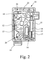
- the outer housing 11 has an inlet slot 12 for the locking pin 50, not shown (see FIG. 3).
- inlet slot 12 a arranged in the housing 11 rotary latch 13 moves. This is held by a arranged in the housing 11 pawl 14 in the closed position, as is absolutely customary in the door lock construction.
- Au- ⁇ engephinuse 11 is also an electric drive 15 for the pawl 14, which thus causes the lifting of the pawl 14 from the detent of the rotary latch 13 for the purpose of opening the door lock 10.
- the drive 15 is an electric drive motor which cooperates via a gear transmission 16 with a threaded spindle 17 and threaded rod 18 to actuate the pawl 14.
- a gear transmission 16 with a threaded spindle 17 and threaded rod 18 to actuate the pawl 14.
- electromagnet solenoid
- the microswitch 20 can detect, for example, the position of the pawl 14 and the position of the catch 13 directly, but can also record other functions, such as overheating of the motor of the drive 15 determine od.
- Micro switch 20 may be electromechanical microswitch.
- non-contact actuated microswitch 20 for example, according to the Hall principle or capacitive or inductive working or opto-electronic microswitches are known.
- the housing 11 to the outside with the exception of the inlet slot 12 for the locking block 50 is completely closed (fully enclosed). This improves the theft protection and moisture protection and fully exploits the possibilities of the known concept of the electronically controlled motor vehicle door lock.
- Fig. 3 shows a motor vehicle lock 10 for a driver's door, which is upgraded by an additional mechanical actuation option (master lock, controls slave locks). It is provided in the illustrated embodiment that on the housing 11 insertion for a first Bowden cable 24 to the outer opening and a second Bowden cable 25 for internal operation (secure, unlock, open) are provided. These Bowden cable insertion nozzles change in principle nothing on the concept of complete encapsulation by means of the outer housing 11, since these insertion can be made completely sealing.
- Fig. 3 and 4 of the drawing show a motor vehicle lock 10, which is characterized in that it is either for left entry, right entry or Center entry (tailgate, tailgate) can be used.
- the conception of this motor vehicle lock 10 thus allows a universal use of this motor vehicle lock, so that this motor vehicle lock 10 can be used inexpensively even with smaller series of motor vehicles.
- the components of this motor vehicle lock which have already been explained several times, have been provided, as far as can be seen, with the previously used reference numbers.
- the vehicle lock described above, shown in Figs. 3 and 4 is characterized in that the housing 11 is formed substantially symmetrically to its lying in or parallel to the plane of the rotary latch 13 and pawl 14 center plane 51 and at both to the center plane 51st parallel flat sides with an inlet slot 12 is provided. It can be seen in Fig. 4, the center plane 51 shown therefore particularly good, because here too the housing 11 consists of two half-shells, which are made of plastic, provided with metal reinforcing plates and clipped together.
- the above-described construction of the motor vehicle lock according to the invention with an inlet slot 12 on each flat side of the housing 11 allows easy installation of the door lock for left inlet of the locking block 50 or right inlet of the locking block 50 or middle entrance of the locking block 50, for example, on a tailgate or tailgate.
- One and the same motor vehicle lock can thus ultimately be used for all door and flap locks, even for a lock on the hood.
- Even smaller series of motor vehicles can be inexpensively equipped with this motor vehicle lock, since the number of pieces is at least doubled compared to previously known concepts.
- Fig. 3 is additionally indicated below as a separate part that adapted to the shape of the inlet slot 12 cap 52 'may be provided as a separate component.
- This closure cap 52 ' is attachable to the housing 11 for closing the inlet slot 12, which is currently not used, in which therefore does not occur in the intended installation position of the housing 11 of the locking block 50.
- this closure cap 52 ' can be inserted into the inlet slot 12 and locked therein on the housing 11.
- the cap 52 ' is supplied with the delivery of the motor vehicle lock and mounted on the housing 11 at the corresponding inlet slot 12, which is not used when installed in the motor vehicle door.
- the housing 11 is also completely closed in this respect, with the exception of the inlet slot 12 serving for the entry of the locking pin 50.
- the dot-dash line also indicates how a component, which is shown in FIGS. 5 and 6, can be attached to the housing 11 of the motor vehicle door lock according to the invention.
- Such locking block guides are known from the prior art for a long time, one knows here arcuate or wedge-shaped guides, guides with support arm, etc. The state of the art is extensive. In most cases, such locking pin guides made of plastic and are integrated as a built-in part in the housing 11.
- a closing block guide 52 is intended to guide the locking block 50 on three sides, not only upwards and downwards (in the case of vertical installation of the motor vehicle lock, as is usual on a side door).
- the inlet slot 12 associated locking pin guide 52 is provided as a separate component, mirror-symmetrical to a plane and the housing 11 is selectively attachable to one of the two flat sides , As an alternative (this is shown in Figs.
- the inlet slots 12th associated closing block guides 52 are provided as separate components, one designed for attachment to a flat side and the other for attachment to the other flat side, and that ultimately one of the two locking pin guides 52 is attached to the associated flat side of the housing 11.
- FIGS. 5 and 6 show this version of the locking pin guide 52 to be produced separately for the left inlet and the right inlet respectively.
- FIGS. 3 and 4 show this locking pin guide 52 in an alternative dot-dash line in the position attached to the housing 11.
- the illustrated embodiment is characterized in that the locking pin guide 52 on the housing 11 can be latched.
- the locking pin guide 52 is also made of thermoplastic material in the illustrated embodiment.
- the housing 11 is provided with latching receptacles 53 for latching moldings 54, 55, 56 on the locking pin guide 52. It is provided here that the locking receptacles 53 are arranged on a narrow side of the housing 11 and can be used for both positions.
- Fig. 7 shows this constructive alternative to a rotary latch lock in two variants.
- Fig. 7a shows such a Wip fallenschivity with locking pin 50 and a latch 61, which supports from below, so claimed pressurized locks.
- Fig. 7b shows the variant of a Wipp fallensches with locking pin 50 and a latch 61 which hooks from above, so claimed to train locks.
Description
Die Erfindung betrifft ein Kraftfahrzeug-Türschloß oder -Klappenschloß mit den Merkmalen des Oberbegriffs von Anspruch 1. Im folgenden wird nur der Begriff Kraftfahrzeugschloß verwendet.The invention relates to a motor vehicle door lock or -klappenschloß with the features of the preamble of
Das bekannte Kraftfahrzeugschloß von dem die Erfindung ausgeht (US-A-4,679,836), hat ein Gehäuse, das im wesentlichen symmetrisch zu seiner Mittelebene ausgebildet und an beiden zur Mittelebene parallelen Flachseiten mit einem Einlaufschlitz für den Schließkloben versehen ist. Die Schloßmechanik und ein eventueller elektrischer Antrieb ist außerhalb dieser mit den Einlaufschlitzen versehenen mechanischen Einheit angeordnet. An der Flachseite des Gehäuses dieses Kraftfahrzeugschlosses befindet sich in einer Ausnehmung ein Betätigungsarm einer Sperrklinke, der von einem Betätigungshebel einer von außen her an der Flachseite angesetzten Schloßmechanik-Baugruppe betätigt werden kann. Ein Umbau von Linkseinlauf auf Rechtseinlauf bei diesem Kraftfahrzeugschloß erfordert ein Umsetzen der Schloßmechanik-Baugruppe gegenüber dem Außengehäuse des Kraftfahrzeugschlosses.The well-known motor vehicle lock from which the invention proceeds (US-A-4,679,836), has a housing which is formed substantially symmetrically to its median plane and is provided at both parallel to the median plane flat sides with an inlet slot for the Schließkloben. The lock mechanism and a possible electric drive is arranged outside of this provided with the inlet slots mechanical unit. On the flat side of the housing of this motor vehicle lock is located in a recess, an actuating arm of a pawl, which can be actuated by an actuating lever of an externally attached to the flat side lock mechanism assembly. A conversion from left entry to right entry in this motor vehicle lock requires a conversion of the lock mechanism assembly relative to the outer housing of the motor vehicle lock.
Bekannt sind auch Kraftfahrzeugschlösser, die asymmetrisch aufgebaut sind und einen elektrischen Antrieb für die Sperrklinke aufweisen, der eine motorische Öffnung der Sperrklinke erlaubt (EP-A-0 589 158).Automotive locks are also known, which are constructed asymmetrically and have an electric drive for the pawl, which allows a motorized opening of the pawl (EP-A-0 589 158).
Schließlich ist für sich ein Kraftfahrzeugschloß mit einem Außengehäuse mit einem Einlaufschlitz für einen Schließkloben bekannt (DE-A-19 64 260), bei dem anstelle einer Kombination aus Drehfalle und Sperrklinke eine sich im Einlauf schlitz bewegende, im Gehäuse angeordnete Rastklinke vorgesehen ist, die mit einer entsprechenden Rastung am Schließkloben direkt zusammenwirkt, um den Schließkloben zu sperren oder freizugeben.Finally, a motor vehicle lock with an outer housing with an inlet slot for a locking block is known (DE-A-19 64 260), in which instead of a combination of rotary latch and pawl in the inlet slot moving, arranged in the housing latch is provided which interacts directly with a corresponding detent on the locking bolt to lock or unlock the locking pin.
Der Lehre liegt das Problem zugrunde, den Diebstahlschutz zu verbessern und das Schloß gegen Feuchtigkeit zu schützen und gleichzeitig die Anzahl benötigter Schloßtypen zu verringern.The teaching is based on the problem of improving the theft protection and to protect the lock against moisture while reducing the number of required lock types.
Die zuvor aufgezeigte Aufgabe ist bei einem Kraftfahrzeugschloß mit den Merkmalen des Oberbegriffs von Anspruch 1 durch die Merkmale des kennzeichnenden Teils von Anspruch 1 gelöst. Bevorzugte Ausgestaltungen und Weiterbildungen ergeben sich aus den Unteransprüchen.The aforementioned object is achieved in a motor vehicle lock with the features of the preamble of
Die aus dem Stand der Technik, von dem die Erfindung ausgeht, bekannte Konzeption der Minimierung mechanischer Bauteile eines Kraftfahrzeugschlosses und Ersatz der bislang üblichen Schließmechanik mit den verschiedenen Hebeln durch eine entsprechende elektronische Ansteuerung wird nach der Lehre der Erfindung dadurch optimiert, daß nunmehr das Außengehäuse weitestgehend gekapselt wird. Dadurch wird ein umfassender Diebstahlschutz erreicht, da das Innere des Gehäuses, insbesondere also die Sperrklinke, diebstahlgeschützt ist. Die komplette Abdichtung des Innenraums des Gehäuses schützt umfassend gegen Feuchtigkeit. Möglich wird dies durch Ausnutzung der Tatsache, daß elektrische Leiterbahnen zu elektrischen Anschlußeinrichtungen ohne weiteres abgedichtet durch die Gehäusewand gerührt werden können. Was bleibt ist also nur der Einlaufschlitz des Schließklobens, der aber auch mit aus dem Stand der Technik bekannten Maßnahmen abgedichtet werden kann, sofern das erforderlich ist.The known from the prior art, from which the invention proceeds, known concept of minimizing mechanical components of a motor vehicle lock and replacement of the usual locking mechanism with the various levers by a corresponding electronic control is optimized according to the teachings of the invention in that now the outer housing as far as possible is encapsulated. As a result, a comprehensive theft protection is achieved because the interior of the housing, in particular so the pawl, is theft-proof. The complete sealing of the interior of the housing provides comprehensive protection against moisture. This is made possible by exploiting the fact that electrical conductors can be easily sealed to electrical connection devices by the housing wall to be stirred. So what remains is only the inlet slot of the locking bolt, but which can also be sealed with known from the prior art measures, if that is necessary.
Die Symmetrie des Gehäuse mit zwei Einlaufschlitzen für den Schließkloben erlaubt es, das Kraftfahrzeugschloß wahlweise für Linkseinlauf oder Rechtseinlauf einzusetzen (oder Mitteleinlauf bei Heckklappe, Hecktür). Damit werden auch kleinere Serien wirtschaftlich produzierbar, da die Gesamtstückzahl des Kraftfahrzeug-Türschlosses des benötigten Typs sich verdoppelt bzw. vervielfacht.The symmetry of the housing with two inlet slots for the Schließkloben allows to use the motor vehicle lock either for left entry or right inlet (or center inlet at tailgate, rear door). This also smaller series are economically produced, since the total number of pieces of motor vehicle door lock of the required type doubles or multiplies.
Im folgenden wird die Erfindung anhand einer lediglich Ausführungsbeispiele darstellenden Zeichnung näher erläutert. In der Zeichnung zeigt
- Fig. 1
- eine schematische Darstellung einer Türschließanlage eines Kraftfahrzeugs nach Konzept der Erfindung,
- Fig. 2
- das Kraftfahrzeug-Türschloß der Schließanlage aus Fig. 1,
- Fig. 3
- in einer Ansicht von einer Flachseite her ein weiteres Ausführungsbeispiel eines Kraftfahrzeug-Türschlosses,
- Fig. 4
- das Kraftfahrzeug-Türschloß aus Fig. 3 in einer Ansicht von einer Schmalseite her,
- Fig. 5
- in einer Ansicht in Einlaufrichtung eine Schließkloben-Führung für ein Kraftfahrzeug-Türschloß gemäß Fig. 3,
- Fig. 6
- die Schließkloben-Führung aus Fig. 5 in einer Ansicht von oben,
- Fig. 7
- schematisch zwei Alternativen (a; b) einer Kombination aus Rastklinke und Schließkloben, die die Kombination aus Drehfalle, Sperrklinke und Schließkloben ersetzt.
- Fig. 1
- a schematic representation of a door locking system of a motor vehicle according to the concept of the invention,
- Fig. 2
- the motor vehicle door lock of the locking system of FIG. 1,
- Fig. 3
- in a view from a flat side forth another embodiment of a motor vehicle door lock,
- Fig. 4
- the motor vehicle door lock of FIG. 3 in a view from a narrow side,
- Fig. 5
- in a view in the inlet direction a locking pin guide for a motor vehicle door lock according to FIG. 3,
- Fig. 6
- 5 shows the locking block guide from FIG. 5 in a top view,
- Fig. 7
- schematically two alternatives (a; b) of a combination of latch and locking pin, which replaces the combination of rotary latch, pawl and locking bolt.
Fig. 1 zeigt ein weitestgehend elektronisch gesteuertes Schließ- und Zentralverriegelungssystem für ein Kraftfahrzeug. Dieses ist ausschnittweise dargestellt.Fig. 1 shows a largely electronically controlled locking and central locking system for a motor vehicle. This is shown in fragmentary form.
Die zentrale Steuerelektronik 1, die an sich von der nicht dargestellten Kraftfahrzeugbatterie versorgt wird, ist im dargestellten Ausführungsbeispiel mit einer zusätzlichen Reservebatterie 2 oder einem anderen elektrischen Energiespeicher für einen Notfall versehen, so daß sie auch bei Ausfall der übrigen Kraftfahrzeugelektrik beispielsweise bei einem Unfall funktionstüchtig bleibt. Von einem tragbaren, vom Fahrer mitgeführten Sendemodul 3 (elektronischer Schlüssel / Smart Card) werden Steuersignale ausgesandt, die auf einen Empfänger 4 am Türaußengriff 5 an der Kraftfahrzeugkarosserie treffen. Der Empfänger 4 steht mit der Steuerelektronik 1 in Verbindung. Der Türaußengriff 5 mit seiner Griffmulde 6 übermittelt nur noch ein elektrisches Steuersignal an die Steuerelektronik 1. Mechanische Verbindungen sind nicht mehr vorgesehen. In gleicher Weise werden auch vom Türinnengriff 7 nur elektronische Signale über entsprechende Mikroschalter erzeugt an die Steuerelektronik 1 übermittelt, und zwar im dargestellten Ausführungsbeispiel von der Griffmulde 8 ein Öffnungssignal und ggf. auch ein Entsicherungssignal und vom Sicherungstaster 9 ein Sicherungssignal.The
Das eigentliche Kraftfahrzeug-Türschloß 10, das auch ein Schloß einer Hecktür oder Heckklappe sein kann, im folgenden immer nur Kraftfahrzeugschloß, hat nur noch sehr wenige mechanische Teile. Zunächst weist es ein allseits geschlossenes Außengehäuse 11 auf, das wohl üblicherweise aus Kunststoff bestehen wird, beispielsweise aus zwei Halbschalen, die abdichtend zusammengefügt sind. Das Außengehäuse 11 weist einen Einlaufschlitz 12 für den nicht dargestellten Schließkloben 50 auf (siehe Fig. 3). Für diese und die weitere Erläuterung wird gleichzeitig auf Fig. 2 der Zeichnung verwiesen. Im Einlaufschlitz 12 bewegt sich eine im Gehäuse 11 angeordnete Drehfalle 13. Diese wird von einer im Gehäuse 11 angeordneten Sperrklinke 14 in Schließstellung gehalten, wie das an sich im Türschloßbau absolut üblich ist. Im Au-βengehäuse 11 befindet sich auch ein elektrischer Antrieb 15 für die Sperrklinke 14, der also das Ausheben der Sperrklinke 14 aus der Rast der Drehfalle 13 zum Zwecke des Öffnens des Türschlosses 10 bewirkt.The actual motor
Im dargestellten Ausführungsbeispiel handelt es sich beim Antrieb 15 um einen elektrischen Antriebsmotor, der über ein Zahnradgetriebe 16 mit einer Gewindespindel 17 und Gewindestange 18 zusammenwirkt, um die Sperrklinke 14 zu betätigen. Aus dem Stand der Technik sind viele andere Alternativen, beispielsweise mit einem Elektromagneten (Solenoid) bekannt. Darauf darf verwiesen werden.In the illustrated embodiment, the
Außen am Gehäuse 11 ist eine elektrische Anschlußeinrichtung 19 für die elektrischen Anschlüsse vom Antrieb 15 und von Mikroschaltern 20, die im Gehäuse 11 angeordnet sind, angeordnet. Die Mikroschalter 20 können beispielsweise die Stellung der Sperrklinke 14 und die Stellung der Drehfalle 13 unmittelbar erfassen, können aber auch noch sonstige weitere Funktionen aufnehmen, beispielsweise eine Überhitzung des Motors des Antriebs 15 feststellen od. dgl. Mikroschalter 20 können elektromechanische Mikroschalter sein. Heutzutage sind jedoch auch berührungslos betätigbare Mikroschalter 20, beispielsweise nach dem Hall-Prinzip oder auch kapazitiv oder induktiv arbeitend oder auch optoelektronische Mikroschalter bekannt.Outside the
Es kann vorgesehen werden, daß alle Leiterbahnen zur elektrischen Anschlußeinrichtung 19 in das Kunststoffmaterial des Gehäuses 11 eingegossen sind, wie das an sich für entsprechende Gehäuseteile aus dem Stand der Technik bekannt ist. Jedenfalls ist die elektrische Anschlußeinrichtung 19 über ein entsprechendes elektrisches Verbindungskabel 21 bzw. ein entsprechendes Bussystem mit der Steuerelektronik 1 verbunden. Entsprechendes gilt für die anderen Baugruppen der Verriegelungsanlage.It can be provided that all tracks are cast into the plastic material of the
Vorgesehen ist, daß das Gehäuse 11 nach außen mit Ausnahme des Einlaufschlitzes 12 für den Schließkloben 50 komplett geschlossen (voll gekapselt) ist. Das verbessert den Diebstahlschutz und den Feuchtigkeitsschutz und nutzt die Möglichkeiten des bekannten Konzepts des elektronisch gesteuerten Kraftfahrzeug-Türschlosses in vollem Umfange aus.It is provided that the
Für die elektronisch-steuerungstechnische Funktion eines Kraftfahrzeug-Türschlosses der in Rede stehenden Art darf im übrigen auf den Offenbarungsgehalt der EP - A - 0 589 158 hingewiesen werden, der in vollem Umfange auch zum Offenbarungsgehalt der vorliegenden Patentanmeldung gemacht wird.For the electronic-control function of a motor vehicle door lock of the type in question may otherwise be pointed to the disclosure of EP - A - 0 589 158, which is also made to the full extent of the disclosure content of the present patent application.
Das Ausführungsbeispiel in Fig. 3 zeigt ein Kraftfahrzeugschloß 10 für eine Fahrertür, das durch eine zusätzliche mechanische Betätigungsmöglichkeit aufgerüstet ist (Masterschloß, steuert Slaveschlösser). Dabei ist im dargestellten Ausführungsbeispiel vorgesehen, daß am Gehäuse 11 Einführstutzen für einen ersten Bowdenzug 24 zur Außenöffnung und einen zweiten Bowdenzug 25 für Innenbetätigung (sichern, entsichern, öffnen) vorgesehen sind. Auch diese Bowdenzug-Einführstutzen ändern im Grundsatz nichts am Konzept der vollständigen Kapselung mittels des Aussengehäuses 11, da diese Einführstutzen vollständig abdichtend gestaltet werden können.The embodiment in Fig. 3 shows a
Durch die zuvor erläuterte zusätzliche mechanische Betätigbarkeit des Kraftfahrzeugschlosses 10 ist der herstellungstechnische Aufwand natürlich wieder erheblich größer. Das widerspricht im Grundsatz dem Konzept der vollelektronischen Gestaltung des Kraftfahrzeugschlosses 10, ist aber manchmal aus Gründen nationaler Vorschriften nicht vermeidbar. Interessant ist aber die modulartige Gestaltung dieser Konstruktion. Aus einem Grundschloß mit dem einheitlichen Außengehäuse 11 lassen sich alle denkbaren Varianten durch Hinzufügen von Standardbauteilen aufrüsten.Due to the above-described additional mechanical operability of the
Fig. 3 und 4 der Zeichnung zeigen ein Kraftfahrzeugschloss 10, das sich dadurch auszeichnet, daß es wahlweise für Linkseinlauf, Rechtseinlauf oder Mitteleinlauf (Hecktür, Heckklappe) eingesetzt werden kann. Die Konzeption dieses Kraftfahrzeugschlosses 10 erlaubt also einen universellen Einsatz dieses Kraftfahrzeugschlosses, so daß dieses Kraftfahrzeugschloß 10 auch bei kleineren Bauserien von Kraftfahrzeugen kostengünstig eingesetzt werden kann. Die zuvor schon mehrfach erläuterten Bauteile dieses Kraftfahrzeugschlosses sind, soweit erkennbar, mit den zuvor verwendeten Bezugszeichen versehen worden.Fig. 3 and 4 of the drawing show a
Das zuvor erläuterte, in den Fig. 3 und 4 dargestellte Kraftfahrzeugschloß zeichnet sich dadurch aus, daß das Gehäuse 11 im wesentlichen symmetrisch zu seiner in der oder parallel zu der Ebene der Drehfalle 13 und Sperrklinke 14 liegenden Mittelebene 51 ausgebildet und an beiden zur Mittelebene 51 parallelen Flachseiten mit einem Einlaufschlitz 12 versehen ist. Man erkennt in Fig. 4 die Mittelebene 51 eingezeichnet deshalb besonders gut, weil auch hier das Gehäuse 11 aus zwei Halbschalen besteht, die in Kunststoff ausgeführt, mit metallischen Verstärkungsplatten versehen und miteinander verclipst sind.The vehicle lock described above, shown in Figs. 3 and 4 is characterized in that the
Die zuvor erläuterte Konstruktion des erfindungsgemäßen Kraftfahrzeugschlosses mit einem Einlaufschlitz 12 auf jeder Flachseite des Gehäuses 11 erlaubt den problemlosen Einbau des Türschlosses für Linkseinlauf des Schließklobens 50 oder Rechtseinlauf des Schließklobens 50 oder für Mitteleinlauf des Schließklobens 50 beispielsweise an einer Hecktür oder Heckklappe. Ein und dasselbe Kraftfahrzeugschloß kann also letztlich für alle Tür- und Klappenschlösser, sogar für ein Schloß an der Motorhaube, eingesetzt werden. Auch kleinere Bauserien von Kraftfahrzeugen lassen sich mit diesem Kraftfahrzeugschloß kostengünstig ausrüsten, da die Stückzahl gegenüber bisher bekannten Konzeptionen mindestens verdoppelt ist.The above-described construction of the motor vehicle lock according to the invention with an
Zuvor ist schon einmal angedeutet worden, daß der Tatsache, daß das Kraftfahrzeugschloß sehr flach baut bzw. bauen kann, wenn die Hebel im Inneren des Gehäuses 11 richtig angeordnet sind, besondere Bedeutung zukommt. Das zeigt das dargestellte Ausführungsbeispiel gemäß Fig. 3 und insbesondere Fig. 4. Für die Integration der zuvor angesprochenen Bowdenzüge 24, 25 ist hier vorgesehen, daß diese mit ihren Einführstutzen an einer Schmalseite des Gehäuses 11 austreten. An der Lage der Bowdenzüge 24, 25 ändert sich also bei Einsatz des Kraftfahrzeug-Türschlosses für Linkseinlauf oder Rechtseinlauf im Prinzip nichts. Sie treten immer in Richtung der Mittelebene 51 aus dem Gehäuse 11 aus.Previously, it has already been indicated that the fact that the motor vehicle lock can be built or built very flat when the levers are arranged correctly inside the
In Fig. 3 ist unten als separates Teil zusätzlich angedeutet, daß eine an die Form des Einlaufschlitzes 12 angepaßte Verschlußkappe 52' als separates Bauteil vorgesehen sein kann. Diese Verschlußkappe 52' ist am Gehäuse 11 zum Verschließen des Einlaufschlitzes 12 anbringbar, der gerade nicht benutzt wird, in den also bei der vorgesehenen Einbaulage des Gehäuses 11 der Schließkloben 50 nicht eintritt. Insbesondere ist diese Verschlußkappe 52' in den Einlaufschlitz 12 einschiebbar und darin am Gehäuse 11 verrastbar. Die Verschlußkappe 52' wird bei der Lieferung des Kraftfahrzeugschlosses mitgeliefert und beim Einbau in die Kraftfahrzeugtür am Gehäuse 11 am entsprechenden Einlaufschlitz 12, der nicht benutzt wird, angebracht. Dadurch ist das Gehäuse 11 auch insoweit komplett geschlossen mit Ausnahme des dem Einlaufen des Schließklobens 50 dienenden Einlaufschlitzes 12.In Fig. 3 is additionally indicated below as a separate part that adapted to the shape of the
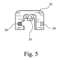
In Fig. 3 und Fig. 4 ist ferner strichpunktiert angedeutet, wie ein Bauteil, das in Fig. 5 und Fig. 6 dargestellt ist, am Gehäuse 11 des erfindungsgemäßen Kraftfahrzeug-Türschlosses angebracht werden kann. Mitunter ist es nämlich erforderlich, für den Schließkloben 50 eine zusätzliche Schließkloben-Führung 52 vorzusehen. Solche Schließkloben-Führungen sind aus dem Stand der Technik seit langem bekannt, man kennt hier bogenförmige oder keilförmige Führungen, Führungen mit Stützschwinge etc.. Der Stand der Technik dazu ist umfangreich. Zumeist bestehen solche Schließkloben-Führungen aus Kunststoff und sind als Einbauteil in das Gehäuse 11 integriert.In FIGS. 3 and 4, the dot-dash line also indicates how a component, which is shown in FIGS. 5 and 6, can be attached to the
Eine Schließkloben-Führung 52 soll im Regelfall den Schließkloben 50 an drei Seiten führen, nicht nur nach oben und nach unten (bei vertikalem Einbau des Kraftfahrzeugschlosses wie an einer Seitentür üblich). Insbesondere unter diesem Aspekt, aber auch aus einbautechnischen Gründen ist bei der hier vorgestellten Konzeption vorgesehen, daß eine dem Einlaufschlitz 12 zugeordnete Schließkloben-Führung 52 als separates Bauteil vorgesehen, spiegelsymmetrisch zu einer Ebene ausgeführt und am Gehäuse 11 wahlweise an einer der beiden Flachseiten anbringbar ist. Als Alternative (diese ist in den Fig. 5 und 6 dargestellt) kann man vorsehen, daß den Einlaufschlitzen 12 zugeordnete Schließkloben-Führungen 52 als separate Bauteile vorgesehen sind, eine für die Anbringung an einer Flachseite und die andere für die Anbringung an der anderen Flachseite ausgeführt, und daß letztlich eine der beiden Schließkloben-Führungen 52 an der zugeordneten Flachseite des Gehäuses 11 anbringbar ist. Fig. 5 und 6 zeigen diese Version der für Linkseinlauf und Rechtseinlauf jeweils separat herzustellenden Schließkloben-Führung 52, Fig. 3 und 4 zeigen diese Schließkloben-Führung 52 in der einen Alternative strichpunktiert in der am Gehäuse 11 angebrachten Position.As a rule, a
Das dargestellte Ausführungsbeispiel zeichnet sich dadurch aus, daß die Schließkloben-Führung 52 am Gehäuse 11 einrastbar ist. Wie auch im Stand der Technik für andere Schließkloben-Führungen üblich, besteht auch im dargestellten Ausführungsbeispiel die Schließkloben-Führung 52 aus thermoplastischem Kunststoff.The illustrated embodiment is characterized in that the locking
Bei dem dargestellten Ausführungsbeispiel ist ferner vorgesehen, daß das Gehäuse 11 mit Rastaufnahmen 53 für Rastformteile 54, 55, 56 an der Schließkloben-Führung 52 versehen ist. Dabei ist hier vorgesehen, daß die Rastaufnahmen 53 an einer Schmalseite des Gehäuses 11 angeordnet und für beide Positionen nutzbar sind.In the illustrated embodiment, it is further provided that the
Man erkennt an der unteren Schmalseite des Gehäuses 11 in Fig. 3 rechts eine nutförmige Rastaufnahme 53 für das hakenförmige Rastformteil 54 an der Schließkloben-Führung 52, etwa in der Mitte oberhalb des Schließklobens 50 eine weitere Rastaufnahme 53 für das ebenfalls hakenförmige Rastformteil 55 mittig an der Schließkloben-Führung 52 und in Fig. 3 nicht dargestellt, jedoch ohne weiteres vorstellbar eine weitere Rastaufnahme für das als Schlitzzapfen ausgeführte Rastformteil 56 an der Schließkloben-Führung 52.It can be seen on the lower narrow side of the
Man kann mit der Schließkloben-Führung 52, die nachträglich auf das Gehäuse 11 aufgeclipst wird, auch eine vorzügliche Abdichtung des Einlaufschlitzes 12 gegen Feuchtigkeitseintritt realisieren. Wo und wie die Schließkloben-Führung 52 mit dem Gehäuse 11 verbunden wird, bleibt der jeweiligen Fertigungseinteilung überlassen. Man kann das sowohl beim Schloßhersteller als auch beim Fahrzeughersteller bei der Montage am Band realisieren.It is possible with the locking
Neben Kraftfahrzeugschlössern, bei denen eine Drehfalle 13 durch eine Sperrklinke 14 in ihrer Schließlage gehalten wird, sind auch Kraftfahrzeugschlösser bekannt, bei denen anstelle der Kombination aus Drehfalle 13 und Sperrklinke 14 nur eine einzige Rastklinke 61 vorgesehen ist, die mit einem eine entsprechende Rastung aufweisenden Schließkloben 50 direkt zusammenwirkt. Die Lehre der Erfindung ist auch bei einem derartig ausgestalteten Kraftfahrzeugschloß anwendbar, worauf Anspruch 2 hinweist. Anstelle einer entsprechenden Sperrung oder Betätigung der Sperrklinke 14 erfolgt dann eine entsprechende Sperrung oder Betätigung der alleinigen Rastklinke 61. Fig. 7 zeigt diese konstruktive Alternative zu einem Drehfallenschloß in zwei Varianten. Fig. 7a zeigt ein solches Wippfallenschloß mit Schließkloben 50 und einer Rastklinke 61, die von unten stützend, also auf Druck beansprucht sperrt. Demgegenüber zeigt Fig. 7b die Variante eines Wippfallenschlosses mit Schließkloben 50 und einer Rastklinke 61, die von oben hakend, also auf Zug beansprucht sperrt.In addition to motor vehicle locks, in which a
Claims (11)
- Door lock or hood lock for motor vehicles,
with an outer housing (11) having an inlet slot (12) for a locking hook (50),
with a rotary latch (13) which is arranged in the outer housing (11), moves in the inlet slot (12) and with which the locking hook (50) can come into engagement, and with a detent pawl (14) which is likewise arranged in the outer housing (11) and keeps the rotary latch (13) in the locking position, or
with a latching pawl (61) which is arranged in the outer housing (11), moves in the inlet slot (12) and directly interacts with a corresponding latching position on the locking hook (50) in order to block or release the locking hook (50),
the outer housing (11) being formed essentially symmetrically with respect to its central plane (51) situated in the or parallel to the plane of the rotary latch (13) and detent pawl (14) or the latching pawl (61), and
the outer housing (11) being provided with an inlet slot (12) on both flat sides, which are parallel to the central plane (51),
characterized
in that the outer housing (11) is very substantially encapsulated to the outside with the exception of the inlet slot (12) for the locking hook (50) and, if appropriate, insertion nipples (23) for one or two Bowden cables (24; 25), and
in that an electric drive (15) for the detent pawl (14) or the latching pawl (61) is arranged in the outer housing (11) and an electric connecting device (19) for the electrical connections of the drive (15) and of optionally present micro switches (20) in the outer housing (11) is arranged on the outside of the outer housing (11). - Lock for motor vehicles according to Claim 1, characterized in that the external connection or the external connections (19; 24; 25) is or are arranged on narrow sides of the housing (11).
- Lock for motor vehicles according to Claim 1 or 2, characterized in that lever elements for actuating and blocking the detent pawl (14) or latching pawl (61) are arranged in the interior of the outer housing (11) on the right-hand side and left-hand side or above and below the rotary latch (13) and detent pawl (14) or the latching pawl (61).
- Lock for motor vehicles according to one of Claims 1 to 3, characterized in that a closure cap (52') which is matched to the shape of the inlet slot (12) is provided as a separate component and can be fastened to the outer housing (11) in order to close the respectively unused opening of the inlet slot (12), in particular can be pushed into the inlet slot (12) and/or can be latched into place on the outer housing (11).
- Lock for motor vehicles according to one of Claims 1 to 4, characterized in that a locking hook guide (52) assigned to the inlet slot (12) is provided as a separate component, is formed mirror-symmetrically with respect to a plane and can be fitted according to choice on one of the two flat sides on the outer housing (11).
- Lock for motor vehicles according to one of Claims 1 to 4, characterized in that locking hook guides (52) assigned to the inlet slot (12) are provided as separate components, one designed for fitting on one flat side and the other for fitting on the other flat side, and in that, finally, one of the two locking hook guides (52) can be fitted on the associated flat side of the outer housing (11).
- Lock for motor vehicles according to Claim 5 or 6, characterized in that the locking hook guide (52) can be latched into place on the outer housing (11).
- Lock for motor vehicles according to one of Claims 5 to 7, characterized in that the locking hook guide (52) is composed of thermoplastic.
- Lock for motor vehicles according to Claim 7 and, if appropriate, Claim 8, characterized in that the outer housing (11) is provided with latching receptacles (53) for moulded latching parts (54, 55, 56) on the locking hook guide (52).
- Lock for motor vehicles according to Claim 9, characterized in that the latching receptacles (53) are arranged on a narrow side of the outer housing (11) and can be used for both positions.
- Lock for motor vehicles according to one of Claims 1 to 10, characterized in that the outer housing (11) comprises two half shells which are realized in plastic and are provided with metallic reinforcing plates.
Priority Applications (1)
| Application Number | Priority Date | Filing Date | Title |
|---|---|---|---|
| DE29624351U DE29624351U1 (en) | 1995-10-13 | 1996-09-27 | Motor vehicle door lock or the like. |
Applications Claiming Priority (5)
| Application Number | Priority Date | Filing Date | Title |
|---|---|---|---|
| DE19538042 | 1995-10-13 | ||
| DE19538042 | 1995-10-13 | ||
| DE19545722 | 1995-12-07 | ||
| DE19545722A DE19545722A1 (en) | 1995-10-13 | 1995-12-07 | Motor vehicle door lock or the like. |
| PCT/DE1996/001857 WO1997013942A2 (en) | 1995-10-13 | 1996-09-27 | Door lock for motor vehicles or the like |
Publications (2)
| Publication Number | Publication Date |
|---|---|
| EP0854962A2 EP0854962A2 (en) | 1998-07-29 |
| EP0854962B1 true EP0854962B1 (en) | 2006-06-21 |
Family
ID=26019444
Family Applications (1)
| Application Number | Title | Priority Date | Filing Date |
|---|---|---|---|
| EP96945471A Expired - Lifetime EP0854962B1 (en) | 1995-10-13 | 1996-09-27 | Door lock or hood lock for motor vehicles |
Country Status (9)
| Country | Link |
|---|---|
| US (1) | US6050117A (en) |
| EP (1) | EP0854962B1 (en) |
| JP (1) | JPH11515067A (en) |
| BR (1) | BR9611450A (en) |
| CZ (1) | CZ295793B6 (en) |
| DE (1) | DE59611359D1 (en) |
| ES (1) | ES2264147T3 (en) |
| HU (1) | HUP9900503A3 (en) |
| WO (1) | WO1997013942A2 (en) |
Families Citing this family (70)
| Publication number | Priority date | Publication date | Assignee | Title |
|---|---|---|---|---|
| GB9915432D0 (en) * | 1999-07-01 | 1999-09-01 | Meritor Light Vehicle Sys Ltd | Latch assembly |
| DE19728967C2 (en) * | 1997-07-01 | 2001-07-05 | Brose Fahrzeugteile | Transmission device for mechanical actuating movements and / or electrical signals between a door operating device and a door locking device of a motor vehicle door |
| DE19831260A1 (en) * | 1998-07-11 | 2000-01-13 | Mannesmann Vdo Ag | Locking device, in particular for motor vehicle doors |
| US6343494B2 (en) * | 1998-08-11 | 2002-02-05 | Mannesmann Vdo Ag | Locking device |
| DE19916949B4 (en) * | 1998-08-25 | 2004-08-19 | Kiekert Ag | Housing, in particular lock housing for a motor vehicle door lock, gear housing or similar cable carrier |
| US6189256B1 (en) * | 1999-04-12 | 2001-02-20 | Mark A. Boys | Method and apparatus enabling remote release of hooks and hook assemblies to free fishing lures |
| EP1045093B1 (en) * | 1999-04-16 | 2005-06-01 | Brose Schliesssysteme GmbH & Co. KG | Lock for a motor vehicle door or the like |
| DE19920278B4 (en) * | 1999-05-04 | 2012-03-22 | Kiekert Ag | Motor vehicle door lock |
| US20040144142A1 (en) * | 1999-11-18 | 2004-07-29 | Strattec Security Corporation | Modular vehicle door lock and latch system and method |
| US6530251B1 (en) | 1999-11-18 | 2003-03-11 | Strattec Security Corporation | Modular vehicle door lock and latch system and method |
| JP3773731B2 (en) * | 1999-12-24 | 2006-05-10 | 株式会社大井製作所 | Door lock device |
| DE50014907D1 (en) * | 1999-12-31 | 2008-02-21 | Brose Schliesssysteme Gmbh | Electromotive actuator for a motor vehicle lock |
| DE10000639B4 (en) * | 2000-01-11 | 2005-05-04 | Siemens Ag | Operating device for sliding door |
| GB0018101D0 (en) * | 2000-07-25 | 2000-09-13 | Meritor Light Vehicle Sys Ltd | Latch arrangement |
| EP1330584B1 (en) * | 2000-11-01 | 2014-06-11 | Southco, Inc. | Latching device |
| DE10100010B4 (en) * | 2001-01-02 | 2005-05-12 | Brose Schließsysteme GmbH & Co.KG | Motor vehicle door lock, designed as an electric lock, and method for assembling a motor vehicle door lock designed as an electric lock |
| DE10164829B4 (en) * | 2001-01-02 | 2006-07-13 | Brose Schließsysteme GmbH & Co.KG | Motor vehicle door lock, designed as an electric lock |
| US8225458B1 (en) | 2001-07-13 | 2012-07-24 | Hoffberg Steven M | Intelligent door restraint |
| GB0122634D0 (en) * | 2001-09-20 | 2001-11-14 | Meritor Light Vehicle Sys Ltd | Door release and engagement mechanism |
| DE10149478B4 (en) * | 2001-10-08 | 2007-02-15 | Siemens Ag | Door locking device |
| ES2250565T3 (en) | 2001-10-16 | 2006-04-16 | BROSE SCHLIESSSYSTEME GMBH & CO. KG | DOOR LOCK FOR CARS WITH CLOSURE UNIT AND CONTROL UNIT SEPARATED ONE OF THE OTHER. |
| ITTO20011000A1 (en) * | 2001-10-19 | 2003-04-19 | Atoma Roltra Spa | MODULAR LOCK FOR A VEHICLE DOOR AND DOOR PROVIDED WITH SUCH LOCK. |
| DE60217285T2 (en) * | 2002-03-19 | 2007-07-05 | Ford Global Technologies, LLC, Dearborn | Motor vehicle door system with locking indicator |
| DE10220732A1 (en) * | 2002-05-08 | 2003-12-24 | Brose Schliesssysteme Gmbh | Motor vehicle door lock or flap lock |
| DE10223563A1 (en) * | 2002-05-27 | 2003-12-11 | Siemens Ag | Motor vehicle door lock operating method for a vehicle door lock has a rotary latch, a detent pawl and a detent pawl catch |
| CZ299855B6 (en) * | 2002-10-31 | 2008-12-10 | Brano A.S. | Vehicle lock, particularly engine bonnet lock |
| US20040189016A1 (en) * | 2002-12-24 | 2004-09-30 | Aisin Seiki Kabushiki Kaisha | Torque transmitting member and door lock device |
| DE10341254A1 (en) * | 2003-06-02 | 2005-01-13 | Brose Schließsysteme GmbH & Co.KG | Electric component (EC) for a motor vehicle has control electronics and a plug-in connection for making an electric link between the EC and an overriding control device or another EC |
| US7261335B2 (en) * | 2003-11-14 | 2007-08-28 | Intier Automotive Closures Inc. | Power release side door latch with emergency release system |
| US20050134052A1 (en) * | 2003-12-23 | 2005-06-23 | Honeywell International Inc. | Pulsed electromagnetic application in vehicle door latch |
| US7878560B1 (en) * | 2004-09-20 | 2011-02-01 | Hanchett Entry Systems | Electromechanical locking device intended for remote access control |
| US8303018B2 (en) | 2007-01-04 | 2012-11-06 | Johnson Control Technology Company | Dynamic hook insert for a movable seat back |
| US20080224482A1 (en) * | 2007-02-15 | 2008-09-18 | Cumbo Francesco | Electrical Door Latch |
| US9260882B2 (en) | 2009-03-12 | 2016-02-16 | Ford Global Technologies, Llc | Universal global latch system |
| US8573657B2 (en) * | 2009-03-12 | 2013-11-05 | Ford Global Technologies, Llc | Latch mechanism |
| EP2424404B1 (en) * | 2009-04-27 | 2016-09-21 | Accuride International Inc. | Drawer slide and locking mechanism |
| US8844514B2 (en) * | 2010-07-22 | 2014-09-30 | General Electric Company | Latching system for an appliance |
| US8579068B2 (en) * | 2011-06-02 | 2013-11-12 | Ford Global Technologies, Llc | Hood latch and striker system for pedestrian protection |
| US9551166B2 (en) | 2011-11-02 | 2017-01-24 | Ford Global Technologies, Llc | Electronic interior door release system |
| JP6219943B2 (en) | 2012-07-18 | 2017-10-25 | アキュライド インターナショナル, インコーポレイテッドAccuride International, Inc. | Drawer slide and electrically actuated locking mechanism |
| DE102014217690B4 (en) | 2013-09-13 | 2022-09-22 | Ford Global Technologies, Llc | Method of configuring vehicle side door latch assemblies |
| US9416565B2 (en) | 2013-11-21 | 2016-08-16 | Ford Global Technologies, Llc | Piezo based energy harvesting for e-latch systems |
| US9809999B2 (en) * | 2013-11-25 | 2017-11-07 | The Eastern Company | Latch apparatus |
| FR3014472B1 (en) * | 2013-12-10 | 2017-10-06 | Inteva Products Llc | ASSEMBLY AND DOOR LATCH SYSTEM |
| DE102014001160A1 (en) * | 2014-01-31 | 2015-08-06 | Kiekert Aktiengesellschaft | Electric motor vehicle door lock with increased reliability |
| DE102014205371A1 (en) * | 2014-03-22 | 2015-09-24 | BROSE SCHLIEßSYSTEME GMBH & CO. KG | Motor vehicle lock arrangement |
| US10273725B2 (en) | 2014-05-13 | 2019-04-30 | Ford Global Technologies, Llc | Customer coaching method for location of E-latch backup handles |
| US9834964B2 (en) | 2014-05-13 | 2017-12-05 | Ford Global Technologies, Llc | Powered vehicle door latch and exterior handle with sensor |
| US10119308B2 (en) | 2014-05-13 | 2018-11-06 | Ford Global Technologies, Llc | Powered latch system for vehicle doors and control system therefor |
| US10323442B2 (en) | 2014-05-13 | 2019-06-18 | Ford Global Technologies, Llc | Electronic safe door unlatching operations |
| US9903142B2 (en) | 2014-05-13 | 2018-02-27 | Ford Global Technologies, Llc | Vehicle door handle and powered latch system |
| US9909344B2 (en) | 2014-08-26 | 2018-03-06 | Ford Global Technologies, Llc | Keyless vehicle door latch system with powered backup unlock feature |
| KR101808547B1 (en) * | 2015-06-26 | 2017-12-13 | 주식회사 우보테크 | Latch system for door |
| US9725069B2 (en) | 2015-10-12 | 2017-08-08 | Ford Global Technologies, Llc | Keyless vehicle systems |
| CN107227906B (en) * | 2016-03-25 | 2021-01-29 | 开开特股份公司 | Motor vehicle lock with cover |
| EP3239442B1 (en) * | 2016-04-29 | 2020-02-26 | FCA Italy S.p.A. | Key-operated unlocking of automotive power-operated key-cylinder-less door locks |
| US10550610B2 (en) | 2016-06-22 | 2020-02-04 | Ford Global Technologies, Llc | Inside override emergency handle for door release |
| US10227810B2 (en) | 2016-08-03 | 2019-03-12 | Ford Global Technologies, Llc | Priority driven power side door open/close operations |
| US10087671B2 (en) | 2016-08-04 | 2018-10-02 | Ford Global Technologies, Llc | Powered driven door presenter for vehicle doors |
| US10329823B2 (en) | 2016-08-24 | 2019-06-25 | Ford Global Technologies, Llc | Anti-pinch control system for powered vehicle doors |
| US10458171B2 (en) | 2016-09-19 | 2019-10-29 | Ford Global Technologies, Llc | Anti-pinch logic for door opening actuator |
| US10604970B2 (en) | 2017-05-04 | 2020-03-31 | Ford Global Technologies, Llc | Method to detect end-of-life in latches |
| DE102017124527A1 (en) * | 2017-10-20 | 2019-04-25 | Kiekert Ag | motor vehicle |
| US10907386B2 (en) | 2018-06-07 | 2021-02-02 | Ford Global Technologies, Llc | Side door pushbutton releases |
| US10800306B2 (en) | 2018-07-12 | 2020-10-13 | Ford Global Technologies, Llc | Pyrotechnic locking device |
| DE102018118494A1 (en) * | 2018-07-31 | 2020-02-06 | Kiekert Ag | MOTOR VEHICLE LOCK PARTICULAR MOTOR VEHICLE HOOD LOCK |
| US11346129B1 (en) | 2018-11-16 | 2022-05-31 | The Eastern Company | Latch apparatus |
| US20220251878A1 (en) * | 2018-11-16 | 2022-08-11 | The Eastern Company | Latch apparatus |
| US11572721B2 (en) | 2019-01-17 | 2023-02-07 | Strattec Security Corporation | Latch assembly |
| US11933082B2 (en) | 2020-03-23 | 2024-03-19 | Strattec Security Corporation | Cinching latch assembly |
Family Cites Families (11)
| Publication number | Priority date | Publication date | Assignee | Title |
|---|---|---|---|---|
| DE1142525B (en) * | 1958-08-12 | 1963-01-17 | Friedrich Wilhelm Kiekert | Motor vehicle door lock |
| FR1598109A (en) * | 1968-12-24 | 1970-06-29 | ||
| FR2548719B2 (en) * | 1982-07-19 | 1986-06-06 | Cousin Cie Ets A & M Freres | ELECTRIC SECURITY LOCK, ESPECIALLY FOR MOTOR VEHICLE DOORS |
| FR2559535B1 (en) * | 1984-02-13 | 1989-05-12 | Peugeot Aciers Et Outillage | LOCK FOR MOTOR VEHICLE DOOR |
| US4679836A (en) * | 1986-03-21 | 1987-07-14 | General Motors Corporation | Closure latch |
| JPH0625513B2 (en) * | 1987-10-31 | 1994-04-06 | 三井金属鉱業株式会社 | Waterproof and soundproof closed type locking device for vehicles |
| DE4031843A1 (en) * | 1989-10-20 | 1991-04-25 | Bocklenberg & Motte Bomoro | Lock for motor vehicle door - has cover plate made of plastics material |
| DE4100524A1 (en) * | 1990-01-19 | 1991-07-25 | Bocklenberg & Motte Bomoro | MOTOR VEHICLE DOOR LOCK, HOOD LOCK OR THE LIKE |
| GB9108447D0 (en) * | 1991-04-19 | 1991-06-05 | Rockwell Automotive Body Syst | Vehicle door latches |
| DE4228235C2 (en) * | 1992-08-25 | 2001-03-29 | Bayerische Motoren Werke Ag | Locking device for locks on doors of motor vehicles |
| DE4240013A1 (en) * | 1992-08-25 | 1994-06-01 | Bayerische Motoren Werke Ag | Remote controllable lock, in particular for motor vehicle doors |
-
1996
- 1996-09-27 WO PCT/DE1996/001857 patent/WO1997013942A2/en active IP Right Grant
- 1996-09-27 HU HU9900503A patent/HUP9900503A3/en unknown
- 1996-09-27 JP JP51461597A patent/JPH11515067A/en active Pending
- 1996-09-27 ES ES96945471T patent/ES2264147T3/en not_active Expired - Lifetime
- 1996-09-27 US US09/051,541 patent/US6050117A/en not_active Expired - Lifetime
- 1996-09-27 BR BR9611450A patent/BR9611450A/en not_active IP Right Cessation
- 1996-09-27 DE DE59611359T patent/DE59611359D1/en not_active Expired - Lifetime
- 1996-09-27 CZ CZ19981058A patent/CZ295793B6/en not_active IP Right Cessation
- 1996-09-27 EP EP96945471A patent/EP0854962B1/en not_active Expired - Lifetime
Also Published As
| Publication number | Publication date |
|---|---|
| CZ295793B6 (en) | 2005-11-16 |
| HUP9900503A3 (en) | 1999-11-29 |
| DE59611359D1 (en) | 2006-08-03 |
| JPH11515067A (en) | 1999-12-21 |
| US6050117A (en) | 2000-04-18 |
| BR9611450A (en) | 2000-03-14 |
| WO1997013942A3 (en) | 1997-09-25 |
| CZ105898A3 (en) | 1998-09-16 |
| WO1997013942A2 (en) | 1997-04-17 |
| HUP9900503A2 (en) | 1999-06-28 |
| EP0854962A2 (en) | 1998-07-29 |
| ES2264147T3 (en) | 2006-12-16 |
Similar Documents
| Publication | Publication Date | Title |
|---|---|---|
| EP0854962B1 (en) | Door lock or hood lock for motor vehicles | |
| EP0496736B1 (en) | Device for locking and unlocking closed doors for access to a motor vehicle | |
| DE19545722A1 (en) | Motor vehicle door lock or the like. | |
| EP1304433B1 (en) | Motor vehicle door lock with from each other separated closing unit and control unit | |
| EP1212499B1 (en) | Closing system, especially for motor vehicles | |
| DE10233485A1 (en) | Locking system for motor vehicle door has locking units that are spaced apart from control unit at location within vehicle door or hatch | |
| EP2920388B1 (en) | Motor vehicle door lock and method for selectively operating a motor vehicle door lock with or without a security device | |
| DE19943986B4 (en) | Locking system, especially for motor vehicles | |
| DE19957046A1 (en) | Electronic lock for automobile central locking system verifies correct insertion of electronically coded key and coded operating signal provided by key before lock can be operated | |
| EP3262258B1 (en) | Motor vehicle door lock | |
| DE19547728C2 (en) | Circuit arrangement with an electrical actuating device | |
| DE102016109566A1 (en) | Motor vehicle door lock system | |
| DE19924458B4 (en) | Motor vehicle door locking device | |
| EP0798437A1 (en) | Fastening device | |
| WO2021151423A1 (en) | Electrically actuatable motor vehicle lock | |
| DE10151022A1 (en) | Motor vehicle door lock with separate locking unit and control unit | |
| DE19649377A1 (en) | Motor vehicle door lock with corresponding closure block | |
| DE10100008B4 (en) | Sealed electrically operated lock assembly for motor vehicles, uses sealed box to house lock with external cam driven by shaft that passes through seal fitted to hole in cover of box | |
| EP2076644B1 (en) | Actuator | |
| DE102005018859A1 (en) | Sliding door and vehicle with sliding door | |
| DE19827132A1 (en) | Outside door handle assembly with remote control locking for motor vehicles | |
| EP1216334B1 (en) | Electromotively activated locking system and method for controlling the same | |
| DE3516732C1 (en) | Combined central-locking and securing system for closures on a motor vehicle | |
| DE19928230A1 (en) | Motor vehicle door lock has control device with control plate, control shaft or similar with axial and radial control cams in different positions; various control variants can be coded | |
| DE10110303A1 (en) | Door closure unit for vehicle, has coupling mechanism which includes connecting lead for signaling or illumination |
Legal Events
| Date | Code | Title | Description |
|---|---|---|---|
| PUAI | Public reference made under article 153(3) epc to a published international application that has entered the european phase |
Free format text: ORIGINAL CODE: 0009012 |
|
| 17P | Request for examination filed |
Effective date: 19980513 |
|
| AK | Designated contracting states |
Kind code of ref document: A2 Designated state(s): DE ES FR GB IT SE |
|
| 17Q | First examination report despatched |
Effective date: 19990429 |
|
| RAP1 | Party data changed (applicant data changed or rights of an application transferred) |
Owner name: BROSE SCHLIESSSYSTEME GMBH & CO. KG |
|
| GRAP | Despatch of communication of intention to grant a patent |
Free format text: ORIGINAL CODE: EPIDOSNIGR1 |
|
| RTI1 | Title (correction) |
Free format text: DOOR LOCK OR HOOD LOCK FOR MOTOR VEHICLES |
|
| GRAS | Grant fee paid |
Free format text: ORIGINAL CODE: EPIDOSNIGR3 |
|
| GRAA | (expected) grant |
Free format text: ORIGINAL CODE: 0009210 |
|
| AK | Designated contracting states |
Kind code of ref document: B1 Designated state(s): DE ES FR GB IT SE |
|
| REG | Reference to a national code |
Ref country code: GB Ref legal event code: FG4D Free format text: NOT ENGLISH |
|
| REF | Corresponds to: |
Ref document number: 59611359 Country of ref document: DE Date of ref document: 20060803 Kind code of ref document: P |
|
| PG25 | Lapsed in a contracting state [announced via postgrant information from national office to epo] |
Ref country code: SE Free format text: LAPSE BECAUSE OF FAILURE TO SUBMIT A TRANSLATION OF THE DESCRIPTION OR TO PAY THE FEE WITHIN THE PRESCRIBED TIME-LIMIT Effective date: 20060921 |
|
| GBT | Gb: translation of ep patent filed (gb section 77(6)(a)/1977) |
Effective date: 20060924 |
|
| REG | Reference to a national code |
Ref country code: ES Ref legal event code: FG2A Ref document number: 2264147 Country of ref document: ES Kind code of ref document: T3 |
|
| ET | Fr: translation filed | ||
| PLBE | No opposition filed within time limit |
Free format text: ORIGINAL CODE: 0009261 |
|
| STAA | Information on the status of an ep patent application or granted ep patent |
Free format text: STATUS: NO OPPOSITION FILED WITHIN TIME LIMIT |
|
| 26N | No opposition filed |
Effective date: 20070322 |
|
| PGFP | Annual fee paid to national office [announced via postgrant information from national office to epo] |
Ref country code: IT Payment date: 20080926 Year of fee payment: 13 Ref country code: FR Payment date: 20080915 Year of fee payment: 13 |
|
| PGFP | Annual fee paid to national office [announced via postgrant information from national office to epo] |
Ref country code: ES Payment date: 20081021 Year of fee payment: 13 |
|
| PGFP | Annual fee paid to national office [announced via postgrant information from national office to epo] |
Ref country code: GB Payment date: 20081001 Year of fee payment: 13 |
|
| GBPC | Gb: european patent ceased through non-payment of renewal fee |
Effective date: 20090927 |
|
| REG | Reference to a national code |
Ref country code: FR Ref legal event code: ST Effective date: 20100531 |
|
| PG25 | Lapsed in a contracting state [announced via postgrant information from national office to epo] |
Ref country code: FR Free format text: LAPSE BECAUSE OF NON-PAYMENT OF DUE FEES Effective date: 20090930 |
|
| PG25 | Lapsed in a contracting state [announced via postgrant information from national office to epo] |
Ref country code: GB Free format text: LAPSE BECAUSE OF NON-PAYMENT OF DUE FEES Effective date: 20090927 |
|
| PG25 | Lapsed in a contracting state [announced via postgrant information from national office to epo] |
Ref country code: IT Free format text: LAPSE BECAUSE OF NON-PAYMENT OF DUE FEES Effective date: 20090927 |
|
| REG | Reference to a national code |
Ref country code: ES Ref legal event code: FD2A Effective date: 20110715 |
|
| PG25 | Lapsed in a contracting state [announced via postgrant information from national office to epo] |
Ref country code: ES Free format text: LAPSE BECAUSE OF NON-PAYMENT OF DUE FEES Effective date: 20110705 |
|
| PG25 | Lapsed in a contracting state [announced via postgrant information from national office to epo] |
Ref country code: ES Free format text: LAPSE BECAUSE OF NON-PAYMENT OF DUE FEES Effective date: 20090928 |
|
| REG | Reference to a national code |
Ref country code: DE Ref legal event code: R082 Ref document number: 59611359 Country of ref document: DE Representative=s name: VON ROHR PATENTANWAELTE PARTNERSCHAFT MBB, DE |
|
| PGFP | Annual fee paid to national office [announced via postgrant information from national office to epo] |
Ref country code: DE Payment date: 20130930 Year of fee payment: 18 |
|
| REG | Reference to a national code |
Ref country code: DE Ref legal event code: R119 Ref document number: 59611359 Country of ref document: DE |
|
| REG | Reference to a national code |
Ref country code: DE Ref legal event code: R119 Ref document number: 59611359 Country of ref document: DE Effective date: 20150401 |
|
| PG25 | Lapsed in a contracting state [announced via postgrant information from national office to epo] |
Ref country code: DE Free format text: LAPSE BECAUSE OF NON-PAYMENT OF DUE FEES Effective date: 20150401 |