EP0854543A2 - A connector - Google Patents
A connector Download PDFInfo
- Publication number
- EP0854543A2 EP0854543A2 EP98100555A EP98100555A EP0854543A2 EP 0854543 A2 EP0854543 A2 EP 0854543A2 EP 98100555 A EP98100555 A EP 98100555A EP 98100555 A EP98100555 A EP 98100555A EP 0854543 A2 EP0854543 A2 EP 0854543A2
- Authority
- EP
- European Patent Office
- Prior art keywords
- terminal
- block
- connector
- auxiliary
- terminal fittings
- Prior art date
- Legal status (The legal status is an assumption and is not a legal conclusion. Google has not performed a legal analysis and makes no representation as to the accuracy of the status listed.)
- Withdrawn
Links
Images




Classifications
-
- H—ELECTRICITY
- H01—ELECTRIC ELEMENTS
- H01R—ELECTRICALLY-CONDUCTIVE CONNECTIONS; STRUCTURAL ASSOCIATIONS OF A PLURALITY OF MUTUALLY-INSULATED ELECTRICAL CONNECTING ELEMENTS; COUPLING DEVICES; CURRENT COLLECTORS
- H01R13/00—Details of coupling devices of the kinds covered by groups H01R12/70 or H01R24/00 - H01R33/00
- H01R13/46—Bases; Cases
- H01R13/502—Bases; Cases composed of different pieces
- H01R13/506—Bases; Cases composed of different pieces assembled by snap action of the parts
-
- H—ELECTRICITY
- H01—ELECTRIC ELEMENTS
- H01R—ELECTRICALLY-CONDUCTIVE CONNECTIONS; STRUCTURAL ASSOCIATIONS OF A PLURALITY OF MUTUALLY-INSULATED ELECTRICAL CONNECTING ELEMENTS; COUPLING DEVICES; CURRENT COLLECTORS
- H01R13/00—Details of coupling devices of the kinds covered by groups H01R12/70 or H01R24/00 - H01R33/00
- H01R13/40—Securing contact members in or to a base or case; Insulating of contact members
- H01R13/42—Securing in a demountable manner
- H01R13/436—Securing a plurality of contact members by one locking piece or operation
- H01R13/4367—Insertion of locking piece from the rear
-
- H—ELECTRICITY
- H01—ELECTRIC ELEMENTS
- H01R—ELECTRICALLY-CONDUCTIVE CONNECTIONS; STRUCTURAL ASSOCIATIONS OF A PLURALITY OF MUTUALLY-INSULATED ELECTRICAL CONNECTING ELEMENTS; COUPLING DEVICES; CURRENT COLLECTORS
- H01R13/00—Details of coupling devices of the kinds covered by groups H01R12/70 or H01R24/00 - H01R33/00
- H01R13/46—Bases; Cases
- H01R13/502—Bases; Cases composed of different pieces
- H01R13/504—Bases; Cases composed of different pieces different pieces being moulded, cemented, welded, e.g. ultrasonic welding, or swaged together
- H01R13/5045—Bases; Cases composed of different pieces different pieces being moulded, cemented, welded, e.g. ultrasonic welding, or swaged together different pieces being assembled by press-fit
-
- H—ELECTRICITY
- H01—ELECTRIC ELEMENTS
- H01R—ELECTRICALLY-CONDUCTIVE CONNECTIONS; STRUCTURAL ASSOCIATIONS OF A PLURALITY OF MUTUALLY-INSULATED ELECTRICAL CONNECTING ELEMENTS; COUPLING DEVICES; CURRENT COLLECTORS
- H01R4/00—Electrically-conductive connections between two or more conductive members in direct contact, i.e. touching one another; Means for effecting or maintaining such contact; Electrically-conductive connections having two or more spaced connecting locations for conductors and using contact members penetrating insulation
- H01R4/10—Electrically-conductive connections between two or more conductive members in direct contact, i.e. touching one another; Means for effecting or maintaining such contact; Electrically-conductive connections having two or more spaced connecting locations for conductors and using contact members penetrating insulation effected solely by twisting, wrapping, bending, crimping, or other permanent deformation
- H01R4/18—Electrically-conductive connections between two or more conductive members in direct contact, i.e. touching one another; Means for effecting or maintaining such contact; Electrically-conductive connections having two or more spaced connecting locations for conductors and using contact members penetrating insulation effected solely by twisting, wrapping, bending, crimping, or other permanent deformation by crimping
- H01R4/183—Electrically-conductive connections between two or more conductive members in direct contact, i.e. touching one another; Means for effecting or maintaining such contact; Electrically-conductive connections having two or more spaced connecting locations for conductors and using contact members penetrating insulation effected solely by twisting, wrapping, bending, crimping, or other permanent deformation by crimping for cylindrical elongated bodies, e.g. cables having circular cross-section
- H01R4/184—Electrically-conductive connections between two or more conductive members in direct contact, i.e. touching one another; Means for effecting or maintaining such contact; Electrically-conductive connections having two or more spaced connecting locations for conductors and using contact members penetrating insulation effected solely by twisting, wrapping, bending, crimping, or other permanent deformation by crimping for cylindrical elongated bodies, e.g. cables having circular cross-section comprising a U-shaped wire-receiving portion
-
- H—ELECTRICITY
- H01—ELECTRIC ELEMENTS
- H01R—ELECTRICALLY-CONDUCTIVE CONNECTIONS; STRUCTURAL ASSOCIATIONS OF A PLURALITY OF MUTUALLY-INSULATED ELECTRICAL CONNECTING ELEMENTS; COUPLING DEVICES; CURRENT COLLECTORS
- H01R4/00—Electrically-conductive connections between two or more conductive members in direct contact, i.e. touching one another; Means for effecting or maintaining such contact; Electrically-conductive connections having two or more spaced connecting locations for conductors and using contact members penetrating insulation
- H01R4/24—Connections using contact members penetrating or cutting insulation or cable strands
- H01R4/2416—Connections using contact members penetrating or cutting insulation or cable strands the contact members having insulation-cutting edges, e.g. of tuning fork type
- H01R4/2445—Connections using contact members penetrating or cutting insulation or cable strands the contact members having insulation-cutting edges, e.g. of tuning fork type the contact members having additional means acting on the insulation or the wire, e.g. additional insulation penetrating means, strain relief means or wire cutting knives
- H01R4/245—Connections using contact members penetrating or cutting insulation or cable strands the contact members having insulation-cutting edges, e.g. of tuning fork type the contact members having additional means acting on the insulation or the wire, e.g. additional insulation penetrating means, strain relief means or wire cutting knives the additional means having two or more slotted flat portions
- H01R4/2454—Connections using contact members penetrating or cutting insulation or cable strands the contact members having insulation-cutting edges, e.g. of tuning fork type the contact members having additional means acting on the insulation or the wire, e.g. additional insulation penetrating means, strain relief means or wire cutting knives the additional means having two or more slotted flat portions forming a U-shape with slotted branches
Definitions
- the present invention relates to a connector, in particular to a cramping connector.
- This cramping connector 60 is of a so-called multilevel type which is constructed such that a multitude of blocks 62 provided with terminal cavities 61 arranged side by side are placed one over another and a lid 63 is mounted on the top.
- the rear parts of the terminal cavities 61 are open upward in order to improve efficiency by enabling the connection of the wires with unillustrated terminal fittings formed with blades inside each block 62.
- the wires are pressed into cramping portions of the terminal fittings from above.
- the blades cut the insulation coatings of the wires to establish an electrical connection with cores of the wires.
- a receptacle having a rectangular tubular shape is generally formed at an engaging portion of one connector (normally, male connector) Since the multilevel cramping connector as above is divided into a plurality of blocks, if a receptacle is simply formed, it needs to be divided in a similar manner. If the rectangular tubular portion is vertically divided, the side walls of the respective blocks are deformed inward for some reason caused by molding. Even if an adjustment is made, a proper rectangular tubular shape may not be obtained. This may cause an insufficient engagement of the male and female connectors.
- the present invention was developed in view of the above problem and an object thereof is to effect a secure engagement of male and female connectors in a multilevel connector.
- a connector in particular a cramping connector, in which terminal fittings each provided with a wire connection portion for an electrical connection with a wire and a connection portion to be electrically connected with a mating terminal fitting when a mating connector housing is engaged are accommodated in terminal cavities formed in a connector housing, wherein:
- the receptacle is shared by the respective blocks, i.e. only the receptacle is not divided, it is unlikely to undergo a deformation due to its high rigidity. Further, male and female connectors can be smoothly engaged.
- the terminal fittings are cramping terminals and wherein the wire connection portion comprises a cramping portion for cutting the insulation coating of the wire to establish an electrical connection with a core of the wire.
- the terminal cavities of the respective blocks are substantially open upward so that the connection portions, in particular the pressing or cramping portions of the terminal fittings are to or can be substantially exposed.
- connection portions are accessible or open or reachable, in particular by a jig or the like connecting means.
- a cramping connector in which cramping terminals each provided with a cramping portion for cutting the insulation coating of a wire to establish an electrical connection with a core of the wire and a connection portion to be electrically connected with a mating terminal fitting when a mating connector housing is engaged are accommodated in terminal cavities formed in a connector housing, wherein:
- the main block formed with the receptacle and/or the auxiliary block is provided with a guide means for guiding the assembling of the auxiliary block with the main block.
- the blocks can be easily assembled because the guide means is provided.
- the guide means comprises one or more slidable portions and one or more mating guide grooves, wherein the slidable portions can be inserted or fitted or slid in the guide grooves substantially along a direction of assembling of the blocks, the assembling direction being preferably arranged at an angle different from 0° or 180°, preferably substantially normal with respect to the direction of height.
- one, preferably the upper one of the adjacent blocks to be assembled substantially one over the other is provided with a correcting portion for, when the terminal fittings accommodated in the terminal cavities in the other, preferably the lower block are insufficiently inserted, pressing the insufficiently inserted terminal fittings to their proper insertion positions as the upper block is assembled.
- the insufficient insertion of the terminal fittings can be corrected taking advantage of the assembling of the blocks.
- the correcting portion interacts with or abuts against an interaction portion of the terminal fitting substantially along a direction of fitting of the terminal fitting with the mating terminal fitting, the fitting direction being preferably arranged at an angle different from 0° or 180°, preferably substantially normal with respect to the direction of height.
- the interaction portion comprises a bridging portion substantially bridging or interconnecting side wall portions of the terminal fittings.
- the connector housing further comprises an auxiliary housing portion, preferably a lid, having at least one lock means which are engageable with at least one lock portion provided on the main block.
- the connector can be stabilized and preferably substantially closed, so that the terminal fitting are not exposed in positions not intended for an electric connection.
- the at least one auxiliary block is arranged substantially between the main block and the auxiliary housing portion in the engaged state of the lock means and the lock portion.
- the overall stiffness or rigidity and the stability of the connector can be advantageously augmented, as the blocks are securely positioned substantially between the main block and the auxiliary housing portion, preferably the lid. Furthermore the connector is overall more compact.
- the terminal fittings comprise one or more stabilizer portions for stabilizing and/or positioning the terminal fittings in the terminal cavities, preferably by interacting with lateral portions thereof.
- terminal fittings are mechanically stabilized, thus improving their positioning and/or connectability with the mating terminal fitting.
- the terminal cavities comprise, preferably in the substantially middle thereof, an engaging portion being insertable into an engaging hole of the terminal fittings for positioning and/or holding the terminal fittings in the terminal cavities.
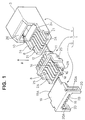
- FIGS. 1 to 5 Next, one embodiment of the invention is described with reference to FIGS. 1 to 5.
- description is not given on a part of the same or similar construction as that of the prior art by identifying it by the same reference numerals.
- a cramping connector 1 is of two-level type, and is comprised of a main block 4 having a hood or receptacle 3, an auxiliary block 5 to be placed substantially on the main block 4 in a direction of height H and a lid 6 for substantially covering an upper part of the auxiliary block 5.
- the main block 4 is integrally or unitarily formed e.g. of a synthetic resin and accommodates terminal fittings 7 (male) substantially inside. Upon the engagement with an unillustrated mating connector housing (female) in a fitting direction F being arranged at an angle different from 0° or 180°, preferably substantially normal to the direction of height H, male and female terminal fittings are connected to establish an electrical connection.
- terminal cavities 2A for accommodating the terminal fittings 7 are substantially open upward and arranged substantially side by side. These terminal cavities 2A belong to the lower level.
- Terminal cavities 2B of the upper level are provided in the auxiliary block 5. More accurately, complete terminal cavities are formed by assembling the main and auxiliary blocks 4, 5.
- the receptacle 3 for the engagement of the mating connector.
- the bottom surface of the main block 4 is substantially planar preferably all the way from the receptacle 3 to the terminal cavities 2A.
- An elastically deformable lance or engaging portion 9 projects forward (i.e. toward the receptacle 3 substantially along the fitting direction F) from the upper wall surface of each terminal cavity 2A.
- the engaging portion 9 is engageable with a corresponding lance hole or engaging hole 18 of the terminal fitting 7.
- the front end of each terminal cavity 2A is substantially open to the receptacle 3, thereby defining a terminal insertion opening 2C.
- the receptacle 3 preferably has a substantially rectangular tubular shape, and an unillustrated mating connector housing is inserted or insertable thereinto.
- a pair of guide grooves 10 extend preferably from a substantially middle position to the substantially rear end of the inner side wall surfaces of the receptacle 3.
- slidable portions 11 of the auxiliary block 5 are slidably fitted or inserted into the guide grooves 10.
- a pressing portion 26 is formed preferably in an upper rear portion of the receptacle 3.
- a lift preventing portion 19A of the lid 6A is positioned radially inward of or below the pressing portion 26.
- the respective terminal cavities 2A are preferably equally partitioned by lower partition walls 8 extending from the rear end of the main block 4 to the receptacle 3. Further, a step wall 24 is formed in a position of the upper edge of each side wall of the main block 4 toward the receptacle 3. A pair of engaging projections 21 for the engagement with the lid 6 to be described later project from the substantially opposite side walls behind the step wall 24.
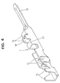
- the terminal fitting 7 is formed e.g. by bending a conductive metal plate.
- a front portion of the terminal fitting 7 serves as the male tab 12 to be engaged with an unillustrated mating female terminal fitting, and stabilizers 15 are formed at the opposite side walls behind the male tab 12 e.g. by raising cut portions to upright positions.
- a hole e.g. left by raising the cut portions to the upright positions is the engaging hole 18 in which the engaging portion 9 is fittable (see FIG. 4).
- the auxiliary block 5 and a press projection 17 of the lid 6 come substantially into contact with the rear end of the bridge 22.
- a pair of blades 13 having preferably a substantially V-shaped cross section are provided one after the other in order to cut the insulation coating of a wire W until the core thereof is reached to establish an electrical connection between the wire W and the terminal fitting 7.
- the blades 13 are formed e.g. by cutting the bottom wall of the terminal fitting 7 and raising the cut portions to positions where they substantially face each other. Projected portions are formed at the opposite ends of each blade 13. The blade 13 provided with the projected portions can be held or positioned in position by being held between the side walls of the terminal fitting 7.
- barrel portions 14 for fastening the wire W project upward from the substantially opposite side walls.
- the auxiliary block 5 is integrally or unitarily formed e.g. of a synthetic resin, accommodates the terminal fittings 7 inside, and is assembled so as to substantially cover the upper openings of the terminal cavities 2A of the main block 4.
- Terminal cavities 2A are also arranged substantially side by side in the auxiliary block 5 and partitioned by the lower partition walls 8 similar to the main block 4.
- upper partition walls 16 project from the bottom surface of the auxiliary block 5, and upper terminal cavities 2B are defined between adjacent upper partition walls 16.
- the upper partition walls 16 substantially come into contact with the upper edges of the lower partition walls 8 to combine the upper and lower terminal cavities 2A, 2B.
- the press projections 17 project forward between two adjacent lower partition walls 8.
- the press projections 17 substantially come into contact with the rear ends of the bridges 22 of the terminal fittings 7 mounted in the main block 4 when the auxiliary block 5 is assembled with the main block 4.
- a pair of slidable portions 11 substantially project at front portions of the opposite side surfaces of the auxiliary block 5.
- the slidable portions 11 are slid substantially into the guide grooves 10 formed in the receptacle 3 of the main block 4 from behind (i.e. from a direction opposed to the tabs 12).
- the press projections 17 press the terminal fittings 7 in the main block 4 to their proper positions as the auxiliary block 5 is mounted.
- each side wall portion 25 is so formed as to be brought substantially into contact with the upper and side surfaces of the corresponding step wall 24 of the main block 4. Further, the rear edges of the side wall portions 25 extend substantially vertically so that the front edges of lock frames 20 of the lid 6 substantially come into contact therewith.
- the lid 6 is integrally or unitarily formed e.g. of a synthetic resin, and is assembled with the auxiliary block 5 and the main block 4 so as to substantially entirely cover the terminal cavities 2A of the auxiliary block 5.
- An upper part of the lid 6 is preferably a substantially rectangular shaped base plate 19, a front portion of which serves as the lift preventing portion 19A for slipping under the pressing portion 26 of the main block 4.
- a pair of lock frames 20 hang from the substantially opposite side surfaces of a rear portion of the base plate 19.
- the lock frames 20 are elastically deformable in directions away from each other.
- a substantially vertically extending groove 20A is formed in a middle portion of each lock frame 20.
- upper partition walls 16 project from the lower surface of the base plate 19 so as to partition the terminal cavities 2A of the auxiliary block 5, and the press projections 17 project forward substantially between two adjacent upper partition walls 16.
- the terminal fittings 7 are inserted into the terminal cavities 2A of the main block 4.
- the wires W are connected to the terminal fittings 7, e.g. by being pressed into the corresponding pairs of blades 13 e.g. using a press jig 23 or the like pressing apparatus of a connecting apparatus (see FIG. 5).
- the blades 13 cut the insulation coatings of the wires W and are brought into contact with the cores of the wires W, thereby establishing an electrical connection between the wires W and the terminal fittings 7.
- the wires W are fastened in the barrel portions 14.
- the bottom surface of the main block 4 is preferably planar as a whole, it is not necessary to provide special recess(es) and projection(s) on a table where the pressing operation is performed.
- the auxiliary block 5 mounted with the terminal fittings 7 is assembled with the main block 4 from behind.
- the auxiliary block 5 is assembled with the main block 4 by sliding the slidable portions 11 formed on the substantially opposite side walls of the auxiliary block 5 into the guide grooves 10 of the receptacle 3.
- the assembling of the blocks 4, 5 is facilitated by being guided by the slidable portions 11 and the guide grooves 10.
- the press projections 17 provided substantially between the upper partition walls 16 of the auxiliary block 5 press the rear ends of the bridges 22 of the terminal fittings 7 mounted in the main block 4.
- the lid 6 is assembled from behind above the auxiliary block 5 by pressing the lift preventing portion 19A of the base plate 19 of the lid 6 so as to be slipped under the pressing portion 26.
- the pressing projections 17 provided on the lower surface of the base plate 19 press the rear end of the bridges 22 of the terminal fittings 7 of the auxiliary block 5.
- the front portions of the lock frames 20 are deformed away from each other in order to move over the engaging projections 21 of the main block 4. Consequently, the engaging projections 21 are fitted into the grooves 20A, completing the assembling of the cramping terminal according to this embodiment.
- the auxiliary block 5 is formed with only the elements necessary to hold the terminal fittings 7, and the receptacle 3 of the main block 4 is shared by the main block 4 and the auxiliary block 5. Accordingly, even if the block for accommodating the terminal fittings 7 is divided into two, the receptacle 3 itself is an integral one having no joining surfaces along vertical direction. Thus, as compared with a sectioned receptacle, rigidity is higher and an excellent shape holding function is ensured. As a result, the male and terminal connectors can be smoothly engaged.
Landscapes
- Connector Housings Or Holding Contact Members (AREA)
- Details Of Connecting Devices For Male And Female Coupling (AREA)
- Connections By Means Of Piercing Elements, Nuts, Or Screws (AREA)
Abstract
Description
- 1
- Cramping Connector
- 2A, 2B
- Terminal Cavity
- 3
- Receptacle
- 4
- Main Block (Connector Housing, Block)
- 5
- Auxiliary Block (Block)
- 7
- Terminal Fitting (Cramping Terminal)
- 10
- Guide Groove (Guide Means)
- 11
- Slidable Portion (Guide Means)
- 12
- Male Tab (Connection Portion)
- 13
- Blade (Cramping Portion)
- 14
- Barrel Portion
- 17
- Press Projection (Correcting Portion)
- W
- Wire
Claims (10)
- A connector (1) in which terminal fittings (7) each provided with a wire connection portion (13) for an electrical connection with a wire (W) and a connection portion (12) to be electrically connected with a mating terminal fitting when a mating connector housing is engaged are accommodated in terminal cavities (2A; 2B) formed in a connector housing (4; 5; 6), wherein:the connector housing (4; 5; 6) comprises at least a main block (4) and an auxiliary block (5) which can be placed substantially one over another in a direction of height (H), andthe main block (4) is formed with a common receptacle (3) which accommodates all terminal fittings (7) when the respective blocks (4; 5) are assembled and is engageable with the mating connector housing.
- A connector according to claim 1, wherein the terminal fittings (7) are cramping terminals (7) and wherein the wire connection portion (13) comprises a cramping portion (13) for cutting the insulation coating of the wire (W) to establish an electrical connection with a core of the wire (W).
- A connector according to one or more of the preceding claims, wherein the terminal cavities (2A; 2B) of the respective blocks (4; 5) are substantially open upward so that the connection portions (12), in particular the pressing or cramping portions (12) of the terminal fittings (7) are to or can be substantially exposed.
- A connector according to one or more of the preceding claims, wherein the main block (4) formed with the receptacle (3) and/or the auxiliary block (5) is provided with a guide means (10; 11) for guiding the assembling of the auxiliary block (5) with the main block (4).
- A connector according to claim 4, wherein the guide means (10; 11) comprises one or more slidable portions (11) and one or more mating guide grooves (10), wherein the slidable portions (11) can be inserted in the guide grooves (10) substantially along a direction (F) of assembling of the blocks (4; 5), the assembling direction (F) being preferably arranged at an angle different from 0° or 180°, preferably substantially normal with respect to the direction of height (H).
- A connector according to one or more of the preceding claims, wherein the one, preferably the upper one (5) of the adjacent blocks (4; 5) to be assembled substantially one over the other is provided with a correcting portion (17) for, when the terminal fittings (7) accommodated in the terminal cavities (2A; 2B) in the other, preferably lower block (4) are insufficiently inserted, pressing the insufficiently inserted terminal fittings (7) to their proper insertion positions (FIG. 3) as the upper block (5) is assembled.
- A connector according to claim 6, wherein the correcting portion (17) interacts with an interaction portion (22) of the terminal fitting (7) substantially along a direction (F) of fitting of the terminal fitting (7) with the mating terminal fitting, the fitting direction (F) being preferably arranged at an angle different from 0° or 180°, preferably substantially normal with respect to the direction of height (H).
- A connector according to claim 7, wherein the interaction portion (22) comprises a bridging portion (22) substantially bridging side wall portions of the terminal fittings (7).
- A connector according to one or more of the preceding claims, wherein the connector housing (4; 5; 6) further comprises an auxiliary housing portion (6), preferably a lid (6), having at least one lock means (20) which are engageable with at least one lock portion (21) provided on the main block (4).
- A connector according to claim 9, wherein the at least one auxiliary block (5) is arranged substantially between the main block (4) and the auxiliary housing portion (6) in the engaged state of the lock means (20) and the lock portion (21).
Applications Claiming Priority (3)
| Application Number | Priority Date | Filing Date | Title |
|---|---|---|---|
| JP00498197A JP3262211B2 (en) | 1997-01-14 | 1997-01-14 | ID connector |
| JP4981/97 | 1997-01-14 | ||
| JP498197 | 1997-01-14 |
Publications (2)
| Publication Number | Publication Date |
|---|---|
| EP0854543A2 true EP0854543A2 (en) | 1998-07-22 |
| EP0854543A3 EP0854543A3 (en) | 2000-02-02 |
Family
ID=11598790
Family Applications (1)
| Application Number | Title | Priority Date | Filing Date |
|---|---|---|---|
| EP98100555A Withdrawn EP0854543A3 (en) | 1997-01-14 | 1998-01-14 | A connector |
Country Status (4)
| Country | Link |
|---|---|
| US (1) | US5957732A (en) |
| EP (1) | EP0854543A3 (en) |
| JP (1) | JP3262211B2 (en) |
| CN (1) | CN1108646C (en) |
Cited By (3)
| Publication number | Priority date | Publication date | Assignee | Title |
|---|---|---|---|---|
| EP1530264A3 (en) * | 2003-11-07 | 2006-02-08 | J.S.T. Mfg. Co., Ltd. | Socket contact |
| EP2445058A1 (en) * | 2010-10-13 | 2012-04-25 | Industrias Lorenzo, SA | Electric connector assembly |
| WO2017009286A1 (en) * | 2015-07-13 | 2017-01-19 | Kostal Kontakt Systeme Gmbh | Multipolar electric plug connector part, and plug connector arrangement |
Families Citing this family (34)
| Publication number | Priority date | Publication date | Assignee | Title |
|---|---|---|---|---|
| JP3330530B2 (en) * | 1997-10-22 | 2002-09-30 | 矢崎総業株式会社 | Coupling connector |
| JPH11273787A (en) * | 1998-03-20 | 1999-10-08 | Yazaki Corp | connector |
| JP3651251B2 (en) * | 1998-04-08 | 2005-05-25 | 住友電装株式会社 | IDC connector |
| JP3651254B2 (en) * | 1998-04-15 | 2005-05-25 | 住友電装株式会社 | connector |
| JP2000048901A (en) * | 1998-07-27 | 2000-02-18 | Yazaki Corp | Waterproof connector |
| TW404584U (en) * | 1998-11-24 | 2000-09-01 | Hon Hai Prec Ind Co Ltd | Electrical connector |
| JP3618569B2 (en) * | 1999-03-01 | 2005-02-09 | 矢崎総業株式会社 | Combined connector |
| JP3696455B2 (en) * | 1999-10-08 | 2005-09-21 | 矢崎総業株式会社 | Waterproof connector |
| US6217374B1 (en) * | 1999-11-18 | 2001-04-17 | Molex Incorporated | Electrical connector with wire management system |
| TW453532U (en) * | 2000-09-29 | 2001-09-01 | Molex Inc | Cable connector structure |
| JP2002343503A (en) * | 2001-05-17 | 2002-11-29 | Yazaki Corp | Multi-pole connector |
| JP3883399B2 (en) * | 2001-07-04 | 2007-02-21 | 矢崎総業株式会社 | connector |
| US6764350B2 (en) | 2002-04-23 | 2004-07-20 | Itt Manufacturing Enterprises, Inc. | Connector contact retention |
| JP4299079B2 (en) * | 2003-09-05 | 2009-07-22 | 矢崎総業株式会社 | Assembly structure of cassette relay block |
| JP4168906B2 (en) * | 2003-10-29 | 2008-10-22 | 住友電装株式会社 | Split connector |
| CN2674695Y (en) * | 2003-12-06 | 2005-01-26 | 富士康(昆山)电脑接插件有限公司 | Electronic card connector |
| US20090221190A1 (en) * | 2005-06-06 | 2009-09-03 | Mitsubishi Cable Industries, Ltd. | Electric connector housing |
| CN200972950Y (en) * | 2006-10-09 | 2007-11-07 | 富士康(昆山)电脑接插件有限公司 | Electric connector |
| JP2010146820A (en) * | 2008-12-18 | 2010-07-01 | Sumitomo Wiring Syst Ltd | Terminal insertion state inspection device |
| US7833068B2 (en) * | 2009-01-14 | 2010-11-16 | Tyco Electronics Corporation | Receptacle connector for a transceiver assembly |
| JP2013137922A (en) * | 2011-12-28 | 2013-07-11 | Tyco Electronics Japan Kk | Electric connector |
| CN103682716A (en) * | 2012-09-17 | 2014-03-26 | 凡甲电子(苏州)有限公司 | Cable connector |
| CN103208695A (en) * | 2013-03-14 | 2013-07-17 | 广州市增城和运五金加工厂 | Mini-type electric connector |
| DE202013006297U1 (en) * | 2013-07-11 | 2013-07-25 | Rosenberger Hochfrequenztechnik Gmbh & Co. Kg | Connectors |
| CN104425946B (en) * | 2013-09-06 | 2017-08-25 | 富士康(昆山)电脑接插件有限公司 | Electric connector |
| JP6195165B2 (en) * | 2014-03-13 | 2017-09-13 | 住友電装株式会社 | connector |
| US9647378B1 (en) * | 2016-05-10 | 2017-05-09 | Te Connectivity Corporation | Electrical connector |
| CN107681290B (en) * | 2016-08-02 | 2020-10-16 | 东莞莫仕连接器有限公司 | Cable assembly with improved cable retention |
| JP6812917B2 (en) * | 2017-07-11 | 2021-01-13 | 株式会社オートネットワーク技術研究所 | Terminal bracket |
| US10418734B1 (en) * | 2018-07-26 | 2019-09-17 | Te Connectivity Corporation | Contact assembly for a straddle mount connector |
| US20220109263A1 (en) * | 2019-02-15 | 2022-04-07 | Hirschmann Automotive Gmbh | Plug connector with high-voltage flashover protection |
| USD1055863S1 (en) * | 2022-09-22 | 2024-12-31 | Ningbo Jintianlang Technology Co., Ltd. | Trailer wiring connector |
| USD1047917S1 (en) * | 2022-10-17 | 2024-10-22 | Telebox Industries Corp. | Connector body |
| USD1054384S1 (en) * | 2022-10-27 | 2024-12-17 | Telebox Industries Corp. | Connector body |
Family Cites Families (6)
| Publication number | Priority date | Publication date | Assignee | Title |
|---|---|---|---|---|
| DE3526664C2 (en) * | 1984-08-06 | 1995-02-16 | Amp Inc | Electrical connector |
| BE900692A (en) * | 1984-09-27 | 1985-03-27 | Burndy Electra Nv | CONNECTOR FOR INDIVIDUAL CONDUCTORS AND METHOD FOR WIRING SUCH CONNECTOR. |
| JPH02223171A (en) * | 1988-11-24 | 1990-09-05 | Yazaki Corp | Multi-stage connector and electric wire pressure-welding method |
| DE3938964A1 (en) * | 1988-11-24 | 1990-05-31 | Yazaki Corp | MULTIPLE LEVEL CONNECTOR |
| JP2671729B2 (en) * | 1992-09-29 | 1997-10-29 | 住友電装株式会社 | Connector device |
| JP2863095B2 (en) * | 1994-08-17 | 1999-03-03 | 矢崎総業株式会社 | ID connector |
-
1997
- 1997-01-14 JP JP00498197A patent/JP3262211B2/en not_active Expired - Fee Related
- 1997-12-30 US US09/000,700 patent/US5957732A/en not_active Expired - Fee Related
-
1998
- 1998-01-14 CN CN98103973.1A patent/CN1108646C/en not_active Expired - Fee Related
- 1998-01-14 EP EP98100555A patent/EP0854543A3/en not_active Withdrawn
Cited By (4)
| Publication number | Priority date | Publication date | Assignee | Title |
|---|---|---|---|---|
| EP1530264A3 (en) * | 2003-11-07 | 2006-02-08 | J.S.T. Mfg. Co., Ltd. | Socket contact |
| EP2445058A1 (en) * | 2010-10-13 | 2012-04-25 | Industrias Lorenzo, SA | Electric connector assembly |
| WO2017009286A1 (en) * | 2015-07-13 | 2017-01-19 | Kostal Kontakt Systeme Gmbh | Multipolar electric plug connector part, and plug connector arrangement |
| US10050381B2 (en) | 2015-07-13 | 2018-08-14 | Kostal Kontakt Systeme Gmbh | Plug connector having housing parts having channels with spring tongues for fixing plug contacts within the channels |
Also Published As
| Publication number | Publication date |
|---|---|
| JP3262211B2 (en) | 2002-03-04 |
| JPH10199607A (en) | 1998-07-31 |
| CN1188336A (en) | 1998-07-22 |
| US5957732A (en) | 1999-09-28 |
| EP0854543A3 (en) | 2000-02-02 |
| CN1108646C (en) | 2003-05-14 |
Similar Documents
| Publication | Publication Date | Title |
|---|---|---|
| US5957732A (en) | Connector | |
| US6692294B2 (en) | Connector | |
| US5542851A (en) | Electrical connector with improved grounding | |
| US20090047840A1 (en) | Power connector with sealed inner base member | |
| US6129574A (en) | Connector having a construction for preventing an erroneous assembling of a connector housing and a cover | |
| US8087945B2 (en) | Electric connector with a dust cover | |
| EP0986146A1 (en) | Connector and method of attaching a terminal fitting therein to a cable | |
| US6402568B1 (en) | Combined-type connector | |
| US6416349B1 (en) | IDC connector | |
| US6358098B1 (en) | Terminal and a joint connector | |
| EP1134848B1 (en) | A connector and a set of terminal fittings | |
| JPH1074542A (en) | ID connector | |
| US7090543B2 (en) | Wire harness connector | |
| US6231400B1 (en) | Combined-type connector | |
| JP2916567B2 (en) | Joint connector | |
| JP3174276B2 (en) | Housing for crimping connector and method of assembling the same | |
| JP2000294334A (en) | Connector rattling prevention structure | |
| US6780063B2 (en) | Wire connected modular jack and assembling method | |
| US7371127B2 (en) | Modular jack | |
| JP2002056917A (en) | Joint connector | |
| JPH065147U (en) | connector | |
| JPH02306559A (en) | Female terminal for electric connector | |
| JP7725152B2 (en) | connector | |
| GB2162702A (en) | Latching electrical contact into connector body | |
| JPH0690510A (en) | Distribution unit and electric connector |
Legal Events
| Date | Code | Title | Description |
|---|---|---|---|
| PUAI | Public reference made under article 153(3) epc to a published international application that has entered the european phase |
Free format text: ORIGINAL CODE: 0009012 |
|
| 17P | Request for examination filed |
Effective date: 19980206 |
|
| AK | Designated contracting states |
Kind code of ref document: A2 Designated state(s): DE FR GB IT |
|
| AX | Request for extension of the european patent |
Free format text: AL;LT;LV;MK;RO;SI |
|
| PUAL | Search report despatched |
Free format text: ORIGINAL CODE: 0009013 |
|
| AK | Designated contracting states |
Kind code of ref document: A3 Designated state(s): AT BE CH DE DK ES FI FR GB GR IE IT LI LU MC NL PT SE |
|
| AX | Request for extension of the european patent |
Free format text: AL;LT;LV;MK;RO;SI |
|
| AKX | Designation fees paid |
Free format text: DE FR GB IT |
|
| STAA | Information on the status of an ep patent application or granted ep patent |
Free format text: STATUS: THE APPLICATION HAS BEEN WITHDRAWN |
|
| 18W | Application withdrawn |
Withdrawal date: 20011221 |