EP0853326B1 - Electric circuit breaker with means for adjusting the contacts - Google Patents
Electric circuit breaker with means for adjusting the contacts Download PDFInfo
- Publication number
- EP0853326B1 EP0853326B1 EP97203973A EP97203973A EP0853326B1 EP 0853326 B1 EP0853326 B1 EP 0853326B1 EP 97203973 A EP97203973 A EP 97203973A EP 97203973 A EP97203973 A EP 97203973A EP 0853326 B1 EP0853326 B1 EP 0853326B1
- Authority
- EP
- European Patent Office
- Prior art keywords
- contacts
- circuit breaker
- screw
- arc
- operating shaft
- Prior art date
- Legal status (The legal status is an assumption and is not a legal conclusion. Google has not performed a legal analysis and makes no representation as to the accuracy of the status listed.)
- Expired - Lifetime
Links
Images


Classifications
-
- H—ELECTRICITY
- H01—ELECTRIC ELEMENTS
- H01H—ELECTRIC SWITCHES; RELAYS; SELECTORS; EMERGENCY PROTECTIVE DEVICES
- H01H69/00—Apparatus or processes for the manufacture of emergency protective devices
- H01H69/01—Apparatus or processes for the manufacture of emergency protective devices for calibrating or setting of devices to function under predetermined conditions
-
- H—ELECTRICITY
- H01—ELECTRIC ELEMENTS
- H01H—ELECTRIC SWITCHES; RELAYS; SELECTORS; EMERGENCY PROTECTIVE DEVICES
- H01H1/00—Contacts
- H01H1/12—Contacts characterised by the manner in which co-operating contacts engage
- H01H1/14—Contacts characterised by the manner in which co-operating contacts engage by abutting
- H01H1/34—Contacts characterised by the manner in which co-operating contacts engage by abutting with provision for adjusting position of contact relative to its co-operating contact
-
- H—ELECTRICITY
- H01—ELECTRIC ELEMENTS
- H01H—ELECTRIC SWITCHES; RELAYS; SELECTORS; EMERGENCY PROTECTIVE DEVICES
- H01H1/00—Contacts
- H01H1/12—Contacts characterised by the manner in which co-operating contacts engage
- H01H1/14—Contacts characterised by the manner in which co-operating contacts engage by abutting
- H01H1/22—Contacts characterised by the manner in which co-operating contacts engage by abutting with rigid pivoted member carrying the moving contact
- H01H1/221—Contacts characterised by the manner in which co-operating contacts engage by abutting with rigid pivoted member carrying the moving contact and a contact pressure spring acting between the pivoted member and a supporting member
- H01H1/226—Contacts characterised by the manner in which co-operating contacts engage by abutting with rigid pivoted member carrying the moving contact and a contact pressure spring acting between the pivoted member and a supporting member having a plurality of parallel contact bars
-
- H—ELECTRICITY
- H01—ELECTRIC ELEMENTS
- H01H—ELECTRIC SWITCHES; RELAYS; SELECTORS; EMERGENCY PROTECTIVE DEVICES
- H01H3/00—Mechanisms for operating contacts
- H01H3/32—Driving mechanisms, i.e. for transmitting driving force to the contacts
- H01H2003/323—Driving mechanisms, i.e. for transmitting driving force to the contacts the mechanisms being adjustable
-
- H—ELECTRICITY
- H01—ELECTRIC ELEMENTS
- H01H—ELECTRIC SWITCHES; RELAYS; SELECTORS; EMERGENCY PROTECTIVE DEVICES
- H01H73/00—Protective overload circuit-breaking switches in which excess current opens the contacts by automatic release of mechanical energy stored by previous operation of a hand reset mechanism
- H01H73/02—Details
- H01H73/04—Contacts
Definitions
- the invention relates to an electric circuit breaker with means for adjusting the contacts, comprising for each electric phase moving levers having main contacts and arc-breaking contacts co-operating with main contacts and arc-breaking contacts provided on a terminal bar.
- An electric circuit breaker, according to the preamble of claim 1 is known from US-A-5 519 180.
- the electric contacts require a small resistivity.
- the requirement demanded of the electric contacts is a high resistance to the electric arc generated during the interruption of an overcurrent or short-circuit and hence high resistivity.
- the function of carrying the rated current is accomplished by the first contacts or main contacts, made from softer material.
- the function of interrupting the overload or short-circuit current is accomplished by second contacts or arc-breaking contacts, made from tougher materials.
- Metal inserts constituting the main contacts and moving arc-breaking contacts, are inserted at various heights on moving levers supported by cranks pivoting on the box of the circuit breaker.
- a known linkage generates, during the opening phase, the movement of the contact-carrying levers which effects the switchover from the main contacts to the arc-breaking contacts.
- To obtain correct operation of the circuit breaker it is necessary for the switchover from the main to the arc-breaking contacts to take place in accordance with an accurate time sequence.
- the desired accuracy in the time sequence is obtained by adjustment of the distance of the corresponding fixed and moving contacts.
- this adjustment is performed by rotating the moving contact-carrying levers, by virtue of a known adjustment device, acting on each contact-carrying lever.
- the objective of the present invention is to overcome the drawbacks of the prior art and to allow the simultaneous adjustment of all the contacts of the circuit breaker by a few simple operations.
- an electric circuit breaker with means for adjusting the contacts comprising for each electric phase moving levers having main contacts and arc-breaking contacts co-operating with main contacts and arc-breaking contacts provided on a terminal bar, characterized in that a pin receives a pivoting crank, in that the levers of the contacts, loaded by springs, are fulcrumed to the crank, in that the crank is operationally connected to a link-rod articularly joined to an operating shaft and in that each end of the operating shaft is supported by translatable adjustment supports.
- a simple constructional realization of the invention can consist in the fact that the supports are made as slides running in slots, made in the abutments of the box of the circuit breaker, and in that they have means for adjusting the position of the slide.
- the slide exhibits laterally a seat for a head of a screw, the screw is inserted into a threaded hole present on a projection made laterally to the slot and the screw is locked by a nut.
- the seat made on the slide, has its inner surfaces in contact with the upper and lower faces of the head of the adjusting screw.
- the slides have housings for the pins of the operating shaft which are made of self-lubricating material.
- the advantages of the present invention may be summarized mainly in the simplified and easier operation of simultaneous adjustment of the contacts of the circuit breaker.
- An advantage lies moreover in the reduction in the components required for the adjustment of the contacts and a consequent simplification and reduction in the phases of assembling the circuit breaker.
- An operating shaft 1 is connected by means of an insulating link-rod 2 to a crank 3 constituting the support for levers having moving contacts, which are indicated 4 as a whole.
- the crank 3 can pivot about a pin 12, which is integral with the abutments 21 of the circuit breaker.
- the moveable contacts 4 are made, for example, by means of eight levers, or fingers 5, each carrying a main contact 6 and an arc-breaking contact 7.
- the fixed main contacts 9 and the fixed arc-breaking contacts 10 are supported by an upper terminal bar 11 which is used for the electrical connection of the circuit breaker to the electrical installation.
- the operating shaft 1 transmits a movement imposed by a control, not illustrated, simultaneously to the three or four phases of the circuit breaker. Only one phase is depicted in the figures.
- the ends of the operating shaft 1 are connected, by means of a support indicated 20 as a whole, to the abutments 21 of the box of the circuit breaker.
- the operating shaft 1 has a pin, in this case the end pin 22, inserted into a circular seat of a slide 23.
- the circular seat is made from a self-lubricating material so as to reduce the friction between pin 22 and the circular seat during the rotation of the operating shaft 1.
- the slide 23 exhibits laterally a cylindrical extension 24 constituting the prolongation of the circular seat of the pin 22.
- the cylindrical extension 24 is inserted into a slot 25 made in the abutment 21 of the box. Which slot constitutes a guide in which the cylindrical extension 24 of the slide 23 can run.
- the slide 23 has a seat 26 for the head 27 of a screw 28.
- the seat 26 made in the slide 23 hugs the head 27 of the screw 28, disallowing any axial movement of the screw relative to the slide.
- the surfaces of the seat 26 are in contact with the upper and lower faces of the head 27 of the screw 28.
- a projection 30 is fixed to the flank 21 in front of the slot 25 so as to constitute a stop for the slide 23.
- the shank of the screw 28 is screwed into a threaded hole present in the projection 30 and protrudes from the opposite part of the projection 30.
- a nut 31 is screwed onto the shank of the screw 28, protruding from the projection 30.
- the operating shaft 1 controls via the insulating link-rod 2 the rotation (in the direction of the arrows A and B) about the pin 12 of the moving contact-carrying crank 3.
- the operating shaft 1 is mounted on the slides 23 translating inside the slots 25 made in the abutments or in the central ribs of the box of the circuit breaker.
- By loosening the nut 31 it is possible to rotate the screw 28 and displace, inside the slot 25, the slide 23 supporting the operating shaft 1 towards the front (F) of the circuit breaker or towards the rear (R) of the circuit breaker, thereby obtaining a rotation of the moving contact-carrying crank 3 with respect to the crank pin 12, respectively clockwise (in the direction of the arrow B) or anticlockwise (in the direction of the arrow A).
- the fingers 5 rotate, respectively increasing or decreasing the distance (D) between the fixed 10 and moveable 7 arc-breaking contacts of the circuit breaker.
- the distance between the arc-breaking contacts 10,7 is thus a design datum which defines the time sequence for switching the current from the main contacts 9,6 to the arc-breaking contacts 10,7 so as to safeguard the main contacts 9,6, made from soft material, from wear caused by the extinction of the electric arc during the circuit breaker opening operations.
- the tightening of the nut 31 ensures that the adjustment performed is guaranteed to be unimpaired throughout the working of the circuit breaker.
Landscapes
- Engineering & Computer Science (AREA)
- Manufacturing & Machinery (AREA)
- Breakers (AREA)
- Arc-Extinguishing Devices That Are Switches (AREA)
- Percussion Or Vibration Massage (AREA)
- Push-Button Switches (AREA)
- Cookers (AREA)
Description
- The invention relates to an electric circuit breaker with means for adjusting the contacts, comprising for each electric phase moving levers having main contacts and arc-breaking contacts co-operating with main contacts and arc-breaking contacts provided on a terminal bar. An electric circuit breaker, according to the preamble of
claim 1 is known from US-A-5 519 180. - It is known from the prior art that industrial low-voltage circuit breakers accomplish two tasks in the main: allowing the flow of a rated current and interrupting higher overload or short-circuit currents. These two tasks, investigated from the point of view of the electric contacts, are mutually conflicting.
- Thus, in order to guarantee low consumption and a low working temperature during the flow of the rated current, the electric contacts require a small resistivity. On the other hand, for the purpose of interrupting overcurrents, the requirement demanded of the electric contacts is a high resistance to the electric arc generated during the interruption of an overcurrent or short-circuit and hence high resistivity.
- Being impossible to satisfy with the same material the requirement of low resistivity and high thermal resistance simultaneously the tasks of transmitting the rated current and of interrupting overcurrents are accomplished by two distinct contacts made from different materials.
- The function of carrying the rated current is accomplished by the first contacts or main contacts, made from softer material. The function of interrupting the overload or short-circuit current is accomplished by second contacts or arc-breaking contacts, made from tougher materials.
- Metal inserts, constituting the main contacts and moving arc-breaking contacts, are inserted at various heights on moving levers supported by cranks pivoting on the box of the circuit breaker. Corresponding metal inserts, constituting the main contacts and the fixed arc-breaking contacts, are inserted on the end of upper terminal bars of the circuit breaker.
- A known linkage generates, during the opening phase, the movement of the contact-carrying levers which effects the switchover from the main contacts to the arc-breaking contacts. To obtain correct operation of the circuit breaker it is necessary for the switchover from the main to the arc-breaking contacts to take place in accordance with an accurate time sequence. The desired accuracy in the time sequence is obtained by adjustment of the distance of the corresponding fixed and moving contacts.
- At the present time, this adjustment is performed by rotating the moving contact-carrying levers, by virtue of a known adjustment device, acting on each contact-carrying lever.
- The operation of adjusting the position of the individual contacts of the complete circuit breaker is made extremely arduous and lengthy due to the presence inside the circuit breakers of three or four electric phases, each made with several contact-carrying levers, for example eight levers, each having a main contact and an arc-breaking contact.
- These operations are usually carried out by specialist staff using for example suitable feeler gauges inserted between the corresponding fixed and moving arc-breaking contacts, when the circuit breaker is closed and therefore when the main contacts are shut. The adjustment operation is performed by rotating the individual contact-carrying lever until the feeler gauge is clamped between the arc-breaking contacts with the desired force.
- As may easily be appreciated, this operation requires a certain accuracy in its performance and hence, given also the considerable number of contacts present in the circuit breaker, makes this phase of the manufacture of the circuit breaker extremely lengthy.
- The objective of the present invention is to overcome the drawbacks of the prior art and to allow the simultaneous adjustment of all the contacts of the circuit breaker by a few simple operations.
- The objectives of the invention are achieved by means of an electric circuit breaker with means for adjusting the contacts, comprising for each electric phase moving levers having main contacts and arc-breaking contacts co-operating with main contacts and arc-breaking contacts provided on a terminal bar, characterized in that a pin receives a pivoting crank, in that the levers of the contacts, loaded by springs, are fulcrumed to the crank, in that the crank is operationally connected to a link-rod articularly joined to an operating shaft and in that each end of the operating shaft is supported by translatable adjustment supports.
- A simple constructional realization of the invention can consist in the fact that the supports are made as slides running in slots, made in the abutments of the box of the circuit breaker, and in that they have means for adjusting the position of the slide.
- Advantageously the slide exhibits laterally a seat for a head of a screw, the screw is inserted into a threaded hole present on a projection made laterally to the slot and the screw is locked by a nut.
- To obtain accurate and hence play-free adjustment, the seat, made on the slide, has its inner surfaces in contact with the upper and lower faces of the head of the adjusting screw. To ease the closing and opening movement of the circuit breaker the slides have housings for the pins of the operating shaft which are made of self-lubricating material.
- The advantages of the present invention may be summarized mainly in the simplified and easier operation of simultaneous adjustment of the contacts of the circuit breaker.
- An advantage lies moreover in the reduction in the components required for the adjustment of the contacts and a consequent simplification and reduction in the phases of assembling the circuit breaker.
- The subject, devised according to the present invention, will be described below in greater detail and illustrated in an embodiment given, merely by way of example, in the appended drawings in which:
- Figure 1 illustrates, in partially sectioned axonometric view, the mechanism for operating the contacts of an electric phase of a circuit breaker;
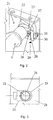
- Figure 2 illustrates, in partially sectioned axonometric view, a support for adjusting the operating shaft;
- Figure 3 illustrates the support of the operating shaft viewed in the direction of the arrow X of Figure 2;
- Figure 4 illustrates, diagrammatically in a side view in partial cross-section, the mechanism according to Figure 1.
-
- The manner of construction and operation of the electric circuit breaker are essentially known, so that details of only the parts which are novel and essential to the invention will be provided below.
- From the figures it is possible to observe some of the components constituting one of the phases of a circuit breaker, which is illustrated in the closed position.
- An
operating shaft 1 is connected by means of an insulating link-rod 2 to acrank 3 constituting the support for levers having moving contacts, which are indicated 4 as a whole. - The
crank 3 can pivot about apin 12, which is integral with theabutments 21 of the circuit breaker. - The moveable contacts 4 are made, for example, by means of eight levers, or
fingers 5, each carrying amain contact 6 and an arc-breakingcontact 7. The fixed contacts, indicated 8 as a whole, face themoveable contacts main contacts 9 and the fixed arc-breakingcontacts 10 are supported by anupper terminal bar 11 which is used for the electrical connection of the circuit breaker to the electrical installation. - Springs 13 push the
levers 5 carrying the moveablemain contacts 6 against the fixedmain contacts 9 with a force necessary to have an area of contact wide enough to guarantee low electrical resistance and additionally preload the linkage consisting of thecrank 3, the link-rod 2 and theoperating shaft 1. - The
operating shaft 1 transmits a movement imposed by a control, not illustrated, simultaneously to the three or four phases of the circuit breaker. Only one phase is depicted in the figures. The ends of theoperating shaft 1 are connected, by means of a support indicated 20 as a whole, to theabutments 21 of the box of the circuit breaker. - From Figures 2 and 3 it is possible to observe the main components which make up the
adjustable support 20. - The
operating shaft 1 has a pin, in this case theend pin 22, inserted into a circular seat of aslide 23. - Advantageously the circular seat is made from a self-lubricating material so as to reduce the friction between
pin 22 and the circular seat during the rotation of theoperating shaft 1. - The
slide 23 exhibits laterally acylindrical extension 24 constituting the prolongation of the circular seat of thepin 22. Thecylindrical extension 24 is inserted into aslot 25 made in theabutment 21 of the box. Which slot constitutes a guide in which thecylindrical extension 24 of theslide 23 can run. - At the front the
slide 23 has aseat 26 for thehead 27 of ascrew 28. Theseat 26 made in theslide 23 hugs thehead 27 of thescrew 28, disallowing any axial movement of the screw relative to the slide. In particular, the surfaces of theseat 26 are in contact with the upper and lower faces of thehead 27 of thescrew 28. - A
projection 30 is fixed to theflank 21 in front of theslot 25 so as to constitute a stop for theslide 23. - The shank of the
screw 28 is screwed into a threaded hole present in theprojection 30 and protrudes from the opposite part of theprojection 30. Anut 31 is screwed onto the shank of thescrew 28, protruding from theprojection 30. - The operation of the device which is the subject of the invention may be observed from Figure 4.
- The
operating shaft 1 controls via the insulating link-rod 2 the rotation (in the direction of the arrows A and B) about thepin 12 of the moving contact-carryingcrank 3. - The
operating shaft 1 is mounted on theslides 23 translating inside theslots 25 made in the abutments or in the central ribs of the box of the circuit breaker. By loosening thenut 31 it is possible to rotate thescrew 28 and displace, inside theslot 25, theslide 23 supporting theoperating shaft 1 towards the front (F) of the circuit breaker or towards the rear (R) of the circuit breaker, thereby obtaining a rotation of the moving contact-carryingcrank 3 with respect to thecrank pin 12, respectively clockwise (in the direction of the arrow B) or anticlockwise (in the direction of the arrow A). - Through the fulcrum effect which is generated at the point of opposition between the fixed 9 and moveable 6 main contacts, on account of the displacement of the
slide 23 towards the front (F) or the rear (R) of the circuit breaker, thefingers 5 rotate, respectively increasing or decreasing the distance (D) between the fixed 10 and moveable 7 arc-breaking contacts of the circuit breaker. - The distance between the arc-
breaking contacts main contacts breaking contacts main contacts - The tightening of the
nut 31 ensures that the adjustment performed is guaranteed to be unimpaired throughout the working of the circuit breaker. - Simultaneous adjustment of the distances between all the arc-breaking
contacts supports 20 of theoperating shaft 1, presupposes precise alignment of thefingers 5 carrying themoving contacts
Claims (5)
- Electric circuit breaker with means for adjusting the contacts (4), comprising for each electric phase moving levers (5) having main contacts (6) and arc-breaking contacts (7) co-operating with main contacts (9) and arc-breaking contacts (10) provided on a terminal bar (11), characterized in that a pin (12) receives a pivoting crank (3), in that the levers (5) of the contacts, loaded by springs (13), are fulcrumed to the crank (3), in that the crank (3) is operationally connected to a link-rod (2) articularly joined to an operating shaft (1) and in that each end of the operating shaft (1) is supported by translatable adjustment supports.
- Circuit breaker, according to Claim 1, characterized in that the supports (20) are made as slides (23) running in slots (25), made in the abutments (21) of the box of the circuit breaker, and in that they have means for adjusting the position of the slides (23).
- Circuit breaker, according to Claim 2, characterized in that the slide (23) exhibits laterally a seat (26) for a head (27) of a screw (28), in that the screw (28) is inserted into a threaded hole present on a projection (30) made laterally to the slot (25) and in that the screw (28) is locked by a nut (31).
- Circuit breaker, according to Claim 3, characterized in that the seat (26) present on the slide (23) has its inner surfaces in contact with the upper and lower faces of the head (27) of the screw (28).
- Circuit breaker, according to Claim 2, characterized in that the slides (23) have housings for the pins (22) of the operating shaft (1) which are made of self-lubricating material.
Applications Claiming Priority (2)
| Application Number | Priority Date | Filing Date | Title |
|---|---|---|---|
| ITMI962688 | 1996-12-20 | ||
| IT96MI002688A IT1289483B1 (en) | 1996-12-20 | 1996-12-20 | ELECTRIC SWITCH WITH MEANS FOR THE REGULATION OF THE CONTACTS |
Publications (3)
| Publication Number | Publication Date |
|---|---|
| EP0853326A2 EP0853326A2 (en) | 1998-07-15 |
| EP0853326A3 EP0853326A3 (en) | 1999-03-17 |
| EP0853326B1 true EP0853326B1 (en) | 2003-10-22 |
Family
ID=11375448
Family Applications (1)
| Application Number | Title | Priority Date | Filing Date |
|---|---|---|---|
| EP97203973A Expired - Lifetime EP0853326B1 (en) | 1996-12-20 | 1997-12-17 | Electric circuit breaker with means for adjusting the contacts |
Country Status (6)
| Country | Link |
|---|---|
| US (1) | US6023035A (en) |
| EP (1) | EP0853326B1 (en) |
| CN (1) | CN1066566C (en) |
| DE (1) | DE69725693T2 (en) |
| ES (1) | ES2210453T3 (en) |
| IT (1) | IT1289483B1 (en) |
Cited By (1)
| Publication number | Priority date | Publication date | Assignee | Title |
|---|---|---|---|---|
| EP4285398A4 (en) * | 2021-01-28 | 2024-10-30 | Abb Schweiz Ag | Adjusting mechanism of circuit breaker and corresponding circuit breaker |
Families Citing this family (14)
| Publication number | Priority date | Publication date | Assignee | Title |
|---|---|---|---|---|
| IT1314039B1 (en) * | 1999-10-08 | 2002-12-03 | Abb Ricerca Spa | ELECTRIC POLE FOR LOW VOLTAGE POWER SWITCH. |
| DE10007401A1 (en) * | 2000-02-11 | 2001-08-16 | Siemens Ag | Length-adjustable arrangement for connection as a coupling element in circuit breakers |
| DE10044060C1 (en) * | 2000-08-31 | 2002-05-16 | Siemens Ag | Contact device for electric switch has contact carrier provided with eccentric shaft acting as a contact force adjustment element |
| DE10117844A1 (en) | 2001-04-04 | 2002-10-17 | Siemens Ag | Circuit arrangement for low voltage circuit breakers |
| DE10137422C1 (en) * | 2001-07-27 | 2002-11-14 | Siemens Ag | Contact carrier for LV switchgear has coupling lever between drive shaft and contact carrier body attached to latter in adjustable position for altering switching force |
| DE10261853B3 (en) * | 2002-12-20 | 2004-04-22 | Siemens Ag | Multi-pole power switch for 3-phase load, has feedback torque exerted on switch shaft by one switch pole reduced relative to feedback torque exerted on switch shaft by further switch pole |
| DE10323094B3 (en) | 2003-05-16 | 2004-08-12 | Siemens Ag | Electrical power switch has switch shaft supported by bearings provided by one housing shell with fixings between housing shells provided by shaft bearing and second housing shell |
| DE102005022230A1 (en) * | 2005-05-10 | 2006-11-16 | Siemens Ag | Drive train for coupling a moving contact to a drive and low-voltage circuit breaker with a drive train |
| KR101078974B1 (en) * | 2010-01-13 | 2011-11-01 | 엘에스산전 주식회사 | Driving mechanism for 4 poles circuit breaker |
| EP2416332A1 (en) * | 2010-08-06 | 2012-02-08 | Eaton Industries GmbH | Switching device for an electric low voltage switching device |
| FR2980624B1 (en) * | 2011-09-23 | 2014-05-16 | Schneider Electric Ind Sas | ELECTRICAL PROTECTION APPARATUS HAVING A ROLLER SUPPORTING A MOBILE CONTACT |
| CN102931037A (en) * | 2012-09-10 | 2013-02-13 | 江苏镇安电力设备有限公司 | Device for adjusting contact surface of moving contact and fixed contact of direct current high-speed circuit breaker |
| CN107680891B (en) * | 2017-10-31 | 2020-06-30 | 首瑞(天津)电气设备有限公司 | Contact arc extinguishing system, low-voltage circuit breaker and arc extinguishing system |
| CN109449051B (en) * | 2018-10-22 | 2020-06-30 | 安徽银点电子科技有限公司 | Drum-type multi-contact relay |
Family Cites Families (5)
| Publication number | Priority date | Publication date | Assignee | Title |
|---|---|---|---|---|
| NL46947C (en) * | 1935-08-21 | |||
| US4551597A (en) * | 1983-12-19 | 1985-11-05 | Westinghouse Electric Corp. | Molded case circuit breaker with adjustable stationary lower electrical contact |
| US4616202A (en) * | 1984-11-20 | 1986-10-07 | Mitsubishi Denki Kabushiki Kaisha | Electromagnetic contactor |
| US5359161A (en) * | 1993-01-08 | 1994-10-25 | Square D Company | Non-linear spring for circuit interrupters |
| US5519180A (en) * | 1994-08-08 | 1996-05-21 | General Electric Company | Method for controlling contact depression for high ampere-rated circuit |
-
1996
- 1996-12-20 IT IT96MI002688A patent/IT1289483B1/en active IP Right Grant
-
1997
- 1997-12-17 ES ES97203973T patent/ES2210453T3/en not_active Expired - Lifetime
- 1997-12-17 DE DE69725693T patent/DE69725693T2/en not_active Expired - Lifetime
- 1997-12-17 EP EP97203973A patent/EP0853326B1/en not_active Expired - Lifetime
- 1997-12-18 US US08/993,040 patent/US6023035A/en not_active Expired - Lifetime
- 1997-12-22 CN CN97125953A patent/CN1066566C/en not_active Expired - Lifetime
Cited By (1)
| Publication number | Priority date | Publication date | Assignee | Title |
|---|---|---|---|---|
| EP4285398A4 (en) * | 2021-01-28 | 2024-10-30 | Abb Schweiz Ag | Adjusting mechanism of circuit breaker and corresponding circuit breaker |
Also Published As
| Publication number | Publication date |
|---|---|
| CN1066566C (en) | 2001-05-30 |
| EP0853326A2 (en) | 1998-07-15 |
| CN1185645A (en) | 1998-06-24 |
| ES2210453T3 (en) | 2004-07-01 |
| EP0853326A3 (en) | 1999-03-17 |
| ITMI962688A1 (en) | 1998-06-20 |
| IT1289483B1 (en) | 1998-10-15 |
| HK1011237A1 (en) | 1999-07-09 |
| DE69725693D1 (en) | 2003-11-27 |
| DE69725693T2 (en) | 2004-08-05 |
| US6023035A (en) | 2000-02-08 |
Similar Documents
| Publication | Publication Date | Title |
|---|---|---|
| US6023035A (en) | Electric circuit breaker with means for adjusting the contacts | |
| US4691182A (en) | Circuit breaker with adjustable magnetic trip unit | |
| KR970007774B1 (en) | Circuit breaker with adjustable thermal trip unit | |
| AU639713B2 (en) | Circuit breaker with adjustable low magnetic trip | |
| CA2010695A1 (en) | Circuit breaker with individual gap adjustment at high and low settings of magnetic trip | |
| US7009129B2 (en) | Switching device comprising a breaker mechanism | |
| EP1109189B1 (en) | Circuit breaker rotary contact arm arrangement | |
| US6396369B1 (en) | Rotary contact assembly for high ampere-rated circuit breakers | |
| US5471184A (en) | Circuit breaker | |
| CN112005327B (en) | Low voltage circuit breaker | |
| US3944959A (en) | Electrical circuit breaker | |
| US4030060A (en) | Thermally adjustable circuit breaker | |
| EP0797834A1 (en) | Interface connection for a circuit breaker plug-in trip unit | |
| US4704593A (en) | Circuit breaker with adjustable thermal mechanism | |
| US3240904A (en) | Circuit breaker assembly | |
| KR100390459B1 (en) | circuit trip device with function for controlling trip time in MCCB | |
| CA2563695C (en) | Fault interrupter and disconnect device | |
| JPH089883Y2 (en) | Circuit breaker | |
| NZ227348A (en) | Phase overload relay: trip bar | |
| US3265836A (en) | Trip unit mechanism | |
| US4177368A (en) | Switch operating rod assembly | |
| KR200247033Y1 (en) | structure for regulating a rated current of circuit breaker | |
| HK1011237B (en) | Electric circuit breaker with means for adjusting the contacts | |
| KR890001159Y1 (en) | Over-load relay union link hold | |
| KR830001069Y1 (en) | Vacuum Contactor |
Legal Events
| Date | Code | Title | Description |
|---|---|---|---|
| PUAI | Public reference made under article 153(3) epc to a published international application that has entered the european phase |
Free format text: ORIGINAL CODE: 0009012 |
|
| AK | Designated contracting states |
Kind code of ref document: A2 Designated state(s): DE ES FR GB IT |
|
| AX | Request for extension of the european patent |
Free format text: AL;LT;LV;MK;RO;SI |
|
| PUAL | Search report despatched |
Free format text: ORIGINAL CODE: 0009013 |
|
| AK | Designated contracting states |
Kind code of ref document: A3 Designated state(s): AT BE CH DE DK ES FI FR GB GR IE IT LI LU MC NL PT SE |
|
| AX | Request for extension of the european patent |
Free format text: AL;LT;LV;MK;RO;SI |
|
| 17P | Request for examination filed |
Effective date: 19990906 |
|
| AKX | Designation fees paid |
Free format text: DE ES FR GB IT |
|
| RAP1 | Party data changed (applicant data changed or rights of an application transferred) |
Owner name: ABB SACE LOW VOLTAGE SPA |
|
| RAP1 | Party data changed (applicant data changed or rights of an application transferred) |
Owner name: ABB SACE SPA |
|
| GRAG | Despatch of communication of intention to grant |
Free format text: ORIGINAL CODE: EPIDOS AGRA |
|
| 17Q | First examination report despatched |
Effective date: 20020402 |
|
| GRAG | Despatch of communication of intention to grant |
Free format text: ORIGINAL CODE: EPIDOS AGRA |
|
| GRAH | Despatch of communication of intention to grant a patent |
Free format text: ORIGINAL CODE: EPIDOS IGRA |
|
| GRAH | Despatch of communication of intention to grant a patent |
Free format text: ORIGINAL CODE: EPIDOS IGRA |
|
| GRAA | (expected) grant |
Free format text: ORIGINAL CODE: 0009210 |
|
| AK | Designated contracting states |
Kind code of ref document: B1 Designated state(s): DE ES FR GB IT |
|
| REG | Reference to a national code |
Ref country code: GB Ref legal event code: FG4D |
|
| REF | Corresponds to: |
Ref document number: 69725693 Country of ref document: DE Date of ref document: 20031127 Kind code of ref document: P |
|
| REG | Reference to a national code |
Ref country code: ES Ref legal event code: FG2A Ref document number: 2210453 Country of ref document: ES Kind code of ref document: T3 |
|
| ET | Fr: translation filed | ||
| PLBE | No opposition filed within time limit |
Free format text: ORIGINAL CODE: 0009261 |
|
| STAA | Information on the status of an ep patent application or granted ep patent |
Free format text: STATUS: NO OPPOSITION FILED WITHIN TIME LIMIT |
|
| 26N | No opposition filed |
Effective date: 20040723 |
|
| REG | Reference to a national code |
Ref country code: FR Ref legal event code: PLFP Year of fee payment: 19 |
|
| REG | Reference to a national code |
Ref country code: FR Ref legal event code: PLFP Year of fee payment: 20 |
|
| PGFP | Annual fee paid to national office [announced via postgrant information from national office to epo] |
Ref country code: DE Payment date: 20161213 Year of fee payment: 20 Ref country code: GB Payment date: 20161222 Year of fee payment: 20 |
|
| PGFP | Annual fee paid to national office [announced via postgrant information from national office to epo] |
Ref country code: ES Payment date: 20161213 Year of fee payment: 20 Ref country code: FR Payment date: 20161222 Year of fee payment: 20 |
|
| PGFP | Annual fee paid to national office [announced via postgrant information from national office to epo] |
Ref country code: IT Payment date: 20161223 Year of fee payment: 20 |
|
| REG | Reference to a national code |
Ref country code: DE Ref legal event code: R071 Ref document number: 69725693 Country of ref document: DE |
|
| REG | Reference to a national code |
Ref country code: GB Ref legal event code: PE20 Expiry date: 20171216 |
|
| PG25 | Lapsed in a contracting state [announced via postgrant information from national office to epo] |
Ref country code: GB Free format text: LAPSE BECAUSE OF EXPIRATION OF PROTECTION Effective date: 20171216 |
|
| REG | Reference to a national code |
Ref country code: ES Ref legal event code: FD2A Effective date: 20180508 |
|
| PG25 | Lapsed in a contracting state [announced via postgrant information from national office to epo] |
Ref country code: ES Free format text: LAPSE BECAUSE OF EXPIRATION OF PROTECTION Effective date: 20171218 |