EP0852904B1 - Electric lawn mower - Google Patents
Electric lawn mower Download PDFInfo
- Publication number
- EP0852904B1 EP0852904B1 EP98300216A EP98300216A EP0852904B1 EP 0852904 B1 EP0852904 B1 EP 0852904B1 EP 98300216 A EP98300216 A EP 98300216A EP 98300216 A EP98300216 A EP 98300216A EP 0852904 B1 EP0852904 B1 EP 0852904B1
- Authority
- EP
- European Patent Office
- Prior art keywords
- batteries
- electric motor
- cutter
- cutter housing
- electric
- Prior art date
- Legal status (The legal status is an assumption and is not a legal conclusion. Google has not performed a legal analysis and makes no representation as to the accuracy of the status listed.)
- Expired - Lifetime
Links
- 244000025254 Cannabis sativa Species 0.000 claims description 10
- 238000005520 cutting process Methods 0.000 claims description 6
- 238000007599 discharging Methods 0.000 claims description 2
- 238000013459 approach Methods 0.000 description 5
- 230000001965 increasing effect Effects 0.000 description 3
- 238000003780 insertion Methods 0.000 description 3
- 230000037431 insertion Effects 0.000 description 3
- 241001494496 Leersia Species 0.000 description 2
- 230000001276 controlling effect Effects 0.000 description 2
- 230000005484 gravity Effects 0.000 description 2
- 239000002184 metal Substances 0.000 description 2
- 230000000717 retained effect Effects 0.000 description 2
- 230000005540 biological transmission Effects 0.000 description 1
- 238000010586 diagram Methods 0.000 description 1
- 230000002708 enhancing effect Effects 0.000 description 1
- 230000002093 peripheral effect Effects 0.000 description 1
- 230000002035 prolonged effect Effects 0.000 description 1
- 230000001105 regulatory effect Effects 0.000 description 1
Images




Classifications
-
- A—HUMAN NECESSITIES
- A01—AGRICULTURE; FORESTRY; ANIMAL HUSBANDRY; HUNTING; TRAPPING; FISHING
- A01D—HARVESTING; MOWING
- A01D34/00—Mowers; Mowing apparatus of harvesters
- A01D34/01—Mowers; Mowing apparatus of harvesters characterised by features relating to the type of cutting apparatus
- A01D34/412—Mowers; Mowing apparatus of harvesters characterised by features relating to the type of cutting apparatus having rotating cutters
- A01D34/63—Mowers; Mowing apparatus of harvesters characterised by features relating to the type of cutting apparatus having rotating cutters having cutters rotating about a vertical axis
- A01D34/76—Driving mechanisms for the cutters
- A01D34/78—Driving mechanisms for the cutters electric
-
- A—HUMAN NECESSITIES
- A01—AGRICULTURE; FORESTRY; ANIMAL HUSBANDRY; HUNTING; TRAPPING; FISHING
- A01D—HARVESTING; MOWING
- A01D34/00—Mowers; Mowing apparatus of harvesters
- A01D34/01—Mowers; Mowing apparatus of harvesters characterised by features relating to the type of cutting apparatus
- A01D34/412—Mowers; Mowing apparatus of harvesters characterised by features relating to the type of cutting apparatus having rotating cutters
- A01D34/63—Mowers; Mowing apparatus of harvesters characterised by features relating to the type of cutting apparatus having rotating cutters having cutters rotating about a vertical axis
- A01D34/81—Casings; Housings
-
- A—HUMAN NECESSITIES
- A01—AGRICULTURE; FORESTRY; ANIMAL HUSBANDRY; HUNTING; TRAPPING; FISHING
- A01D—HARVESTING; MOWING
- A01D34/00—Mowers; Mowing apparatus of harvesters
- A01D34/01—Mowers; Mowing apparatus of harvesters characterised by features relating to the type of cutting apparatus
- A01D34/412—Mowers; Mowing apparatus of harvesters characterised by features relating to the type of cutting apparatus having rotating cutters
- A01D34/63—Mowers; Mowing apparatus of harvesters characterised by features relating to the type of cutting apparatus having rotating cutters having cutters rotating about a vertical axis
- A01D34/82—Other details
- A01D34/828—Safety devices
Definitions
- the present invention relates to a walking type of electric lawn mower designed so that a cutter, accommodated in a cutter housing, is driven by an electric motor.
- U.S. Patent No. 5,402,626 discloses an electric lawn mower including a single battery disposed at the rear of an electric motor which is mounted at a substantially central portion on a cutter housing.
- French Patent No.2,039,175 discloses an electric lawn mower, including an electric motor mounted on a cutter housing in a rear of a rotational axis of a cutter, and a pair of batteries mounted on the cutter housing between the rotational axes of the electric motor and the cutter.
- a scroll portion, sloped up rearwards on the right of the electric motor, is provided on the cutter housing having a shape that widens rearwardly to relatively enlarge the area of a discharge port.
- the single battery, having an attitude extending in a longitudinal direction of the electric lawn mower, is disposed in a rear of the electric motor in such a manner as to avoid the scroll portion at a location offset leftwards from a straight line extending in the longitudinal direction of the electric lawn mower through the axis of the electric motor. Therefore, a space above the cutter housing in a rear of the electric motor is required for disposition of a battery having an attitude extending in the longitudinal direction of the electric lawn mower.
- the longitudinal length of the cutter housing is relatively increased. Since the battery, having a relatively large weight, is disposed offset leftwards on the cutter housing, the lateral weight balance of the cutter housing is nonuniform. If a pair of batteries are mounted on the cutter housing of the electric lawn mower disclosed in U.S. Patent No. 5,402,626 in order to increase electric power capacity, the lateral weight balance of the cutter housing is further non-uniform, resulting in a reduced travelability of the electric lawn mower.
- the pair of left and right batteries are mounted on the cutter housing in front of the electric motor.
- the lateral weight balance of the cutter housing is substantially uniform.
- the arrangement is such that power from the electric motor is transmitted to the cutter through a power transmitting means such as a transmitting belt.
- a space at a central portion of the cutter housing is required for disposition of a driven pulley which is connected to a rotary shaft of the cutter housing. Therefore, the cutter housing must be relatively large-sized.
- an electric lawn mower comprising:
- the lateral weight balance of the cutter housing may be made substantially uniform because at least the front ends of the batteries are located on opposite sides of the electric motor. Furthermore, the length of a space needed above the cutter housing to the rear of the electric motor for mounting of the batteries can be relatively shortened. Therefore, the longitudinal length of the cutter housing can be relatively shortened.
- the electric motor is connected directly to the cutter, a space for disposing a power transmitting means between the electric motor and the cutter is not required above the cutter housing, whereby the cutter housing can be made compact.
- one of the batteries is disposed along the inner side of the scroll portion which is wider than the other side as it approaches the discharge port. Hence, the area of the discharge port cannot be narrowed due to the mounting of the pair of batteries.
- the batteries are mounted on the support plate portion which is at a relatively low location, the batteries can be mounted at the relatively low location, thereby lowering the center of gravity of the travelling section including the cutter housing, and reducing the height of the travelling section to a relatively low level.
- an electric lawn mower comprising:
- the lateral weight balance due to the mounting of the batteries, may be made substantially uniform since at least the front ends of the batteries are located on opposite sides of the electric motor.
- the longitudinal length of a space needed above the cutter housing, to the rear of the electric motor, for mounting the batteries, can be relatively shortened, whereby the longitudinal length of the cutter housing can be shortened.
- the electric motor is connected directly to the cutter, a space for disposing a power transmitting means between the electric motor and the cutter is not needed above the cutter housing.
- the cutter housing can be made compact.
- the batteries are disposed so that they are more spaced apart from each other in a forward direction, a relatively wide space can be ensured above the cutter housing outside the rear ends of the batteries. Since electric equipment is fixedly disposed outside the rear ends of the batteries, the equipment can be disposed effectively utilizing the space without increasing the width of the cutter housing.
- the lawn mower may further include a control unit mounted on said cutter housing in front of said electric motor for controlling operation of said electric motor, and wherein one of said batteries, which are connected in series, is disposed on either the left or right side of said electric motor with a minus terminal located at the front and a plus terminal located at the rear, while the other battery is disposed on the other side of said electric motor with a plus terminal located at the front and a minus terminal located at the rear.
- connection between the batteries, which are connected in series, and the control unit can be achieved by sequentially connecting the control unit with the minus terminal of one of the batteries, the plus terminal of the one battery with the minus terminal of the other battery, and the plus terminal of the other battery with the control unit.
- the connecting wiring between the control unit and the batteries can be simplified.
- an electric lawn mower M includes a cutter housing 21 also serving as a vehicle frame.
- a pair of left and right front wheels WF are mounted at a front portion of the cutter housing 21.
- a pair of left and right rear wheels WR are mounted at a rear portion of the cutter housing 21.
- the front wheels WF and the rear wheels WR are swingable about horizontal axes, so that a clearance between a ground surface and the cutter housing 21 can be regulated by locking the swung positions of the front wheels WF and the rear wheels WR by a locking means (not shown).
- An upper portion of the cutter housing 21 is covered with a bowl-like housing cover 22.
- a grass bag 23, for accommodating lawn clippings, is detachably mounted at a rear end of the cutter housing 21.
- a discharge port cover 24 is vertically swingably connected to an upper portion of a rear end of the cutter housing 21. In a state in which the grass bag 23 has been mounted at the rear end of the cutter housing 21, the discharge port cover 24 is turnable upwards in a manner that it is retained on the grass bag 23.
- Handlebar stays 25 are secured to left and right opposite sides of the rear end of the cutter housing 21.
- a handlebar 26 for pushing the electric lawn mower M is connected to the handlebar stays 25.
- a cutter 27 is rotatably accommodated within the cutter housing 21.
- An electric motor 28 for providing a rotational power to the cutter 27 and a pair of batteries 29 1 and 29 2 for supplying an electric power to the electric motor 28 are mounted on the cutter housing 21.
- the cutter housing 21 is provided at its substantially central portion with a support plate portion 21a which is partially recessed downwards but formed substantially flat.
- the electric motor 28 is fixedly supported on the support plate portion 21a through a motor supporting bracket 30.
- a circular mounting bore 31 is provided in the support plate portion 21a.
- the cutter housing 21 is provided with bulged support portions 32 1 and 32 2 which are bulged from the support plate portion 21a at right and left locations in front of the mounting bore 31.
- Bulged support portions 32 3 and 32 4 are bulged from the support plate portion 21a at right and left locations in a rear of the mounting bore 31.
- the motor supporting bracket 30 is comprised of a flat plate-like base portion 30a inserted into the mounting bore 31.
- Mounting plate portions 30b 1 , 30b 2 , 30b 3 and 30b 4 are connected to the base portion 30a at locations corresponding to the bulged support portions 32 1 , 32 2 , 32 3 and 32 4 .
- Each of the mounting plate portions 30b 1 , 30b 2 , 30b 3 and 30b 4 is formed into a substantially L-shape in vertical section on a corresponding one of the bulged support portions 32 1 , 32 2 , 32 3 and 32 4 to project outwards from the mounting bore 31.
- the bulged support portions 32 1 , 32 2 , 32 3 and 32 4 which are integral with the support plate portion 21a, are integrally provided with cylindrical boss portions 34, respectively, which extend downwards and into which collars 33 made of a metal are inserted, respectively. Washers 35 abut against lower end of the collars 33, respectively. Nuts 37 are threadedly fitted over lower ends of bolts 36 which are inserted through the mounting plate portions 30b 1 , 30b 2 , 30b 3 and 30b 4 , the collars 33 and the washers 35 in a manner that locking heads at top ends are engaged with the mounting plate portions 30b 1 , 30b 2 , 30b 3 and 30b 4 , respectively.
- the motor supporting bracket 30 is fixed to the supporting plate portion 21a by tightening the nuts 37.
- a circular insertion bore 38 is provided in a central portion of the base 30a of the motor supporting bracket 30.
- the electric motor 28 is provided at its lower portion with a flange 40 which is placed on the base 30a at a peripheral edge of the insertion bore 38.
- the electric motor 28 is fixed onto the motor supporting bracket 30 by bringing bolts 41 into threaded engagement with nuts 42 welded to the base 30a.
- Bolts 41 are passed through the flange 40 and the base 30a at a plurality of, for example, three points spaced apart from one another circumferentially of the flange 40.
- An output shaft 43 coaxially protrudes from the lower end of the electric motor 28.
- the cutter 27 having, for example, a single blade, is mounted to the output shaft 43.
- a discharge port 44 is defined in the rear end of the cutter housing 21, so that the grass pieces cut by the cutter 27 are discharged through the discharge port 44.
- a scroll portion 21b which is bulged from an outer edge of the support plate portion 21a on the right of the electric motor 28 and slanted up backwards, is provided on the cutter housing 21 in a manner to guide the cut grass pieces to the discharge port 44.
- the scroll portion 21b is formed into such a shape that the scroll portion 21b widens as it approaches the discharge port 44.
- a bulged slant portion 21c which is bulged from the outer edge of the support plate portion 21a on the left of the electric motor 28 and sloped up rearwards, is provided on the cutter housing 21 in such a shape that it widens as it approaches the discharge port 44.
- the support plate portion 21a which is sandwiched between the scroll portion 21b and the bulged slant portion 21c, is formed such that its width becomes smaller as it approaches the discharge port.
- a bracket 46 for a unit is fastened to those mounting plate portions 30b 1 and 30b 2 of the motor supporting bracket 30 which are disposed in front of the electric motor 28.
- a control unit 45 for controlling the operation of the electric motor 28, is fastened onto the unit bracket 46. More specifically, bolts 47 are inserted through the mounting plate portions 30b 1 and 30b 2 and the unit bracket 46 at locations offset from the bulged support portions 32 1 and 32 2 .
- the unit bracket 46 is fastened to the mounting plate portions 30b 1 and 30b 2 by threadedly fitting the bolts 47 into the nuts 48 which are welded to the lower surfaces of the mounting plate portions 30b 1 . and 30b 2 .
- the control unit 45 is fastened to opposite sides of the unit bracket 46 by a pair of bolts 49 and nuts 50 which are welded to lower surfaces of opposite sides of the unit bracket 46 for threaded engagement of the bolts 49.
- the pair of batteries 29 1 and 292 are mounted on the support plate portion 21a in an arrangement such that the electric motor 28 is sandwiched between front ends of the batteries 29 1 and 29 2 .
- One battery 29 1 of the batteries 29 1 and 29 2 extends along the inner side of the scroll portion 21b, while the other battery 29 2 extends along the inner side of the bulged slant portion 21c, i.e., in an arrangement such that the distance between the rear ends of the batteries 29 1 and 29 2 is smaller than the distance between the front ends of the batteries 29 1 and 29 2 .
- the batteries 29 1 and 29 2 are fixed onto battery trays 51 1 and 51 2 .
- First legs 52 1 and 52 2 and second legs 53 1 and 53 2 are welded to bottoms of the battery trays 51 1 and 51 2 .
- the first legs 52 1 and 52 2 are fastened to the mounting plate portions 30b 3 and 30b 4 provided on the motor supporting bracket 30 in the rear of the electric motor 28.
- the second legs 53 1 and 53 2 are fastened directly onto the support plate portion 21a in the rear of the first legs 52 1 and 52 2 .
- the first legs 52 1 and 52 2 are placed on the mounting plate portions 30b 3 and 30b 4 .
- Each leg 52 1 and 52 2 has a circular bore 54 which is faced by the locking head of the bolt 36 for fastening the mounting plate portions 30b 3 and 30b 4 to the bulged support portions 32 3 and 32 4 .
- bolts 55 are inserted through the first legs 52 1 and 52 2 and the mounting plate portions 30b 3 and 30b 4 at locations offset from the bulged support portions 32 3 and 32 4 .
- the first legs 52 1 and 52 2 are fastened to the mounting plate portions 30b 3 and 30b 4 by threadedly inserting the bolts 55 into the nuts 56 which are welded to the lower surfaces of the mounting plate portions 30b 3 and 30b 4 .
- the batteries trays 51 1 and 51 2 are provided at their bottoms with circular operating bores 57 enabling the operation of the bolts 36 and 55.
- Bolts 58 passed through the support plate portion 21a from below the support plate portion 21a, are inserted through the second legs 53 1 and 53 2 placed on the support plate portion 21a as shown in Fig. 6.
- the second legs 53 1 and 53 2 are fastened onto the support plate portion 21a by bringing nuts 59, with the bolts 58 threadedly inserted thereinto, into engagement with the second legs 53 1 and 53 2 .
- the battery trays 51 1 and 51 2 are provided at their bottoms with circular operating bores 60 enabling the operation of the nuts 59.
- a retaining plate 63 is placed onto the batteries 29 1 and 29 2 which are mounted on the battery trays 51 1 and 51 2 .
- the retaining plate 63 is formed from a metal sheet and includes a first fitting portion 63a which is formed into a substantially U shape such that it opens downwards and into which the upper portion of one of the batteries 29 1 is fitted, a second fitting portion 63b which is formed into a substantially U shape such that it opens downwards and into which the upper portion of the other battery 29 2 is fitted, a connecting plate portion 63c which interconnects the fitting portions 63a and 63b, a first collar portion 63d protruding outwards from the first fitting portion 63a, and a second collar portion 63e protruding outwards from the second fitting portion 63b.
- An upward-extending locking plate portion 30c is integrally connected to the base 30a of the motor supporting bracket 30 at a location substantially corresponding to the connecting plate portion 63c of the retaining plate 63.
- a nut 65 is threadedly fitted over an upper end of a bolt 64, which is passed through the connecting plate portion 63c, with its lower end engaged with the locking plate portion 30c.
- Locking plates 66 rise from sides of the battery trays 51 1 and 51 2 to above the scroll portion 21b and the bulged slant portion 21c and are secured to the battery trays 51 1 and 51 2 at locations substantially corresponding to the first and second collar portions 63d and 63e of the retaining plate 63.
- Nuts 68 are threadedly fitted over upper ends of bolts 67, which are passed through the collar portions 63d and 63e, with their lower ends engaged with the locking plates 66.
- the batteries 29 1 and 29 2 are fixed onto the battery trays 51 1 and 51 2 by tightening the nuts 65 and 68.
- a relatively wide space is produced outside the rear end of each of the batteries 29 1 and 29 2 above the cutter housing 21 by the fact that the batteries 29 1 and 29 2 are disposed on the cutter housing 21, so that they are gradually spaced apart from each other in a forward direction.
- a switch 71 and a connector 72 are fixedly disposed on the scroll portion 21b outside the rear end of the one battery 29 1 .
- An indicator 73 is fixedly disposed on the bulged slant portion 21c outside the rear end of the other battery 29 2 .
- the switch 71 is capable of being switched over between a first state, in which electric power can be supplied from the batteries 29 1 and 29 2 to the electric motor 28, and a second state, in which electric power cannot be supplied from the batteries 29 1 and 29 2 to the electric motor 28.
- a first state electric power is supplied to the electric motor 28 to drive the cutter 27 by operating an operating switch 75 (see Fig.1) mounted on a handlebar 26.
- a key bore 71a is provided in one end of the switch 71, so that a key member 74 can be removably inserted into the key bore 71a, only when the switch 71 is in the second state.
- the switch 71 is switched over by turning the key member 74 while inserted into the key bore 71a, for example, through 90 degree.
- the connector 72 is of a female type, to which a male-type connector can be connected.
- the male-type connector is mounted at a tip end of a connecting cord for supplying a charging electric power from an external power source to the batteries 29 1 and 29 2 .
- the key member 74 includes a key body 74a whose one end can be inserted into the key bore 71a, and an operating portion 74b integrally or detachably provided at the other end of the key body 74a.
- the operating portion 74b is formed into such a shape that it protrudes outwards from the key body 74a.
- a pair of brackets 77 are fastened to the upper surface of the scroll portion 21b.
- the switch 71 is fixed to a support plate 76 fixed onto the brackets 77, so that one end thereof protrudes from the support plate 76.
- an "ON" position and an “OFF” position are indicated on the support plate 76 at two points spaced apart at approximately 90 degree from each other around the switch 71.
- the connector 72 is fixed to the support plate 76 at a portion corresponding to the "ON" position in proximity to the switch 71.
- the connector 72 is covered with the operating portion 74b, so that the external power source cannot be connected to the connector 72.
- An indicator 73 as shown in Fig. 4, includes a first base plate 78, first, second and third indicating lamps 79 1 , 79 2 and 79 3 such as luminescent diodes mounted in a line on the first base plate 78, and a second base plate 80 disposed below the first base plate 78.
- the indicator 73 is fixed onto a bracket 81 which is fastened onto the bulged slant portion 21c.
- Drive circuits (not shown) for the indicating lamps 79 1 , 79 2 and 79 3 are carried on the second base plate 80, so that the indicating lamps 79 1 , 79 2 and 79 3 are turned on depending upon the remaining capacity of the batteries 29 1 and 29 2 .
- the first and second indicating lamps 79 1 and 79 2 are green, and the third indicating lamp 79 3 is red.
- the first and second green lamps 79 1 and 79 2 are turned on.
- the first indicating lamp 79 1 is turned off, while the second indicating lamp 79 2 remains turned on.
- the first and second green lamps 79 1 and 79 2 are turned off, while the third red indicating lamp 79 3 is turned on.
- the remaining capacity of the batteries 29 1 and 29 2 is clearly indicated by changing of the on-off modes of the indicating lamps 79 1 , 79 2 and 79 3 in the above manner.
- a user is thus informed.
- the life of the batteries 29 1 and 29 2 can be prolonged.
- the electric motor 28, the batteries 29 1 and 29 2 , the control unit 45, the switch 71, the connector 72 and the indicator 73 are disposed on the cutter housing 21 in an arrangement as shown in Fig.13.
- One battery 29 1 of the batteries 29 1 and 29 2 is disposed on the right of the electric motor 28 with its minus terminal 90 located at the front and its plus terminal 91 located at the rear.
- the other battery 29 2 is disposed on the left of the electric motor 28 with its minus terminal 92 located at the rear and its plus terminal 93 located at the front.
- the control unit 45 and the indicator 73 are connected to each other, for example, through a 6-core flat cable, and the switch 71, the connector 72 and the operating switch 75 are also connected to the indicator 73.
- the housing cover 22 is mounted to the cutter housing 21, so that it covers the electric motor 28, the batteries 29 1 and 29 2 and the control unit 45 which are mounted on the cutter housing 21.
- the switch 71, the connector 72 and the first, second and third indicating lamps 79 1 , 79 2 and 79 3 are exposed to the outside.
- the housing cover 22 is fastened at its front portion to the cutter housing 21 by a pair of threaded members 82 (see Fig.1).
- Engage members 83 are secured to the rear portion of the cutter housing 21 by clips 84 at two points spaced apart from each other in a widthwise direction of the cutter housing 21.
- the rear portion of the housing cover 22 is resiliently engaged with the engage members 83.
- notches 85 are provided at the rear end of the housing cover 22, as shown in Fig.10, and the engage members 83 are fitted into the notches 85.
- the looseness of the housing cover 22 in the widthwise direction of the cutter housing 21 is inhibited by the fitting of the engage members 83 into the notches 85.
- An opening 87 for outside exposure of the switch 71 and the connector 72, is provided in the rear portion of the housing cover 22, so that it is closed by the support plate 76.
- An opening 88 for outside exposure of the first, second and third indicating lamps 79 1 , 79 2 and 79 3 , is also provided in the rear portion of the housing cover 22, so that it is closed by the first base plate 78.
- the discharge port cover 24 is turnably supported at its front end on the rear end of the cutter housing 21 through a support shaft 86.
- the cover 24 is swingable between an opened position (a position shown in Fig. 1) in which it has been swung upwards and retained above the grass bag 23, and a closed position in which, when the grass bag has been removed, the discharge port cover 24 covers the discharge port 44 in the cutter housing 21.
- the lower end of the discharge port cover 24 serves as a discharge bore.
- the lateral weight balance of the cutter housing 21 is substantially uniform, thereby enhancing the travelability of the electric lawn mower M.
- the longitudinal length of the space which should be ensured above the cutter housing 21 in rear of the electric motor 28 for mounting the batteries 29 1 and 29 2 , can be relatively shortened, whereby the longitudinal length of the cutter housing 21 can be relatively shortened.
- the electric motor 28 is connected directly to the cutter 27, a space for disposing the power transmitting means between the electric motor 28 and the cutter 27 is not required above the cutter housing 21.
- the cutter housing 21 can be more compact since the longitudinal lengths can be shortened.
- One battery 29 1 of the batteries 29 1 and 29 2 is disposed along the inner side of the scroll portion 21b which is widened as it approaches the discharge port 44.
- the area of the discharge port 44 cannot be narrowed due to the mounting of the pair of batteries 29 1 and 29 2 .
- the batteries 29 1 and 29 2 are mounted on the support plate portion 21a lying at a relatively low level, they can be mounted at a relatively low location on the cutter housing 21 which lowers the center of gravity of the traveling section including the cutter housing 21 and which suppresses the height of the traveling section to a relatively low level.
- the batteries 29 1 and 29 2 are disposed with the distance between their front ends being larger than the distance between their rear ends, a relatively wide space can be ensured above the cutter housing 21 outside the rear ends of the batteries 29 1 and 29 2 .
- the switch 71, the connector 72 and the indicator 73 can be fixedly mounted outside the rear ends of the batteries 29 1 and 29 2 , and disposed effectively utilizing the space without increasing the width of the cutter housing 21.
- one battery 29 1 of the batteries 29 1 and 29 2 is disposed on either the left or right side of the electric motor 28 with its minus terminal 90 located at the front and its plus terminal 91 located at the rear.
- the other battery 29 2 is disposed on the other of the left or right side of the electric motor 28 with its minus terminal 92 located at the rear and its plus terminal 93 located at the front. Therefore, the electric connection between the batteries 29 1 and 29 2 , which are connected in series, and the control unit 45 is achieved by sequentially connecting the batteries 29 1 and 29 2 and the control unit 45 in one direction around the electric motor 28.
- the connecting wiring between the control unit 45 and the batteries 29 1 and 29 2 can be simplified.
- the key member 74 for switching the switch 71, is comprised of the key body 74a whose one end can be inserted into and removed from the key bore 71a in the switch 71, and the operating portion 74b integrally or removably provided at the other end of the key body 74a to protrude sideways from the key body 74a.
- the connector 72 is covered by the operating portion 74b of the key member 74, so that it cannot be connected to an external power source.
- the switch 71 can be switched between the state in which electric power can be supplied to the electric motor 28 and the batteries 29 1 and 29 2 cannot be charged, and the state in which electric power cannot be supplied to the electric motor 28 and the batteries 29 1 and 29 2 can be charged by the simple operation of only turning the key member 74 which is not withdrawn from the switch 71 with a simple structure without other parts than the switch 71, the key member 74, and the connector 72.
- the present invention has been described as being applied to the electric lawn mower M in the embodiment, the present invention is applicable to an electric lawn mower adapted to cut grass other than a lawn.
- the bulged slant portion 21c which is bulged to become higher at its rear portion, as is the scroll portion 21b has been provided on the left of the cutter housing 21 in the embodiment, a portion corresponding to the bulged slant portion 21c may be formed substantially flat.
- the electric lawn mower has been described in the embodiment as designed to be pushed, the present invention is applicable to an electric lawn mower designed to automatically move due to power from the electric motor 28. In this case, a transmitting device such as a transmission can be effectively accommodated in the bulged slant portion 21c which is bulged to become higher at its rear portion, as is the scroll portion 21b.
Landscapes
- Life Sciences & Earth Sciences (AREA)
- Environmental Sciences (AREA)
- Harvester Elements (AREA)
Description
- The present invention relates to a walking type of electric lawn mower designed so that a cutter, accommodated in a cutter housing, is driven by an electric motor.
- U.S. Patent No. 5,402,626 discloses an electric lawn mower including a single battery disposed at the rear of an electric motor which is mounted at a substantially central portion on a cutter housing. French Patent No.2,039,175 discloses an electric lawn mower, including an electric motor mounted on a cutter housing in a rear of a rotational axis of a cutter, and a pair of batteries mounted on the cutter housing between the rotational axes of the electric motor and the cutter.
- In the electric lawn mower disclosed in U.S. Patent No. 5,402,626, a scroll portion, sloped up rearwards on the right of the electric motor, is provided on the cutter housing having a shape that widens rearwardly to relatively enlarge the area of a discharge port. The single battery, having an attitude extending in a longitudinal direction of the electric lawn mower, is disposed in a rear of the electric motor in such a manner as to avoid the scroll portion at a location offset leftwards from a straight line extending in the longitudinal direction of the electric lawn mower through the axis of the electric motor. Therefore, a space above the cutter housing in a rear of the electric motor is required for disposition of a battery having an attitude extending in the longitudinal direction of the electric lawn mower. Hence, the longitudinal length of the cutter housing is relatively increased. Since the battery, having a relatively large weight, is disposed offset leftwards on the cutter housing, the lateral weight balance of the cutter housing is nonuniform. If a pair of batteries are mounted on the cutter housing of the electric lawn mower disclosed in U.S. Patent No. 5,402,626 in order to increase electric power capacity, the lateral weight balance of the cutter housing is further non-uniform, resulting in a reduced travelability of the electric lawn mower.
- In the electric lawn mower disclosed in French Patent No. 2,039,175, the pair of left and right batteries are mounted on the cutter housing in front of the electric motor. With such an arrangement, the lateral weight balance of the cutter housing is substantially uniform. However, the arrangement is such that power from the electric motor is transmitted to the cutter through a power transmitting means such as a transmitting belt. Hence, a space at a central portion of the cutter housing is required for disposition of a driven pulley which is connected to a rotary shaft of the cutter housing. Therefore, the cutter housing must be relatively large-sized.
- Viewed from a first aspect the present invention provides an electric lawn mower comprising:
- a cutter housing including front and rear wheels;
- a cutter rotatably accommodated in the cutting housing;
- an electric motor mounted on the cutter housing for providing rotational power to the cutter; and
- a pair of batteries mounted on the cutter housing for supplying electric power to said electric motor;
- wherein said cutter housing has a discharge port defined in a rear end thereof for discharging grass cuttings cut by said cutter;
- a support plate portion mounting the electric motor which is disposed at a substantially central region of said cutter housing and which is connected directly to said cutter; and
- a scroll portion which is bulged from an outer edge of the support plate portion on either the left or right side of said electric motor to guide the grass cuttings to said discharge port and which is formed into a shape that slopes up rearwards and widens approaching said discharge port; and
- wherein said batteries are mounted on said support plate portion in an arrangement such that one of said batteries extends along an inner side of said scroll portion and said electric motor is sandwiched between the front ends of said batteries.
-
- With such an arrangement the lateral weight balance of the cutter housing may be made substantially uniform because at least the front ends of the batteries are located on opposite sides of the electric motor. Furthermore, the length of a space needed above the cutter housing to the rear of the electric motor for mounting of the batteries can be relatively shortened. Therefore, the longitudinal length of the cutter housing can be relatively shortened. In addition, since the electric motor is connected directly to the cutter, a space for disposing a power transmitting means between the electric motor and the cutter is not required above the cutter housing, whereby the cutter housing can be made compact. Moreover, one of the batteries is disposed along the inner side of the scroll portion which is wider than the other side as it approaches the discharge port. Hence, the area of the discharge port cannot be narrowed due to the mounting of the pair of batteries. Additionally, since the batteries are mounted on the support plate portion which is at a relatively low location, the batteries can be mounted at the relatively low location, thereby lowering the center of gravity of the travelling section including the cutter housing, and reducing the height of the travelling section to a relatively low level.
- Viewed from a second aspect the present invention provides an electric lawn mower comprising:
- a cutter housing including front and rear wheels;
- a cutter rotatably accommodated in said cutter housing;
- an electric motor mounted on said cutter housing for providing rotational power to said cutter; and
- a pair of batteries mounted on said cutter housing for supplying electric power to said electric motor;
- wherein said electric motor is mounted at a substantially central region of said cutter housing and is connected directly to said cutter;
- said batteries are mounted on said cutter housing in an arrangement such that said electric motor is sandwiched between the front ends of said batteries and the distance between the rear ends of said batteries is smaller than the distance between the front ends thereof; and
- said electric lawn mower further includes electric equipment fixedly disposed on said cutter housing outside of the rear ends of the batteries, respectively.
-
- With such an arrangement the lateral weight balance, due to the mounting of the batteries, may be made substantially uniform since at least the front ends of the batteries are located on opposite sides of the electric motor. The longitudinal length of a space needed above the cutter housing, to the rear of the electric motor, for mounting the batteries, can be relatively shortened, whereby the longitudinal length of the cutter housing can be shortened. In addition, since the electric motor is connected directly to the cutter, a space for disposing a power transmitting means between the electric motor and the cutter is not needed above the cutter housing. Hence, the cutter housing can be made compact. Moreover, since the batteries are disposed so that they are more spaced apart from each other in a forward direction, a relatively wide space can be ensured above the cutter housing outside the rear ends of the batteries. Since electric equipment is fixedly disposed outside the rear ends of the batteries, the equipment can be disposed effectively utilizing the space without increasing the width of the cutter housing.
- According to a preferred feature of the present invention the lawn mower may further include a control unit mounted on said cutter housing in front of said electric motor for controlling operation of said electric motor, and wherein one of said batteries, which are connected in series, is disposed on either the left or right side of said electric motor with a minus terminal located at the front and a plus terminal located at the rear, while the other battery is disposed on the other side of said electric motor with a plus terminal located at the front and a minus terminal located at the rear.
- With such an arrangement the connection between the batteries, which are connected in series, and the control unit can be achieved by sequentially connecting the control unit with the minus terminal of one of the batteries, the plus terminal of the one battery with the minus terminal of the other battery, and the plus terminal of the other battery with the control unit. Thus, the connecting wiring between the control unit and the batteries can be simplified.
- The above and other features and advantages of the invention will become apparent from the following description of a preferred embodiment taken in conjunction with the accompanying drawings, in which:-
- Fig. 1 is a side view of the entire electric lawn mower;
- Fig. 2 is an enlarged side view of a relevant portion of the electric lawn mower shown in Fig. 1;
- Fig. 3 is a plan view taken in a direction of an
arrow 3 in Fig. 2; - Fig. 4 is a plan view similar to Fig. 3, but in a state where a housing cover and a discharge port cover have been removed;
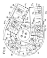
- Fig. 5 is an enlarged view of a relevant portion shown in Fig.4 in a state in which batteries and a control unit have been removed;
- Fig. 6 is an enlarged sectional view taken along a line 6-6 in Fig. 4;
- Fig.7 is an enlarged sectional view taken along a line 7-7 in Fig.6;
- Fig.8 is an enlarged view taken in a direction of an arrow 8 in Fig.4;
- Fig.9 is a sectional view taken along a line 9-9 in Fig.4;
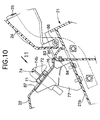
- Fig.10 is an enlarged sectional view taken along a line 10-10 in Fig.3;
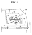
- Fig.11 is a view taken in a direction of an
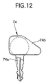
arrow 11 in Fig. 10; - Fig.12 is a side view of a key member; and
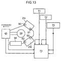
- Fig.13 is a diagram showing a state in which an electric motor, the control unit and the batteries have been electrically connected to one another.
-
- The present invention will now be described by way of an embodiment with reference to Figs.1 to 13. Referring first to Fig.1 to 3, an electric lawn mower M includes a
cutter housing 21 also serving as a vehicle frame. A pair of left and right front wheels WF are mounted at a front portion of thecutter housing 21. A pair of left and right rear wheels WR are mounted at a rear portion of thecutter housing 21. Moreover, the front wheels WF and the rear wheels WR are swingable about horizontal axes, so that a clearance between a ground surface and thecutter housing 21 can be regulated by locking the swung positions of the front wheels WF and the rear wheels WR by a locking means (not shown). - An upper portion of the
cutter housing 21 is covered with a bowl-like housing cover 22. Agrass bag 23, for accommodating lawn clippings, is detachably mounted at a rear end of thecutter housing 21. Adischarge port cover 24 is vertically swingably connected to an upper portion of a rear end of thecutter housing 21. In a state in which thegrass bag 23 has been mounted at the rear end of thecutter housing 21, thedischarge port cover 24 is turnable upwards in a manner that it is retained on thegrass bag 23. - Handlebar stays 25 are secured to left and right opposite sides of the rear end of the
cutter housing 21. Ahandlebar 26 for pushing the electric lawn mower M is connected to the handlebar stays 25. - A
cutter 27 is rotatably accommodated within thecutter housing 21. Anelectric motor 28 for providing a rotational power to thecutter 27 and a pair of batteries 291 and 292 for supplying an electric power to theelectric motor 28 are mounted on thecutter housing 21. - Referring also to Figs.4, 5 and 6, the
cutter housing 21 is provided at its substantially central portion with asupport plate portion 21a which is partially recessed downwards but formed substantially flat. Theelectric motor 28 is fixedly supported on thesupport plate portion 21a through amotor supporting bracket 30. - A circular mounting bore 31 is provided in the
support plate portion 21a. Thecutter housing 21 is provided with bulgedsupport portions support plate portion 21a at right and left locations in front of the mountingbore 31.Bulged support portions support plate portion 21a at right and left locations in a rear of the mountingbore 31. - The
motor supporting bracket 30 is comprised of a flat plate-like base portion 30a inserted into the mountingbore 31. Mounting plate portions 30b1, 30b2, 30b3 and 30b4 are connected to thebase portion 30a at locations corresponding to the bulgedsupport portions support portions bore 31. - Referring also to Fig.7, the bulged
support portions support plate portion 21a, are integrally provided withcylindrical boss portions 34, respectively, which extend downwards and into whichcollars 33 made of a metal are inserted, respectively.Washers 35 abut against lower end of thecollars 33, respectively.Nuts 37 are threadedly fitted over lower ends ofbolts 36 which are inserted through the mounting plate portions 30b1, 30b2, 30b3 and 30b4, thecollars 33 and thewashers 35 in a manner that locking heads at top ends are engaged with the mounting plate portions 30b1, 30b2, 30b3 and 30b4, respectively. Themotor supporting bracket 30 is fixed to the supportingplate portion 21a by tightening the nuts 37. - A circular insertion bore 38 is provided in a central portion of the
base 30a of themotor supporting bracket 30. A lower end of theelectric motor 28, formed cylindrically and having a pair of connectingterminals 39 at its upper end, is inserted from above into the insertion bore 38. Moreover, theelectric motor 28 is provided at its lower portion with aflange 40 which is placed on thebase 30a at a peripheral edge of the insertion bore 38. Theelectric motor 28 is fixed onto themotor supporting bracket 30 by bringingbolts 41 into threaded engagement withnuts 42 welded to thebase 30a.Bolts 41 are passed through theflange 40 and thebase 30a at a plurality of, for example, three points spaced apart from one another circumferentially of theflange 40. - An
output shaft 43 coaxially protrudes from the lower end of theelectric motor 28. Thecutter 27 having, for example, a single blade, is mounted to theoutput shaft 43. - On the right in a direction of forward movement of the electric lawn mower M, as clearly shown in Fig.4, a
discharge port 44 is defined in the rear end of thecutter housing 21, so that the grass pieces cut by thecutter 27 are discharged through thedischarge port 44. - A
scroll portion 21b, which is bulged from an outer edge of thesupport plate portion 21a on the right of theelectric motor 28 and slanted up backwards, is provided on thecutter housing 21 in a manner to guide the cut grass pieces to thedischarge port 44. Thescroll portion 21b is formed into such a shape that thescroll portion 21b widens as it approaches thedischarge port 44. On the other hand, a bulgedslant portion 21c, which is bulged from the outer edge of thesupport plate portion 21a on the left of theelectric motor 28 and sloped up rearwards, is provided on thecutter housing 21 in such a shape that it widens as it approaches thedischarge port 44. Thesupport plate portion 21a, which is sandwiched between thescroll portion 21b and the bulgedslant portion 21c, is formed such that its width becomes smaller as it approaches the discharge port. - A
bracket 46 for a unit is fastened to those mounting plate portions 30b1 and 30b2 of themotor supporting bracket 30 which are disposed in front of theelectric motor 28. Acontrol unit 45, for controlling the operation of theelectric motor 28, is fastened onto theunit bracket 46. More specifically,bolts 47 are inserted through the mounting plate portions 30b1 and 30b2 and theunit bracket 46 at locations offset from the bulgedsupport portions unit bracket 46 is fastened to the mounting plate portions 30b1 and 30b2 by threadedly fitting thebolts 47 into the nuts 48 which are welded to the lower surfaces of the mounting plate portions 30b1. and 30b2. Thecontrol unit 45 is fastened to opposite sides of theunit bracket 46 by a pair ofbolts 49 andnuts 50 which are welded to lower surfaces of opposite sides of theunit bracket 46 for threaded engagement of thebolts 49. - Referring also to Figs.8 and 9, the pair of
batteries 291 and 292 are mounted on thesupport plate portion 21a in an arrangement such that theelectric motor 28 is sandwiched between front ends of the batteries 291 and 292. One battery 291 of the batteries 291 and 292 extends along the inner side of thescroll portion 21b, while the other battery 292 extends along the inner side of the bulgedslant portion 21c, i.e., in an arrangement such that the distance between the rear ends of the batteries 291 and 292 is smaller than the distance between the front ends of the batteries 291 and 292. - The batteries 291 and 292 are fixed onto battery trays 511 and 512. First legs 521 and 522 and second legs 531 and 532 are welded to bottoms of the battery trays 511 and 512. The first legs 521 and 522 are fastened to the mounting plate portions 30b3 and 30b4 provided on the
motor supporting bracket 30 in the rear of theelectric motor 28. The second legs 531 and 532 are fastened directly onto thesupport plate portion 21a in the rear of the first legs 521 and 522. - The first legs 521 and 522 are placed on the mounting plate portions 30b3 and 30b4. Each leg 521 and 522 has a
circular bore 54 which is faced by the locking head of thebolt 36 for fastening the mounting plate portions 30b3 and 30b4 to the bulgedsupport portions bolts 55 are inserted through the first legs 521 and 522 and the mounting plate portions 30b3 and 30b4 at locations offset from the bulgedsupport portions bolts 55 into the nuts 56 which are welded to the lower surfaces of the mounting plate portions 30b3 and 30b4. The batteries trays 511 and 512 are provided at their bottoms with circular operating bores 57 enabling the operation of thebolts -
Bolts 58, passed through thesupport plate portion 21a from below thesupport plate portion 21a, are inserted through the second legs 531 and 532 placed on thesupport plate portion 21a as shown in Fig. 6. The second legs 531 and 532 are fastened onto thesupport plate portion 21a by bringingnuts 59, with thebolts 58 threadedly inserted thereinto, into engagement with the second legs 531 and 532. Moreover, the battery trays 511 and 512 are provided at their bottoms with circular operating bores 60 enabling the operation of the nuts 59. - A retaining
plate 63 is placed onto the batteries 291 and 292 which are mounted on the battery trays 511 and 512. The retainingplate 63 is formed from a metal sheet and includes a firstfitting portion 63a which is formed into a substantially U shape such that it opens downwards and into which the upper portion of one of the batteries 291 is fitted, a secondfitting portion 63b which is formed into a substantially U shape such that it opens downwards and into which the upper portion of the other battery 292 is fitted, a connectingplate portion 63c which interconnects thefitting portions first collar portion 63d protruding outwards from the firstfitting portion 63a, and asecond collar portion 63e protruding outwards from the secondfitting portion 63b. - An upward-extending
locking plate portion 30c is integrally connected to thebase 30a of themotor supporting bracket 30 at a location substantially corresponding to the connectingplate portion 63c of the retainingplate 63. Anut 65 is threadedly fitted over an upper end of abolt 64, which is passed through the connectingplate portion 63c, with its lower end engaged with the lockingplate portion 30c. Lockingplates 66 rise from sides of the battery trays 511 and 512 to above thescroll portion 21b and the bulgedslant portion 21c and are secured to the battery trays 511 and 512 at locations substantially corresponding to the first andsecond collar portions plate 63.Nuts 68 are threadedly fitted over upper ends ofbolts 67, which are passed through thecollar portions plates 66. Thus, the batteries 291 and 292 are fixed onto the battery trays 511 and 512 by tightening the nuts 65 and 68. - Referring also to Figs.10 and 11, a relatively wide space is produced outside the rear end of each of the batteries 291 and 292 above the
cutter housing 21 by the fact that the batteries 291 and 292 are disposed on thecutter housing 21, so that they are gradually spaced apart from each other in a forward direction. To effectively utilize the space, aswitch 71 and aconnector 72, as electric equipment, are fixedly disposed on thescroll portion 21b outside the rear end of the one battery 291. Anindicator 73, as shown in Figs. 3 and 4 as electric equipment, is fixedly disposed on the bulgedslant portion 21c outside the rear end of the other battery 292. - The
switch 71 is capable of being switched over between a first state, in which electric power can be supplied from the batteries 291 and 292 to theelectric motor 28, and a second state, in which electric power cannot be supplied from the batteries 291 and 292 to theelectric motor 28. When theswitch 71 is in the first state, electric power is supplied to theelectric motor 28 to drive thecutter 27 by operating an operating switch 75 (see Fig.1) mounted on ahandlebar 26. Moreover, a key bore 71a is provided in one end of theswitch 71, so that akey member 74 can be removably inserted into the key bore 71a, only when theswitch 71 is in the second state. Theswitch 71 is switched over by turning thekey member 74 while inserted into the key bore 71a, for example, through 90 degree. On the other hand, theconnector 72 is of a female type, to which a male-type connector can be connected. The male-type connector is mounted at a tip end of a connecting cord for supplying a charging electric power from an external power source to the batteries 291 and 292. - Referring to Fig.12, the
key member 74 includes akey body 74a whose one end can be inserted into the key bore 71a, and an operatingportion 74b integrally or detachably provided at the other end of thekey body 74a. The operatingportion 74b is formed into such a shape that it protrudes outwards from thekey body 74a. - A pair of
brackets 77, as shown in Fig. 4, are fastened to the upper surface of thescroll portion 21b. Theswitch 71 is fixed to asupport plate 76 fixed onto thebrackets 77, so that one end thereof protrudes from thesupport plate 76. As clearly shown in Fig.11, an "ON" position and an "OFF" position are indicated on thesupport plate 76 at two points spaced apart at approximately 90 degree from each other around theswitch 71. When the operatingportion 74b of thekey member 74 is in the "ON" position, theswitch 71 assumes the first state in which electric power can be supplied from the batteries 291 and 292 to theelectric motor 28. When the operatingportion 74b is in the "OFF" state, theswitch 71 assumes the second state in which electric power cannot be supplied from the batteries 291 and 292 to theelectric motor 28. - The
connector 72 is fixed to thesupport plate 76 at a portion corresponding to the "ON" position in proximity to theswitch 71. When thekey member 74 is turned so that the operatingportion 74b thereof assumes the "ON" position in order to bring theswitch 71 into the first state, theconnector 72 is covered with the operatingportion 74b, so that the external power source cannot be connected to theconnector 72. - An
indicator 73, as shown in Fig. 4, includes afirst base plate 78, first, second and third indicating lamps 791, 792 and 793 such as luminescent diodes mounted in a line on thefirst base plate 78, and asecond base plate 80 disposed below thefirst base plate 78. Theindicator 73 is fixed onto abracket 81 which is fastened onto the bulgedslant portion 21c. Drive circuits (not shown) for the indicating lamps 791, 792 and 793 are carried on thesecond base plate 80, so that the indicating lamps 791, 792 and 793 are turned on depending upon the remaining capacity of the batteries 291 and 292. Moreover, the first and second indicating lamps 791 and 792 are green, and the third indicating lamp 793 is red. When the batteries 291 and 292 are in their fully charged states, the first and second green lamps 791 and 792 are turned on. When the batteries 291 and 292 reaches their semi-charged states, the first indicating lamp 791 is turned off, while the second indicating lamp 792 remains turned on. Further, when charging of the batteries 291 and 292 is required, the first and second green lamps 791 and 792 are turned off, while the third red indicating lamp 793 is turned on. - The remaining capacity of the batteries 291 and 292 is clearly indicated by changing of the on-off modes of the indicating lamps 791, 792 and 793 in the above manner. When charging of the batteries 291 and 292 is required, a user is thus informed. Thus, the life of the batteries 291 and 292 can be prolonged.
- The
electric motor 28, the batteries 291 and 292, thecontrol unit 45, theswitch 71, theconnector 72 and theindicator 73 are disposed on thecutter housing 21 in an arrangement as shown in Fig.13. One battery 291 of the batteries 291 and 292 is disposed on the right of theelectric motor 28 with itsminus terminal 90 located at the front and itsplus terminal 91 located at the rear. The other battery 292 is disposed on the left of theelectric motor 28 with itsminus terminal 92 located at the rear and itsplus terminal 93 located at the front. Therefore, electric connection between thecontrol unit 45, which is disposed in front of theelectric motor 28 and connected to theelectric motor 28 through a pair of cables, and the batteries 291 and 292, which are connected in series, is achieved by sequentially connecting thecontrol unit 45 with theminus terminal 90 of the one battery 291, theplus terminal 91 of the one battery 291 with theminus terminal 92 of the other battery 292, and theplus terminal 93 of the other battery 292 with thecontrol unit 45. Thus, the connecting wiring between thecontrol unit 45 and the batteries 291 and 292 can be simplified. Afuse 94 is mounted between theplus terminal 93 of the other battery 292 and thecontrol unit 45. - The
control unit 45 and theindicator 73 are connected to each other, for example, through a 6-core flat cable, and theswitch 71, theconnector 72 and theoperating switch 75 are also connected to theindicator 73. - The
housing cover 22 is mounted to thecutter housing 21, so that it covers theelectric motor 28, the batteries 291 and 292 and thecontrol unit 45 which are mounted on thecutter housing 21. Theswitch 71, theconnector 72 and the first, second and third indicating lamps 791, 792 and 793 are exposed to the outside. Thehousing cover 22 is fastened at its front portion to thecutter housing 21 by a pair of threaded members 82 (see Fig.1). Engagemembers 83 are secured to the rear portion of thecutter housing 21 byclips 84 at two points spaced apart from each other in a widthwise direction of thecutter housing 21. The rear portion of thehousing cover 22 is resiliently engaged with the engagemembers 83. Moreover,notches 85 are provided at the rear end of thehousing cover 22, as shown in Fig.10, and the engagemembers 83 are fitted into thenotches 85. Thus, the looseness of thehousing cover 22 in the widthwise direction of thecutter housing 21 is inhibited by the fitting of the engagemembers 83 into thenotches 85. - An
opening 87, for outside exposure of theswitch 71 and theconnector 72, is provided in the rear portion of thehousing cover 22, so that it is closed by thesupport plate 76. Anopening 88, for outside exposure of the first, second and third indicating lamps 791, 792 and 793, is also provided in the rear portion of thehousing cover 22, so that it is closed by thefirst base plate 78. - The
discharge port cover 24 is turnably supported at its front end on the rear end of thecutter housing 21 through asupport shaft 86. Thecover 24 is swingable between an opened position (a position shown in Fig. 1) in which it has been swung upwards and retained above thegrass bag 23, and a closed position in which, when the grass bag has been removed, the discharge port cover 24 covers thedischarge port 44 in thecutter housing 21. The lower end of thedischarge port cover 24 serves as a discharge bore. - The operation of this embodiment will be described below. Since the pair of batteries 291 and 292 are mounted on the
cutter housing 21 in such a manner that the front ends thereof are disposed on opposite sides of theelectric motor 28, the lateral weight balance of thecutter housing 21 is substantially uniform, thereby enhancing the travelability of the electric lawn mower M. Moreover, the longitudinal length of the space, which should be ensured above thecutter housing 21 in rear of theelectric motor 28 for mounting the batteries 291 and 292, can be relatively shortened, whereby the longitudinal length of thecutter housing 21 can be relatively shortened. In addition, since theelectric motor 28 is connected directly to thecutter 27, a space for disposing the power transmitting means between theelectric motor 28 and thecutter 27 is not required above thecutter housing 21. Hence, thecutter housing 21 can be more compact since the longitudinal lengths can be shortened. - One battery 291 of the batteries 291 and 292 is disposed along the inner side of the
scroll portion 21b which is widened as it approaches thedischarge port 44. Thus, the area of thedischarge port 44 cannot be narrowed due to the mounting of the pair of batteries 291 and 292. In addition, since the batteries 291 and 292 are mounted on thesupport plate portion 21a lying at a relatively low level, they can be mounted at a relatively low location on thecutter housing 21 which lowers the center of gravity of the traveling section including thecutter housing 21 and which suppresses the height of the traveling section to a relatively low level. - Additionally, since the batteries 291 and 292 are disposed with the distance between their front ends being larger than the distance between their rear ends, a relatively wide space can be ensured above the
cutter housing 21 outside the rear ends of the batteries 291 and 292. As a result, theswitch 71, theconnector 72 and theindicator 73 can be fixedly mounted outside the rear ends of the batteries 291 and 292, and disposed effectively utilizing the space without increasing the width of thecutter housing 21. - Moreover, one battery 291 of the batteries 291 and 292 is disposed on either the left or right side of the
electric motor 28 with itsminus terminal 90 located at the front and itsplus terminal 91 located at the rear. The other battery 292 is disposed on the other of the left or right side of theelectric motor 28 with itsminus terminal 92 located at the rear and itsplus terminal 93 located at the front. Therefore, the electric connection between the batteries 291 and 292, which are connected in series, and thecontrol unit 45 is achieved by sequentially connecting the batteries 291 and 292 and thecontrol unit 45 in one direction around theelectric motor 28. Thus, the connecting wiring between thecontrol unit 45 and the batteries 291 and 292 can be simplified. - The
key member 74, for switching theswitch 71, is comprised of thekey body 74a whose one end can be inserted into and removed from the key bore 71a in theswitch 71, and the operatingportion 74b integrally or removably provided at the other end of thekey body 74a to protrude sideways from thekey body 74a. When thekey member 74 has been operated to the "ON" position, theconnector 72 is covered by the operatingportion 74b of thekey member 74, so that it cannot be connected to an external power source. Therefore, theswitch 71 can be switched between the state in which electric power can be supplied to theelectric motor 28 and the batteries 291 and 292 cannot be charged, and the state in which electric power cannot be supplied to theelectric motor 28 and the batteries 291 and 292 can be charged by the simple operation of only turning thekey member 74 which is not withdrawn from theswitch 71 with a simple structure without other parts than theswitch 71, thekey member 74, and theconnector 72. - Although the present invention has been described as being applied to the electric lawn mower M in the embodiment, the present invention is applicable to an electric lawn mower adapted to cut grass other than a lawn. In addition, although the bulged
slant portion 21c which is bulged to become higher at its rear portion, as is thescroll portion 21b, has been provided on the left of thecutter housing 21 in the embodiment, a portion corresponding to the bulgedslant portion 21c may be formed substantially flat. Further, although the electric lawn mower has been described in the embodiment as designed to be pushed, the present invention is applicable to an electric lawn mower designed to automatically move due to power from theelectric motor 28. In this case, a transmitting device such as a transmission can be effectively accommodated in the bulgedslant portion 21c which is bulged to become higher at its rear portion, as is thescroll portion 21b.
Claims (3)
- An electric lawn mower comprising:a cutter housing (21) including front and rear wheels (WF, WR) ;a cutter (27) rotatably accommodated in the cutting housing;an electric motor (28) mounted on the cutter housing for providing rotational power to the cutter; anda pair of batteries (291, 292) mounted on the cutter housing for supplying electric power to said electric motor;wherein said cutter housing has a discharge port (44) defined in a rear end thereof for discharging grass cuttings cut by said cutter;a support plate portion (21a) mounting the electric motor which is disposed at a substantially central region of said cutter housing and which is connected directly to said cutter; anda scroll portion (21b) which is bulged from an outer edge of the support plate portion on either the left or right side of said electric motor to guide the grass cuttings to said discharge port and which is formed into a shape that slopes up rearwards and widens approaching said discharge port; andwherein said batteries are mounted on said support plate portion in an arrangement such that one of said batteries extends along an inner side of said scroll portion and said electric motor is sandwiched between the front ends of said batteries.
- An electric lawn mower comprising:a cutter housing (21) including front and rear wheels (WF, WR) ;a cutter (27) rotatably accommodated in said cutter housing;an electric motor (28) mounted on said cutter housing for providing rotational power to said cutter; anda pair of batteries (291, 292) mounted on said cutter housing for supplying electric power to said electric motor;wherein said electric motor is mounted at a substantially central region of said cutter housing and is connected directly to said cutter;said batteries are mounted on said cutter housing in an arrangement such that said electric motor is sandwiched between the front ends of said batteries and the distance between the rear ends of said batteries is smaller than the distance between the front ends thereof; andsaid electric lawn mower further includes electric equipment fixedly disposed on said cutter housing outside of the rear ends of the batteries, respectively.
- An electric lawn mower according to claim 1 or 2, further including a control unit (45) mounted on said cutter housing (21) in front of said electric motor (28) for controlling operation of said electric motor, and wherein one of said batteries (291, 292), which are connected in series, is disposed on either the left or right side of said electric motor with a minus terminal located at the front and a plus terminal located at the rear, while the other battery is disposed on the other side of said electric motor with a plus terminal located at the front and a minus terminal located at the rear.
Applications Claiming Priority (6)
| Application Number | Priority Date | Filing Date | Title |
|---|---|---|---|
| JP508997 | 1997-01-14 | ||
| JP508997 | 1997-01-14 | ||
| JP5089/97 | 1997-01-14 | ||
| JP29084697A JP3433069B2 (en) | 1997-01-14 | 1997-10-23 | Electric lawn mower |
| JP29084697 | 1997-10-23 | ||
| JP290846/97 | 1997-10-23 |
Publications (2)
| Publication Number | Publication Date |
|---|---|
| EP0852904A1 EP0852904A1 (en) | 1998-07-15 |
| EP0852904B1 true EP0852904B1 (en) | 2001-05-09 |
Family
ID=26338977
Family Applications (1)
| Application Number | Title | Priority Date | Filing Date |
|---|---|---|---|
| EP98300216A Expired - Lifetime EP0852904B1 (en) | 1997-01-14 | 1998-01-13 | Electric lawn mower |
Country Status (4)
| Country | Link |
|---|---|
| US (1) | US5953890A (en) |
| EP (1) | EP0852904B1 (en) |
| JP (1) | JP3433069B2 (en) |
| DE (1) | DE69800758T2 (en) |
Families Citing this family (16)
| Publication number | Priority date | Publication date | Assignee | Title |
|---|---|---|---|---|
| TWM278226U (en) | 2001-08-22 | 2005-10-21 | Honda Motor Co Ltd | Electric lawn mower |
| TWI248783B (en) * | 2001-08-22 | 2006-02-11 | Honda Motor Co Ltd | Electric lawn mower |
| JP3776773B2 (en) * | 2001-08-22 | 2006-05-17 | 本田技研工業株式会社 | Electric lawn mower |
| US20070199291A1 (en) * | 2006-02-27 | 2007-08-30 | Roosevelt Tharp | Non chargeable electric lawn mower |
| WO2008048618A2 (en) | 2006-10-17 | 2008-04-24 | Desa Ip. Llc | Hybrid electric device |
| US7728534B2 (en) | 2006-10-17 | 2010-06-01 | Mtd Products Inc | Hybrid electric lawnmower |
| US7479754B2 (en) | 2006-10-17 | 2009-01-20 | Desa Ip Llc | Hybrid electric lawnmower |
| US8732896B2 (en) | 2006-10-17 | 2014-05-27 | Mtd Products Inc | Hybrid electric cleaning device |
| US8076873B1 (en) | 2007-06-01 | 2011-12-13 | Mtd Products Inc | Hybrid outdoor power equipment |
| CN101790921B (en) * | 2010-03-11 | 2012-05-02 | 常州合力电器有限公司 | Anti-dumping hand-push electrical mower |
| US8272197B2 (en) * | 2010-06-15 | 2012-09-25 | Man-Young Jung | Handheld lawn mower |
| JP5689753B2 (en) * | 2011-06-14 | 2015-03-25 | 株式会社マキタ | Electric lawn mower |
| JP6088914B2 (en) * | 2013-06-11 | 2017-03-01 | 株式会社クボタ | Walking mower |
| CN105794388A (en) * | 2014-12-30 | 2016-07-27 | 南京德朔实业有限公司 | Power tool |
| CN106258180B (en) * | 2015-05-20 | 2019-03-08 | 南京德朔实业有限公司 | walk mower |
| US10765061B2 (en) | 2018-07-31 | 2020-09-08 | Honda Motor Co., Ltd. | Cover attachment for lawnmower cutter housing |
Family Cites Families (10)
| Publication number | Priority date | Publication date | Assignee | Title |
|---|---|---|---|---|
| US2597735A (en) * | 1946-09-13 | 1952-05-20 | Sunbeam Corp | Lawn mower |
| BE742969A (en) * | 1969-04-15 | 1970-05-14 | ||
| US4064680A (en) * | 1975-08-08 | 1977-12-27 | The Black And Decker Manufacturing Company | Cordless twin blade lawnmower construction |
| JP2898408B2 (en) * | 1990-04-10 | 1999-06-02 | アール. ペイタス,アントニ | Solar powered lawn mower |
| DE4137162A1 (en) * | 1991-11-12 | 1993-05-13 | Wolf Dietrich Zinck | Battery-operated electric lawnmower using permanent D.C. motor - with battery simply electrically disconnected and removed for replacement without requiring any special tools |
| US5606851A (en) * | 1993-09-22 | 1997-03-04 | Briggs & Stratton Corporation | Battery-powered lawn cutting system |
| US5442901A (en) * | 1994-07-22 | 1995-08-22 | Ryobi North America | Self-propelled mower |
| US5502957A (en) * | 1995-03-29 | 1996-04-02 | Robertson; Charles W. | Electric lawn mower with intelligent control |
| DE29513479U1 (en) * | 1995-08-22 | 1995-11-02 | Viking-Umwelttechnik Ges.M.B.H., Kufstein | Lawn mower drive |
| JPH09201126A (en) * | 1995-11-24 | 1997-08-05 | Honda Motor Co Ltd | Electric lawn mower |
-
1997
- 1997-10-23 JP JP29084697A patent/JP3433069B2/en not_active Expired - Fee Related
-
1998
- 1998-01-09 US US09/005,047 patent/US5953890A/en not_active Expired - Lifetime
- 1998-01-13 DE DE69800758T patent/DE69800758T2/en not_active Expired - Lifetime
- 1998-01-13 EP EP98300216A patent/EP0852904B1/en not_active Expired - Lifetime
Also Published As
| Publication number | Publication date |
|---|---|
| DE69800758D1 (en) | 2001-06-13 |
| JPH10257814A (en) | 1998-09-29 |
| EP0852904A1 (en) | 1998-07-15 |
| US5953890A (en) | 1999-09-21 |
| JP3433069B2 (en) | 2003-08-04 |
| DE69800758T2 (en) | 2002-02-28 |
Similar Documents
| Publication | Publication Date | Title |
|---|---|---|
| EP0853354B1 (en) | Electric working machine and interlock system therefor | |
| US5953890A (en) | Electric lawn mower | |
| US11839178B2 (en) | Electric riding lawn mower | |
| JP2880116B2 (en) | Power head assembly for electric mower | |
| EP1285567B1 (en) | Electric working machine | |
| US5894715A (en) | Mounting apparatus for connecting a power head to a device | |
| US20030037525A1 (en) | Electric lawn mower | |
| CA2391266C (en) | Electric lawn mower | |
| EP4324321A1 (en) | Ride-on mowing device | |
| CN218634775U (en) | Mowing tractor | |
| US20230389476A1 (en) | Electric riding lawn mower | |
| CN218680092U (en) | Mowing tractor | |
| US6944979B2 (en) | Snow removing machine | |
| CN218892647U (en) | Saddle-riding type vehicle | |
| CN116114460A (en) | Riding type mowing equipment | |
| CN116118915A (en) | Saddle-riding type vehicle | |
| CN116114457A (en) | Mowing tractor | |
| WO2023082770A1 (en) | Ride-on lawn mowing apparatus | |
| CN116118497A (en) | Mowing tractor | |
| JPH0471410A (en) | Small-sized lawn mower |
Legal Events
| Date | Code | Title | Description |
|---|---|---|---|
| PUAI | Public reference made under article 153(3) epc to a published international application that has entered the european phase |
Free format text: ORIGINAL CODE: 0009012 |
|
| AK | Designated contracting states |
Kind code of ref document: A1 Designated state(s): DE FR GB IT |
|
| AX | Request for extension of the european patent |
Free format text: AL;LT;LV;MK;RO;SI |
|
| 17P | Request for examination filed |
Effective date: 19980604 |
|
| AKX | Designation fees paid |
Free format text: DE FR GB IT |
|
| RBV | Designated contracting states (corrected) |
Designated state(s): DE FR GB IT |
|
| GRAG | Despatch of communication of intention to grant |
Free format text: ORIGINAL CODE: EPIDOS AGRA |
|
| 17Q | First examination report despatched |
Effective date: 20000808 |
|
| GRAG | Despatch of communication of intention to grant |
Free format text: ORIGINAL CODE: EPIDOS AGRA |
|
| GRAH | Despatch of communication of intention to grant a patent |
Free format text: ORIGINAL CODE: EPIDOS IGRA |
|
| GRAH | Despatch of communication of intention to grant a patent |
Free format text: ORIGINAL CODE: EPIDOS IGRA |
|
| GRAA | (expected) grant |
Free format text: ORIGINAL CODE: 0009210 |
|
| ITF | It: translation for a ep patent filed | ||
| AK | Designated contracting states |
Kind code of ref document: B1 Designated state(s): DE FR GB IT |
|
| REF | Corresponds to: |
Ref document number: 69800758 Country of ref document: DE Date of ref document: 20010613 |
|
| ET | Fr: translation filed | ||
| REG | Reference to a national code |
Ref country code: GB Ref legal event code: IF02 |
|
| PLBE | No opposition filed within time limit |
Free format text: ORIGINAL CODE: 0009261 |
|
| STAA | Information on the status of an ep patent application or granted ep patent |
Free format text: STATUS: NO OPPOSITION FILED WITHIN TIME LIMIT |
|
| 26N | No opposition filed | ||
| PGFP | Annual fee paid to national office [announced via postgrant information from national office to epo] |
Ref country code: IT Payment date: 20120118 Year of fee payment: 15 |
|
| PGFP | Annual fee paid to national office [announced via postgrant information from national office to epo] |
Ref country code: DE Payment date: 20130109 Year of fee payment: 16 Ref country code: FR Payment date: 20130204 Year of fee payment: 16 Ref country code: GB Payment date: 20130109 Year of fee payment: 16 |
|
| REG | Reference to a national code |
Ref country code: DE Ref legal event code: R119 Ref document number: 69800758 Country of ref document: DE |
|
| GBPC | Gb: european patent ceased through non-payment of renewal fee |
Effective date: 20140113 |
|
| REG | Reference to a national code |
Ref country code: DE Ref legal event code: R119 Ref document number: 69800758 Country of ref document: DE Effective date: 20140801 |
|
| PG25 | Lapsed in a contracting state [announced via postgrant information from national office to epo] |
Ref country code: DE Free format text: LAPSE BECAUSE OF NON-PAYMENT OF DUE FEES Effective date: 20140801 |
|
| REG | Reference to a national code |
Ref country code: FR Ref legal event code: ST Effective date: 20140930 |
|
| PG25 | Lapsed in a contracting state [announced via postgrant information from national office to epo] |
Ref country code: FR Free format text: LAPSE BECAUSE OF NON-PAYMENT OF DUE FEES Effective date: 20140131 Ref country code: GB Free format text: LAPSE BECAUSE OF NON-PAYMENT OF DUE FEES Effective date: 20140113 |
|
| PG25 | Lapsed in a contracting state [announced via postgrant information from national office to epo] |
Ref country code: IT Free format text: LAPSE BECAUSE OF NON-PAYMENT OF DUE FEES Effective date: 20140113 |