EP0852827B1 - Modular terminal block assembly - Google Patents
Modular terminal block assembly Download PDFInfo
- Publication number
- EP0852827B1 EP0852827B1 EP96935863A EP96935863A EP0852827B1 EP 0852827 B1 EP0852827 B1 EP 0852827B1 EP 96935863 A EP96935863 A EP 96935863A EP 96935863 A EP96935863 A EP 96935863A EP 0852827 B1 EP0852827 B1 EP 0852827B1
- Authority
- EP
- European Patent Office
- Prior art keywords
- terminal block
- module
- connection
- block assembly
- distribution
- Prior art date
- Legal status (The legal status is an assumption and is not a legal conclusion. Google has not performed a legal analysis and makes no representation as to the accuracy of the status listed.)
- Expired - Lifetime
Links
Images





Classifications
-
- H—ELECTRICITY
- H01—ELECTRIC ELEMENTS
- H01R—ELECTRICALLY-CONDUCTIVE CONNECTIONS; STRUCTURAL ASSOCIATIONS OF A PLURALITY OF MUTUALLY-INSULATED ELECTRICAL CONNECTING ELEMENTS; COUPLING DEVICES; CURRENT COLLECTORS
- H01R9/00—Structural associations of a plurality of mutually-insulated electrical connecting elements, e.g. terminal strips or terminal blocks; Terminals or binding posts mounted upon a base or in a case; Bases therefor
- H01R9/22—Bases, e.g. strip, block, panel
- H01R9/24—Terminal blocks
- H01R9/2408—Modular blocks
-
- H—ELECTRICITY
- H01—ELECTRIC ELEMENTS
- H01R—ELECTRICALLY-CONDUCTIVE CONNECTIONS; STRUCTURAL ASSOCIATIONS OF A PLURALITY OF MUTUALLY-INSULATED ELECTRICAL CONNECTING ELEMENTS; COUPLING DEVICES; CURRENT COLLECTORS
- H01R9/00—Structural associations of a plurality of mutually-insulated electrical connecting elements, e.g. terminal strips or terminal blocks; Terminals or binding posts mounted upon a base or in a case; Bases therefor
- H01R9/22—Bases, e.g. strip, block, panel
- H01R9/24—Terminal blocks
- H01R9/2425—Structural association with built-in components
- H01R9/2441—Structural association with built-in components with built-in overvoltage protection
-
- H—ELECTRICITY
- H04—ELECTRIC COMMUNICATION TECHNIQUE
- H04Q—SELECTING
- H04Q1/00—Details of selecting apparatus or arrangements
- H04Q1/02—Constructional details
- H04Q1/14—Distribution frames
- H04Q1/142—Terminal blocks for distribution frames
-
- H—ELECTRICITY
- H04—ELECTRIC COMMUNICATION TECHNIQUE
- H04Q—SELECTING
- H04Q1/00—Details of selecting apparatus or arrangements
- H04Q1/02—Constructional details
- H04Q1/14—Distribution frames
- H04Q1/146—Distribution frames with line protection means
-
- H—ELECTRICITY
- H04—ELECTRIC COMMUNICATION TECHNIQUE
- H04Q—SELECTING
- H04Q2201/00—Constructional details of selecting arrangements
- H04Q2201/14—Screening, grounding or crosstalk reduction details
-
- H—ELECTRICITY
- H04—ELECTRIC COMMUNICATION TECHNIQUE
- H04Q—SELECTING
- H04Q2201/00—Constructional details of selecting arrangements
- H04Q2201/18—Rails
Definitions
- the present invention relates to a communication connector terminal block assembly system and more particularly to modular terminal block assemblies for termination of distribution lines and interconnection with service lines.
- a variety of communication line connector terminal block assemblies are available to terminate and interconnect communication company distribution lines with customer service lines. While some of these terminal blocks provide adequate termination and interconnection, all of the terminal blocks encounter some form of problem which degrade the efficiency, integrity or other characteristics of the system.
- U-shaped frame for mounting multiple terminal blocks.
- the U-shaped frame with the multiple terminal blocks attached thereto can then be attached to a cabinet or large multi-unit frame.
- advantages to the U-shaped frame assembly not to mention acceptance and application in many interconnection systems.
- a second type of equipment mounting frame system is a rod system.
- the rod system employs two parallel rods which are spaced apart a predetermined distance so that terminal blocks may be attached thereto.
- One advantage of the rod system over the U-shaped frame system is that the terminal blocks may be closely spaced or positioned abutting one another allowing denser packing and greater space efficiency.
- the terminal blocks are typically attached to the rod to allow a terminal block to be retained on one rod and disengageable from the other rod to allow pivotal access to both sides of the terminal block.
- terminal blocks may be available for mounting to either the U-shaped frame or the rod assembly, many terminal blocks cannot be used with both equipment mounting systems. As such, there is a need for a terminal block which can be used with either the U-shaped frame mounting system or the rod structure mounting system.
- terminal blocks are typically designed for either internal use or external use.
- Most terminal blocks are designed for internal use.
- An enclosure or other environmental protection structure is provided around the terminal block. This is common when the terminal blocks are mounted within a building or other facility which provides protection from harsh environmental effects.
- the components of the terminal block still may be exposed to detrimental environmental effects. For example, dust, moisture, and airborne particulates are attracted to, accumulate on, and create a film on the exposed conductive components. The moisture, particulates and film cause detrimental microscopic corrosion on the conductive components and degrade the operation of the assembly. As such, even in internal uses, it may be desirable to provide environmental protection of the terminal blocks.
- terminal blocks are designed for external use.
- the external terminal block are typically designed as a separate assembly from the internal terminal blocks. It would be desirable to provide a single terminal block assembly system which can be used internally or externally in order to exploit efficiencies which would be inherent in such a universal design. For example, cost efficiencies may be exploited since one type of terminal block assembly system is produced for internal and external uses. There are skill efficiencies which result from the tradesperson having to be familiar with only one type of structure. The skill efficiencies translate into installation reliability since fewer installation errors will be encountered. Further, replacement parts and expansion requirements can be more quickly accommodated since inventories of only one type of terminal block assembly system need to be maintained.
- prior art terminal blocks do not provide constant line protection.
- Some prior art terminal blocks provide line protection but the line protection devices are attached to the customer service connection portion of the terminal block. This is a problem because the protection must be removed in order to access the customer service line. When the protection device is removed, the personnel working on the system and the equipment connected to the system are not protected. It is important to provide constant line protection for both personnel and equipment.
- some available terminal blocks do not provide line isolation for two-way testing. When there is a line failure, it is important to be able to isolate the customer service line from the distribution line to permit tracing of the line problem. Because prior art terminal blocks do not provide line isolation, it is very difficult to trace and identify line fault problems. As such, it would be highly desirable to provide line isolation and testing capabilities in a terminal block assembly system.
- terminal blocks do not provide the ability to selectively attach half-tap assemblies. While some terminal blocks may provide half-tap assemblies, the block must be specifically ordered with this feature. Such a specialized terminal block increases inefficiencies associated with the system and therefore is undesirable. It would be desirable to provide a terminal block assembly system in which half-tap assemblies may be selectively added as needed for specific lines.
- a general object of the claimed invention is to provide a modular terminal block assembly which includes several modules for the termination of distribution lines and service lines.
- Another object satisfied by the claimed invention is to provide a modular terminal block assembly which can be used in an internal or external environment such that in the external environment, the assembly can provide environmental protection.
- Still another object satisfied by the claimed invention is to provide a modular terminal block assembly to which a protection module may be attached and which protection module provides constant line protection.
- Yet a further object satisfied by the claimed invention is to provide a modular terminal block assembly to which a half-tap assembly may be added.
- Still a further object satisfied by the claimed invention is to provide a modular terminal block assembly which provides line isolation and test port capabilities associated with each side of the interconnected line when the line connectors are isolated.
- the modular terminal block assembly includes a base module in which communications company lines may be dressed and retained during the dressing operation.
- a connector module is provided for attachment over the base module and to engage the distribution lines retained in the base module with insulation displacement connectors (IDC) which are retained in the connector module.
- a protection module is provided for engagement with an opposite side of the base module so that protection can be provided on the lines without interfering with the connection termination of customer service line on the connector module.
- the modular terminal block assembly provides structures which allow the assembled modular terminal block to be retained on a standard U-shaped mounting frame or for attachment to a rod frame system.
- the protection module maintains protection on the lines while the terminal block assembly is in contact with the U-shaped frame and rod frame system.
- a half-tap assembly may be attached to the modular terminal block, independent of the service line assembly for the addition of a line to the terminal block.
- An environmental protectant is retained in the modular terminal block to protect the conductive connections retained therein from detrimental environmental effects.
- a modular terminal block assembly 20 is shown mounted to a rod frame structure 22 (see FIG. 1) and to a U-shaped frame 24 (see FIG. 2).
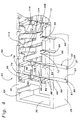
- the terminal block assembly 20 has been exploded to show the various modules and components associated with each module. More particularly, with reference to FIG. 3, there is shown a connector module 26 having a connector module housing 27, a base module 28 having a base module housing 29, and a protection module 30 having a protection module housing 31.
- the base module 28 has a first side 32 and a second side 34.
- the connector module 26 attaches to the first side 32 of the base module 28 and the protection module 30 attaches to the second side 34 of the base module 28.
- the terminal block assembly 20 can be attached to the rod frame system 22 or to the U-shaped frame 24 without using any additional mounting components as required with some prior art devices.
- rod-mounting structures 36 are provided on the protection module 30 for attaching the assembly 20 to a rod frame mounting system 22.
- the present invention also provides frame mounting structures 38 which in the form of apertures 38 formed through each of the modules 26, 28, 30 at opposed ends of the modules.
- the assembly may be used with or without the protection module 30. If the assembly is used without the protection module 30 (see the lower portion of FIG. 2) mounting flanges 40 of the U-shaped frame 24 are inserted through the frame mounting apertures 38 with a biased locking finger 42 engaging an opening 44 in the flange 40.
- the flange 40 is inserted into the frame mounting apertures 38.
- a biased portion 46 of a grounding bar structure 48 retained in the protection module 30 is biased into conductive contact against an inside surface 50 of the U-shaped frame 24.
- distribution lines 52 are retained between the connector module 26 and the base module 28 and service lines 54 are connected to a service connection assembly 56 on the connector module 26.
- a second set of service lines 58 may also be attached to a half-tap assembly 60 on the connector module 26.
- the lines 52, 54, 58 are shown in partial perspective view, these lines 52, 54, 58 may be groomed or retained in grooming rings 62 on either side of the connector module 26.
- the lines 52, 54, 58 may also be groomed rearwardly behind the module 20 in accordance with standard line dressing practices.
- the base module 28 is more fully described.
- the first side 32 of the base module 28 includes a plurality of wire dressing structures 64.
- These wire dressing structures 64 are arranged to be associated and paired with a corresponding service connection assembly 56 of the connector module 26.
- each pair of lines or wire dressing structures 64 will be placed in connection with a corresponding service connection assembly 56.
- This also positions the pairs of wire dressing structures 64 for connection with corresponding half-tap assemblies 60 which may be attached to corresponding half-tap areas 65.
- Locking fingers 66 on the base module 28 engage and retain the connector module 26 in connection with the base module 28.
- the wire dressing structures 64 include a wire receiving channel 68 extending transversely through the first side 32 of the base module 28.
- FIG. 4 shows two distribution lines 52 placed in corresponding wire receiving channels 68 and two channels 68 in which distribution clips 72 are positioned transversely to the channels 68 for engaging a wire placed therein. It should be noted that wires have not been included in the channels over which the distribution clip 72 have been positioned in the interest of clarity.
- the distribution clips 72 have insulation displacement fingers 86 (hereinafter referred to as "IDC fingers 86") which straddle the channel 68 to displace insulation 87 surrounding the lines 52 and conductively engage a conductor 89 within the lines 52.
- IDC fingers 86 are received in the clip receiving well 84.
- Line positioning guide structures 88 are positioned on both sides of the channel 68 between the entry end 80 and the well 84 and the strain relief 82 in the well 84.
- the guide structures 88 quickly and efficiently guide a line 52 into the channel 68 with the strain relief structure 82 positively retaining the line 52 in the channel 68.
- the strain relief structures 82 are formed of a non-conductive material and are intended not to contact the conductor 89 within the line 52.
- the strain relief structures 82 also positively retains dressed lines in place as other lines are being dressed into the base module. The feature permits numerous lines to be dressed and then generally simultaneously connected. In the present invention 10 pairs of lined may be retained in the base module and generally simultaneously connected when the connector module is attached to the base module.
- An alignment post 90 extends upwardly from the first side 32 to provide a positive positioning and alignment guide.
- the alignment post 90 engages an alignment groove 92 formed in the underside of the connector module 26.
- the combination of the trimming structure 78 engaging the well 76 for trimming the ends of the lines 52 and the post 90 engaging the groove 92 as well as end tabs 94 engaging end apertures 96 provides positive alignment of the connector module 26 with the base module 28.
- the trimming structures 76 are formed with varying degrees of extension from the underside of the connector module 26 so as to sequentially trim the lines as the modules 26, 28 are assembled.
- the incremental trimming of the lines reduces the forces that are required such that only a portion of the total number of line 52 are trimmed as the modules 26, 28 are engaged.
- This trimming arrangement helps reduce the trimming forces required thereby making it easier for the tradesperson to assemble the modular assembly system and to prevent assembly errors.
- the asymmetry of abutting portions of the connector module 26 and the base module 28 require that the modules 26,28 be in proper alignment for assembly thereby preventing any chance of assembling the modules 26, 28 in an incorrect position.
- the present invention provides a high degree of environmental protection for the distribution line 52 retained in the base module 28 and connected to the connector module 26.
- Environmental protection is provided by means of a suitable gel, grease or other non-conductive environmentally protecting material of known composition.
- a suitable gel, grease or other non-conductive environmentally protecting material of known composition.
- a non-conductive material referred to as "grease” is used with present invention.
- Grease is used because it is less expensive, easier to use during the manufacturing process and readily available and easy to use in the field for maintenance or repairs.
- the environmental protection material is not illustrated in the figures in the interest of clarity.
- the material is positioned in the well 76, the clip receiving well 84, and the cavity 100 of the connector module 26 and a cavity 101 of the half-tap assembly 60.
- These wells or cavities 76, 84, 100, 101 are the areas in which the conductive components of the lines 52, 54, 58 will be exposed or might be exposed.
- the lines 52 are protected against the detrimental environmental effects such as moisture and particulates and the resulting corrosion.
- FIG. 6 provides an enlarged, top, perspective view of the connector module 26.
- the connector module 26 includes the service connection assembly 56 and the half-tap assembly 60.
- the service connection assemblies 56 include a cavity 100 formed in the connector module 26 and an actuator 102 which slidably engages the cavity 100.
- the half-tap assembly 60 includes a half-tap housing 104 and an actuator 102. It should be noted that the same actuator 102 is used with the service connection assembly 56 and the half-tap assembly 60.
- the half-tap assembly 60 may be selectively attached to the connected module 26 as a second line, coupled to, but independent from, the service line. Similarly, the half-tap assembly 60 may be removed from the connector module 26 if the second line is no longer needed.
- a plurality of connector assemblies 56 and half-tap assemblies 60 are positioned along the connector assembly 26 in an orientation which prevents the half-tap assembly 60 from interfering with the connector assembly 56. In other words, the half-tap assembly 56 is not carried on and does not obstruct access to the connector assembly 56. Positioning the half-tap assemblies 60 on the same side of the connector module as the connector assemblies 56 in a back-to-back orientation also reduces a height dimension 105 of the modular assembly relative to the mounting frame (see FIGS. 1 and 2). Further, the independent attachment of the half-tap assembly 60 to the connector module 26 in the half-tap area 65 prevents having to disturb both lines to carry out an operation on one of the lines.
- prior art devices may provide half-tap assemblies, these prior art half-tap assemblies interfere with or are directly connected to the primary service line. Also, some prior art devices may provide a half-tap assembly integral with the service line assemblies and thus do not allow for selective addition or removal of half-tap assemblies. The prior art devices do not provide the ease of access as does the present invention, nor do such prior art devices provide the selective modularity of the present invention.
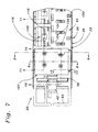
- FIG. 7 provides an enlarged, partial fragmentary, top plan view of the connector terminal block assembly system 20 as shown in FIG. 2.
- the cross sections therethrough provide additional details of the various structures and functions of the assembly system 20 of the present invention.
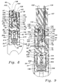
- a modular test probe assembly 107 is shown in FIGS. 7 and 9. The test probe assembly 107 has been removed from FIG. 8 in the interest of showing the assembly 20 without the test probe assembly 107.
- the connector module 26 is shown attached to the base module 28, and the base module 28 is shown attached to the protection module 30.
- An electrical connection is made between the service connection assembly 56 and the distribution clip 72 by a service clip 110.
- the service clip 110 and the distribution clip 72 are retained in the connector module 26 for engagement with the lines retained on the base module 28.
- An isolation leg 112, 114 is provided on both the service clip 110 and the distribution clip 72, respectively.
- Each of the clips 110, 72 have insulation displacement connector portions 116, 86 on ends opposite the isolation arms 112, 114.
- the present invention uses the same clip structure of the service clip 110 and the distribution clip 72. By using the same clip for each of the clips 110, 72 efficiencies are gained by reducing the number and type of parts, such as fewer individual types of parts to inventory, manufacture and track.
- the isolation legs 112, 114 are curved spring biased components which are integrally formed with the respective clips 110, 72.
- the clips 110, 72 are oriented with the convex portions of the isolation legs 112, 114 in abutting contact.
- the clips 110, 72 are positioned to place the isolation legs 112, 114 to contact with a slight spring biasing action so that the spring biased structure of the isolation legs 112, 114 provides a secure conductive engagement of the service clip 110 and the distribution clip 72.
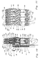
- FIGS. 3, 4, 10 and 12 it can be seen that in the preferred embodiment illustrated therein, all of the service and distribution clips 110, 72 are inserted into and retained in the connector module 26 from the same side.
- Distribution clips 72 shown on the base module 28 in FIG. 4 are provided only for illustrative purposes; these clips 72 are actually retained in the connector module 26.
- FIGS. 10 and 11 show barbs 156 on the clips 110, 72 which dig into the abutting surfaces of the connector module 26 to retain the clips 110, 72 therein.
- the IDCs 86, 116 are exposed to respective, opposite sides of the connector module 26 for attachment to respective lines. Same side assembly of the clips 110, 72 in the connector module 26 makes the connector module easier to assemble and easier to automate the assembly thereof, thus further increasing the efficiencies of the present invention.
- An important feature of the present invention is that it can be assembled without the need for any special tools.
- many prior art devices require the use of a specialized tool for the connection of lines to and assembly of terminal blocks.
- Prior art devices have profited from proprietary tools for terminal block assembly use.
- a service line is positioned in a bore 120 of the actuator 102 when the actuator is in an up position.
- the actuator 102 In the up position, the actuator 102 is disengaged from the IDC portion 116 of the clip 110.
- the line is retained in the bore 120.
- the actuator 102 is moved downwardly to engage the line in the slot 122 forming a conductive connection between the clip 110 and the line.
- the IDC portion 86 of the distribution clip 72 is engaged with a line.
- the distribution line is conductively coupled to the service line through the isolation legs 114, 112, respectively.
- An isolation port 124 is positioned over the spring biased connection of the isolation legs 112, 114. As shown in FIG. 9, an isolation plug 126 may be inserted through the isolation port 26 to separate the isolation arms 112, 114. With the arms 112, 114 separated by the isolation plug 126, the distribution line is disconnected from the service line. Further, test ports 128 are provided on top of the actuators 122 to provide a conductive path to contact the IDCs 116 positioned in the actuator 102. As such, test probes 130, 132 may be inserted into the test ports 128 to test the lines. It should be noted that the plug 126 does not have to be part of a test probe assembly 107, but may be an independent component which may be used in the absence of the test probes 130, 132.
- the distribution clip 72 and the service clip 110 are identical clips oriented in different direction so that the isolation legs 112, 114 are in engagement. Efficiencies gained in the present invention by use of identical parts is extended by the use of identical actuators 102 for the service connector assemblies 56 and the half-tap assemblies 60. This similarity of parts helps reduce the number of specialized parts required for the present invention which decreases problems which may be associated with additional unique components.
- the half-tap assembly 60 includes the actuator 102, the housing 104 and a pair of half-tap clips 136.
- Each clip 136 includes an insulation displacement connector portion 138, a forked connector portion 140 and a shaft 142 therebetween.
- the clips 136 are typically stamped from a desired metallic material.
- the half-tap clips 136 have a shaft 142 which is a twisted portion extending between the IDC portion 138 and the forked connector 140. This is desirable because this arrangement permits the half-tap clips 136 to be oriented in a direction which will allow engagement with the IDC 138 in the same orientation as the service connection assembly 56 while engaging a similarly aligned portion of the distribution clip 72.
- the forked connector 140 engages an aligned leg 144 of the distribution clip 72.
- Line 9-9 in FIG. 7 is offset slightly through a small portion of the assembly 20 in order to show in FIG. 9 the forked connector 140 coupled to the top portion of an aligned leg 144 of the corresponding distribution clip 72.
- a portion of a wall 145 has been broken away to reveal the connection therebehind.
- a half-tap assembly 60 can be connected to each of the distribution lines 52 to add a second line.
- the half-tap assembly 60 is connected to the connector module 26 by inserting the forked connector 140 through a corresponding access port 146 through the half-tap area 65 of the connector module 26.
- An upstanding pin 150 is also formed in this area for engaging a corresponding slot 152 formed in the half-tap housing 104.
- a rear wall 152 of the connector housing 104 is spaced away from a rear wall 154 of the service line assembly 56 to allow access to the isolation port 124 therebetween.
- the access ports 146 act as test probe points if the half-tap connector assembly 60 is not connected to the connector module 26.
- a half-tap assembly 60 is connected to the connector module 26, test access is provided by the test ports 128 formed through the actuator 102 of the half-tap assembly 60.
- the half-tap assembly 60 is easily attached or removed from the connector assembly in a pressed manner.
- the clips 136 are retained inside the housing 104 by means of barbs 156 formed on the outer perimeter of the clips 136.
- the clips 136 are inserted between slots 158 formed in the housing with the barbs 156 engaging the corresponding surface in the slots 158.
- the half-tap assembly 60 is provided as a single assembled component with captive elements thereof for attachment to and disengagement from the connector module 26.
- the actuator 102 is connected to the housing 104 and captively retained therein. Due to the modular nature of the half-tap assembly 60, the assemblies need only be attached when a second line is required and may be removed once a second line is no longer needed. This modular construction helps maintain only the connections that are needed and reduces the possibility for interconnection errors. Interconnection errors are reduced because the half-tap assembly 60 may be removed when no longer inserted thereby preventing an accidental connection thereto.
- the primary cavity 160 of the base module 28 and the connector cavities 100 of the connector module 26 may be filled with a non-conductive environmental protectant such as the "grease" in order to provide further environmental protection of the connections retained therein.
- a non-conductive environmental protectant such as the "grease"
- each of the actuators 102 employed in the service connection assemblies 56 and the half-tap assembly 60 may be provided with environmental protectant material in the bores 120 so as to provide a non-conductive environmental protectant around a connection between the lines and the corresponding IDC clips 116, 138, 86.
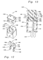
- the actuator 102 is shown in FIG. 13 in the raised position.
- the actuator 102 can be forced downwardly into the housing to engage a line retained in a bore 120 to engage the line with the IDC clip 138.
- the service connector assembly 56 and the half-tap assembly 60 include captivating means 162. While the half-tap assembly 60 is shown in FIG. 13, it should be understood that the same captivating means 162 may be employed with the service connection assembly 56.
- the captivating means 162 includes a protrusion 164, a captivating notch 166 and a engaging notch 168 which are positioned along a rearside of the actuator 169.
- the protrusion 164 extends into the captivating notch 166 to captively retain the actuator 102 in the housing 104.
- the protrusion 164 has a generally perpendicular edge surface 170 which abuts a corresponding generally perpendicular surface 172 of the captivating notch 166. When the surfaces 170, 172 abut, the actuator 102 is prevented from being disengaged from the housing 104.
- Both the engagement notch 168 and the captivating notch 166 have sloped surfaces 174, 176, respectively.
- the sloped surfaces 174, 176 allow the actuator 102 to travel upwardly and downwardly relative to the protrusion 164.
- the protrusion 164 has a sloped surface 178 which allows the sloped surface 176 of the captivating notch 166 to ride thereover when the actuator 102 is moved downwardly.
- the protrusion 164 engages the engagement notch 168.
- the generally perpendicular surface 170 on the protrusion 164 tends to resist disengagement of the protrusion 164 from the notch 168.
- the actuator 102 when suitable force is applied to the actuator 102, it can be upwardly disengaged from the housing 104 with the sloped surface 174 riding against the generally perpendicular surface 170 thereby allowing the actuator 102 to move upwardly.
- the engagement notch 168 allows the actuator 102 to be forcibly disengaged from the protrusion 164.
- the captivating notch 166 positively retains the actuator and prevents the actuator 102 from being disengaged from the protrusion 164 once the actuator 102 is positioned in the housing 104.
- the present invention includes a protection module 30.
- the protection module 30 includes a protection module housing 31 from which depends the rod mounting structure 36 and which include a plurality of chambers 186.
- each chamber is a ring clip 188 and a tip clip 190.
- the ring tip clip and the tip clip are also shown in FIG. 3 and include a forked connector 192 on one end of each clip 188, 190 and a gripper 194 formed on the opposite end of each clip 188, 190.
- the ring clip 188 and tip clip 190 are arranged so that the forked connectors 192 are axially aligned.
- FIG. 15 a partial fragmentary, perspective view of the underside of the protector module housing 31.
- This partial fragmentary, underside view is shown in order to illustrate the single piece, unitary construction of the housing 31 including the rod mounting structures 36 on the ends thereof.
- This single piece construction is advantageous because it eliminates numerous pieces and sub-assemblies as found in some prior art devices.
- the protection module 30 of the present invention has a single piece body for the housing 31.
- the single piece housing eliminates special, independent structures for mounting the module 30 to a rod frame system.
- the housing 31 includes a plurality of compartments 196 for retaining individual protector devices 198 (as shown in FIG. 3) which eliminates special independent cartridges or cassettes for holding protection devices. Additional efficiencies are gained from the single piece construction of the protection module housing 31 because additional parts are eliminated and a single type of housing 31 can be used regardless of the mounting frame system.
- the protector devices 198 as shown in FIG. 3 are three element gas tube type protector devices of a known construction. It is within the scope of the present invention to substitute two element protector devices, as well as solid state protectors in the protection module 30. These devices 198 are conductively coupled to the modular terminal block assembly system 20 of the present invention as set forth hereinabove.
- the protector devices 198 include three leads 200, 202, 204 which are engaged in corresponding grippers 194, 206, 194, respectively.
- the ground bar structure 48 includes a plurality of grippers 206 one each corresponding to a pair of ring clip and tip clip grippers 194.
- the lead 202 engages the ground bar gripper 206 and with the leads 200, 204 each, respectively, engaging a ring clip or tip clip gripper 194, 194.
- FIG. 17 the cross-sectional view taken along line 17-17 in FIG. 16 shows the engagement of the leads 200, 202, 204 with the corresponding grippers 194, 206, 194, respectively.
- FIG. 16 a partial fragmentary portion of the protection module 30 is shown with the ring clip 188, tip clip 190, as indicated by the grippers 194, and the ground bar 48 in position.
- a body portion 208 of the protection device 198 is retained in a corresponding compartment 196 with the body positioned against a wall 210 dividing compartment 196 into several portions.
- the secondary walls 212 are positioned between each protection device 198 so as to segregate or isolate the protection devices 198 from one another.
- the grounding bar structure 48 is constructed to be compatible with both the rod frame structure 22 and the u-shaped frame structure 24.
- the grounding bar 48 is a single piece component which is retained in the housing 31 having the biases portion 46 and the grippers 206 extending therefrom.
- the biased portion 46 biases against an outside surface 213 of the rod frame 22 or against the wall 50 of the u-shaped frame 24. In this manner, the biased portion maintains conductive contact with the conductive surface of the respective type of frame assembly. For example, if the assembly is attached to a U-shaped frame assembly, the biased portion 46 is forced inwardly by the dimensional difference of the spacing of the U-shaped frame mounting apertures and structures.
- the dimensional difference results in the biased portion 46 being biased outwardly against the wall 50.
- the biased portion is forced outwardly by the dimensional difference of the spacing of the rods and the rod mounting structures.
- the dimensional difference results in the biased portion 46 being biased inwardly against the rod surface 213.
- the protection module 30 of the present invention is positioned away from the connector module 26 to allow free access to the service connection assemblies 56 and the half-tap assemblies 60. In other words, connections may be made to and removed from the service connection assemblies 56 and any half-tap assemblies 60 while maintaining constant protection on the assembly 20.
- the present invention assures that tradespersons and equipment will be protected by the protection module 30 at all times.
- the present invention 20 is a modular design which allows the protection module 30 to be added after the distribution lines are connected to the base module 28 and the connector module 26. Further, the protection module 30 provides for removal of the protection devices 198 after a failure has occurred. This allows the fault to be corrected and a new protector 198 inserted into the corresponding compartment 196. The protection module 30 allows different types of protectors 198 to be inserted in order to retrofit an existing assembly 20 or other types of protection devices such as a solid state protection device 198.
Landscapes
- Engineering & Computer Science (AREA)
- Computer Networks & Wireless Communication (AREA)
- Connector Housings Or Holding Contact Members (AREA)
- Connections Arranged To Contact A Plurality Of Conductors (AREA)
Description
Claims (17)
- A modular terminal block assembly (20) for connecting at least one distribution line (52) to a corresponding service line (54), said modular terminal block assembly being characterized by:a base module (28) for dressing and retaining distribution lines;a connector module (26) having distribution clips (72) retained thereon for engagement with said distribution lines retained on said base module, and service clips (110) retained thereon for connection of service lines thereto, said service clips and distribution clips being conductively coupled.
- A modular terminal block assembly (20) as recited in Claim 1, being further characterized by:
a protection module (30) including protection grippers (194) retained thereon coupled to said distribution clips (72) retained on said connector module (26), protector devices (198) conductively coupled to said protection grippers for providing protection of corresponding ones of said distribution and service lines (52, 54) - A modular terminal block assembly (20) as recited in claim 2, being further characterized by:
said base module (28) having a first side (32) and a second side (34), said connector module (26) being attached to said first side of said base module, said protection module (30) being attached to said second side of said base module, said connector module and said base module retaining and conductively engaging distribution lines (52) therebetween and said connector module having service connection assemblies (56) attached thereto for conductively connecting said service lines (54) to said distribution lines (52). - A modular terminal block assembly (20) as recited in claim 3, being further characterized by:
said protection grippers (194) being positioned generally facing away from said second side (34) of said base module (28) for engaging a protector device (198) in a position spaced away from said service connection assemblies (56) to allow access to said service connection assemblies while maintaining line protection of said lines (52, 54) coupled to said modular terminal block assembly. - A modular terminal block assembly (20) as recited in claim 1, being further characterized by:an isolation leg (112, 114) connected to each of said service clips (110) and said distribution clips (72), at least one of said isolation legs (112, 114) providing structure; andisolation ports (124) in said connector module (26) proximate to said isolation legs (112, 114) of said service clips (110) and said distribution clips (72), said isolation ports being positioned for receiving a non-conductive body (126) therethrough for positioning between said isolation legs of said service clips and corresponding ones of said distribution clips to open the conductive connection formed thereby.
- A modular terminal block assembly (20) as recited in claim 1, being further characterized by:
a plurality of wire dressing structures (64) on a side of said base module (28) positioned for abutting and engaging said connector module (26). - A modular terminal block assembly (20) as recited in claim 6, being further characterized by:
said wire dressing structures (64) including a receiving channel (68) for orienting a line therein and a strain relief structure (82) positioned proximate to said receiving channel for retaining a portion of a line positioned in said receiving channel. - A modular terminal block assembly (20) as recited in claim 7, being further characterized by:
a connection well (76) formed in said base module (28) proximate to said receiving channel (68) for receiving a portion of said distribution clip (72) therein to connect a line positioned in said receiving channel extending over said connection well with said distribution clip. - A modular terminal block assembly (20) as recited in claim 7, being further characterized by:
a connection well (76) positioned proximate to said receiving channel (68) between said entry end (80) and said terminal end (74) for receiving a portion of a distribution clip (72) therein for connection to a line retained in said receiving channel (68), said strain relief structure (82) being positioned between said connection well and said terminal end of said line receiving channel. - A modular terminal block assembly (20) as recited in claim 9, being further characterized by:
a trimming structure (78) on said connector module (26) and a trimming cavity (76) positioned in said base module (28) proximate to said terminal end (74) of said receiving channel (68), said line trimming structure being positioned on said connector module for receipt in said trimming cavity for trimming a terminal end of a line retained in said receiving channel when attaching said connector module to said base module. - A modular terminal block assembly (20) as recited in claim 10, being further characterized by:
each of said trimming cavities (76) having a non-conductive material retained therein for environmentally protecting a trimmed portion of a line retained in said receiving channel (68). - A modular terminal block assembly (20) as recited in claim 1, being further characterized by:at least one half-tap assembly (60) attached to said connector module (26) proximate to a corresponding one of said service connection assemblies (56); andsaid half-tap assembly including half-tap clips (136) conductively connected to corresponding ones of said distribution clips (72) retained in said connector module for providing a second line connection associated with a corresponding service connection assembly.
- A modular terminal block assembly (20) as recited in claim 3, being further characterized by:
said base module (28) having locking fingers (66) formed on said first side thereof for engagement with an abutting portion of said connector module (26), and said protection module (30) including locking fingers for connection with said second side (34) of said base module. - A modular terminal block assembly (20) as recited in claim 2, being further characterized by:
a grounding structure (48) coupled to said protection module (30), said grounding structure comprising a unitary structure providing biased grounding contact (46) with a corresponding surface of one of a U-shaped frame mounting system (24) and a rod mounting system (22) to which said modular terminal block assembly is attached. - A modular terminal block assembly (20) as recited in claim 1, being further characterized by:a plurality of connection cavities (100) in said connector module (26), said service clips (110) extending into each of said connection cavities; anda connection actuator (102) sized and dimensioned for engagement in corresponding ones of said connection cavities; andmeans for captivating (162) said actuator in said cavity, said captivating means including retaining recesses (166,168) and a protrusion (164).
- A modular terminal block assembly (20) as recited in claim 15, being further characterized by:
a captivating notch (166) and an engagement notch (168) formed on said actuator (102) and said protrusion (164) formed on an inside surface of said connection cavity (100) for selectively engaging said engagement notch (168) and said captivating notch (166), said protrusion and said captivating notch being shaped for positively retaining said actuator in said connection cavity, said engagement notch and said captivating notch being shaped for allowing movement of said actuator relative to said connection cavity, whereby said protrusion holds said actuator in said connection cavity when engaged with said captivating notch and releasably retains said actuator in an engaged position when engaged with said engagement notch. - A modular terminal block assembly (20) as recited in claim 12, said half-tap assembly (60), being further characterized by:
means for captivating (162) a connection actuator (102) in a cavity (101), said captivating means including retaining recesses (166,168) and a protrusion (164), said captivating means having a captivating notch (166) and an engagement notch (168) formed on said actuator and said protrusion formed on an inside surface of said cavity for selectively engaging said engagement notch and said captivating notch, said protrusion and said captivating notch being shaped for positively retaining said actuator in said connection cavity, said engagement notch and said captivating notch being shaped for allowing movement of said actuator relative to said cavity, whereby said protrusion holds said actuator in said connection cavity when engaged with said captivating notch and releasably retains said actuator in an engaged position when engaged with said engagement notch.
Applications Claiming Priority (3)
| Application Number | Priority Date | Filing Date | Title |
|---|---|---|---|
| US08/536,062 US5779504A (en) | 1995-09-29 | 1995-09-29 | Modular terminal block assembly |
| US536062 | 1995-09-29 | ||
| PCT/US1996/015006 WO1997012423A1 (en) | 1995-09-29 | 1996-09-18 | Modular terminal block assembly |
Publications (3)
| Publication Number | Publication Date |
|---|---|
| EP0852827A1 EP0852827A1 (en) | 1998-07-15 |
| EP0852827A4 EP0852827A4 (en) | 1998-12-02 |
| EP0852827B1 true EP0852827B1 (en) | 2002-03-27 |
Family
ID=24136971
Family Applications (1)
| Application Number | Title | Priority Date | Filing Date |
|---|---|---|---|
| EP96935863A Expired - Lifetime EP0852827B1 (en) | 1995-09-29 | 1996-09-18 | Modular terminal block assembly |
Country Status (10)
| Country | Link |
|---|---|
| US (1) | US5779504A (en) |
| EP (1) | EP0852827B1 (en) |
| AR (1) | AR003721A1 (en) |
| AT (1) | ATE215271T1 (en) |
| AU (1) | AU699921B2 (en) |
| BR (1) | BR9610633A (en) |
| DE (1) | DE69620207D1 (en) |
| IL (1) | IL119285A (en) |
| NO (1) | NO980870L (en) |
| WO (1) | WO1997012423A1 (en) |
Families Citing this family (47)
| Publication number | Priority date | Publication date | Assignee | Title |
|---|---|---|---|---|
| USRE40150E1 (en) | 1994-04-25 | 2008-03-11 | Matsushita Electric Industrial Co., Ltd. | Fiber optic module |
| US5717533A (en) | 1995-01-13 | 1998-02-10 | Methode Electronics Inc. | Removable optoelectronic module |
| US6220878B1 (en) | 1995-10-04 | 2001-04-24 | Methode Electronics, Inc. | Optoelectronic module with grounding means |
| US5546281A (en) | 1995-01-13 | 1996-08-13 | Methode Electronics, Inc. | Removable optoelectronic transceiver module with potting box |
| SE505505C2 (en) * | 1995-02-10 | 1997-09-08 | Fatum Produkt Ab | Junction |
| SI9700205A (en) * | 1997-08-01 | 1999-04-30 | Elestra, D.O.O. | Terminal strip with attachment adapters |
| ES2141034B1 (en) * | 1998-01-15 | 2000-10-16 | Oberon Electronica S A | TELEPHONE TERMINAL. |
| US6056584A (en) * | 1998-03-19 | 2000-05-02 | Lucent Technologies Inc. | Dual sided insulation displacement connector block |
| US5989063A (en) * | 1998-03-30 | 1999-11-23 | Lucent Technologies Inc. | Splice chamber and connector assembly for a building entrance protector |
| AUPP308498A0 (en) | 1998-04-20 | 1998-05-14 | Krone Aktiengesellschaft | Electrical connector |
| US6179627B1 (en) | 1998-04-22 | 2001-01-30 | Stratos Lightwave, Inc. | High speed interface converter module |
| US6203333B1 (en) | 1998-04-22 | 2001-03-20 | Stratos Lightwave, Inc. | High speed interface converter module |
| US6530805B1 (en) * | 1998-07-20 | 2003-03-11 | International Business Machines Corporation | Contact pin holder assembly |
| US6196869B1 (en) * | 1998-10-30 | 2001-03-06 | Lucent Technologies Inc. | Mounting bracket and power bus for a connector block |
| US6093041A (en) * | 1998-10-30 | 2000-07-25 | Lucent Technologies Inc. | Connector block with internal power bus |
| DE19913097C1 (en) * | 1999-03-17 | 2000-07-06 | Krone Ag | Arrangement for holding e.g. telecommunications connecting strips has universal clip with holding elements with opening and slot for components for holding strip, and clip attachment elements |
| US7090509B1 (en) | 1999-06-11 | 2006-08-15 | Stratos International, Inc. | Multi-port pluggable transceiver (MPPT) with multiple LC duplex optical receptacles |
| KR100302524B1 (en) * | 1999-06-30 | 2001-11-01 | 이계철 | Protector module |
| KR100326803B1 (en) * | 1999-06-30 | 2002-03-04 | 이계철 | Terminal block |
| US6220873B1 (en) | 1999-08-10 | 2001-04-24 | Stratos Lightwave, Inc. | Modified contact traces for interface converter |
| JP3479769B2 (en) * | 2000-01-26 | 2003-12-15 | 日本航空電子工業株式会社 | Connector insertion / extraction mechanism |
| DE20001752U1 (en) * | 2000-02-01 | 2000-03-30 | Quante Ag, 42109 Wuppertal | Surge protection magazine and distribution facility for telecommunications technology |
| US6497592B1 (en) | 2000-02-16 | 2002-12-24 | Joshua Beadle | Voltage terminal connector assembly |
| KR100498147B1 (en) * | 2000-05-04 | 2005-07-01 | 대유통신 주식회사 | A idc type terminal protection base |
| DE20203912U1 (en) * | 2002-03-11 | 2003-07-17 | 3M Innovative Properties Co., St. Paul, Minn. | Connection module of telecommunications technology and combination with a connection module |
| US6814631B2 (en) | 2002-04-02 | 2004-11-09 | Marconi Intellectual Property (Ringfence) Inc. | Electrical terminal for surge protection cartridge |
| US6556411B1 (en) | 2002-04-02 | 2003-04-29 | Marconi Communications, Inc. | Purge protection cartridge with three-way attachment clip |
| US6997741B2 (en) * | 2003-11-15 | 2006-02-14 | Cray Inc. | Systems and methods for partitioning banks of processors in large computer systems |
| KR100576764B1 (en) | 2004-03-16 | 2006-05-10 | 전영찬 | IDC Telecom Block Support |
| US7011551B2 (en) * | 2004-05-06 | 2006-03-14 | Johansen Arnold W | Electrical terminal block |
| US7335049B2 (en) * | 2004-09-15 | 2008-02-26 | 3M Innovative Properties Company | Connector assembly for housing insulation displacement elements |
| US20060086530A1 (en) * | 2004-10-21 | 2006-04-27 | Robert Knabel | Wiring connector organizer |
| DE102005009856B4 (en) * | 2005-03-04 | 2008-10-09 | Rittal Gmbh & Co. Kg | Connection or device adapter |
| US20060264090A1 (en) * | 2005-05-18 | 2006-11-23 | Dower William V | Electrical connector assembly and method of forming the same |
| US7303446B2 (en) * | 2005-05-18 | 2007-12-04 | 3M Innovative Proprties Company | Frame assembly |
| US7503798B2 (en) * | 2005-06-03 | 2009-03-17 | Commscope, Inc. Of North Carolina | Cross connect systems with self-compensating balanced connector elements |
| US7223115B2 (en) * | 2005-06-03 | 2007-05-29 | Commscope, Inc. Of North Carolina | Cross-connect systems with connector blocks having balanced insulation displacement contacts |
| DE102008013317B4 (en) * | 2008-03-10 | 2010-10-14 | Adc Gmbh | Method for producing a wire connection strip with gel filling |
| US7985094B2 (en) * | 2008-09-15 | 2011-07-26 | Adc Gmbh | Connector block |
| DE102009024330A1 (en) * | 2009-06-09 | 2010-12-16 | Adc Gmbh | terminal block |
| FR2973956B1 (en) * | 2011-04-08 | 2013-03-22 | Nexans | DEVICE FOR CONNECTING DRIVER PAIRS |
| WO2013183011A2 (en) * | 2012-06-07 | 2013-12-12 | Intal Tech Ltd. | Electronic equipment building blocks for rack mounting |
| US8892034B2 (en) | 2012-06-26 | 2014-11-18 | Rosemount Inc. | Modular terminal assembly for wireless transmitters |
| WO2014119121A1 (en) * | 2013-02-01 | 2014-08-07 | シャープ株式会社 | Storage container |
| DE102013221820B3 (en) * | 2013-10-28 | 2014-07-10 | Tyco Electronics Amp Gmbh | Sign frame for use in distributer connection module for telecommunications and data processing technology, has connection arranged at bar end that is opposite to concave bulge, and connected with lower side of frame |
| US10524377B2 (en) | 2018-01-31 | 2019-12-31 | Eaton Intelligent Power Limited | Power distribution unit with interior busbars |
| US10665988B2 (en) * | 2018-08-08 | 2020-05-26 | Hyperframe Inc. | Framing assembly with modular connectors |
Family Cites Families (17)
| Publication number | Priority date | Publication date | Assignee | Title |
|---|---|---|---|---|
| AR208483A1 (en) * | 1975-11-10 | 1976-12-27 | Amp Inc | ELECTRICAL TERMINAL |
| DE3201894C1 (en) * | 1982-01-22 | 1983-06-09 | Krone Gmbh, 1000 Berlin | Modular terminal block |
| US4729064A (en) * | 1985-03-04 | 1988-03-01 | Adc Telecommunications, Inc. | Modular interconnect block with protector structure |
| US4652070A (en) * | 1985-10-18 | 1987-03-24 | Reliance Electric Company | Insulation displacement connector terminal block |
| DE3710896A1 (en) * | 1987-04-01 | 1988-10-20 | Krone Ag | DISTRIBUTION BOARD FOR TELECOMMUNICATION CABLES, IN PARTICULAR HOUSE ENTRANCE DISTRIBUTION BOARD |
| DE3726741C1 (en) * | 1987-08-07 | 1988-09-01 | Krone Ag | Terminal block of telecommunications technology |
| DE3902575C1 (en) * | 1989-01-26 | 1990-03-29 | Krone Ag, 1000 Berlin, De | |
| DE3917270C2 (en) * | 1989-05-23 | 1997-10-23 | Krone Ag | Terminal block with surge protection |
| EP0446572B1 (en) * | 1990-03-13 | 1995-01-11 | KRONE Aktiengesellschaft | Telecommunications and data systems engineering terminal block |
| FR2662042B1 (en) * | 1990-05-11 | 1994-03-18 | Sofycom | DEVICE FOR CONNECTING TELEPHONE LINES, THIS DEVICE INCLUDING AT LEAST ONE PLUG-IN MODULE FOR PROTECTION AGAINST OVERVOLTAGES. |
| US5147218A (en) * | 1991-04-12 | 1992-09-15 | Minnesota Mining And Manufacturing Company | Pluggable modular splicing connector and bridging adapter |
| US5127851A (en) * | 1991-07-25 | 1992-07-07 | Reliance Comm/Tec Corporation | Modular patch panel |
| US5178558A (en) * | 1991-09-23 | 1993-01-12 | Minnesota Mining And Manufacturing Company | Cross connect system for telecommunications systems |
| DE9300339U1 (en) * | 1993-01-09 | 1993-04-08 | Krone Ag, 14167 Berlin | Device for holding connection blocks for communication technology |
| US5302137A (en) * | 1993-04-22 | 1994-04-12 | Reliance Comm/Tec Corporation | Insulation displacement connector terminal block |
| US5451170A (en) * | 1993-09-28 | 1995-09-19 | Reliance Comm/Tec Corporation | Terminal block with protection |
| US5356309A (en) * | 1994-01-26 | 1994-10-18 | Porta Systems Corp. | Connector block with releasable mounting |
-
1995
- 1995-09-29 US US08/536,062 patent/US5779504A/en not_active Expired - Lifetime
-
1996
- 1996-09-18 WO PCT/US1996/015006 patent/WO1997012423A1/en not_active Ceased
- 1996-09-18 BR BR9610633-6A patent/BR9610633A/en not_active Application Discontinuation
- 1996-09-18 DE DE69620207T patent/DE69620207D1/en not_active Expired - Lifetime
- 1996-09-18 AT AT96935863T patent/ATE215271T1/en not_active IP Right Cessation
- 1996-09-18 AU AU73647/96A patent/AU699921B2/en not_active Ceased
- 1996-09-18 EP EP96935863A patent/EP0852827B1/en not_active Expired - Lifetime
- 1996-09-20 IL IL11928596A patent/IL119285A/en not_active IP Right Cessation
- 1996-09-25 AR ARP960104503A patent/AR003721A1/en unknown
-
1998
- 1998-02-27 NO NO980870A patent/NO980870L/en not_active Application Discontinuation
Also Published As
| Publication number | Publication date |
|---|---|
| BR9610633A (en) | 1999-12-21 |
| AR003721A1 (en) | 1998-09-09 |
| EP0852827A4 (en) | 1998-12-02 |
| ATE215271T1 (en) | 2002-04-15 |
| WO1997012423A1 (en) | 1997-04-03 |
| AU699921B2 (en) | 1998-12-17 |
| NO980870D0 (en) | 1998-02-27 |
| IL119285A (en) | 2000-01-31 |
| AU7364796A (en) | 1997-04-17 |
| IL119285A0 (en) | 1996-12-05 |
| EP0852827A1 (en) | 1998-07-15 |
| NO980870L (en) | 1998-03-27 |
| US5779504A (en) | 1998-07-14 |
| DE69620207D1 (en) | 2002-05-02 |
Similar Documents
| Publication | Publication Date | Title |
|---|---|---|
| US5779504A (en) | Modular terminal block assembly | |
| US5044981A (en) | Snap-on stacking telephone jack | |
| CA2112814C (en) | Telecommunications network interface assembly | |
| US4851967A (en) | Distribution bank for communication cables | |
| US4422706A (en) | Electrical connector plug with receptacle assembly | |
| WO1988005218A1 (en) | Filtered electrical device and method for making same | |
| US7241183B2 (en) | Electrical connector with integrated terminal position assurance and wire cover | |
| CA1216038A (en) | Multiple electrical connector and block with printed circuit board connector clip | |
| US5507653A (en) | Insulative wafers for interconnecting a vertical receptacle to a printed circuit board | |
| GB2287367A (en) | Transmission line connectors and assemblies thereof | |
| US4425019A (en) | Multiple electrical connector block with wire wrap pins | |
| US4611880A (en) | Multipiece electrical connector | |
| CA1242493A (en) | Connector for individual conductors and method for the wiring of a similar connector | |
| CA2229571C (en) | Modular terminal block assembly | |
| US4679880A (en) | Strain relief attachment for wire connector assembly | |
| CA1163000A (en) | Multiple electrical connector and block | |
| EP0185539B1 (en) | Guidance and retention device and connector assembly | |
| US4408820A (en) | Electrical terminals for modular wiring systems | |
| EP1241738B1 (en) | Electrical connector, particularly for vehicles | |
| JPS63245878A (en) | Multipair connector for cable | |
| US4904210A (en) | Telecommunications connector | |
| MXPA98001652A (en) | Modu terminal block assembly | |
| GB2293696A (en) | ID contact and connector for telecommunications | |
| US4558919A (en) | Multiple electrical connector and block having a back to back configuration | |
| CA2142131A1 (en) | Assembly of multi-terminal telecommunications connectors and terminals |
Legal Events
| Date | Code | Title | Description |
|---|---|---|---|
| PUAI | Public reference made under article 153(3) epc to a published international application that has entered the european phase |
Free format text: ORIGINAL CODE: 0009012 |
|
| 17P | Request for examination filed |
Effective date: 19980223 |
|
| AK | Designated contracting states |
Kind code of ref document: A1 Designated state(s): AT BE CH DE DK ES FI FR GB GR IE IT LI LU MC NL PT SE |
|
| A4 | Supplementary search report drawn up and despatched |
Effective date: 19981014 |
|
| AK | Designated contracting states |
Kind code of ref document: A4 Designated state(s): AT BE CH DE DK ES FI FR GB GR IE IT LI LU MC NL PT SE |
|
| 17Q | First examination report despatched |
Effective date: 20000120 |
|
| GRAG | Despatch of communication of intention to grant |
Free format text: ORIGINAL CODE: EPIDOS AGRA |
|
| RAP1 | Party data changed (applicant data changed or rights of an application transferred) |
Owner name: RELTEC CORPORATION |
|
| GRAG | Despatch of communication of intention to grant |
Free format text: ORIGINAL CODE: EPIDOS AGRA |
|
| GRAH | Despatch of communication of intention to grant a patent |
Free format text: ORIGINAL CODE: EPIDOS IGRA |
|
| RAP1 | Party data changed (applicant data changed or rights of an application transferred) |
Owner name: MARCONI COMMUNICATIONS, INC. |
|
| GRAH | Despatch of communication of intention to grant a patent |
Free format text: ORIGINAL CODE: EPIDOS IGRA |
|
| REG | Reference to a national code |
Ref country code: GB Ref legal event code: IF02 |
|
| GRAA | (expected) grant |
Free format text: ORIGINAL CODE: 0009210 |
|
| AK | Designated contracting states |
Kind code of ref document: B1 Designated state(s): AT BE CH DE DK ES FI FR GB GR IE IT LI LU MC NL PT SE |
|
| PG25 | Lapsed in a contracting state [announced via postgrant information from national office to epo] |
Ref country code: NL Free format text: LAPSE BECAUSE OF FAILURE TO SUBMIT A TRANSLATION OF THE DESCRIPTION OR TO PAY THE FEE WITHIN THE PRESCRIBED TIME-LIMIT Effective date: 20020327 Ref country code: LI Free format text: LAPSE BECAUSE OF FAILURE TO SUBMIT A TRANSLATION OF THE DESCRIPTION OR TO PAY THE FEE WITHIN THE PRESCRIBED TIME-LIMIT Effective date: 20020327 Ref country code: IT Free format text: LAPSE BECAUSE OF FAILURE TO SUBMIT A TRANSLATION OF THE DESCRIPTION OR TO PAY THE FEE WITHIN THE PRE;WARNING: LAPSES OF ITALIAN PATENTS WITH EFFECTIVE DATE BEFORE 2007 MAY HAVE OCCURRED AT ANY TIME BEFORE 2007. THE CORRECT EFFECTIVE DATE MAY BE DIFFERENT FROM THE ONE RECORDED.SCRIBED TIME-LIMIT Effective date: 20020327 Ref country code: GR Free format text: LAPSE BECAUSE OF FAILURE TO SUBMIT A TRANSLATION OF THE DESCRIPTION OR TO PAY THE FEE WITHIN THE PRESCRIBED TIME-LIMIT Effective date: 20020327 Ref country code: FR Free format text: LAPSE BECAUSE OF FAILURE TO SUBMIT A TRANSLATION OF THE DESCRIPTION OR TO PAY THE FEE WITHIN THE PRESCRIBED TIME-LIMIT Effective date: 20020327 Ref country code: FI Free format text: LAPSE BECAUSE OF FAILURE TO SUBMIT A TRANSLATION OF THE DESCRIPTION OR TO PAY THE FEE WITHIN THE PRESCRIBED TIME-LIMIT Effective date: 20020327 Ref country code: CH Free format text: LAPSE BECAUSE OF FAILURE TO SUBMIT A TRANSLATION OF THE DESCRIPTION OR TO PAY THE FEE WITHIN THE PRESCRIBED TIME-LIMIT Effective date: 20020327 Ref country code: BE Free format text: LAPSE BECAUSE OF FAILURE TO SUBMIT A TRANSLATION OF THE DESCRIPTION OR TO PAY THE FEE WITHIN THE PRESCRIBED TIME-LIMIT Effective date: 20020327 Ref country code: AT Free format text: LAPSE BECAUSE OF FAILURE TO SUBMIT A TRANSLATION OF THE DESCRIPTION OR TO PAY THE FEE WITHIN THE PRESCRIBED TIME-LIMIT Effective date: 20020327 |
|
| REF | Corresponds to: |
Ref document number: 215271 Country of ref document: AT Date of ref document: 20020415 Kind code of ref document: T |
|
| REG | Reference to a national code |
Ref country code: CH Ref legal event code: EP |
|
| REF | Corresponds to: |
Ref document number: 69620207 Country of ref document: DE Date of ref document: 20020502 |
|
| REG | Reference to a national code |
Ref country code: IE Ref legal event code: FG4D |
|
| PG25 | Lapsed in a contracting state [announced via postgrant information from national office to epo] |
Ref country code: PT Free format text: LAPSE BECAUSE OF FAILURE TO SUBMIT A TRANSLATION OF THE DESCRIPTION OR TO PAY THE FEE WITHIN THE PRESCRIBED TIME-LIMIT Effective date: 20020627 Ref country code: DK Free format text: LAPSE BECAUSE OF FAILURE TO SUBMIT A TRANSLATION OF THE DESCRIPTION OR TO PAY THE FEE WITHIN THE PRESCRIBED TIME-LIMIT Effective date: 20020627 |
|
| PG25 | Lapsed in a contracting state [announced via postgrant information from national office to epo] |
Ref country code: DE Free format text: LAPSE BECAUSE OF FAILURE TO SUBMIT A TRANSLATION OF THE DESCRIPTION OR TO PAY THE FEE WITHIN THE PRESCRIBED TIME-LIMIT Effective date: 20020628 |
|
| NLV1 | Nl: lapsed or annulled due to failure to fulfill the requirements of art. 29p and 29m of the patents act | ||
| PG25 | Lapsed in a contracting state [announced via postgrant information from national office to epo] |
Ref country code: LU Free format text: LAPSE BECAUSE OF NON-PAYMENT OF DUE FEES Effective date: 20020918 Ref country code: IE Free format text: LAPSE BECAUSE OF NON-PAYMENT OF DUE FEES Effective date: 20020918 |
|
| PG25 | Lapsed in a contracting state [announced via postgrant information from national office to epo] |
Ref country code: ES Free format text: LAPSE BECAUSE OF FAILURE TO SUBMIT A TRANSLATION OF THE DESCRIPTION OR TO PAY THE FEE WITHIN THE PRESCRIBED TIME-LIMIT Effective date: 20020925 |
|
| REG | Reference to a national code |
Ref country code: CH Ref legal event code: PL |
|
| EN | Fr: translation not filed | ||
| PLBE | No opposition filed within time limit |
Free format text: ORIGINAL CODE: 0009261 |
|
| STAA | Information on the status of an ep patent application or granted ep patent |
Free format text: STATUS: NO OPPOSITION FILED WITHIN TIME LIMIT |
|
| 26N | No opposition filed |
Effective date: 20021230 |
|
| PG25 | Lapsed in a contracting state [announced via postgrant information from national office to epo] |
Ref country code: MC Free format text: LAPSE BECAUSE OF NON-PAYMENT OF DUE FEES Effective date: 20030401 |
|
| REG | Reference to a national code |
Ref country code: IE Ref legal event code: MM4A |
|
| REG | Reference to a national code |
Ref country code: GB Ref legal event code: 732E |
|
| PGFP | Annual fee paid to national office [announced via postgrant information from national office to epo] |
Ref country code: SE Payment date: 20040928 Year of fee payment: 9 |
|
| PG25 | Lapsed in a contracting state [announced via postgrant information from national office to epo] |
Ref country code: SE Free format text: LAPSE BECAUSE OF NON-PAYMENT OF DUE FEES Effective date: 20050919 |
|
| REG | Reference to a national code |
Ref country code: GB Ref legal event code: 732E |
|
| EUG | Se: european patent has lapsed | ||
| PGFP | Annual fee paid to national office [announced via postgrant information from national office to epo] |
Ref country code: GB Payment date: 20110926 Year of fee payment: 16 |
|
| GBPC | Gb: european patent ceased through non-payment of renewal fee |
Effective date: 20120918 |
|
| PG25 | Lapsed in a contracting state [announced via postgrant information from national office to epo] |
Ref country code: GB Free format text: LAPSE BECAUSE OF NON-PAYMENT OF DUE FEES Effective date: 20120918 |