EP0852272B1 - Recovery process in a pulp mill - Google Patents
Recovery process in a pulp mill Download PDFInfo
- Publication number
- EP0852272B1 EP0852272B1 EP97203861A EP97203861A EP0852272B1 EP 0852272 B1 EP0852272 B1 EP 0852272B1 EP 97203861 A EP97203861 A EP 97203861A EP 97203861 A EP97203861 A EP 97203861A EP 0852272 B1 EP0852272 B1 EP 0852272B1
- Authority
- EP
- European Patent Office
- Prior art keywords
- potassium
- solution
- ion exchange
- precipitator dust
- chloride
- Prior art date
- Legal status (The legal status is an assumption and is not a legal conclusion. Google has not performed a legal analysis and makes no representation as to the accuracy of the status listed.)
- Expired - Lifetime
Links
- 238000011084 recovery Methods 0.000 title claims abstract description 39
- 229910052700 potassium Inorganic materials 0.000 claims abstract description 82
- ZLMJMSJWJFRBEC-UHFFFAOYSA-N Potassium Chemical compound [K] ZLMJMSJWJFRBEC-UHFFFAOYSA-N 0.000 claims abstract description 77
- 239000011591 potassium Substances 0.000 claims abstract description 77
- 239000000428 dust Substances 0.000 claims abstract description 59
- 239000012716 precipitator Substances 0.000 claims abstract description 49
- 238000005342 ion exchange Methods 0.000 claims abstract description 45
- 238000000034 method Methods 0.000 claims abstract description 37
- VEXZGXHMUGYJMC-UHFFFAOYSA-M Chloride anion Chemical compound [Cl-] VEXZGXHMUGYJMC-UHFFFAOYSA-M 0.000 claims abstract description 32
- 239000000126 substance Substances 0.000 claims abstract description 24
- 239000000463 material Substances 0.000 claims abstract description 22
- 229910001410 inorganic ion Inorganic materials 0.000 claims abstract description 20
- 238000004537 pulping Methods 0.000 claims abstract description 16
- 238000011282 treatment Methods 0.000 claims abstract description 15
- 239000007788 liquid Substances 0.000 claims abstract description 11
- 229910001414 potassium ion Inorganic materials 0.000 claims abstract description 6
- PMZURENOXWZQFD-UHFFFAOYSA-L Sodium Sulfate Chemical compound [Na+].[Na+].[O-]S([O-])(=O)=O PMZURENOXWZQFD-UHFFFAOYSA-L 0.000 claims description 27
- 229910052938 sodium sulfate Inorganic materials 0.000 claims description 14
- 229910052680 mordenite Inorganic materials 0.000 claims description 12
- 235000011152 sodium sulphate Nutrition 0.000 claims description 12
- 238000000909 electrodialysis Methods 0.000 claims description 10
- 239000012452 mother liquor Substances 0.000 claims description 7
- 238000002386 leaching Methods 0.000 claims description 6
- 238000001953 recrystallisation Methods 0.000 claims description 4
- 239000002245 particle Substances 0.000 abstract description 3
- 239000000243 solution Substances 0.000 description 62
- 239000010457 zeolite Substances 0.000 description 27
- HNPSIPDUKPIQMN-UHFFFAOYSA-N dioxosilane;oxo(oxoalumanyloxy)alumane Chemical compound O=[Si]=O.O=[Al]O[Al]=O HNPSIPDUKPIQMN-UHFFFAOYSA-N 0.000 description 26
- 229910021536 Zeolite Inorganic materials 0.000 description 23
- 239000011734 sodium Substances 0.000 description 22
- 229910052708 sodium Inorganic materials 0.000 description 20
- DGAQECJNVWCQMB-PUAWFVPOSA-M Ilexoside XXIX Chemical compound C[C@@H]1CC[C@@]2(CC[C@@]3(C(=CC[C@H]4[C@]3(CC[C@@H]5[C@@]4(CC[C@@H](C5(C)C)OS(=O)(=O)[O-])C)C)[C@@H]2[C@]1(C)O)C)C(=O)O[C@H]6[C@@H]([C@H]([C@@H]([C@H](O6)CO)O)O)O.[Na+] DGAQECJNVWCQMB-PUAWFVPOSA-M 0.000 description 19
- XLYOFNOQVPJJNP-UHFFFAOYSA-N water Substances O XLYOFNOQVPJJNP-UHFFFAOYSA-N 0.000 description 17
- 229910021653 sulphate ion Inorganic materials 0.000 description 13
- QAOWNCQODCNURD-UHFFFAOYSA-L Sulfate Chemical compound [O-]S([O-])(=O)=O QAOWNCQODCNURD-UHFFFAOYSA-L 0.000 description 11
- 150000002500 ions Chemical class 0.000 description 11
- 238000010411 cooking Methods 0.000 description 10
- 239000000706 filtrate Substances 0.000 description 8
- 239000012528 membrane Substances 0.000 description 8
- HEMHJVSKTPXQMS-UHFFFAOYSA-M Sodium hydroxide Chemical compound [OH-].[Na+] HEMHJVSKTPXQMS-UHFFFAOYSA-M 0.000 description 6
- 229920001429 chelating resin Polymers 0.000 description 6
- 238000004519 manufacturing process Methods 0.000 description 6
- CDBYLPFSWZWCQE-UHFFFAOYSA-L Sodium Carbonate Chemical compound [Na+].[Na+].[O-]C([O-])=O CDBYLPFSWZWCQE-UHFFFAOYSA-L 0.000 description 5
- 229910052783 alkali metal Inorganic materials 0.000 description 5
- 150000001340 alkali metals Chemical class 0.000 description 5
- 238000002474 experimental method Methods 0.000 description 5
- 239000002655 kraft paper Substances 0.000 description 5
- 230000008929 regeneration Effects 0.000 description 5
- 238000011069 regeneration method Methods 0.000 description 5
- QAOWNCQODCNURD-UHFFFAOYSA-N Sulfuric acid Chemical compound OS(O)(=O)=O QAOWNCQODCNURD-UHFFFAOYSA-N 0.000 description 4
- 239000007864 aqueous solution Substances 0.000 description 4
- 239000012141 concentrate Substances 0.000 description 4
- 239000013078 crystal Substances 0.000 description 4
- OSVXSBDYLRYLIG-UHFFFAOYSA-N dioxidochlorine(.) Chemical compound O=Cl=O OSVXSBDYLRYLIG-UHFFFAOYSA-N 0.000 description 4
- 239000000123 paper Substances 0.000 description 4
- 238000010926 purge Methods 0.000 description 4
- 238000000926 separation method Methods 0.000 description 4
- 238000012360 testing method Methods 0.000 description 4
- BVKZGUZCCUSVTD-UHFFFAOYSA-L Carbonate Chemical compound [O-]C([O-])=O BVKZGUZCCUSVTD-UHFFFAOYSA-L 0.000 description 3
- 229920001131 Pulp (paper) Polymers 0.000 description 3
- NINIDFKCEFEMDL-UHFFFAOYSA-N Sulfur Chemical compound [S] NINIDFKCEFEMDL-UHFFFAOYSA-N 0.000 description 3
- 239000005864 Sulphur Substances 0.000 description 3
- 238000004458 analytical method Methods 0.000 description 3
- 150000001450 anions Chemical class 0.000 description 3
- 239000002585 base Substances 0.000 description 3
- 239000007844 bleaching agent Substances 0.000 description 3
- 239000000460 chlorine Substances 0.000 description 3
- 238000005868 electrolysis reaction Methods 0.000 description 3
- 239000007789 gas Substances 0.000 description 3
- 229910052751 metal Inorganic materials 0.000 description 3
- 239000002184 metal Substances 0.000 description 3
- 150000002739 metals Chemical class 0.000 description 3
- 238000000197 pyrolysis Methods 0.000 description 3
- 239000002002 slurry Substances 0.000 description 3
- LSNNMFCWUKXFEE-UHFFFAOYSA-L sulfite Chemical compound [O-]S([O-])=O LSNNMFCWUKXFEE-UHFFFAOYSA-L 0.000 description 3
- 239000002023 wood Substances 0.000 description 3
- NLXLAEXVIDQMFP-UHFFFAOYSA-N Ammonia chloride Chemical compound [NH4+].[Cl-] NLXLAEXVIDQMFP-UHFFFAOYSA-N 0.000 description 2
- QGZKDVFQNNGYKY-UHFFFAOYSA-O Ammonium Chemical compound [NH4+] QGZKDVFQNNGYKY-UHFFFAOYSA-O 0.000 description 2
- OKTJSMMVPCPJKN-UHFFFAOYSA-N Carbon Chemical compound [C] OKTJSMMVPCPJKN-UHFFFAOYSA-N 0.000 description 2
- 239000004155 Chlorine dioxide Substances 0.000 description 2
- VEXZGXHMUGYJMC-UHFFFAOYSA-N Hydrochloric acid Chemical compound Cl VEXZGXHMUGYJMC-UHFFFAOYSA-N 0.000 description 2
- 239000007832 Na2SO4 Substances 0.000 description 2
- FAPWRFPIFSIZLT-UHFFFAOYSA-M Sodium chloride Chemical compound [Na+].[Cl-] FAPWRFPIFSIZLT-UHFFFAOYSA-M 0.000 description 2
- 238000004364 calculation method Methods 0.000 description 2
- 150000001768 cations Chemical class 0.000 description 2
- 229910052801 chlorine Inorganic materials 0.000 description 2
- 235000019398 chlorine dioxide Nutrition 0.000 description 2
- 239000012527 feed solution Substances 0.000 description 2
- 238000001914 filtration Methods 0.000 description 2
- 239000008187 granular material Substances 0.000 description 2
- 239000012535 impurity Substances 0.000 description 2
- 238000013508 migration Methods 0.000 description 2
- 230000005012 migration Effects 0.000 description 2
- 238000002156 mixing Methods 0.000 description 2
- 239000000203 mixture Substances 0.000 description 2
- BWHMMNNQKKPAPP-UHFFFAOYSA-L potassium carbonate Chemical compound [K+].[K+].[O-]C([O-])=O BWHMMNNQKKPAPP-UHFFFAOYSA-L 0.000 description 2
- 159000000001 potassium salts Chemical class 0.000 description 2
- OTYBMLCTZGSZBG-UHFFFAOYSA-L potassium sulfate Chemical compound [K+].[K+].[O-]S([O-])(=O)=O OTYBMLCTZGSZBG-UHFFFAOYSA-L 0.000 description 2
- 229910052939 potassium sulfate Inorganic materials 0.000 description 2
- 239000000843 powder Substances 0.000 description 2
- 239000000047 product Substances 0.000 description 2
- 239000002994 raw material Substances 0.000 description 2
- 229920005989 resin Polymers 0.000 description 2
- 239000011347 resin Substances 0.000 description 2
- 239000007787 solid Substances 0.000 description 2
- 238000003756 stirring Methods 0.000 description 2
- -1 sulphate ions Chemical class 0.000 description 2
- 238000005406 washing Methods 0.000 description 2
- ZAMOUSCENKQFHK-UHFFFAOYSA-N Chlorine atom Chemical compound [Cl] ZAMOUSCENKQFHK-UHFFFAOYSA-N 0.000 description 1
- 229910017917 NH4 Cl Inorganic materials 0.000 description 1
- 239000004677 Nylon Substances 0.000 description 1
- NPYPAHLBTDXSSS-UHFFFAOYSA-N Potassium ion Chemical group [K+] NPYPAHLBTDXSSS-UHFFFAOYSA-N 0.000 description 1
- 238000000862 absorption spectrum Methods 0.000 description 1
- 239000002253 acid Substances 0.000 description 1
- QVGXLLKOCUKJST-UHFFFAOYSA-N atomic oxygen Chemical compound [O] QVGXLLKOCUKJST-UHFFFAOYSA-N 0.000 description 1
- 239000012267 brine Substances 0.000 description 1
- 229910052791 calcium Inorganic materials 0.000 description 1
- 229910052799 carbon Inorganic materials 0.000 description 1
- 238000005341 cation exchange Methods 0.000 description 1
- 125000002091 cationic group Chemical group 0.000 description 1
- 238000005119 centrifugation Methods 0.000 description 1
- 238000006243 chemical reaction Methods 0.000 description 1
- 238000002485 combustion reaction Methods 0.000 description 1
- 230000000052 comparative effect Effects 0.000 description 1
- 238000007796 conventional method Methods 0.000 description 1
- 230000007797 corrosion Effects 0.000 description 1
- 238000005260 corrosion Methods 0.000 description 1
- 238000000354 decomposition reaction Methods 0.000 description 1
- 238000010586 diagram Methods 0.000 description 1
- 238000010790 dilution Methods 0.000 description 1
- 239000012895 dilution Substances 0.000 description 1
- 238000004090 dissolution Methods 0.000 description 1
- 230000005684 electric field Effects 0.000 description 1
- 239000003792 electrolyte Substances 0.000 description 1
- 239000012717 electrostatic precipitator Substances 0.000 description 1
- 230000007613 environmental effect Effects 0.000 description 1
- 239000012065 filter cake Substances 0.000 description 1
- 239000013505 freshwater Substances 0.000 description 1
- 239000011521 glass Substances 0.000 description 1
- 239000011121 hardwood Substances 0.000 description 1
- 229930195733 hydrocarbon Natural products 0.000 description 1
- 150000002430 hydrocarbons Chemical class 0.000 description 1
- 229910010272 inorganic material Inorganic materials 0.000 description 1
- 239000011147 inorganic material Substances 0.000 description 1
- 239000003456 ion exchange resin Substances 0.000 description 1
- 229920003303 ion-exchange polymer Polymers 0.000 description 1
- 229910052742 iron Inorganic materials 0.000 description 1
- 229920005610 lignin Polymers 0.000 description 1
- 229910052749 magnesium Inorganic materials 0.000 description 1
- 229910052748 manganese Inorganic materials 0.000 description 1
- 229910021645 metal ion Inorganic materials 0.000 description 1
- 239000011259 mixed solution Substances 0.000 description 1
- 229910052750 molybdenum Inorganic materials 0.000 description 1
- 229920001778 nylon Polymers 0.000 description 1
- 239000011368 organic material Substances 0.000 description 1
- 239000001301 oxygen Substances 0.000 description 1
- 229910052760 oxygen Inorganic materials 0.000 description 1
- 239000008188 pellet Substances 0.000 description 1
- 239000012071 phase Substances 0.000 description 1
- 229910052698 phosphorus Inorganic materials 0.000 description 1
- 239000011148 porous material Substances 0.000 description 1
- 229910000027 potassium carbonate Inorganic materials 0.000 description 1
- 150000003112 potassium compounds Chemical class 0.000 description 1
- 238000000746 purification Methods 0.000 description 1
- 230000001172 regenerating effect Effects 0.000 description 1
- 229920006395 saturated elastomer Polymers 0.000 description 1
- 239000012047 saturated solution Substances 0.000 description 1
- 239000013535 sea water Substances 0.000 description 1
- 238000004062 sedimentation Methods 0.000 description 1
- 229910052710 silicon Inorganic materials 0.000 description 1
- 229910000342 sodium bisulfate Inorganic materials 0.000 description 1
- WBHQBSYUUJJSRZ-UHFFFAOYSA-M sodium bisulfate Chemical compound [Na+].OS([O-])(=O)=O WBHQBSYUUJJSRZ-UHFFFAOYSA-M 0.000 description 1
- 229910000029 sodium carbonate Inorganic materials 0.000 description 1
- 239000011780 sodium chloride Substances 0.000 description 1
- HPALAKNZSZLMCH-UHFFFAOYSA-M sodium;chloride;hydrate Chemical compound O.[Na+].[Cl-] HPALAKNZSZLMCH-UHFFFAOYSA-M 0.000 description 1
- 239000011122 softwood Substances 0.000 description 1
- 239000011343 solid material Substances 0.000 description 1
- 239000007790 solid phase Substances 0.000 description 1
- 238000010977 unit operation Methods 0.000 description 1
- 238000004065 wastewater treatment Methods 0.000 description 1
- 229910052725 zinc Inorganic materials 0.000 description 1
Images
Classifications
-
- D—TEXTILES; PAPER
- D21—PAPER-MAKING; PRODUCTION OF CELLULOSE
- D21C—PRODUCTION OF CELLULOSE BY REMOVING NON-CELLULOSE SUBSTANCES FROM CELLULOSE-CONTAINING MATERIALS; REGENERATION OF PULPING LIQUORS; APPARATUS THEREFOR
- D21C11/00—Regeneration of pulp liquors or effluent waste waters
- D21C11/0042—Fractionating or concentration of spent liquors by special methods
- D21C11/005—Treatment of liquors with ion-exchangers
-
- D—TEXTILES; PAPER
- D21—PAPER-MAKING; PRODUCTION OF CELLULOSE
- D21C—PRODUCTION OF CELLULOSE BY REMOVING NON-CELLULOSE SUBSTANCES FROM CELLULOSE-CONTAINING MATERIALS; REGENERATION OF PULPING LIQUORS; APPARATUS THEREFOR
- D21C11/00—Regeneration of pulp liquors or effluent waste waters
- D21C11/06—Treatment of pulp gases; Recovery of the heat content of the gases; Treatment of gases arising from various sources in pulp and paper mills; Regeneration of gaseous SO2, e.g. arising from liquors containing sulfur compounds
- D21C11/063—Treatment of gas streams comprising solid matter, e.g. the ashes resulting from the combustion of black liquor
- D21C11/066—Separation of solid compounds from these gases; further treatment of recovered products
Definitions
- the present invention relates to an environmental-friendly process for reducing the content of potassium ions in a liquid inventory of a chemical pulp mill.
- chips of lignocellulose-containing material are cooked in an alkaline or acid aqueous solution.
- This cooking liquid contains inorganic pulping chemicals to improve the dissolution of lignin.
- the cooking is normally carried out at a temperature above 100°C to reduce the residence time for the pulp produced. Therefore, the cooking is carried out in a pressure vessel known as a digester.
- An essential part of the recovery system is the recovery boiler, where the spent liquor is burned. Normally, make-up chemicals are added to the spent liquor before the recovery boiler to make up for the chemicals lost during cooking and recovery.
- the spent liquor is sprayed into the lower part of the boiler, previously at a relatively low temperature to remove free water.
- Modern recovery boilers operate at a high temperature to reduce the content of sulphur in the flow gases leaving the boiler. Higher up in the boiler, gases and vapours of light hydrocarbons and decomposition products are volatilized. This is known as pyrolysis. Then, the pyrolysis products are burned after mixing with air or oxygen.
- the solid carbon-based residue which remains after complete pyrolysis of the organics is then heterogeneously burned.
- the solid particles formed are collected as a dust in precipitators at the top of the recovery boiler, to reduce the release of solid material to the surrounding atmosphere.
- chloride and potassium in the spent liquor entering the recovery boiler. These elements tend to reduce the capacity of the recovery boiler to produce useful chemicals. Thus, chloride and potassium increase the stickiness of carryover deposits and dust particles to the recovery boiler tubes, which accelerate fouling and plugging in the upper part of the recovery boiler. Chloride also tend to increase the corrosion rate of superheater tubes.
- Chloride and potassium are concentrated in the dust formed during the combustion of spent liquor in the recovery boiler.
- the dust is collected in dry-bottom or wet-bottom electrostatic precipitators.
- the dust mainly consists of sodium and potassium salts, where sulphate, carbonate and chloride are the dominant anions.
- the amount of dust corresponds to from about 5 up to about 15% by weight of the sodium entering the recovery boiler, which corresponds to from about 50 up to about 150 kg dust per tonne pulp, if the dust is calculated as sodium sulphate.
- the largest source of potassium is the wood, and the intake will depend on the wood source generally varying from about 0,5 to 5 kg per tonne pulp.
- the hardwood species usually contains larger amounts of potassium than softwood species.
- the content of chloride in the spent liquor can be very high for coastal mills, if the raw material consists of logs floated in seawater. As the environmental legislation becomes more stringent regarding pulp mill discharges to air and water, the degree of system closure increases. This means that even a small input of chloride and potassium becomes a severe problem, unless the content can be controlled by purging the system in some environmentally acceptable way.
- Chloride and potassium removal are preferably carried out in a common waste water treatment. Chloride can be removed efficiently by e.g. electrodialysis, while potassium still is difficult to remove efficiently electrochemically.
- WO-A1-9404747 discloses a process, in which the content of potassium and chloride in a recovery system for pulping chemicals can be reduced.
- the process comprises collecting precipitator dust, dissolving the dust in water to produce an aqueous solution of precipitator dust, whereupon said aqueous solution is electrolysed in a cell for production of chlorine or hydrochloric acid in the anolyte.
- Use of ion exchange is suggested as a pretreatment before the electrolyses, chiefly to remove divalent ions such as Ca 2+ and Mg2+.
- the membrane used in the electrochemical cell can be of an inorganic ion-exchange type.
- the present invention relates to a process according to claim 1 by which the content of potassium ions in a recovery system for pulping chemicals can be reduced.
- An advantage of the present process is the possibility to reduce the content of potassium in the liquid inventory and more particularly in the spent liquor entering the recovery boiler.
- the problem of sticky deposits in the recovery boiler can be substantially reduced. This means an improved energy efficiency as well as a higher degree of recovery of the pulping chemicals.
- the present invention can be used in the production of a chemical pulp and especially for production of a sulphate pulp, soda pulp or sulphite pulp with an alkali metal as base.
- a kraft pulp is a special type of sulphate pulp, where the pulp is under-cooked to produce a dark-coloured pulp of exceptional strength.
- the present invention can also be used in the production of sulphate, soda or sulphite pulps with an alkali metal as base, where the cooking processes have been modified, combined or extended compared to the normal pulping techniques.
- the present process is applied where the recovery system for pulping chemicals is a kraft recovery system.
- a liquid inventory is the total quantity of various liquids in a mill, with varying contents of active or activatable cooking liquid components.
- the liquid inventory of a sulphate mill mainly consists of white liquor, black liquor, green liquor and spent liquor entering the recovery boiler.
- the spent liquor to be burned in the present process is a used cooking liquid withdrawn from a digester, optionally with added make-up chemicals. Potassium and sodium are alkali metals present in the spent liquors.
- the amount of precipitator dust formed depends mainly on the temperature in the boiler, the ratio between sodium and sulphur in the spent liquor and the raw material and sulphidity of the cooking process. A high temperature in the lower part of the boiler to reduce the sulphur content in the flow gases, increases the amount of dust formed.
- composition of precipitator dust formed in recovery boilers vary considerably depending on type and origin of wood, cooking process, purity of make-up chemicals, temperature in the boiler, type of precipitator etc. However, irrespective of these factors the dust mainly consists of sodium and potassium salts, where sulphate, carbonate and chloride are the dominant anions.
- a typical composition of precipitator dust from a kraft recovery system is Na 2 SO 4 80-85% by weight, Na 2 CO 3 2-8% by weight, NaCI 2-8% by weight, NaHSO 4 + Na 2 S 2 O 7 ⁇ 2% by weight, K 2 SO 4 5-10% by weight, K 2 CO 3 0.5-1% by weight, KCI ⁇ 1% by weight, metal ions such as Ca, Fe, Mg, P, Si, Mn, Zn, Mo ⁇ 1% by weight and organic material ⁇ 1 % by weight.
- a suitable zeolite used in the present invention is mordenite, exemplified by Sodium Mordenite EM120 manufactured by Eka Chemicals AB.
- the amount of inorganic ion exchange material used is based upon the ion exchange capacity of the actual inorganic material and the amount of potassium in the precipitator dust.
- the inorganic ion exchange material is preferably used in excess of the stoicheometric amount of potassium.
- the potassium and chloride containing solution is treated with an inorganic ion exchange material.
- the ion exchanged material, enriched on potassium is then preferably filtered and washed with water, whereafter the spent ion exchanger material can be deposited in a land fill.
- the solution depleted on potassium and chloride can be recycled in the pulp mill or forwarded to another step in the treatment of precipitator dust for mixing or dilution.
- the separation and washing can preferably take place in a centrifuge, a filter press or a vacuum filter.
- a sodium rich aqueous solution This could for example be a solution of the Na 2 SO 4 salt cake obtained from a chlorine dioxide generator (or from a crystallisator, or a chloride concentrate from an electrochemical cell). Separation, washing, regeneration and dewatering then may take place in the same piece of equipment operating in a continuos mode. Even the ion exchange may take place in the separation equipment. This can be done batchwise in a filter press or continuos eg. in a centrifuge or a rotating filter of vacuum or pressure type.
- the inorganic ion exchange material is made in the form of granules or pellets and are placed as a fixed bed in a column, thus forming an ion exchanger.
- the precipitator dust solution, rich on potassium is forced to flow through the bed of ion exchange material to which the potassium is adsorbed.
- the reaction zone proceeds down the column as the upper layers of ion exchange material reaches equilibrium with the solution.
- the ion exchange material is backwashed (regenerated) with a sodium electrolyte.
- the flow of potassium rich solution is simultaneously switched to another column.
- a number of columns can be arranged in parallel so that the continuos operation is ensured.
- the advantage with this embodiment, columns arranged in parallel, over the previously described is that the operation is continuous and that a more efficient ion exchange can be achieved as multiple equilibrium stages are obtained (cf. McKabe-Thiele diagram).
- the amount potassium removed in a precipitator dust solution subjected to a treatment with an inorganic ion exchange material can be above about 40 %, suitably above about 50 %, preferably above about 60 % and most preferred above about 70 %.
- a potassium free or potassium depleted stream which has undergone the inorganic ion exchange, is preferably recycled to the weak black liquor or may, in the cases where the water balance allows, be mixed with the strong black liquor and fed directly into the recovery boiler in the recovery system.
- a solution of precipitator dust will also commonly have a pH between about 7 and about 11, within which range most ion exchange material are stable and thus preferred.
- the pH is not critical since many ion exchange material work satisfactory outside the pH range 7-11.
- the ion exchange is suitably performed in the range from above 0°C up to about 100°C and preferably from about 20°C up to about 60°C.
- the residence time for the suitable batchwise ion exchange is preferably at least about 1 minute.
- the residence time is at least about 1 hour, preferably at least about 2 hours and most preferred at least about 5 hours.
- the upper residence time is not critical, but have to be set by process-technical reasons.
- the flow rate for the suitable continuous operation of the ion exchange is suitably at least from about 0.1 up to 20 BV/h (Bed Volume per hour), preferably from about 1 up to 10 BV/h and most preferred from about 2 up to 6 BV/h.
- the ion exchange is preferably carried out by a continuous operation.
- the potassium concentration of the solution is increased by leaching the precipitator dust with a liquor.
- the added liquid may comprise of water, or water solutions of sulphate or carbonate.
- Added sulphate may be alkali metal, preferably sodium sulphate, suitably at least a part derives from a recirculated solution, depleted of chloride and potassium, for instance from a suitable electrochemical treatment or recrystallisation. If water is added, it can be either fresh water or purified process water.
- the potassium enriched leach solution is separated from the solid phase of the leached precipitator dust, by e.g. filtration, centrifugation, sedimentation etc..
- the concentrate in the slurry obtained from the leaching step may comprise from about 1 g/l up to about 60 g/l potassium, and will be saturated with sulphate.
- the solution depleted of potassium obtained from the ion exchange may comprise from 0 g/l up to about 60 g/l potassium (counted as e.g. K + , K 2 SO 4 , KCI).
- the inorganic ion exchange according to the present invention is preferably combined with another process. This could for example be a process for leaching and electrodialysis of precipitator dust.
- the ion exchange can also be combined with processes where precipitator dust is split in electrolysis cell or a electrodialysis cell with bipolar membranes. The advantage is, especially when removing the potassium prior to electrolysis, that NaOH with little or no potassium impurities can be prepared.
- the inorganic ion exchange according to the present invention can also be combined with a process where sodium sulphate is re-crystallised from the precipitator dust.
- the inorganic ion exchange according to the present invention can be advantageously combined with a process where chloride ions are ion exchanged from the precipitator dust (for instance the Precipitator Dust Purification System, PDPTM).
- Another possible application is to use the inorganic ion exchange according to the present invention on bleach filtrates recovered back to the chemical recovery.
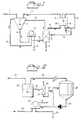
- Figure 1 shows a schematic description of the use of an inorganic ion exchanger in a process for treatment of precipitator dust applying a combination of leaching and electrodialysis treatments.
- Figure 2 shows the application of an inorganic ion exchanger in yet another embodiment in combination with a recrystallisation of sodium sulphate from precipitator dust.
- precipitator dust (1) can be mixed with a near saturated solution of sodium sulphate (2) in a leach tank (3) where the mixed solution can be subjected to a leaching treatment.
- the chloride and potassium compounds in the precipitator dust are leached out and the potassium and chloride enriched solution (31) is brought to an ion exchange column (8).
- a slurry (4) is separated on a filter (5), a centrifuge (not shown) or the similar.
- the filter cake (6) virtually free of chloride and potassium, is recovered to the strong black liquor.
- the filtrate (7) is recycled (71) to the leach tank (3) or forwarded (72) to the ion exchange column (8) where potassium ions are removed (9), and the potassium depleted filtrate, still containing a high concentration of chloride ions (10), can be further brought to the diluate chamber(s) (13) of an electrodialysis stack (11) holding mono-anion selective membranes (12).
- an electric field is applied to the electrodialysis stack the chloride ions are removed by migration through the anion selective membranes to the concentrate (brine) chamber(s) (14).
- the remaining chloride and potassium depleted sodium sulphate solution (2) can be recycled for use as leachant in the first step (3).
- the electrodialysis stack (11) may also comprise cation selective membranes through which cations such as sodium and potassium are removed by migration.
- the concentrated sodium chloride solution prepared in the electrodialysis step (15) can be recirculated back to the concentrate chamber(s) of the cell, but a part may be purged and used for regenerating (16) the ion exchange material.
- water can be added to dilute the concentrated chloride solution (17).
- Precipitator dust (21) can be mixed with water (22) (preferably condensate from the crystallisator (28)) in a dissolving tank (23).
- the dissolved solution (24) is forwarded to an ion exchange column (25), where potassium, are removed (26) and the potassium depleted filtrate (27), may further be brought to a crystallisator (28) where sodium sulphate is re-crystallised from the precipitator dust.
- the solution (29) containing mother liquor and sodium sulphate crystals is brought to a separation step with conventional technique, for instance a vacuum drum filter (30) and an addition of water (31), where the sodium sulphate crystals (32) (Na 2 SO 4 ) is separated from the mother liquor (33).
- Condensed water (22) from the re-crystallisation (28) may be recycled to the dissolving step (23).
- the sodium sulphate crystals can be recycled to the strong black liquor, alternatively can a small portion of the crystals be dissolved in water and used for regeneration of the ion exchanger.
- the mother liquor is preferably discharged.
- the process shown in fig.2 purges a stream of the mother liquor to control the potassium and chloride levels.
- the limiting factor is the solubility of Organic (NaK 3 (SO 4 ) 2 ).
- the concentration of potassium in the precipitator dust solution may vary between 0 and about 35 g/l. After ion exchange, the solution fed to the crystallizator may have a potassium concentration down to 0 g/l.
- a 20 wt% ash solution was prepared from a kraft mill precipitator dust, with a content in the ash of 32 wt% Na, 42 wt% SO 4 , 3.0 wt% K, 3.4 wt% Cl, 16 wt% CO 3 and impurities ⁇ 4 wt%.
- the pH of the solution was adjusted by 50% H 2 SO 4 to pH 7 or 9 and filtered through an OOH filter paper. After that the solution contained about 7.5 g/l potassium.
- the ash solution was mixed with the zeolite and left for stirring for at least 10 minutes. The samples that were run at 50°C the solution was heated and stirred at the same time. When the samples reached 50°C they were stirred for 5 minutes more.
- the zeolites used in the examples were of two different types.
- the Wessalith P is a zeolite manufactured by Degussa. Sodium Mordenite EM120 manufactured by Eka Chemicals in Bohus, Sweden.
- the tested zeolites were powder form. Analyses of potassium content were done on the ash, the start solution and on the filtrate. The experiments were run at pH 7, and at room temperature with different amounts of zeolites. In tables I and II below the results of the removal of potassium in % for each are shown.
- Table I shows the results from the experiments with Wessalith P. Test: 1 2 3 4 5 Amount zeolite [g]/100 ml solution 3,9 5,8 7,8 31 38,8 K in start solution, [g/l] 7,2 7,2 7,2 7,4 7,4 K after treatment, [g/l] 6,5 6,1 5,9 3,9 3,7 Removal of K + [%] 10% 15% 18% 47% 50%
- Table II shows the results from the experiments with Zeolite Sodium Mordenite EM120. test: 1 2 3 4 5 6 Amount zeolite [g]/100 ml solution 3,9 7,8 15,5 23,3 31 38,8 K in start solution, [g/l] 7,7 7,7 7,7 7,2 7,2 7,2 K after treatment, [g/l] 6,2 6,0 4,3 3,3 2,8 2,4 Removal of K + [%] 19% 22% 44% 54% 61% 67%
- a 20 wt% ash solution was prepared from the precipitator dust used in example 1.
- the pH of the solution was adjusted by 50% H 2 SO 4 to pH 8. After that the solution contained about 7.7 g/l potassium.
- the ash solution was mixed with the zeolite and left for stirring for 5 hours at a temperature of 80°C.
- the zeolite used was Sodium Mordenite EM120 manufactured by Eka Chemicals in Bohus, Sweden.
- the zeolite was in powder form. 100ml solution/20g zeolite was used in this test.
- the start concentration of potassium is 7,7g/l.
- Analyses of potassium content and the calculation of amount potassium removed were done in accordance with example 1. Samples were taken once every hour from the solution with the zeolite.
- Amberlite IRC-718 (a cationic exchange resin) manufactured by Rohm and Haas was used in an experiment. Before start the resin was regenerated as follows:
- a 20 wt% ash solution was prepared from the precipitator dust used in example 1.
- the pH of the solution was adjusted by 50% H 2 SO 4 to pH 10.
- the solution contained after that about 7,5 g/l potassium.
- the ash solution was mixed with the wet ion exchanger and stirred for 30min at 40 °C. After that the solution was filtered.
- Analyses of potassium content and the calculation of amount potassium removed were done in accordance with example 1. In table IV below the results of the removal of potassium in % for each are shown.
- the amount of zeolite/100 ml ash solution has been recalculated as dry zeolite.
- Test 1 2 3 Amount zeolite g / 100 ml solution 25 37,5 50 K in start solution [g/l] 7,5 7,5 7,5 K after treatment [g/l] 6,0 5,5 5,1 Removal of K [%] 20 26 32
Landscapes
- Paper (AREA)
- Treatment Of Water By Ion Exchange (AREA)
- Manufacture And Refinement Of Metals (AREA)
Abstract
Description
- The present invention relates to an environmental-friendly process for reducing the content of potassium ions in a liquid inventory of a chemical pulp mill.
- In the production of a chemical pulp, chips of lignocellulose-containing material are cooked in an alkaline or acid aqueous solution. This cooking liquid contains inorganic pulping chemicals to improve the dissolution of lignin. The cooking is normally carried out at a temperature above 100°C to reduce the residence time for the pulp produced. Therefore, the cooking is carried out in a pressure vessel known as a digester.
- In the production of sulphate pulp, soda pulp and sulphite pulp with an alkali metal as a base, normally sodium, it is possible to recover the inorganic pulping chemicals in the spent liquor leaving the digester. It is vital both to economy and environment to recover these pulping chemicals to the largest possible extent. This is achieved in the pulping chemical recovery system, which essentially transfers the used inorganic pulping chemicals into a chemical state, where they can be re-used for cooking.
- An essential part of the recovery system is the recovery boiler, where the spent liquor is burned. Normally, make-up chemicals are added to the spent liquor before the recovery boiler to make up for the chemicals lost during cooking and recovery. The spent liquor is sprayed into the lower part of the boiler, previously at a relatively low temperature to remove free water. Modern recovery boilers operate at a high temperature to reduce the content of sulphur in the flow gases leaving the boiler. Higher up in the boiler, gases and vapours of light hydrocarbons and decomposition products are volatilized. This is known as pyrolysis. Then, the pyrolysis products are burned after mixing with air or oxygen. The solid carbon-based residue which remains after complete pyrolysis of the organics is then heterogeneously burned. The solid particles formed are collected as a dust in precipitators at the top of the recovery boiler, to reduce the release of solid material to the surrounding atmosphere.
- A substantial and increasing problem with the pulping chemical recovery system, is the presence of chloride and potassium in the spent liquor entering the recovery boiler. These elements tend to reduce the capacity of the recovery boiler to produce useful chemicals. Thus, chloride and potassium increase the stickiness of carryover deposits and dust particles to the recovery boiler tubes, which accelerate fouling and plugging in the upper part of the recovery boiler. Chloride also tend to increase the corrosion rate of superheater tubes.
- Chloride and potassium are concentrated in the dust formed during the combustion of spent liquor in the recovery boiler. The dust is collected in dry-bottom or wet-bottom electrostatic precipitators. The dust mainly consists of sodium and potassium salts, where sulphate, carbonate and chloride are the dominant anions. The amount of dust corresponds to from about 5 up to about 15% by weight of the sodium entering the recovery boiler, which corresponds to from about 50 up to about 150 kg dust per tonne pulp, if the dust is calculated as sodium sulphate.
- Today, normally all of the precipitator dust collected and withdrawn from the recovery boiler is recycled to the flow of spent liquor to be burned in the boiler. When the concentration of chloride or potassium is too high, a portion of the precipitator dust is withdrawn from the system and discharged or deposited.
- The largest source of potassium is the wood, and the intake will depend on the wood source generally varying from about 0,5 to 5 kg per tonne pulp. The hardwood species usually contains larger amounts of potassium than softwood species. Besides, the content of chloride in the spent liquor can be very high for coastal mills, if the raw material consists of logs floated in seawater. As the environmental legislation becomes more stringent regarding pulp mill discharges to air and water, the degree of system closure increases. This means that even a small input of chloride and potassium becomes a severe problem, unless the content can be controlled by purging the system in some environmentally acceptable way.
- Several methods have been proposed to overcome the problem with chloride and potassium build-up in pulping chemical recovery systems. The use of organic ion exchangers have been proposed as a unit operation for treatment of precipitator dust, but this has mainly been for softening purposes, e.g. to reduce the content of multivalent metals that would harm membranes in subsequent electrolysis of the precipitator dust. Chloride and potassium removal are preferably carried out in a common waste water treatment. Chloride can be removed efficiently by e.g. electrodialysis, while potassium still is difficult to remove efficiently electrochemically.
- For instance, WO-A1-9404747 discloses a process, in which the content of potassium and chloride in a recovery system for pulping chemicals can be reduced. The process comprises collecting precipitator dust, dissolving the dust in water to produce an aqueous solution of precipitator dust, whereupon said aqueous solution is electrolysed in a cell for production of chlorine or hydrochloric acid in the anolyte. Use of ion exchange is suggested as a pretreatment before the electrolyses, chiefly to remove divalent ions such as Ca2+ and Mg2+. Further, the membrane used in the electrochemical cell can be of an inorganic ion-exchange type.
- Caron J. R. et al, "Metals management in a closed kraft mill bleach plant", Pulping Conference, TAPPI (1995), p. 1155-1160, have investigated metals removal from recycled chlorine dioxide bleach plant filtrate with ion exchange resins.
- The present invention relates to a process according to claim 1 by which the content of potassium ions in a recovery system for pulping chemicals can be reduced.
- An advantage of the present process is the possibility to reduce the content of potassium in the liquid inventory and more particularly in the spent liquor entering the recovery boiler. By the present process, the problem of sticky deposits in the recovery boiler can be substantially reduced. This means an improved energy efficiency as well as a higher degree of recovery of the pulping chemicals.
- The present invention can be used in the production of a chemical pulp and especially for production of a sulphate pulp, soda pulp or sulphite pulp with an alkali metal as base. A kraft pulp is a special type of sulphate pulp, where the pulp is under-cooked to produce a dark-coloured pulp of exceptional strength. The present invention can also be used in the production of sulphate, soda or sulphite pulps with an alkali metal as base, where the cooking processes have been modified, combined or extended compared to the normal pulping techniques. Suitably, the present process is applied where the recovery system for pulping chemicals is a kraft recovery system.
- A liquid inventory is the total quantity of various liquids in a mill, with varying contents of active or activatable cooking liquid components. The liquid inventory of a sulphate mill, mainly consists of white liquor, black liquor, green liquor and spent liquor entering the recovery boiler. The spent liquor to be burned in the present process, is a used cooking liquid withdrawn from a digester, optionally with added make-up chemicals. Potassium and sodium are alkali metals present in the spent liquors.
- The amount of precipitator dust formed depends mainly on the temperature in the boiler, the ratio between sodium and sulphur in the spent liquor and the raw material and sulphidity of the cooking process. A high temperature in the lower part of the boiler to reduce the sulphur content in the flow gases, increases the amount of dust formed.
- With the present process, all or a portion of the precipitator dust collected and withdrawn from the recovery system is treated with an inorganic ion exchange material.
- The composition of precipitator dust formed in recovery boilers vary considerably depending on type and origin of wood, cooking process, purity of make-up chemicals, temperature in the boiler, type of precipitator etc. However, irrespective of these factors the dust mainly consists of sodium and potassium salts, where sulphate, carbonate and chloride are the dominant anions. A typical composition of precipitator dust from a kraft recovery system is Na2SO4 80-85% by weight, Na2CO3 2-8% by weight, NaCI 2-8% by weight, NaHSO4 + Na2S2O7 < 2% by weight, K2SO4 5-10% by weight, K2CO3 0.5-1% by weight, KCI < 1% by weight, metal ions such as Ca, Fe, Mg, P, Si, Mn, Zn, Mo < 1% by weight and organic material < 1 % by weight.
- A suitable zeolite used in the present invention is mordenite, exemplified by Sodium Mordenite EM120 manufactured by Eka Chemicals AB.
- Suitably, the amount of inorganic ion exchange material used is based upon the ion exchange capacity of the actual inorganic material and the amount of potassium in the precipitator dust. The inorganic ion exchange material is preferably used in excess of the stoicheometric amount of potassium.
- The potassium and chloride containing solution is treated with an inorganic ion exchange material. The ion exchanged material, enriched on potassium, is then preferably filtered and washed with water, whereafter the spent ion exchanger material can be deposited in a land fill. The solution depleted on potassium and chloride, can be recycled in the pulp mill or forwarded to another step in the treatment of precipitator dust for mixing or dilution. The separation and washing can preferably take place in a centrifuge, a filter press or a vacuum filter.
- Alternatively, after separating the ion exchanged slurry from the solution, it can be regenerated with a sodium rich aqueous solution. This could for example be a solution of the Na2SO4 salt cake obtained from a chlorine dioxide generator (or from a crystallisator, or a chloride concentrate from an electrochemical cell). Separation, washing, regeneration and dewatering then may take place in the same piece of equipment operating in a continuos mode. Even the ion exchange may take place in the separation equipment. This can be done batchwise in a filter press or continuos eg. in a centrifuge or a rotating filter of vacuum or pressure type.
- In an embodiment of the present invention, the inorganic ion exchange material is made in the form of granules or pellets and are placed as a fixed bed in a column, thus forming an ion exchanger. The precipitator dust solution, rich on potassium, is forced to flow through the bed of ion exchange material to which the potassium is adsorbed. The reaction zone proceeds down the column as the upper layers of ion exchange material reaches equilibrium with the solution. At the end of the work cycle when the ion exchanger becomes exhausted, the ion exchange material is backwashed (regenerated) with a sodium electrolyte. The flow of potassium rich solution is simultaneously switched to another column. A number of columns can be arranged in parallel so that the continuos operation is ensured. The advantage with this embodiment, columns arranged in parallel, over the previously described is that the operation is continuous and that a more efficient ion exchange can be achieved as multiple equilibrium stages are obtained (cf. McKabe-Thiele diagram).
- The amount potassium removed in a precipitator dust solution subjected to a treatment with an inorganic ion exchange material, can be above about 40 %, suitably above about 50 %, preferably above about 60 % and most preferred above about 70 %.
- A potassium free or potassium depleted stream which has undergone the inorganic ion exchange, is preferably recycled to the weak black liquor or may, in the cases where the water balance allows, be mixed with the strong black liquor and fed directly into the recovery boiler in the recovery system.
- A solution of precipitator dust will also commonly have a pH between about 7 and about 11, within which range most ion exchange material are stable and thus preferred. However, the pH is not critical since many ion exchange material work satisfactory outside the pH range 7-11.
- The ion exchange is suitably performed in the range from above 0°C up to about 100°C and preferably from about 20°C up to about 60°C.
- The residence time for the suitable batchwise ion exchange is preferably at least about 1 minute. Suitably the residence time is at least about 1 hour, preferably at least about 2 hours and most preferred at least about 5 hours. The upper residence time is not critical, but have to be set by process-technical reasons. The flow rate for the suitable continuous operation of the ion exchange is suitably at least from about 0.1 up to 20 BV/h (Bed Volume per hour), preferably from about 1 up to 10 BV/h and most preferred from about 2 up to 6 BV/h. The ion exchange is preferably carried out by a continuous operation.
- In one embodiment of the invention the potassium concentration of the solution is increased by leaching the precipitator dust with a liquor. The added liquid may comprise of water, or water solutions of sulphate or carbonate. Added sulphate may be alkali metal, preferably sodium sulphate, suitably at least a part derives from a recirculated solution, depleted of chloride and potassium, for instance from a suitable electrochemical treatment or recrystallisation. If water is added, it can be either fresh water or purified process water. The potassium enriched leach solution is separated from the solid phase of the leached precipitator dust, by e.g. filtration, centrifugation, sedimentation etc..
- The concentrate in the slurry obtained from the leaching step may comprise from about 1 g/l up to about 60 g/l potassium, and will be saturated with sulphate.
- The solution depleted of potassium obtained from the ion exchange may comprise from 0 g/l up to about 60 g/l potassium (counted as e.g. K+, K2SO4, KCI).
- The inorganic ion exchange according to the present invention is preferably combined with another process. This could for example be a process for leaching and electrodialysis of precipitator dust. The ion exchange can also be combined with processes where precipitator dust is split in electrolysis cell or a electrodialysis cell with bipolar membranes. The advantage is, especially when removing the potassium prior to electrolysis, that NaOH with little or no potassium impurities can be prepared.
- The inorganic ion exchange according to the present invention can also be combined with a process where sodium sulphate is re-crystallised from the precipitator dust. In another embodiment, the inorganic ion exchange according to the present invention can be advantageously combined with a process where chloride ions are ion exchanged from the precipitator dust (for instance the Precipitator Dust Purification System, PDP™).
- Another possible application is to use the inorganic ion exchange according to the present invention on bleach filtrates recovered back to the chemical recovery.
- Embodiments of the process of the present invention will now be described in more detail with reference to figures. Figure 1 shows a schematic description of the use of an inorganic ion exchanger in a process for treatment of precipitator dust applying a combination of leaching and electrodialysis treatments. Figure 2 shows the application of an inorganic ion exchanger in yet another embodiment in combination with a recrystallisation of sodium sulphate from precipitator dust.
- In the embodiment of fig. 1, precipitator dust (1) can be mixed with a near saturated solution of sodium sulphate (2) in a leach tank (3) where the mixed solution can be subjected to a leaching treatment. The chloride and potassium compounds in the precipitator dust are leached out and the potassium and chloride enriched solution (31) is brought to an ion exchange column (8). A slurry (4) is separated on a filter (5), a centrifuge (not shown) or the similar. The filter cake (6), virtually free of chloride and potassium, is recovered to the strong black liquor. The filtrate (7) is recycled (71) to the leach tank (3) or forwarded (72) to the ion exchange column (8) where potassium ions are removed (9), and the potassium depleted filtrate, still containing a high concentration of chloride ions (10), can be further brought to the diluate chamber(s) (13) of an electrodialysis stack (11) holding mono-anion selective membranes (12). When an electric field is applied to the electrodialysis stack the chloride ions are removed by migration through the anion selective membranes to the concentrate (brine) chamber(s) (14). The remaining chloride and potassium depleted sodium sulphate solution (2) can be recycled for use as leachant in the first step (3). The electrodialysis stack (11) may also comprise cation selective membranes through which cations such as sodium and potassium are removed by migration. The concentrated sodium chloride solution prepared in the electrodialysis step (15) can be recirculated back to the concentrate chamber(s) of the cell, but a part may be purged and used for regenerating (16) the ion exchange material. In addition, water can be added to dilute the concentrated chloride solution (17).
- The advantage with implementing potassium ion exchange in the process described in fig. 1 is obvious. Chloride and sulphate ions can efficiently be separated in the electrodialyser as the divalent sulphate ions will be repelled by the mono-anion selective membranes. Unfortunately, cation exchange membranes cannot exhibit a similar selectivity for potassium versus sodium. Consequently, only a minor part of the potassium will be removed in the electrodialysis step and without any selective potassium removal the concentration of potassium will increase in the solution until the solubility limit for glacerite (NaK3(SO4)2) is reached. As a consequence, the main part of the potassium will follow the cake resulting in a low removal efficiency for potassium. With the ion exchange the potassium concentration can be kept below solubility and potassium removal efficiency is improved.
- In fig.2, an embodiment is shown where an ion exchanger is combined with a process where sodium sulphate is re-crystallised from the precipitator dust. Precipitator dust (21) can be mixed with water (22) (preferably condensate from the crystallisator (28)) in a dissolving tank (23). The dissolved solution (24) is forwarded to an ion exchange column (25), where potassium, are removed (26) and the potassium depleted filtrate (27), may further be brought to a crystallisator (28) where sodium sulphate is re-crystallised from the precipitator dust. The solution (29) containing mother liquor and sodium sulphate crystals is brought to a separation step with conventional technique, for instance a vacuum drum filter (30) and an addition of water (31), where the sodium sulphate crystals (32) (Na2SO4) is separated from the mother liquor (33). Condensed water (22) from the re-crystallisation (28) may be recycled to the dissolving step (23). The sodium sulphate crystals can be recycled to the strong black liquor, alternatively can a small portion of the crystals be dissolved in water and used for regeneration of the ion exchanger. The mother liquor is preferably discharged.
- The process shown in fig.2, purges a stream of the mother liquor to control the potassium and chloride levels. As described in connection to fig 1. above, the limiting factor is the solubility of glacerite (NaK3(SO4)2). When the potassium level is kept down, either by ion exchanging the feed solution or a small side stream of mother liquor, the chloride levels in the mother liquor can be increased and the purge flow can be reduced. In other words less sodium and sulphate are lost with the purge. The concentration of potassium in the precipitator dust solution may vary between 0 and about 35 g/l. After ion exchange, the solution fed to the crystallizator may have a potassium concentration down to 0 g/l.
- The invention and its advantages are illustrated in more detail by the following examples which, however, are only intended to illustrate the invention and not to limit the same. The percentages and parts used in the description, claims and examples, refer to percentages by weight and parts by weight, unless otherwise specified.
- A 20 wt% ash solution was prepared from a kraft mill precipitator dust, with a content in the ash of 32 wt% Na, 42 wt% SO4, 3.0 wt% K, 3.4 wt% Cl, 16 wt% CO3 and impurities < 4 wt%. The pH of the solution was adjusted by 50% H2SO4 to pH 7 or 9 and filtered through an OOH filter paper. After that the solution contained about 7.5 g/l potassium. The ash solution was mixed with the zeolite and left for stirring for at least 10 minutes. The samples that were run at 50°C the solution was heated and stirred at the same time. When the samples reached 50°C they were stirred for 5 minutes more. For filtration of the solution, a Millipore equipment and a nylon filter paper with a pore size of 0.45 µm were used. The zeolites used in the examples were of two different types. The Wessalith P is a zeolite manufactured by Degussa. Sodium Mordenite EM120 manufactured by Eka Chemicals in Bohus, Sweden. The tested zeolites were powder form. Analyses of potassium content were done on the ash, the start solution and on the filtrate. The experiments were run at pH 7, and at room temperature with different amounts of zeolites. In tables I and II below the results of the removal of potassium in % for each are shown. The amount of zeolite/100 ml ash solution has been recalculated as dry zeolite. The removal of potassium is calculated on the concentration in the start solution and the filtrate as follows:
- Table I shows the results from the experiments with Wessalith P.
Test: 1 2 3 4 5 Amount zeolite [g]/100 ml solution 3,9 5,8 7,8 31 38,8 K in start solution, [g/l] 7,2 7,2 7,2 7,4 7,4 K after treatment, [g/l] 6,5 6,1 5,9 3,9 3,7 Removal of K+ [%] 10% 15% 18% 47% 50% - As evident from table I, the removal of potassium with Wessalith P was efficient and increases with increasing addition of the zeolite.
- Table II shows the results from the experiments with Zeolite Sodium Mordenite EM120.
test: 1 2 3 4 5 6 Amount zeolite [g]/100 ml solution 3,9 7,8 15,5 23,3 31 38,8 K in start solution, [g/l] 7,7 7,7 7,7 7,2 7,2 7,2 K after treatment, [g/l] 6,2 6,0 4,3 3,3 2,8 2,4 Removal of K+ [%] 19% 22% 44% 54% 61% 67% - As shown in table II, the removal of potassium with Zeolite Sodium Mordenite EM120 was further improved, resulting in about 15 % higher removal rate than with the Wessalith P zeolite.
- A 20 wt% ash solution was prepared from the precipitator dust used in example 1. The pH of the solution was adjusted by 50% H2SO4 to pH 8. After that the solution contained about 7.7 g/l potassium. The ash solution was mixed with the zeolite and left for stirring for 5 hours at a temperature of 80°C. The zeolite used was Sodium Mordenite EM120 manufactured by Eka Chemicals in Bohus, Sweden. The zeolite was in powder form. 100ml solution/20g zeolite was used in this test. The start concentration of potassium is 7,7g/l. Analyses of potassium content and the calculation of amount potassium removed were done in accordance with example 1. Samples were taken once every hour from the solution with the zeolite. The stirrer was turned off and sample was taken from the clear phase. In table III below the results of the removal of potassium in % for each hour is shown.
Time [h]: 1 2 3 4 5 Removal of K+ [%]: 32.5 33.8 35.1 36.4 40.3 - As evident from table III, the removal of potassium with Zeolite Sodium Mordenite EM120 increased with time.
- For comparative reasons, Amberlite IRC-718 (a cationic exchange resin) manufactured by Rohm and Haas was used in an experiment. Before start the resin was regenerated as follows:
- 1. 300ml Amberlite was added to 1200ml 4% HCI and stirred for 30min.
- 2. Wash with water (Filter paper and funnel).
- 3. The Amberlite was added to 3000ml 4% NaOH and stirred for 30min.
- 4. Wash with water (water and Amberlite were mixed and stirred for some minutes and
wash of the Amberlite as in 2, this was repeated several times).
pH 10,9 after 3,5 hour. -
- A 20 wt% ash solution was prepared from the precipitator dust used in example 1. The pH of the solution was adjusted by 50% H2SO4 to
pH 10. The solution contained after that about 7,5 g/l potassium. The ash solution was mixed with the wet ion exchanger and stirred for 30min at 40 °C. After that the solution was filtered. Analyses of potassium content and the calculation of amount potassium removed were done in accordance with example 1. In table IV below the results of the removal of potassium in % for each are shown. The amount of zeolite/100 ml ash solution has been recalculated as dry zeolite.Test 1 2 3 Amount zeolite g / 100 ml solution 25 37,5 50 K in start solution [g/l] 7,5 7,5 7,5 K after treatment [g/l] 6,0 5,5 5,1 Removal of K [%] 20 26 32 - As evident from table IV, the removal of potassium with Amberlite IRC-718 is poor, compared to the inorganic ion exchange material used in examples 1 and 2.
- In this experiment a continuous ion exchange was carried out. The equipment used were a glass column, a conduit for continuously separating a bleed from the top of the column to a balance, a balance with the feed solution in connection to a pump for continuously feeding the solution from the bottom of the column and a pump control unit. In each trial the column was packed with fresh zeolite granules. Potassium were analysed by AAS (Atomic Absorption Spectra). In trials no 1-3 a real precipitator dust solution were used. A 5 wt % solution was prepared from Weyerhaeuser precipitator dust (see example 1). The pH was adjusted by 50 % H2SO4 to pH of 7 and the solution was filtered through a 00H filter paper. A new solution was prepared in each trial. Table V shows the precipitator dust solution content.
K g/l Na g/l Cl g/l SO4 g/ l pH 1,5 ∼16 ∼1,7 ∼21 7 - The used regeneration solutions has been 3 M NaAc and 3M NH4 Cl. The variables can be seen in table VI. Rex = regeneration. IEx = ion exchange. BV=Bed Volume. Trial no.1 is Wessalith MS 330, no.2 is Ammonium Mordenite and no.3 is Sodium mordenite.
Trial No. Amount Zeolite [g] Flow [BV/ h] IE time [min] Temp [° C] Performed series Regeneration (Re), Solution, time 1 30.1 18 100 25 Re0 IE1 Re1 IE2 NH4Cl 90 minutes 2 27 18 100 25 Re0 IE1 Re1 IE2 NaAc 90 minutes 3 31 18 100 25 Re0 IE1 Re1 IE2 NH4Cl 90 minutes - In table VII below, the continuous ion exchange on precipitator dust solution is shown.
Zeolite type / trial No IE-stage Rem % K 20 minutes Rem % K 50 minutes Rem % K 70 minutes Rem % K 100 minutes Wessalith MS 330 / trial no.1 IE1 41,1 26,9 22,5 18,2 IE2 39,9 26,7 21,9 17,7 Ammonium Mordenite EM 032 / trial no. 2 IE 150,4 35,8 30,9 25,7 IE2 45,1 33,2 28,4 23,0 Sodium mordenite EM 120 / trial no.3 IE 165,2 52,8 44,5 36,2 IE 276,5 44,3 37,2 29,6 - As evident from table VII above, it is possible to achieve a high removal of potassium from a precipitator dust solution when using a continuous operation. The results from these trials also show that the zeolites can be regenerated and used again.
Claims (7)
- A process for reducing the content of potassium ions in a recovery system for pulping chemicals by bringing spent liquor to a recovery boiler, burning said spent liquor, collecting precipitator dust formed, forming a solution by dissolving the precipitator dust in a liquid, characterisedin that the solution of precipitator dust is subjected to a treatment with an inorganic ion exchange material which is mordenite (8;25) in order to remove at least a part of the potassium therein.
- A process according to any of the preceding claims, characterised in that the treatment is carried out batchwise, with a residence time of at least about 2 hours.
- A process according to any of claim 1-4, characterised in that the treatment is carried out in a continuous operation, with a flow rate from about 1 up to 10 BV/h.
- A process according to claim 1, characterised in that the inorganic ion exchange material is used in a process for leaching (3) and electrodialysis (11).
- A process according to claim 1, characterised in that the inorganic ion exchange material is used in a process for re-crystallisation (28) of sodium sulphate from a chloride and potassium enriched mother liquor.
- A process according to claim 1, characterised in that the inorganic ion exchange material is regenerated with an internal chloride concentrated solution (16) received in the process for removal of potassium from precipitator dust.
- A process according to claim 1, characterised in that the amount potassium removed from said precipitator dust solution, subjected to the treatment with said inorganic ion exchange material, is above about 50 %.
Applications Claiming Priority (2)
| Application Number | Priority Date | Filing Date | Title |
|---|---|---|---|
| SE9700012A SE9700012D0 (en) | 1997-01-03 | 1997-01-03 | Recovery process in a pulp mill |
| SE9700012 | 1997-01-03 |
Publications (2)
| Publication Number | Publication Date |
|---|---|
| EP0852272A1 EP0852272A1 (en) | 1998-07-08 |
| EP0852272B1 true EP0852272B1 (en) | 2002-03-27 |
Family
ID=20405353
Family Applications (1)
| Application Number | Title | Priority Date | Filing Date |
|---|---|---|---|
| EP97203861A Expired - Lifetime EP0852272B1 (en) | 1997-01-03 | 1997-12-10 | Recovery process in a pulp mill |
Country Status (7)
| Country | Link |
|---|---|
| EP (1) | EP0852272B1 (en) |
| AT (1) | ATE215143T1 (en) |
| CA (1) | CA2225927C (en) |
| DE (1) | DE69711355T2 (en) |
| ES (1) | ES2171832T3 (en) |
| PT (1) | PT852272E (en) |
| SE (1) | SE9700012D0 (en) |
Families Citing this family (3)
| Publication number | Priority date | Publication date | Assignee | Title |
|---|---|---|---|---|
| WO2015010179A1 (en) * | 2013-07-25 | 2015-01-29 | Noram Engineering And Constructors Ltd. | Method of reducing chloride and potassium ion concentrations in a pulp mill chemical recovery system |
| SE1451569A1 (en) * | 2014-12-17 | 2015-12-01 | Aprotech Engineering Ab | Process for production of a fertilizer comprising potassiumsulfate |
| FI129103B (en) | 2017-04-28 | 2021-07-15 | Andritz Oy | Method for processing fly ash of a recovery boiler |
Family Cites Families (4)
| Publication number | Priority date | Publication date | Assignee | Title |
|---|---|---|---|---|
| US3684672A (en) * | 1969-08-07 | 1972-08-15 | Mitsubishi Heavy Ind Ltd | Process for paper manufacture |
| US5352332A (en) * | 1991-01-28 | 1994-10-04 | Maples Gerald E | Process for recycling bleach plant filtrate |
| SE9202419D0 (en) * | 1992-08-24 | 1992-08-24 | Eka Nobel Ab | REDUCTION OF CHLORIDE IN PULPING CHEMICAL RECOVERY SYSTEMS |
| SE9502583D0 (en) * | 1995-07-12 | 1995-07-12 | Eka Chemicals Ab | Leaching process |
-
1997
- 1997-01-03 SE SE9700012A patent/SE9700012D0/en unknown
- 1997-12-10 DE DE69711355T patent/DE69711355T2/en not_active Expired - Lifetime
- 1997-12-10 PT PT97203861T patent/PT852272E/en unknown
- 1997-12-10 AT AT97203861T patent/ATE215143T1/en active
- 1997-12-10 EP EP97203861A patent/EP0852272B1/en not_active Expired - Lifetime
- 1997-12-10 ES ES97203861T patent/ES2171832T3/en not_active Expired - Lifetime
- 1997-12-29 CA CA002225927A patent/CA2225927C/en not_active Expired - Fee Related
Also Published As
| Publication number | Publication date |
|---|---|
| CA2225927C (en) | 2002-04-09 |
| ES2171832T3 (en) | 2002-09-16 |
| CA2225927A1 (en) | 1998-07-03 |
| PT852272E (en) | 2002-08-30 |
| DE69711355T2 (en) | 2002-10-31 |
| ATE215143T1 (en) | 2002-04-15 |
| EP0852272A1 (en) | 1998-07-08 |
| SE9700012D0 (en) | 1997-01-03 |
| DE69711355D1 (en) | 2002-05-02 |
Similar Documents
| Publication | Publication Date | Title |
|---|---|---|
| US8246779B2 (en) | Maintenance of sulfur concentration in Kraft pulp processes | |
| AU688683B2 (en) | Leaching process | |
| WO1998016462A1 (en) | Treatment of chlorine dioxide generator effluent and feed streams with fixed-resin bed | |
| EP0088456B1 (en) | Process for the continuous removal of silicic acid from waste liquors deriving from cellulose pulp production | |
| US5961803A (en) | Leaching process | |
| US2736635A (en) | Method of producing sulfite cooking liquors and recovering valuable constituents therefrom | |
| US5922171A (en) | Method and apparatus for removing sodium chloride from pulping chemicals using an amphoteric ion-exchange resin | |
| US5980717A (en) | Recovery process in a pulp mill | |
| US5628874A (en) | Reduction of chloride in pulping chemical recovery systems | |
| EP0852272A1 (en) | Recovery process in a pulp mill | |
| EP1566480B1 (en) | Process for producing kraft pulp | |
| US3950217A (en) | Removal of sodium chloride from pulping operations | |
| DE3613959C2 (en) | ||
| EP0954632B1 (en) | A process for the separation of a sulphur-containing component from pulping liquors using amphoteric resins | |
| CA2256923A1 (en) | Kraft pulping process | |
| CA3019505A1 (en) | Selective removal of k+ and cl- from recovery boiler electrostatic precipitator ashes in a kraft process | |
| CA1059271A (en) | Removal of sodium chloride from pulp mill systems | |
| EP4428299A1 (en) | System and method for the removal of non-process elements from electrostatic precipitator ashes in a kraft pulp process | |
| US2785955A (en) | Method for recovering base ions from waste sulfite liquor and producing sulfite cooking liquor | |
| CA2259109C (en) | Kraft pulping process | |
| SU1109057A3 (en) | Method of obtaining cellulose | |
| US3175880A (en) | Chemical recovery by ion exclusion from neutral sulfite semichemical spent liquor | |
| DD242604A1 (en) | METHOD FOR RECOVERY OF MAGNESIUM FROM COOLING VENTURIATION PROCESSING IN MAGNESIUM BISULFITE CIRCUIT |
Legal Events
| Date | Code | Title | Description |
|---|---|---|---|
| PUAI | Public reference made under article 153(3) epc to a published international application that has entered the european phase |
Free format text: ORIGINAL CODE: 0009012 |
|
| AK | Designated contracting states |
Kind code of ref document: A1 Designated state(s): AT DE ES FI FR PT SE |
|
| AX | Request for extension of the european patent |
Free format text: AL;LT;LV;MK;RO;SI |
|
| 17P | Request for examination filed |
Effective date: 19980527 |
|
| AKX | Designation fees paid |
Free format text: AT DE ES FI FR PT SE |
|
| AXX | Extension fees paid |
Free format text: SI PAYMENT 980527 |
|
| RBV | Designated contracting states (corrected) |
Designated state(s): AT DE ES FI FR PT SE |
|
| GRAG | Despatch of communication of intention to grant |
Free format text: ORIGINAL CODE: EPIDOS AGRA |
|
| 17Q | First examination report despatched |
Effective date: 20010316 |
|
| GRAG | Despatch of communication of intention to grant |
Free format text: ORIGINAL CODE: EPIDOS AGRA |
|
| GRAH | Despatch of communication of intention to grant a patent |
Free format text: ORIGINAL CODE: EPIDOS IGRA |
|
| GRAH | Despatch of communication of intention to grant a patent |
Free format text: ORIGINAL CODE: EPIDOS IGRA |
|
| GRAA | (expected) grant |
Free format text: ORIGINAL CODE: 0009210 |
|
| AK | Designated contracting states |
Kind code of ref document: B1 Designated state(s): AT DE ES FI FR PT SE |
|
| AX | Request for extension of the european patent |
Free format text: SI PAYMENT 19980527 |
|
| REF | Corresponds to: |
Ref document number: 215143 Country of ref document: AT Date of ref document: 20020415 Kind code of ref document: T |
|
| REF | Corresponds to: |
Ref document number: 69711355 Country of ref document: DE Date of ref document: 20020502 |
|
| ET | Fr: translation filed | ||
| REG | Reference to a national code |
Ref country code: PT Ref legal event code: SC4A Free format text: AVAILABILITY OF NATIONAL TRANSLATION Effective date: 20020528 |
|
| REG | Reference to a national code |
Ref country code: ES Ref legal event code: FG2A Ref document number: 2171832 Country of ref document: ES Kind code of ref document: T3 |
|
| PLBE | No opposition filed within time limit |
Free format text: ORIGINAL CODE: 0009261 |
|
| STAA | Information on the status of an ep patent application or granted ep patent |
Free format text: STATUS: NO OPPOSITION FILED WITHIN TIME LIMIT |
|
| 26N | No opposition filed |
Effective date: 20021230 |
|
| PGFP | Annual fee paid to national office [announced via postgrant information from national office to epo] |
Ref country code: SE Payment date: 20131230 Year of fee payment: 17 Ref country code: PT Payment date: 20130611 Year of fee payment: 17 Ref country code: AT Payment date: 20131120 Year of fee payment: 17 Ref country code: DE Payment date: 20131230 Year of fee payment: 17 |
|
| PGFP | Annual fee paid to national office [announced via postgrant information from national office to epo] |
Ref country code: ES Payment date: 20131226 Year of fee payment: 17 Ref country code: FR Payment date: 20131217 Year of fee payment: 17 Ref country code: FI Payment date: 20131230 Year of fee payment: 17 |
|
| REG | Reference to a national code |
Ref country code: PT Ref legal event code: MM4A Free format text: LAPSE DUE TO NON-PAYMENT OF FEES Effective date: 20150611 |
|
| REG | Reference to a national code |
Ref country code: DE Ref legal event code: R119 Ref document number: 69711355 Country of ref document: DE |
|
| PG25 | Lapsed in a contracting state [announced via postgrant information from national office to epo] |
Ref country code: PT Free format text: LAPSE BECAUSE OF NON-PAYMENT OF DUE FEES Effective date: 20150611 Ref country code: SE Free format text: LAPSE BECAUSE OF NON-PAYMENT OF DUE FEES Effective date: 20141211 Ref country code: FI Free format text: LAPSE BECAUSE OF NON-PAYMENT OF DUE FEES Effective date: 20141210 |
|
| REG | Reference to a national code |
Ref country code: SE Ref legal event code: EUG |
|
| REG | Reference to a national code |
Ref country code: AT Ref legal event code: MM01 Ref document number: 215143 Country of ref document: AT Kind code of ref document: T Effective date: 20141210 |
|
| REG | Reference to a national code |
Ref country code: FR Ref legal event code: ST Effective date: 20150831 |
|
| PG25 | Lapsed in a contracting state [announced via postgrant information from national office to epo] |
Ref country code: DE Free format text: LAPSE BECAUSE OF NON-PAYMENT OF DUE FEES Effective date: 20150701 |
|
| PG25 | Lapsed in a contracting state [announced via postgrant information from national office to epo] |
Ref country code: FR Free format text: LAPSE BECAUSE OF NON-PAYMENT OF DUE FEES Effective date: 20141231 Ref country code: AT Free format text: LAPSE BECAUSE OF NON-PAYMENT OF DUE FEES Effective date: 20141210 |
|
| REG | Reference to a national code |
Ref country code: ES Ref legal event code: FD2A Effective date: 20160129 |
|
| PG25 | Lapsed in a contracting state [announced via postgrant information from national office to epo] |
Ref country code: ES Free format text: LAPSE BECAUSE OF NON-PAYMENT OF DUE FEES Effective date: 20141211 |