EP0851242A2 - Radiation detector using scintillation fibers - Google Patents
Radiation detector using scintillation fibers Download PDFInfo
- Publication number
- EP0851242A2 EP0851242A2 EP97111645A EP97111645A EP0851242A2 EP 0851242 A2 EP0851242 A2 EP 0851242A2 EP 97111645 A EP97111645 A EP 97111645A EP 97111645 A EP97111645 A EP 97111645A EP 0851242 A2 EP0851242 A2 EP 0851242A2
- Authority
- EP
- European Patent Office
- Prior art keywords
- scintillation
- fiber
- scintillation fiber
- radiation detector
- fibers
- Prior art date
- Legal status (The legal status is an assumption and is not a legal conclusion. Google has not performed a legal analysis and makes no representation as to the accuracy of the status listed.)
- Granted
Links
Images


Classifications
-
- G—PHYSICS
- G01—MEASURING; TESTING
- G01T—MEASUREMENT OF NUCLEAR OR X-RADIATION
- G01T1/00—Measuring X-radiation, gamma radiation, corpuscular radiation, or cosmic radiation
- G01T1/16—Measuring radiation intensity
- G01T1/20—Measuring radiation intensity with scintillation detectors
- G01T1/201—Measuring radiation intensity with scintillation detectors using scintillating fibres
Definitions
- the present invention relates to a radiation detector which uses a scintillation fiber to detect a incident position, a radiation dose or a radiation dose-rate of a radiation in a monitoring required environment such as a radiation controlled area.
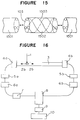
- FIG 16 there is shown a block diagram of the structure of a conventional scintillation fiber used radiation detector which has been described in e.g. "radiation detectors and their application” (published by High Energy Physics Research Institute on January 26 and 27, 1994).
- reference numeral 1 designates a collimated radiation.
- Reference numerals 2a and 2b designate light pulses produced by fluorescent.
- Reference numeral 3 designates a scintillation fiber.
- Reference numerals 4a and 4b designate two light-receiving elements which are connected to opposite ends of the scintillation fiber 3.
- Reference numerals 5a and 5b designate two pre-amplifiers.
- Reference numerals 6a and 6b designate two constant-fraction discriminators.
- Reference numeral 7 designates a signal delay circuit.
- Reference numeral 8 designates a time-to-amplitude convertor.
- Reference numeral 9 designates an analog-digital convertor.
- Reference numeral 10 designates a multichannel pulse-height analyzer
- the two light pulses 2a and 2b are inputted in the light-receiving elements 4a and 4b, are converted into electrical pulse signals there, are inputted into the time-to-amplitude convertor 8 through the constant-fraction discriminators 6a and 6b, and the signal delay circuit 7.
- An electrical pulse is outputted from the time-to-amplitude converter 8 so as to have a pulse-height in proportion to the time difference between the time periods required for the light pulses to reach the respective light-receiving elements 4a and 4b.
- the pulse from the time-to-amplitude convertor is inputted into the analog-digital convertor 9.
- the scintillation fiber 3 Although more than one radiation 1 can be incident on the scintillation fiber 3, it is possible to see the incident positions of the radiations 1 by discriminating the pulse-heights of the electrical pulses at the multichannel pulse-height analyzer 10, and to detect a radiation dose-rate based on count.
- the conventional scintillation fiber 3 is constituted by a single member except that it is covered by a shade tube.
- the conventional scintillation fiber used radiation detector has the scintillation fiber 3 constituted by a single member as stated earlier, the radiation detector has created a problem in that the probability of interaction is low and detection sensitivity is low since a radiation having a penetrative capacity penetrates the scintillation fiber.
- the scintillation fiber itself has great transmission loss, the scintillation fiber is not good at sensitivity and energy characteristics, causing a measurable range of the radiation dose-rate and long-distance transmission to be limited.
- a scintillation fiber used radiation detector has a scintillation fiber arranged in or on a scattering member for emitting an electron by interaction with a radiation.
- the radiation detector has a plurality of scintillation fibers arranged in or on the scattering member.
- the radiation detector has a groove formed in the scattering member to arrange at least one scintillation fiber therein.
- the radiation detector has at least one scintillation fiber connected to at least one optical fiber for transmission having lower transmission loss than the scintillation fiber.
- the radiation detector has connecting ends of the scintillation fiber and the optical fiber for transmission covered by inner connection pipes so that the inner connection pipes have connecting end surfaces arranged to be flush with connecting end surfaces of the scintillation fiber and the optical fiber, the inner connection pipes having respective inner diameters identical to respective outer diameters of the scintillation fiber and the optical fiber.
- the scintillation fiber and the optical fiber are connected by inserting the inner connection pipes in a single outer connection pipe having respective inner diameters identical to respective outer diameter of the respective inner connection pipes.
- the radiation detector has connecting ends of the scintillation fiber and the optical fiber for transmission covered by inner connection pipes so that the inner connection pipes have connecting end surfaces arranged to be flush with connecting end surfaces of the scintillation fiber and the optical fiber, the inner connection pipes having respective inner diameters identical to respective outer diameters of the scintillation fiber and the optical fiber.
- the scintillation fiber and the optical fiber are connected by inserting the inner connection pipes in a single outer connection pipe having respective inner diameter identical to respective outer diameters of the respective inner connection pipes, and interposing an optical element having a light-gathering function between the scintillation fiber and the optical fiber.
- the radiation detector has a plurality of scintillation fibers and a plurality of optical fibers for transmission connected to provide a plurality of composite fibers.
- the composite fibers are arranged to have a portion with the scintillation fiber included therein relatively shifted in a longitudinal direction thereof.
- the radiation detector has the scintillation fiber and the optical fiber for transmission connected to provide a composite fiber.
- the composite fiber has only a portion with the scintillation fiber included therein as a radiation detecting portion provided with the scattering member. A light signal from the radiation detection portion is transmitted to the optical fiber.
- the radiation detector has the scattering member made of a noncombustible material and the scintillation fiber made of a quartz material.
- the radiation detector has the scintillation fiber spirally arranged in or on the scattering member.
- the radiation detector has the scattering member with the scintillation fiber arranged therein or thereon is wound with a heat isolating tape.
- the radiation detector has a plurality of scattering members made of different materials and a plurality of scintillation fibers surrounded by the different scattering members.
- the scintillation fiber can be arranged in or on the scattering member for emitting an electron by interaction with the radiation to improve sensitivity, improve energy characteristics, expand the range of a radiation dose-rate and establish long-distance transmission.
- a wide range of environmental monitoring can be carried out with higher accuracy by a single system to reduce cost.
- a plurality of scintillation fibers can be arranged in or on the scattering member to further raise the probability of reaction with a radiation, increasing the amount of light of a produced light pulse. This can further improve sensitivity, improve energy characteristics, expand the range of a radiation dose-rate and establish long-distance transmission.
- the scattering member which emits an electron by interaction with the radiation has the groove formed therein, and the scintillation fiber is arranged in the groove.
- the scintillation fiber can be protected against an external pressure, be prevented from being damaged or broken on and after installation, and have increased mechanical strength.
- the scintillation fiber can be connected to the optical fiber for transmission having lower transmission loss than the scintillation fiber to establish long-distance transmission of the light produced in the scintillation fiber. This enables further long-distance transmission of a light signal to carry out monitoring in a wider range.
- a detecting unit and a measuring unit can be remotely installed to realize telemetering.
- the scintillation fiber and the optical fiber for transmission when the scintillation fiber and the optical fiber for transmission are connected together, the scintillation fiber and the optical fiber for transmission have the connecting ends covered by inner connection pipes so that the inner connection pipes have the connecting end surfaces arranged to be flush with the connecting end surfaces of the scintillation fiber and the optical fiber, the inner connection pipes have the respective inner diameters identical to the respective outer diameters of the scintillation fiber and the optical fiber.
- the scintillation fiber and the optical fiber are connected by inserting the inner connection pipes in the single outer connection pipe having the respective inner diameters identical to the respective outer diameters of the respective inner connection pipes. This arrangement can make the connected portion firm and small.
- the presence of the connecting portion does not interfere with arrangement of the scintillation fiber in or on the scattering member.
- the connecting portion can have increased mechanical strength.
- the scintillation fiber and the optical fiber for transmission when the scintillation fiber and the optical fiber for transmission are connected together, the scintillation fiber and the optical fiber have the connecting ends covered by the inner connection pipes so that the inner connection pipes have the connecting end surfaces arranged to be flush with the connecting end surfaces of the scintillation fiber and the optical fiber, the inner connection pipes having respective inner diameters identical to the respective outer diameters of the scintillation fiber and the optical fiber.
- the scintillation fiber and the optical fiber are connected by inserting the inner connection pipes in the single outer connection pipe having the respective inner diameters identical to the respective outer diameters of the respective inner connection pipes, and interposing the optical element having a light-gathering function between the scintillation fiber and the optical fiber.
- the plurality of scintillation fibers and the plurality of optical fibers for transmission are connected to provide the plurality of composite fibers, and the composite fibers are arranged to have a portion with the scintillation fiber included therein relatively shifted in a longitudinal direction thereof.
- This arrangement can arrange the radiation detecting portion in a wide range to carry out radiation monitoring in a wider range.
- the scintillation fiber in the scattering member is connected to the optical fiber for transmission having lower transmission loss than the scintillation fiber, the scattering member is arranged only on the radiation detecting portion with the scintillation fiber included therein, and the light signal from the radiation detecting portion is transmitted through the optical fiber without the scattering member arranged thereon, allowing the cost incurred by use of the scattering member to be reduced and production process to be simplified.
- the scattering member which emits an electron by interaction with the radiation is made of a noncombustible material, and the scintillation fiber is made of a quartz material.
- the radiation detector can have a high-temperature-resistant property and a fire-resistant property.
- the scintillation fiber can spirally arranged in or on the scattering member to equalize the sensitivity of the detecting portion irrespectively of the incident direction of the radiation. Even if bending stress is applied to the detecting portion including the scattering member, stress concentration is prevented from causing at a location where the scintillation fiber or the optical fiber for transmission is arranged. In addition, an increase in mechanical strength can be realized.
- the scintillation fiber is arranged in or on the scattering member, and the scattering member is wound with the heat insulating tape, allowing the scintillation fiber to be restrained from deformation and deterioration due to heat.
- the respective scattering members which are arranged on the scintillation fibers are made of different materials. This arrangement can give different energy characteristics to the respective scintillation fibers which are arranged at different positions. It is possible to widen the measurable range for radioactive energy to be measured.
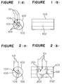
- Figures 1(a) and (b) there are shown schematic views showing the essential parts of the radiation detector according to the first embodiment of the present invention, wherein Figure 1(a) is a cross-sectional view of a scintillation fiber, and Figure 1(b) is a longitudinal cross-sectional view of the scintillation fiber.
- reference numeral 101 designates radiations to be measured.
- Reference numeral 102 designates the scintillation fiber.
- Reference numeral 103 designates a scattering member which emits an electron by interaction with a radiation 101, and which surrounds the scintillation fiber.
- Reference numeral 104 designates interaction points where the radiations 101 interact with the scattering member 103.
- Reference numeral 105 designates electrons, or electrons and radiations which have occurred at the interaction points 104.
- Reference numeral 106 designates fluorescent points which are produced by incidence of the electrons, or the electrons and the radiations 105.
- the radiations 101 When the radiations 101 are incident on the radiation detector thus constructed, some of the radiations directly interact the scintillation fiber 102 to emit electrons so as to produce fluorescent light at the fluorescent points 106. Some of the radiations interact with the scattering member 103 at the interact points 104 to emit electrons, or electrons and radiations 105, and then the electrons, or the electrons and the radiations 105 interact with the scintillation fiber 102 to produce fluorescent light.
- the radiations 101 need to interact directly with the scintillation fiber 102 to produce the fluorescent light. In that case, some of the radiations 101 penetrate the scintillation fiber 102 without interaction therewith. Even if some of the radiations interact with the scintillation fiber to emit electrons, some of the electrons go out of the scintillation fiber 102 without giving the entire energy to the scintillation fiber 102.
- the sensitivity of the radiation detector is determined by whether the fluorescent light can be counted in the scintillation fiber 102 or not. It is determined by with what probability the radiations 101 interact with the scintillation fiber 102, and whether the amount of light emission of the fluorescent can be detected by a measuring unit or not. This means that it is possible to improve the sensitivity of the radiation detector by raising the probability of the interaction between the radiations 101 and the scintillation fiber 102, or by increasing the energy imparting amount to the scintillation fiber 102 due to the interaction.
- the scintillation fiber 102 is surrounded by the scattering member 103 which emits electrons by interaction with the radiations, and which is made of e.g. polyethylene.
- This arrangement can cause the electrons and the radiations 105 emitted from the interaction points 104 to interact with the scintillation fiber 102 and produce fluorescent so as to raise the probability of the interaction between the radiations 101 and the scintillation fiber 102 even if some of the radiations 101 do not directly interact with the scintillation fiber 102.
- this arrangement can provide the scattering member 103 with greater energy than that generated in the scintillation fiber 102, depending on the atomic number of the scattering member 103 and the energy of the radiations 101.
- the energy provided in the scattering member 103 can be sufficiently transmitted to the scintillation fiber 102, the provision of the energy at the fluorescent points 106, i.e. the amount of light emission of the fluorescent can be increased in comparison with the absence of the scattering member 103 around the scintillation fiber 102. If the scattering member is made of a material having a high atomic number, the probability of the interaction with the radiations can be increased.
- the sensitivity of the radiation detector By increasing the probability of the interaction and the amount of the light emission of the fluorescent, not only the sensitivity of the radiation detector can be improved, but also the minimum measurable radiation dose-rate can be lowered to expand the range of the radiation dose-rate.
- the energy characteristics as indication of the sensitivity of the radiation detector to the energy of radiations, which are desired to have nearly constant sensitivity in a wide energy range, can be brought to be nearly constant by selecting a suitable material as the scattering member. Selection of such a suitable material leads to improvement of the energy characteristics.
- an increase in the fluorescent amount in the scintillation fiber can make the transmission to a measuring unit long-distance.
- FIGs 2(a) and (b) there are shown schematic views of the essential parts of the radiation detector according to a second embodiment of the present invention.
- the scattering member 103 which is arranged around the scintillation fiber 102 has no through hole formed therein in the first embodiment
- the scattering member 103 has through holes 201 formed therein in a radial direction in the second embodiment as shown in Figures 2(b).
- the through holes 201 have shade tapes 202 arranged therein in touch with the scintillation fiber 102 in order to prevent light from entering directly into the scintillation fiber 103.
- Such arrangement can let some radiations 102 to be incident directly on the scintillation fiber, allowing advantages similar to the first embodiment to be offered and also different sensitivity, different energy characteristics, different ranges of radiation dose-rate to be given to different portions of the fiber.
- a combination with a scattering member having a high atomic number can make high sensitivity compatible with flat energy characteristics.
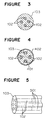
- FIG. 3 there is shown a cross-sectional view of the essential parts of the radiation detector according to a third embodiment of the present invention.
- a plurality of scintillation fibers 102 are arranged in the scattering member 103 to offer advantages similar to the first embodiment.
- the provision of the plurality of scintillation fiber 102 can further increase the probability that the radiations interact with the scintillation fibers 102.
- a light receiving amount per one pulse can be increased to obtain an advantage similar to an increase in the fluorescent amount by connecting a single photodetector to one end or opposite ends of the collection of the scintillation fibers.
- FIG 4 there is shown a cross-sectional view of the essential parts of the radiation detector according to a fourth embodiment of the present invention.
- the scattering member 103 which emits electrons by interaction with the radiation have grooves 401 formed therein, and the grooves 401 have the scintillation fibers 102 arranged therein.
- the scattering member 103 have a shade tape 402 arranged thereon to prevent disturbance light from entering the scintillation fiber 102, thereby avoiding reaction with light irrelevant to radiations to be measured.
- Such arrangement can protect the scintillation fibers 102 against an external pressure to prevent the scintillation fibers from being damaged or broken on and after installation.
- FIG 5 there is shown a schematic view of the essential parts of the radiation detector according to a fifth embodiment of the present invention.
- reference numeral 501 designates optical fibers for transmission which have lower transmission loss than the scintillation fibers 102, and which constitute the radiation detecting unit using the scintillation fibers 102.
- the optical fibers for transmission 501 are connected to one end or opposite ends of each scintillation fiber 102.
- the radiation detector thus constructed have one end or each end connected to a measuring unit which detects scintillation light caused by a radiation.
- the optical fibers for transmission 501 are made of a material which causes no reaction even if a radiation is incident thereon.
- the scintillation fibers generally have great transmission loss, and the scintillation fibers alone are difficult to carry out a wide range of measurement as the detecting unit.
- the scattering member 103 is arranged to surround the scintillation fiber 102, and the optical fibers for transmission 501 are connected to the scintillation fibers to restrain the transmission loss in the scintillation fibers 102 by a reduction in the length of the scintillation fibers.
- the optical fibers for transmission 501 are quarts fibers having low transmission loss. Connection between the scintillation fibers and the optical fibers may be made by use of a silicone adhesive agent, or by use of connectors having low connection loss such as F01 type connectors under Japanese Industrial Standard.
- Such arrangement can offer advantages similar to the first embodiment and enable further long-distance transmission.
- the radiation detecting unit and the measuring unit can be remotely installed to realize telemetering.
- FIG 6 there is shown a schematic view explaining how to connect a scintillation fiber and an optical fiber for transmission in the radiation detector according to a sixth embodiment of the present invention.
- reference numeral 601 designates inner connection pipes which have respective inner diameters identical to respective outer diameter of the scintillation fiber 102 and the optical fiber for transmission 501. These inner connection pipes 601 have the same outer diameter in this embodiment.
- Reference numeral 602 designates an outer connection pipe which has the same outer diameter as those of the inner connection pipes 601. Light from the scintillation fiber 102 can be effectively directed to the optical fiber for transmission 501 by aligning the center axes of the scintillation fiber 102, the optical fiber for transmission 501, the inner connection pipes 601 and the outer connection pipe 602.
- the scintillation fiber 102 and the optical fiber for transmission 501 are inserted into the respective inner connection pipes 601.
- the scintillation fiber and the optical fiber for transmission are fixed to the inner connection pipes 601 by use of e.g. an adhesive agent so that the inner connection pipes have connecting end surfaces flush with connecting end surfaces of the fibers 102 and 501.
- connection pipe 601 with the scintillation fiber 102 inserted therein and the inner connection pipe 601 with the optical fiber for transmission 501 inserted therein are inserted into the outer connection pipe 602 having the inner diameter identical to the outer diameters of the inner connection pipes 601.
- an optical cement is applied to the end surfaces of the respective fibers, and the fibers are fixed so as to have the end surface bonded together.
- FIG 7 there is shown a schematic view explaining how to connect a scintillation fiber and an optical fiber for transmission in the radiation detector according to a seventh embodiment of the present invention.
- reference numeral 701 designates an inner connection pipe which has an inner diameter identical to the outer diameter of the scintillation fiber 102.
- Reference numeral 702 designates another inner connection pipe which has an inner diameter identical to the outer diameter of the optical fiber for transmission 501.
- Reference numeral 703 designates an outer connection pipe which has the inner diameter of a part formed to be identical to the outer diameter of the outer connection pipe 701, and the inner diameter of the other part formed to be identical to the outer diameter of the inner connection pipe 702.
- Light from the scintillation fiber 102 can be effectively directed to the optical fiber for transmission 501 by aligning the center axes of the scintillation fiber 102, the optical fiber for transmission 501, the inner connection pipe 701, the inner connection pipe 702 and the outer connection pipe 703.
- the scintillation fiber 102 and the optical fiber for transmission 501 are inserted into the inner connection pipe 701 and the inner connection pipe 702, respectively.
- the scintillation fiber and the optical fiber for transmission are fixed to the inner connection pipes by use of e.g. an adhesive agent so that the inner connection pipes 701 and 702 have connecting end surfaces flush with the connecting end surfaces of the fibers 102 and 501.
- the inner connection pipe 701 with the scintillation fiber 102 inserted therein and the inner connection pipe 702 with the optical fiber for transmission 501 inserted therein are inserted into the outer connection pipe 703.
- an optical cement is applied to the end surfaces of the fibers, and the fibers are fixed so as to have the end surfaces bonded together.
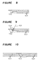
- FIG 8 there is shown a schematic view of the essential parts of the radiation detector according to an eighth embodiment of the present invention.
- a plurality of scintillation fibers 102 are arranged in or on the scattering member (not shown), and the respective scintillation fibers 102 are connected to optical fibers for transmission 501, the locations of the respective scintillation fibers 102 are shifted in a longitudinal direction so as to prevent the scintillation fibers from overlapping as shown in Figure 8.
- Such arrangement can arrange the radiation detecting unit in a wide range to carry out radiation monitoring in a wide range with transmission loss of fluorescent minimized.
- FIG 9 there is shown a schematic view of the essential parts of the radiation detector according to a ninth embodiment of the present invention.
- the scintillation fibers 102 are shifted in a longitudinal direction so as to have at least two of the scintillation fibers overlapped in the longitudinal direction as shown in Figure 9 though the scintillation fibers 102 are arranged not to overlap in the longitudinal direction in the eighth embodiment.
- Such arrangement can arrange the radiation detecting portion in a wide range, and increase the probability of the interaction between a radiation and the scintillation fibers 102 to raise sensitivity.
- FIG 10 there is shown a schematic view of the essential parts of the radiation detector according to a tenth embodiment of the present invention.
- the respective scintillation fibers 102 may have opposite ends connected to the optical fibers for transmission 501 in some radiation detecting systems as shown in Figure 10, though each scintillation fiber 102 has one end connected to an optical fiber for transmission 501 in the eighth embodiment and the ninth embodiment.
- the scintillation fibers 102 are shifted in a longitudinal direction so as not to prevent from overlapping in the longitudinal direction in Figure 10, the scintillation fibers may be arranged so as to overlap like the ninth embodiment. Such arrangement can utilize fluorescence which is transmitted in opposite directions of the scintillation fibers.
- the incident position of a radiation can be measured based on the time difference of fluorescent pulses which are detected at opposite end of the detecting portion.
- the scattering member 103 which emits an electron by interaction with a radiation is made of a noncombustible material such as iron or copper, and the scintillation fiber 102 is made of a quartz material with cerium filled charged therein in the radiation detectors provided according to the respective embodiments.
- a radiation detector having a fire-resistant property and a high-temperature-resistant property.
- FIG 11 there is shown a schematic view of the essential parts of the radiation detector according to a twelfth embodiment of the present invention.
- reference numeral 1101 designates scintillation fibers which are spirally arranged on the scattering member 103, or composite fibers constituted by scintillation fibers and optical fibers for transmission.
- the sensitivity of the scintillation fibers 102 as the radiation detecting portion is different depending on the incident direction of a radiation.
- the sensitivity of the respective scintillation fibers 102 can be equalized in respective spiral pitches.
- such spiral arrangement of the scintillation fibers can prevent stress from concentrating on the location of the scintillation fibers or the optical fibers for transmission even if bending stress is applied to the radiation detecting portion including the scattering member 103.
- FIG 12 there is shown a cross-sectional view of the essential parts of the radiation detector according to a thirteenth embodiment of the present invention.
- reference numeral 1201 designates a heat insulating tape.
- Reference numeral 1202 designates a shade tape.
- the scintillation fibers 102 are arranged in the scattering member 103.
- the scattering member 103 with the scintillation fibers 102 arranged therein is wound with the shade tape 1202, e.g. a way to coat the tape by application of heat may be adopted.
- the scintillation fibers 102 have a temperature raised to above the softing point thereof. In such a case, the characteristics of the scintillation fibers 102 may be changed.
- the heat insulating tape 1201 is arranged between the scattering member 103 and the shade tape 1202 as shown to prevent the scintillation fibers 102 from changing in terms of the characteristics thereof or being deformed, and to avoid heat deterioration by application of heat.
- FIGs 13(a)-(c) there are shown a cross-sectional view and explanatory diagrams of the essential parts of the radiation detector according to a fourteenth embodiment of the present invention.
- reference numerals 1301, 1302, 1303 and 1304 designate scintillation fibers.
- Reference numeral 1305 designates scattering members which are made of different materials.
- the scattering member 103 has a plurality of grooves formed therein to arrange the scintillation fibers 1301-1304 therein.
- the scattering members 1305 which are made of different materials are arranged to surround the respective scintillation fibers.
- the materials (atomic number and density) of the scattering members 1305 which are arranged to surround the respective scintillation fibers 1301-1304 can vary from one to another to make the sensitivity (energy characteristics) of the respective scintillation fibers 1301-1304 different. The presence of such different sensitivities is shown in Figure 13(b). Curves A, B, C and D designate the energy characteristics of the respective scintillation fibers 1301-1304. Although signal outputs from the respective scintillation fibers 1301-1304 may be detected by different measuring units, all scintillation fiber signals may be detected by a single measuring unit.
- the energy characteristics of a radiation to be measured are a superposition of the energy characteristics of the respective scintillation fibers as shown in Figure 13(c).
- the measuring unit may be connected to only one end or opposite ends of the radiation detecting portion. Such arrangement can obtain energy characteristics having flat sensitivity by a suitable combination of the scattering elements made of different materials.
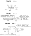
- FIG 14(a) there is shown a cross-sectional view of the essential parts of the radiation detector according to a fifteenth embodiment of the present invention.
- Figures 14(b) and (c) there are shown explanatory diagrams explaining how to transmit light.
- reference numeral 1401 designates an optical element which is arranged between a scintillation fiber 102 and an optical fiber for transmission 501, and which has a light-gathering function.
- the optical element 1401 may comprise e.g. a distribution refractive index type lens.
- the optical element is fixed to the end surfaces of the respective fibers by use of e.g. an optical cement.
- the inner connection pipes 601 which are put on connecting ends of the respective fibers have the same outer diameter.
- Reference numeral 602 designates an outer connection pipe which has the same inner diameter as the outer diameters of the respective inner connection pipes 601 and the outer diameter of the optical element 1401.
- the optical element 1401, the scintillation fiber 102, the optical fiber for transmission 501, the inner connection pipes 601 and the outer connection pipe 602 have center axes aligned one another.
- lack of the optical element 1401 with a light-gathering function allows light to be incident on the optical fiber for transmission 501 at an angel above the numerical aperture of the optical fiber when a light signal is transmitted from the scintillation fiber 102 to the optical fiber 501.
- Such cases occur when the numeral aperture of the scintillation fiber 102 is larger than that of the optical fiber 501. In such cases, part of the light which goes out of the scintillation fiber 102 can not be confined in the optical fiber for transmission 501, and such part goes out of the optical fiber 501 to fail to reach a measuring unit.
- the optical element 1401 which has a light-gathering function to have a large numerical aperture at the incident side of light and a low numerical aperture at the outgoing side of light, is arranged between the scintillation fiber 102 and the optical fiber for transmission 501 to match the numerical aperture at the outgoing side with the numerical aperture of the optical fiber for transmission 501.
- reference numeral 1501 designates optical fiber cables for transmission with plurality of optical fibers for transmission housed therein.
- Reference numeral 1502 designates a radiation detecting portion which includes a plurality of scintillation fibers 102 and the scattering member 103.
- Reference numeral 1503 designates the scintillation fibers arranged on the scattering member 103, or composite fibers constituted by a scintillation fiber and an optical fiber for transmission and arranged on the scattering member 103. Even if a radiation is incident on the optical fibers for transmission, the optical fibers for transmission do not react with the radiation.
- the scintillation fibers are difficult to carry out a wide range of measurement as a radiation detecting portion by themselves since the scintillation fibers generally have great transmission loss.
- the scintillation fibers are connected to the optical fibers for transmission to restrain the transmission loss in the scintillation fibers by reduction in the length of the scintillation fibers.
- the scattering member 103 is arranged only at the radiation detecting portion 1502, and no scattering member 103 is arranged on the optical fibers for transmission other than the optical fibers for transmission arranged in the radiation detecting portion although in the fifth embodiment the optical fibers for transmission are connected in the scattering member 103.
- the radiation detecting portion 1502 and the optical fiber cables for transmission 1501 are connected by e.g. a multiconductor connector or by bonding.
- Such arrangement can separate the manufacture of the radiation detecting portion 1502 and the manufacture of the optical fiber cables for transmission 1501 to shorten the production time and reduce cost.
- the absence of the scattering member 103 in the optical fiber cables for transmission 1501 can reduce the expense incurred for the scattering member.
Abstract
Description
Claims (10)
- A scintillation fiber used radiation detector comprising:at least one scintillation fiber (102, 1301, 1302, 1303, 1304, 1101 or 1503) for producing a light pulse in response to a radiation (101), the light pulse being detected at one end or opposite ends of the scintillation fiber to obtain radiation information; andat least one scattering member (103 or 1305) for emitting an electron (106) by interaction with the radiation;
wherein the scintillation fiber is arranged in or on the scattering member. - A scintillation fiber used radiation detector according to Claim 1, wherein the scattering member (103 or 1305) has at least one groove (401) formed therein, and the scintillation fiber (102, 1301, 1302, 1303, 1304, 1101 or 1503) is arranged in the groove.
- A scintillation fiber used radiation detector according to Claim 1, wherein the scintillation fiber (102, 1301, 1302, 1303, 1304, 1101 or 1503) is connected to an optical fiber for transmission (501) having lower transmission loss than the scintillation fiber.
- A scintillation fiber used radiation detector according to Claim 3, wherein the scintillation fiber (102, 1301, 1302, 1303, 1304, 1101 or 1503) and the optical fiber (501) have connecting ends covered by inner connection pipes (601, 701 or 702) so that the inner connection pipes have connecting end surfaces arranged to be flush with connecting end surfaces of the scintillation fiber and the optical fiber, the inner connection pipes having respective inner diameters identical to respective outer diameters of the scintillation fiber and the optical fiber, and the scintillation fiber and the optical fiber are connected by inserting the inner connection pipes in a single outer connection pipe (602 or 703) having respective inner diameters identical to respective outer diameters of the respective inner connection pipes.
- A scintillation fiber used radiation detector according to Claim 3, wherein the scintillation fiber (102, 1301, 1302, 1303, 1304, 1101 or 1503) and the optical fiber for transmission (501) have connecting ends covered by inner connection pipes (601, 702 or 703) so that the inner connection pipes have connecting end surfaces arranged to be flush with connecting end surfaces of the scintillation fiber and the optical fiber, the inner connection pipes having respective inner diameters identical to respective outer diameters of the scintillation fiber and the optical fiber, and the scintillation fiber and the optical fiber are connected by inserting the inner connection pipes in a single outer connection pipe (602 or 703) having respective inner diameters identical to respective outer diameters of the respective inner connection pipes, and interposing an optical element (1401) having a light-gathering function between the scintillation fiber and the optical fiber.
- A scintillation fiber used radiation detector according to Claim 3, wherein a plurality of scintillation fibers (102, 1301, 1302, 1303, 1304, 1101 or 1503) and a plurality of optical fibers for transmission (501) are connected to provide a plurality of composite fibers, and the composite fibers are arranged to have a portion with the scintillation fiber included therein relatively shifted in a longitudinal direction thereof.
- A scintillation fiber used radiation detector according to Claim 3, wherein the scintillation fiber (102, 1301, 1302, 1303, 1304, 1101 or 1503) and the optical fiber for transmission (501) are connected to provide a composite fiber, and the composite fiber has only a portion with the scintillation fiber included therein as a radiation detecting portion (1502) provided with the scattering member (103 or 1305) , and a light signal from the radiation detecting portion is transmitted through the optical fiber.
- A scintillation fiber used radiation detector according to Claim 1, wherein the scattering member (103 or 1305) is made of a noncombustible material, and the scintillation fiber (102, 1301, 1302, 1303, 1304, 1101 or 1503) is made of a quartz material.
- A scintillation fiber used radiation detector according to Claim 1, wherein the scintillation fiber (102, 1301, 1302, 1303, 1304, 1101 or 1503) is spirally arranged in or on the scattering member (103 or 1305).
- A scintillation fiber used radiation detector according to Claim 1, wherein the scattering member (103 or 1305) with the scintillation fiber (102, 1301, 1302, 1303, 1304, 1101 or 1503) arranged therein or thereon is wound by a heat insulating tape (1201).
Applications Claiming Priority (3)
| Application Number | Priority Date | Filing Date | Title |
|---|---|---|---|
| JP8350170A JPH10186034A (en) | 1996-12-27 | 1996-12-27 | Radiation detector using scintillation fiber |
| JP35017096 | 1996-12-27 | ||
| JP350170/96 | 1996-12-27 |
Publications (3)
| Publication Number | Publication Date |
|---|---|
| EP0851242A2 true EP0851242A2 (en) | 1998-07-01 |
| EP0851242A3 EP0851242A3 (en) | 2002-01-30 |
| EP0851242B1 EP0851242B1 (en) | 2005-03-02 |
Family
ID=18408698
Family Applications (1)
| Application Number | Title | Priority Date | Filing Date |
|---|---|---|---|
| EP97111645A Expired - Lifetime EP0851242B1 (en) | 1996-12-27 | 1997-07-09 | Radiation detector using scintillation fibers |
Country Status (7)
| Country | Link |
|---|---|
| US (1) | US5880475A (en) |
| EP (1) | EP0851242B1 (en) |
| JP (1) | JPH10186034A (en) |
| CN (1) | CN1088844C (en) |
| DE (1) | DE69732614T2 (en) |
| ES (1) | ES2238706T3 (en) |
| TW (1) | TW342454B (en) |
Cited By (5)
| Publication number | Priority date | Publication date | Assignee | Title |
|---|---|---|---|---|
| EP1103826A2 (en) | 1999-11-29 | 2001-05-30 | General Electric Company | High resolution and high luminance scintillator and radiation imager employing the same |
| WO2002046727A2 (en) * | 2000-12-05 | 2002-06-13 | Ge Medical Systems Global Technology Company, Llc | Apparatus and method of converting electromagnetic energy directly to electrons for computed tomography imaging |
| US7368722B2 (en) | 2004-02-25 | 2008-05-06 | Berthold Technologies Gmbh & Co. Kg | Method and apparatus for detecting ionizing radiation |
| WO2018218361A1 (en) | 2017-05-31 | 2018-12-06 | The Royal Institution For The Advancement Of Learning/Mcgill University | Non-invasive measurement of arterial input function for positron emission tomography imaging |
| FR3100343A1 (en) * | 2019-09-02 | 2021-03-05 | Centre National De La Recherche Scientifique | DOSIMETER |
Families Citing this family (55)
| Publication number | Priority date | Publication date | Assignee | Title |
|---|---|---|---|---|
| US6648552B1 (en) * | 1999-10-14 | 2003-11-18 | Bechtel Bwxt Idaho, Llc | Sensor system for buried waste containment sites |
| US8565860B2 (en) | 2000-08-21 | 2013-10-22 | Biosensors International Group, Ltd. | Radioactive emission detector equipped with a position tracking system |
| US8489176B1 (en) | 2000-08-21 | 2013-07-16 | Spectrum Dynamics Llc | Radioactive emission detector equipped with a position tracking system and utilization thereof with medical systems and in medical procedures |
| US8036731B2 (en) * | 2001-01-22 | 2011-10-11 | Spectrum Dynamics Llc | Ingestible pill for diagnosing a gastrointestinal tract |
| US8909325B2 (en) | 2000-08-21 | 2014-12-09 | Biosensors International Group, Ltd. | Radioactive emission detector equipped with a position tracking system and utilization thereof with medical systems and in medical procedures |
| US7826889B2 (en) * | 2000-08-21 | 2010-11-02 | Spectrum Dynamics Llc | Radioactive emission detector equipped with a position tracking system and utilization thereof with medical systems and in medical procedures |
| CN1310617C (en) * | 2001-01-22 | 2007-04-18 | V-目标技术有限公司 | Ingestible pill |
| US6993376B2 (en) * | 2002-01-28 | 2006-01-31 | Testardi Louis R | Radiation measurement within the human body |
| US6713765B2 (en) | 2002-03-11 | 2004-03-30 | Galileo Scientific, Inc. | Scintillating fiber radiation detector for medical therapy |
| US20040116807A1 (en) * | 2002-10-17 | 2004-06-17 | Roni Amrami | Blood vessels wall imaging catheter |
| US20040204646A1 (en) * | 2002-11-04 | 2004-10-14 | V-Target Technologies Ltd. | Intracorporeal-imaging head |
| AU2003276658A1 (en) * | 2002-11-04 | 2004-06-07 | V-Target Technologies Ltd. | Apparatus and methods for imaging and attenuation correction |
| US7038211B2 (en) * | 2002-12-03 | 2006-05-02 | Universities Research Association, Inc. | Systems and methods for detecting x-rays |
| US6965709B1 (en) * | 2003-05-14 | 2005-11-15 | Sandia Corporation | Fluorescent optical position sensor |
| US6989541B2 (en) * | 2003-05-30 | 2006-01-24 | General Dynamics Advanced Information Systems, Inc. | Coincident neutron detector for providing energy and directional information |
| WO2008010227A2 (en) | 2006-07-19 | 2008-01-24 | Spectrum Dynamics Llc | Imaging protocols |
| US7968851B2 (en) * | 2004-01-13 | 2011-06-28 | Spectrum Dynamics Llc | Dynamic spect camera |
| US8571881B2 (en) | 2004-11-09 | 2013-10-29 | Spectrum Dynamics, Llc | Radiopharmaceutical dispensing, administration, and imaging |
| WO2005067383A2 (en) | 2004-01-13 | 2005-07-28 | Spectrum Dynamics Llc | Multi-dimensional image reconstruction |
| US9470801B2 (en) | 2004-01-13 | 2016-10-18 | Spectrum Dynamics Llc | Gating with anatomically varying durations |
| US8586932B2 (en) * | 2004-11-09 | 2013-11-19 | Spectrum Dynamics Llc | System and method for radioactive emission measurement |
| WO2007010537A2 (en) * | 2005-07-19 | 2007-01-25 | Spectrum Dynamics Llc | Reconstruction stabilizer and active vision |
| EP1778957A4 (en) * | 2004-06-01 | 2015-12-23 | Biosensors Int Group Ltd | Radioactive-emission-measurement optimization to specific body structures |
| US8280124B2 (en) | 2004-06-01 | 2012-10-02 | Spectrum Dynamics Llc | Methods of view selection for radioactive emission measurements |
| EP1827505A4 (en) * | 2004-11-09 | 2017-07-12 | Biosensors International Group, Ltd. | Radioimaging |
| US8615405B2 (en) | 2004-11-09 | 2013-12-24 | Biosensors International Group, Ltd. | Imaging system customization using data from radiopharmaceutical-associated data carrier |
| US8423125B2 (en) | 2004-11-09 | 2013-04-16 | Spectrum Dynamics Llc | Radioimaging |
| US9943274B2 (en) | 2004-11-09 | 2018-04-17 | Spectrum Dynamics Medical Limited | Radioimaging using low dose isotope |
| US9316743B2 (en) | 2004-11-09 | 2016-04-19 | Biosensors International Group, Ltd. | System and method for radioactive emission measurement |
| US20080260637A1 (en) * | 2004-11-17 | 2008-10-23 | Dalia Dickman | Methods of Detecting Prostate Cancer |
| US7872235B2 (en) | 2005-01-13 | 2011-01-18 | Spectrum Dynamics Llc | Multi-dimensional image reconstruction and analysis for expert-system diagnosis |
| US8644910B2 (en) | 2005-07-19 | 2014-02-04 | Biosensors International Group, Ltd. | Imaging protocols |
| US8837793B2 (en) | 2005-07-19 | 2014-09-16 | Biosensors International Group, Ltd. | Reconstruction stabilizer and active vision |
| US7705316B2 (en) * | 2005-11-09 | 2010-04-27 | Spectrum Dynamics Llc | Dynamic SPECT camera |
| US8204500B2 (en) | 2005-12-28 | 2012-06-19 | Starhome Gmbh | Optimal voicemail deposit for roaming cellular telephony |
| US7329857B1 (en) | 2006-03-01 | 2008-02-12 | Sandia Corporation | Side-emitting fiber optic position sensor |
| US8894974B2 (en) * | 2006-05-11 | 2014-11-25 | Spectrum Dynamics Llc | Radiopharmaceuticals for diagnosis and therapy |
| US7601966B2 (en) | 2006-06-28 | 2009-10-13 | Spectrum Dynamics Llc | Imaging techniques for reducing blind spots |
| EP1921465B1 (en) * | 2006-11-13 | 2017-12-20 | Kabushiki Kaisha Toshiba | Survey meter |
| US8610075B2 (en) | 2006-11-13 | 2013-12-17 | Biosensors International Group Ltd. | Radioimaging applications of and novel formulations of teboroxime |
| WO2008075362A2 (en) * | 2006-12-20 | 2008-06-26 | Spectrum Dynamics Llc | A method, a system, and an apparatus for using and processing multidimensional data |
| US8521253B2 (en) | 2007-10-29 | 2013-08-27 | Spectrum Dynamics Llc | Prostate imaging |
| US7791046B2 (en) * | 2008-05-20 | 2010-09-07 | The Charles Stark Draper Laboratory, Inc. | High efficiency fiber-optic scintillator radiation detector |
| WO2010060089A2 (en) * | 2008-11-24 | 2010-05-27 | The Charles Stark Draper Laboratory, Inc. | Discrimination-enhanced fiber-optic scintillator radiation detector |
| US8338788B2 (en) | 2009-07-29 | 2012-12-25 | Spectrum Dynamics Llc | Method and system of optimized volumetric imaging |
| WO2013179970A1 (en) | 2012-05-31 | 2013-12-05 | 株式会社クラレ | Cable and radiation measuring apparatus |
| JP5972086B2 (en) * | 2012-07-27 | 2016-08-17 | 株式会社熊谷組 | Scintillation fiber device and method for manufacturing scintillation fiber device |
| US8779352B2 (en) | 2012-09-28 | 2014-07-15 | Schlumberger Technology Corporation | Scintillator body with spiral surface scratches |
| JP6282044B2 (en) * | 2013-05-22 | 2018-02-21 | 鹿島建設株式会社 | Storage facility and storage method for radioactive pollutants |
| CN106291657A (en) * | 2015-05-25 | 2017-01-04 | 天津市技术物理研究所 | A kind of based on the radiant spectral analysis system closing bundle flash fiber |
| CN105044760A (en) * | 2015-06-10 | 2015-11-11 | 南开大学 | Distributed single-end reflection type on-line radioactivity detecting instrument based on scintillation optical fiber and detecting method thereof |
| GB2557067B (en) | 2015-09-15 | 2021-08-18 | Halliburton Energy Services Inc | Downhole photon radiation detection using scintillating fibers |
| FR3063550B1 (en) * | 2017-03-03 | 2020-12-25 | Fibermetrix | METHOD OF MEASURING AND REPRESENTATION OF THE LEVEL OF LOCAL IRRADIATION DOSES |
| CN107167831B (en) * | 2017-05-18 | 2019-03-05 | 哈尔滨工程大学 | It is a kind of can emission-type at a distance can distribution measuring amount of radiation detector |
| US11035964B1 (en) * | 2020-04-29 | 2021-06-15 | Jefferson Science Associates, Llc | Method and apparatus for radiation detection based on time-of-flight within optical fibers |
Citations (5)
| Publication number | Priority date | Publication date | Assignee | Title |
|---|---|---|---|---|
| GB2200984A (en) * | 1986-12-16 | 1988-08-17 | Optical Data Communications Lt | Fire optic ionizing radiation detector |
| US4788436A (en) * | 1986-12-24 | 1988-11-29 | Walter Koechner | Radiation sensitive optical fiber and detector |
| JPH06294871A (en) * | 1993-04-09 | 1994-10-21 | Toshiba Corp | Radiation intensity distribution measuring instrument |
| FR2717908A1 (en) * | 1994-03-23 | 1995-09-29 | Toshiba Kk | Multi-point nuclear radiation detection appts. |
| EP0740167A1 (en) * | 1995-04-27 | 1996-10-30 | Mitsubishi Denki Kabushiki Kaisha | Radiation detector and method of detecting radiation |
Family Cites Families (6)
| Publication number | Priority date | Publication date | Assignee | Title |
|---|---|---|---|---|
| JPS5750672A (en) * | 1980-09-11 | 1982-03-25 | Toshiba Corp | Radiation detector |
| JPS5776466A (en) * | 1980-10-29 | 1982-05-13 | Toshiba Corp | Radiation detector |
| JPS5992375A (en) * | 1982-11-19 | 1984-05-28 | Furukawa Electric Co Ltd:The | Radiation detecting method |
| JPS62116284A (en) * | 1985-11-15 | 1987-05-27 | Toshiba Corp | Plastic scintillation detector |
| US5266808A (en) * | 1992-07-15 | 1993-11-30 | Schott Fiber Optics Inc. | Particle detector and method using a helical array of scintillators |
| JPH0894758A (en) * | 1994-09-26 | 1996-04-12 | Mitsubishi Electric Corp | Distribution-type detector using scintillation fiber |
-
1996
- 1996-12-27 JP JP8350170A patent/JPH10186034A/en active Pending
-
1997
- 1997-04-15 TW TW086104817A patent/TW342454B/en active
- 1997-06-03 US US08/867,883 patent/US5880475A/en not_active Expired - Fee Related
- 1997-07-09 ES ES97111645T patent/ES2238706T3/en not_active Expired - Lifetime
- 1997-07-09 DE DE69732614T patent/DE69732614T2/en not_active Expired - Lifetime
- 1997-07-09 EP EP97111645A patent/EP0851242B1/en not_active Expired - Lifetime
- 1997-08-08 CN CN97117323A patent/CN1088844C/en not_active Expired - Fee Related
Patent Citations (5)
| Publication number | Priority date | Publication date | Assignee | Title |
|---|---|---|---|---|
| GB2200984A (en) * | 1986-12-16 | 1988-08-17 | Optical Data Communications Lt | Fire optic ionizing radiation detector |
| US4788436A (en) * | 1986-12-24 | 1988-11-29 | Walter Koechner | Radiation sensitive optical fiber and detector |
| JPH06294871A (en) * | 1993-04-09 | 1994-10-21 | Toshiba Corp | Radiation intensity distribution measuring instrument |
| FR2717908A1 (en) * | 1994-03-23 | 1995-09-29 | Toshiba Kk | Multi-point nuclear radiation detection appts. |
| EP0740167A1 (en) * | 1995-04-27 | 1996-10-30 | Mitsubishi Denki Kabushiki Kaisha | Radiation detector and method of detecting radiation |
Non-Patent Citations (1)
| Title |
|---|
| PATENT ABSTRACTS OF JAPAN vol. 1995, no. 01, 28 February 1995 (1995-02-28) -& JP 06 294871 A (TOSHIBA CORP), 21 October 1994 (1994-10-21) * |
Cited By (10)
| Publication number | Priority date | Publication date | Assignee | Title |
|---|---|---|---|---|
| EP1103826A2 (en) | 1999-11-29 | 2001-05-30 | General Electric Company | High resolution and high luminance scintillator and radiation imager employing the same |
| EP1103826A3 (en) * | 1999-11-29 | 2002-08-28 | General Electric Company | High resolution and high luminance scintillator and radiation imager employing the same |
| WO2002046727A2 (en) * | 2000-12-05 | 2002-06-13 | Ge Medical Systems Global Technology Company, Llc | Apparatus and method of converting electromagnetic energy directly to electrons for computed tomography imaging |
| WO2002046727A3 (en) * | 2000-12-05 | 2003-04-24 | Ge Med Sys Global Tech Co Llc | Apparatus and method of converting electromagnetic energy directly to electrons for computed tomography imaging |
| US7368722B2 (en) | 2004-02-25 | 2008-05-06 | Berthold Technologies Gmbh & Co. Kg | Method and apparatus for detecting ionizing radiation |
| WO2018218361A1 (en) | 2017-05-31 | 2018-12-06 | The Royal Institution For The Advancement Of Learning/Mcgill University | Non-invasive measurement of arterial input function for positron emission tomography imaging |
| EP3631516A4 (en) * | 2017-05-31 | 2021-01-20 | The Royal Institution for the Advancement of Learning / McGill University | Non-invasive measurement of arterial input function for positron emission tomography imaging |
| FR3100343A1 (en) * | 2019-09-02 | 2021-03-05 | Centre National De La Recherche Scientifique | DOSIMETER |
| WO2021043773A1 (en) | 2019-09-02 | 2021-03-11 | Centre National De La Recherche Scientifique | Dosimeter |
| US11914083B2 (en) | 2019-09-02 | 2024-02-27 | Centre National De La Recherche Scientifique | Dosimeter |
Also Published As
| Publication number | Publication date |
|---|---|
| DE69732614T2 (en) | 2005-12-29 |
| EP0851242A3 (en) | 2002-01-30 |
| CN1088844C (en) | 2002-08-07 |
| ES2238706T3 (en) | 2005-09-01 |
| CN1186362A (en) | 1998-07-01 |
| US5880475A (en) | 1999-03-09 |
| JPH10186034A (en) | 1998-07-14 |
| EP0851242B1 (en) | 2005-03-02 |
| DE69732614D1 (en) | 2005-04-07 |
| TW342454B (en) | 1998-10-11 |
Similar Documents
| Publication | Publication Date | Title |
|---|---|---|
| US5880475A (en) | Scintillation fiber type radiation detector | |
| US5629515A (en) | Radiation measuring system having scintillation detectors coupled by optical fibers for multipoint measurement | |
| JP2971358B2 (en) | Radiation measurement device | |
| US5434415A (en) | Radiation-detecting light-transmission apparatus | |
| EP0749020B1 (en) | Particle measuring apparatus, method for particle measurement, and nuclear power plant | |
| CN102422135B (en) | Radiometric measuring device | |
| US5675151A (en) | Distribution type detector using scintillation fibers | |
| US6511222B1 (en) | Temperature sensor with optical fibre | |
| US5264702A (en) | On-line tritium production monitor | |
| RU2653116C2 (en) | Fibers based segmented nuclear level meter | |
| CN101556331A (en) | Optical fiber coupling organic scintillating fiber pulse neutron probe | |
| CN110146913A (en) | A kind of double clad flash fiber structure for extra long distance radiation sensing | |
| US5552880A (en) | Optical radiation probe | |
| JPH06258446A (en) | Optical waveguide scintillator and scintillation detector | |
| JP2008309497A (en) | Fiber optic sensor | |
| CN215262041U (en) | Sensing optical cable | |
| CN115629133A (en) | Nuclear power equipment damage detection system based on fiber bragg grating acoustic emission sensor | |
| CN114325816A (en) | Underground detection device | |
| CN210514735U (en) | External fixed point type ultra-weak fiber grating strain optical cable | |
| JP2001311777A (en) | Thin radiation surface contamination detector | |
| CN209689741U (en) | A kind of partition type optical fiber vibration measuring system | |
| US11035964B1 (en) | Method and apparatus for radiation detection based on time-of-flight within optical fibers | |
| JPH0990047A (en) | Instrument for measuring intensity distribution of radiation | |
| CN212030466U (en) | High-sensitivity micro-bending detection device for pipeline | |
| CN117572483A (en) | Light guide device based on anti-cosmic ray detector and radioactivity detection equipment |
Legal Events
| Date | Code | Title | Description |
|---|---|---|---|
| PUAI | Public reference made under article 153(3) epc to a published international application that has entered the european phase |
Free format text: ORIGINAL CODE: 0009012 |
|
| AK | Designated contracting states |
Kind code of ref document: A2 Designated state(s): AT BE CH DE DK ES FI FR GB GR IE IT LI LU MC NL PT SE Kind code of ref document: A2 Designated state(s): DE ES FR GB |
|
| RIN1 | Information on inventor provided before grant (corrected) |
Inventor name: TSUTAKA, YOSHIKAZU Inventor name: OKA, TORU |
|
| PUAL | Search report despatched |
Free format text: ORIGINAL CODE: 0009013 |
|
| AK | Designated contracting states |
Kind code of ref document: A3 Designated state(s): AT BE CH DE DK ES FI FR GB GR IE IT LI LU MC NL PT SE |
|
| 17P | Request for examination filed |
Effective date: 20020304 |
|
| AKX | Designation fees paid |
Free format text: DE ES FR GB |
|
| 17Q | First examination report despatched |
Effective date: 20040402 |
|
| GRAP | Despatch of communication of intention to grant a patent |
Free format text: ORIGINAL CODE: EPIDOSNIGR1 |
|
| GRAS | Grant fee paid |
Free format text: ORIGINAL CODE: EPIDOSNIGR3 |
|
| GRAA | (expected) grant |
Free format text: ORIGINAL CODE: 0009210 |
|
| AK | Designated contracting states |
Kind code of ref document: B1 Designated state(s): DE ES FR GB |
|
| REG | Reference to a national code |
Ref country code: GB Ref legal event code: FG4D |
|
| REG | Reference to a national code |
Ref country code: IE Ref legal event code: FG4D |
|
| REF | Corresponds to: |
Ref document number: 69732614 Country of ref document: DE Date of ref document: 20050407 Kind code of ref document: P |
|
| REG | Reference to a national code |
Ref country code: GB Ref legal event code: 727 |
|
| REG | Reference to a national code |
Ref country code: ES Ref legal event code: FG2A Ref document number: 2238706 Country of ref document: ES Kind code of ref document: T3 |
|
| REG | Reference to a national code |
Ref country code: GB Ref legal event code: 727A |
|
| ET | Fr: translation filed | ||
| PLBE | No opposition filed within time limit |
Free format text: ORIGINAL CODE: 0009261 |
|
| STAA | Information on the status of an ep patent application or granted ep patent |
Free format text: STATUS: NO OPPOSITION FILED WITHIN TIME LIMIT |
|
| 26N | No opposition filed |
Effective date: 20051205 |
|
| REG | Reference to a national code |
Ref country code: GB Ref legal event code: 727H |
|
| REG | Reference to a national code |
Ref country code: GB Ref legal event code: 746 Effective date: 20070416 |
|
| PGFP | Annual fee paid to national office [announced via postgrant information from national office to epo] |
Ref country code: GB Payment date: 20120704 Year of fee payment: 16 |
|
| PGFP | Annual fee paid to national office [announced via postgrant information from national office to epo] |
Ref country code: FR Payment date: 20120719 Year of fee payment: 16 Ref country code: ES Payment date: 20120731 Year of fee payment: 16 Ref country code: DE Payment date: 20120704 Year of fee payment: 16 |
|
| GBPC | Gb: european patent ceased through non-payment of renewal fee |
Effective date: 20130709 |
|
| REG | Reference to a national code |
Ref country code: FR Ref legal event code: ST Effective date: 20140331 |
|
| PG25 | Lapsed in a contracting state [announced via postgrant information from national office to epo] |
Ref country code: GB Free format text: LAPSE BECAUSE OF NON-PAYMENT OF DUE FEES Effective date: 20130709 Ref country code: DE Free format text: LAPSE BECAUSE OF NON-PAYMENT OF DUE FEES Effective date: 20140201 |
|
| REG | Reference to a national code |
Ref country code: DE Ref legal event code: R119 Ref document number: 69732614 Country of ref document: DE Effective date: 20140201 |
|
| PG25 | Lapsed in a contracting state [announced via postgrant information from national office to epo] |
Ref country code: FR Free format text: LAPSE BECAUSE OF NON-PAYMENT OF DUE FEES Effective date: 20130731 |
|
| REG | Reference to a national code |
Ref country code: ES Ref legal event code: FD2A Effective date: 20140909 |
|
| PG25 | Lapsed in a contracting state [announced via postgrant information from national office to epo] |
Ref country code: ES Free format text: LAPSE BECAUSE OF NON-PAYMENT OF DUE FEES Effective date: 20130710 |