EP0851104A1 - Gas turbine with heat recovery steam generator for cooling the combustion chamber, then injecting downstream of the combustion zone - Google Patents
Gas turbine with heat recovery steam generator for cooling the combustion chamber, then injecting downstream of the combustion zone Download PDFInfo
- Publication number
- EP0851104A1 EP0851104A1 EP97810878A EP97810878A EP0851104A1 EP 0851104 A1 EP0851104 A1 EP 0851104A1 EP 97810878 A EP97810878 A EP 97810878A EP 97810878 A EP97810878 A EP 97810878A EP 0851104 A1 EP0851104 A1 EP 0851104A1
- Authority
- EP
- European Patent Office
- Prior art keywords
- steam
- combustion chamber
- cooling
- amount
- turbine
- Prior art date
- Legal status (The legal status is an assumption and is not a legal conclusion. Google has not performed a legal analysis and makes no representation as to the accuracy of the status listed.)
- Granted
Links
Images
Classifications
-
- F—MECHANICAL ENGINEERING; LIGHTING; HEATING; WEAPONS; BLASTING
- F01—MACHINES OR ENGINES IN GENERAL; ENGINE PLANTS IN GENERAL; STEAM ENGINES
- F01K—STEAM ENGINE PLANTS; STEAM ACCUMULATORS; ENGINE PLANTS NOT OTHERWISE PROVIDED FOR; ENGINES USING SPECIAL WORKING FLUIDS OR CYCLES
- F01K21/00—Steam engine plants not otherwise provided for
- F01K21/04—Steam engine plants not otherwise provided for using mixtures of steam and gas; Plants generating or heating steam by bringing water or steam into direct contact with hot gas
- F01K21/047—Steam engine plants not otherwise provided for using mixtures of steam and gas; Plants generating or heating steam by bringing water or steam into direct contact with hot gas having at least one combustion gas turbine
-
- F—MECHANICAL ENGINEERING; LIGHTING; HEATING; WEAPONS; BLASTING
- F02—COMBUSTION ENGINES; HOT-GAS OR COMBUSTION-PRODUCT ENGINE PLANTS
- F02C—GAS-TURBINE PLANTS; AIR INTAKES FOR JET-PROPULSION PLANTS; CONTROLLING FUEL SUPPLY IN AIR-BREATHING JET-PROPULSION PLANTS
- F02C3/00—Gas-turbine plants characterised by the use of combustion products as the working fluid
- F02C3/20—Gas-turbine plants characterised by the use of combustion products as the working fluid using a special fuel, oxidant, or dilution fluid to generate the combustion products
- F02C3/30—Adding water, steam or other fluids for influencing combustion, e.g. to obtain cleaner exhaust gases
-
- F—MECHANICAL ENGINEERING; LIGHTING; HEATING; WEAPONS; BLASTING
- F02—COMBUSTION ENGINES; HOT-GAS OR COMBUSTION-PRODUCT ENGINE PLANTS
- F02C—GAS-TURBINE PLANTS; AIR INTAKES FOR JET-PROPULSION PLANTS; CONTROLLING FUEL SUPPLY IN AIR-BREATHING JET-PROPULSION PLANTS
- F02C7/00—Features, components parts, details or accessories, not provided for in, or of interest apart form groups F02C1/00 - F02C6/00; Air intakes for jet-propulsion plants
- F02C7/12—Cooling of plants
- F02C7/16—Cooling of plants characterised by cooling medium
-
- F—MECHANICAL ENGINEERING; LIGHTING; HEATING; WEAPONS; BLASTING
- F05—INDEXING SCHEMES RELATING TO ENGINES OR PUMPS IN VARIOUS SUBCLASSES OF CLASSES F01-F04
- F05D—INDEXING SCHEME FOR ASPECTS RELATING TO NON-POSITIVE-DISPLACEMENT MACHINES OR ENGINES, GAS-TURBINES OR JET-PROPULSION PLANTS
- F05D2260/00—Function
- F05D2260/20—Heat transfer, e.g. cooling
- F05D2260/232—Heat transfer, e.g. cooling characterized by the cooling medium
- F05D2260/2322—Heat transfer, e.g. cooling characterized by the cooling medium steam
-
- Y—GENERAL TAGGING OF NEW TECHNOLOGICAL DEVELOPMENTS; GENERAL TAGGING OF CROSS-SECTIONAL TECHNOLOGIES SPANNING OVER SEVERAL SECTIONS OF THE IPC; TECHNICAL SUBJECTS COVERED BY FORMER USPC CROSS-REFERENCE ART COLLECTIONS [XRACs] AND DIGESTS
- Y02—TECHNOLOGIES OR APPLICATIONS FOR MITIGATION OR ADAPTATION AGAINST CLIMATE CHANGE
- Y02E—REDUCTION OF GREENHOUSE GAS [GHG] EMISSIONS, RELATED TO ENERGY GENERATION, TRANSMISSION OR DISTRIBUTION
- Y02E20/00—Combustion technologies with mitigation potential
- Y02E20/16—Combined cycle power plant [CCPP], or combined cycle gas turbine [CCGT]
Abstract
Description
Die vorliegende Erfindung betrifft ein Verfahren gemäss Oberbegriff
des Anspruchs 1.The present invention relates to a method according to the preamble
of
Es ist üblich, zur Kühlung von thermisch hochbelasteten Aggregaten einer Gasturbogruppe, beispielsweise einer Brennkammer, Druckluft einzusetzen, welche intermediär oder nach erfolgter Kompression zu diesem Zweck abgezweigt wird. Nun ist es aber so, dass in modernen Gasturbinen zur Erzielung einer schadstoffarmen Verbrennung bei maximiertem Wirkungsgrad der Brennstoff mit möglichst der gesamten Verdichterluft vorgemischt werden sollte. Luftverluste, wie sie bei den bekanntgewordenen Luftkühlungen der thermisch hochbelasteten Aggregate entstehen, sind deshalb zu vermeiden. Eine weitere Problematik bei solchen Luftkühlungen besteht darin, dass die thermisch verbrauchte Luft jeweils an passender Stelle in den Turbinenprozess rückgeführt werden muss, wobei eine Luftmenge, welche beispielsweise die Turbine gekühlt hat, dann nicht ohne weiteres als Kühlmedium in die Brennkammer geleitet werden kann, da dort regelmässig höhere Drücke vorherrschen. Demnach geht bei der Rückführung dieser Kühlluft in den Turbinenprozess immer Kühlpotential verloren, das mit anderen Mitteln ersetzt werden muss.It is common for cooling thermally highly stressed Aggregates of a gas turbine group, for example a combustion chamber, To use compressed air, which is intermediate or after compression is branched off for this purpose. Now but it is the case that in modern gas turbines to achieve low-pollution combustion with maximized efficiency the fuel with as much of the compressor air as possible should be premixed. Air losses, as in the known air cooling of the thermally highly stressed Aggregates are therefore to be avoided. Another The problem with such air cooling is that the thermally used air in a suitable place in the Turbine process must be recycled, an amount of air, which has cooled the turbine, for example not easily passed into the combustion chamber as a cooling medium can, because there are regularly higher pressures. Accordingly, this cooling air goes in when it is recirculated the turbine process always lost cooling potential with that other means must be replaced.
Diese Ausgangslage akzentuiert sich zum Beispiel, wenn die Gasturbogruppe für eine sequentielle Befeuerung ausgelegt ist.This starting point is accentuated, for example, when the Gas turbine group designed for sequential firing is.
Bei Gasturbogruppen, die in Kombination mit einem nachgeschalteten Dampfkreislauf betrieben werden, ist man dazu übergangen, ein ohnehin zur Verfügung stehender Dampf für die Kühlung der thermisch hochbelasteten Aggregate einzusetzen, ausgehend von der Tatsache, dass die zur Verfügung stehende Abwärme aus einer letzten Gasturbine mehr Dampf zu erzeugen vermag, als zum Betrieb der zum Dampfkreislauf gehörenden Dampfturbine notwendig ist. Es ist bekanntgeworden, diesen zur freien Verfügung stehenden Dampf zur Leistungssteigerung in den Gasturbinenprozess einzuführen. Dabei wird aus thermodynamischen und strömungstechnischen Ueberlegungen darauf geachtet, dass die Beimischung mit der Verbrennungsluft die Verbrennung als solche nicht beeinträchtigen kann. Dies führt aber regelmässig zu komplizierten Eindüsungstechniken, die nicht zuletzt mit der Gemischbildung zweier in Temperatur, Druck und Verhalten unterschiedlicher Medien im Zusammenhang stehen. Danebst darf nicht unerwähnt bleiben, dass hier die Brennstoffregelung äusserst diffizil zu handhaben ist.For gas turbine groups, which in combination with a downstream Steam cycle are operated, one is ignored, an already available steam for the Use cooling of the thermally highly loaded units, based on the fact that the available Waste heat from a last gas turbine to generate more steam capable of operating the steam cycle Steam turbine is necessary. It has become known free steam to increase performance to introduce into the gas turbine process. Thereby thermodynamic and fluidic considerations on it paid attention that the admixture with the combustion air the Can not affect combustion as such. this leads to but regularly to complicated injection techniques that not least with the mixture formation of two in temperature, Pressure and behavior of different media in context stand. In addition, it should not go unmentioned that the Fuel control is extremely difficult to handle.
Hier will die Erfindung Abhilfe schaffen. Der Erfindung, wie sie in den Ansprüchen gekennzeichnet ist, liegt die Aufgabe zugrunde, bei einem Verfahren der eingangs genannten Art die freie zur Verfügung stehende Dampfmenge weiternutzend zu verwenden, dergestalt, dass deren anschliessende Zumischung an passender Stelle in die Gasturbogruppe die Verbrennung in der Brennkammer nicht zu beeinträchtigt vermag.The invention seeks to remedy this. The invention how it is characterized in the claims, the task lies the basis for a procedure of the type mentioned at the beginning continue to use the free available amount of steam, in such a way that their subsequent admixture suitable place in the gas turbine group the combustion in the Combustion chamber is not too impaired.
Erfindungsgemäss soll die Kühlung der Brennkammer ausschliesslich mit einer Dampfmenge durchgeführt werden. Da dieser Dampf aus obigen Ueberlegungen frei zur Verfügung steht, soll er nicht in herkömmlicher Weise im Kreislauf geführt werden, sondern nach erfolgtem Kühlungszweck an passender Stelle in die Heissgasströmung der vorgängig gekühlten Brennkammer zugemischt werden, womit sich unter anderen die Konfiguration der Kühlelemente gegenüber einem an sich auch denkbaren geschlossenen Kühldampfkreislauf stark vereinfacht, da Dampfverluste bei dem erfindungsgemässen Vorschlag in einem gewissen Umfang in Kauf genommen werden können.According to the invention, the combustion chamber is to be cooled exclusively be carried out with a quantity of steam. There this steam is freely available from the above considerations stands, it should not be circulated in the conventional way are performed, but after the cooling purpose has been carried out on the appropriate Place in the hot gas flow of the previously cooled Combustion chamber are mixed, which among other things Configuration of the cooling elements compared to one in itself conceivable closed cooling steam cycle greatly simplified, since steam losses in the inventive proposal in can be accepted to a certain extent.
Die passende Stelle für die Zumischung der vorgängig zu Kühlzwecken eingesetzten Dampfmenge steht in einer Interdependenz mit dem anvisierten Ziel, die Verbrennung mit minimierten Schadstoff-Emissionen, insbesondere was die NOx-Emissionen betrifft, zu bewerkstelligen. Durch eine magere Verbrennung sind niedrige NOx-Emissionen zu erwarten, so dass die Zumischung der vorgängig zu Kühlzwecken eingesetzten Dampfmenge einerseits losgelöst von dieser Verbrennung, andererseits nach erfolgtem vollständigem Ausbrand erfolgen soll, so dass damit auch die CO- und UHC-Emissionen minimiert werden können. Diese passende Stelle ist im letzten Drittel einer solchen Brennkammer lokalisiert. Die vorgeschlagene Dampfkühlung kann selbstverständlich bei jeder Brennkammer zur Anwendung gelangen; hier erfolgen dann die Korrekturen für eine optimale Eindüsung von Fall zu Fall durch die Bestimmung der hierzu passenden Stelle in Abhängigkeit zur Ausdehnung der Ausbrandzone der betreffenden Brennkammer.The right place for adding the previously for cooling purposes amount of steam used is in an interdependence with the aim of minimizing combustion Pollutant emissions, especially what the NOx emissions concerns to accomplish. Through a lean burn low NOx emissions are expected, so that the admixture the amount of steam previously used for cooling detached from this combustion on the one hand, on the other hand after complete burnout should take place, so that so that CO and UHC emissions can also be minimized. This suitable position is in the last third of such a position Localized combustion chamber. The proposed steam cooling can of course be used in every combustion chamber reach; Here the corrections are made for an optimal one Injection from case to case by determining the suitable position depending on the extension of the Burnout zone of the combustion chamber concerned.
Diese Zumischung kann dabei homogen über den Umfang verteilt erfolgen, da der Dampf durch die erfolgte Kühlung bereits umfangsmässig verteilt vorliegt. Ausserdem kann hier durch eine einfache Auslegung der Eindüsungsöffnungen stromauf der Turbine jenes optimale Brennkammeraustrittsprofil für deren Beaufschlagung erzeugt werden.This admixture can be distributed homogeneously over the circumference because the steam has already been cooled is distributed circumferentially. You can also go through here a simple design of the injection openings upstream of the Turbine that optimal combustion chamber outlet profile for their Loading are generated.
Die Kühlung lässt sich in Gleichstrom oder Gegenstrom zur Heissgasströmung durchführen. Eine Kombination der beiden Arten ist auch möglich. Des weiteren ist es ohne weiteres möglich, vorgängig der Kühlung der Brennkammer die Dampfmenge zu Kühlzwecken im geschlossenen Strömungspfad durch die Turbine strömen zu lassen. Dies ist hier nur möglich, weil die Druckverhältnisse zwischen Turbine und Dampfmenge eine solche Führung zulassen.The cooling can be done in cocurrent or countercurrent Carry out hot gas flow. A combination of the two Species is also possible. Furthermore, it is straightforward possible, prior to cooling the combustion chamber, the amount of steam for cooling purposes in the closed flow path through the turbine to flow. This is only possible here because the Pressure ratios between the turbine and the amount of steam such Allow leadership.
Vorteilhafte und zweckmässige Weiterbildungen der erfindungsgemässen Aufgabenstellung sind in den weiteren Ansprüchen gekennzeichnet.Advantageous and expedient developments of the inventive Task are in the further claims featured.
Im folgenden wird anhand der Figur ein Ausführungsbeispiel der Erfindung näher erläutert. Alle für das unmittelbare Verständnis der Erfindung nicht erforderlichen Elemente sind fortgelassen worden. Die Strömungrichtung der Medien ist mit Pfeilen angegeben.An exemplary embodiment is described below with reference to the figure the invention explained in more detail. All for immediate understanding are not necessary elements of the invention been left out. The direction of flow of the media is with Arrows indicated.
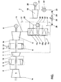
Die einzige Figur zweigt eine Kombinierte Gas/Dampf-Anlage (Kombianlage) mit der Führung einer Dampfmenge zu Kühlzwecken der thermisch belasteten resp. hochbelasteten Aggregate.The only figure branches off a combined gas / steam system (Combination system) with the guidance of a quantity of steam for cooling purposes the thermally stressed resp. highly loaded aggregates.
Die Figur zeigt eine Kombianlage, welche aus einer Gasturbogruppe
und einem nachgeschalteten Dampfkreislauf 7 besteht.
Die Gasturbogruppe selbst besteht aus einer Verdichtereinheit
1, einer der Verdichtereinheit 1 nachgeschalteten ersten
Brennkammer 2, im folgenden HD-Brennkammer genannt, einer
stromab dieser Brennkammer wirkenden HD-Turbine 3, einer der
HD-Turbine nachgeschalteten zweiten Brennkammer 4, im folgenden
ND-Brennkammer genannt, und einer stromab dieser Brennkammer
wirkenden ND-Turbine 5. Ein Generator 6 sorgt für die
Stromerzeugung. Die von der Verdichtereinheit 1 angesaugte
Luft 16 wird nach erfolgter Kompression als verdichtete Luft
8 in die HD-Brennkammer 2 geleitet. Diese Brennkammer 2 wird
mit einem Brennstoff 9 befeuert, der an sich gasförmig
und/oder flüssig sein kann, je nach Art des in dieser Brennkammer
eingesetzten Brenners. Brennkammern werden normalerweise
mit einem Diffusionsbrenner betrieben; diese Brennkammer
2 soll indessen vorzugsweise mit einem Vormischbrenner
betrieben werden, wie er in EP-B1-0 321 809 beschrieben ist,
wobei dieser Erfindungsgegenstand integrierender Bestandteil
dieser Beschreibung ist. Die Heissgase 10 aus der HD-Brennkammer
2 beaufschlagen zunächst die HD-Turbine 3. Dabei ist
diese Turbine 3 so ausgelegt, dass hier eine minimale Expansion
stattfindet, dergestalt, dass deren Abgase 11 eine verhältnismässig
hohe Temperatur aufweisen. Stromab dieser Turbine
3 befindet sich die ND-Brennkammer 4, welche im wesentlichen
die Form eines ringförmigen Zylinders hat. Diese
Brennkammer 4 weist keine herkömmliche Brennerkonfiguration
auf: Die Verbrennung geschieht hier durch Selbstzündung eines
in die heissen Abgase 11 eingedüsten Brennstoffes 13. Ausgehend
davon, dass es sich hier um einen gasförmigen Brennstoff,
also beispielsweise Erdgas, handelt, müssen für eine
Selbstzündung gewisse unabdingbare Voraussetzungen erfüllt
werden: Zunächst ist davon auszugehen, dass eine Selbstzündung
nach vorliegender Konstellation erst bei einer Temperatur
um die 1000°C vonstatten geht, und dies soll auch bei
Teillastbetrieb der Fall sein. Diese Forderung kann aber
gewichtig eine optimale thermodynamische Auslegung des
Gasturbinenprozesses negativ tangieren. Deshalb darf aus
thermodynamischen Gründen das Druckverhältnis der HD-Turbine
3 nicht so weit angehoben werden, dass sich daraus eine
niedrige Austrittstemperatur von beispielsweise ca. 500°C
ergibt, wie sie für einen sicheren Betrieb einer nachgeschalteten
konventionellen Brennkammer vorteilhaft wäre. Um eine
gesicherte Selbstzündung in der ND-Brennkammer 4 auch bei ungünstigen
Bedingungen zu gewährleisten, kann der in die ND-Brennkammer
4 eingedüste gasförmige Brennstoff 13 mit einer
Menge eines anderen Brennstoffes 12, der eine niedrige Zündtemperatur
aufweist, gemischt werden. Als Hilfsbrennstoff
eines gasförmigen Basisbrennstoffes eignet sich hier Oel vorzüglich.
Dieser flüssige Hilfsbrennstoff 12, entsprechend
eingedüst, fungiert sozusagen als Zündschnur, und ermöglicht
auch dann eine Selbstzündung in der ND-Brennkammer 4, wenn
die Abgase 11 aus der HD-Turbine 3 eine Temperatur aufweisen,
die unterhalb jener optimalen Selbstzündtemperatur liegt. Die
in der ND-Brennkammer 4 bereitgestellten Heissgase 14 beaufschlagen
anschliessend die ND-Turbine 5. Das kalorische
Potential der Abgase 15 aus dieser ND-Turbine 5 kann weitergehend
genutzt werden, beispielsweise durch Nachschaltung
eines Dampfkreislaufes 7 zur Bereitstellung einer Dampfmenge
zum Betreiben einer Dampfturbine und/oder Vorwärmung des Einspritzwassers.The figure shows a combination system, which consists of a gas turbine group
and a
Insbesondere bei einer solchen Konfiguration ist die thermische
Belastung der Brennkammern sowie der Turbinen recht
hoch, weshalb die Kühlung auch äusserst effizient ausfallen
muss. Dabei muss gleichzeitig noch berücksichtigt werden,
dass Gasturbogruppen dieser Hochleistungsstufe im allgemeinen
wenig Luft zu Kühlzwecken freistellen können, sollen der Wirkungsgrad
und die spezifische Leistung nicht markant sinken.
Die Kühlung der thermisch belasteten Aggregate kann aber vorteilhaft
durch Dampf geschehen, der bei dem hier nachgeschalteten
Dampfkreislauf 7 ohnehin in genügender Menge und Qualität
vorhanden ist. Ist ein solcher Dampfkreislauf nicht vorhanden,
so lässt sich die hierzu benötigte Dampfmenge leicht
anhand einer abgezweigten Teilmenge der Abwärme aus der letzten
Turbine bereitstellen.In particular with such a configuration, the thermal
Load the combustion chambers and the turbines right
high, which is why the cooling is also extremely efficient
got to. At the same time, it must also be taken into account
that gas turbine groups of this high performance level in general
Can provide little air for cooling purposes, the efficiency
and the specific performance does not decrease significantly.
The cooling of the thermally loaded units can, however, be advantageous
done by steam, the one downstream here
Die hochkalorischen Abgase 15 durchströmen einen Abhitzedampferzeuger
17 , in welchem in Wärmetauschverfahren Dampf
erzeugt wird, der das Arbeitsmedium für eine nachgeschaltete
mit einem Generator 20 gekoppelten Dampfturbine 18 bildet.
Die dann thermisch ausgenutzten Abgase strömen als Rauchgase
19 vorzugsweise über eine nicht dargestellte Reinigungsanlage
ins Freie. Möglich ist auch eine Weiternutzung dieser Rauchgase
zu anderen Zwecken. Selbstverständlich ist es auch möglich,
in Wirkverbindung mit dem Abhitzedampferzeuger 17 eine
Zwischenüberhitzung vorzunehmen. Der entspannte Dampf 21 aus
der genannten Dampfturbine 18 wird in einem wasser- oder
luftgekühlten Kondensator 22 kondensiert. Durch eine stromab
des Kondensators 22 angeordnete Förderpumpe 23 wird das Kondensat
24 in einen Speisewasserbehälter und Entgaser 25
gefördert. Durch Entnahme einer bestimmten Menge Anzapfdampf
aus der Dampfturbine 18 kann das zersprühte Kondensat 24 auf
Siedezustand gebracht und entgast werden. Eine weitere nachgeschaltete
Förderpumpe 26 pumpt dann das Wasser 27 durch den
Abhitzedampferzeuger 17. Zuerst durchläuft das Wasser 27 eine
ND-Dampferzeugung 17a, anschliessend strömt dieser Dampf in
eine Kesseltrommel 28. Im geschlossenen Kreislauf ist die
Kesseltrommel 28 mit einer MD-Dampferzeugung 17b verbunden,
dergestalt, dass hierein ein Sattdampf 29 entsteht, der dann
durch eine HD-Dampferzeugung 17c beschickt wird, in welcher
die qualitative Dampfbereitstellung für die Beaufschlagung
der Dampfturbine 18 geschieht.The high-
Zur Kühlung der Aggregate der Gasturbogruppe wird aus der
Kesseltrommel 28 eine überschüssige Dampfmenge 30 entnommen.
Durch Regelorgane lässt sich die benötigte Dampfmenge dann zu
den einzelnen Aggregate führen. In der Figur sind zwei
Kühldampfstränge 31, 32 ersichtlich. Mit der Dampfmenge 32
wird zunächst die HD-Turbine 3 im geschlossenen Strömungspfad,
d.h. ohne Zumischung, gekühlt, anschliessend wird mit
dieser Dampfmenge die Brennkammer 2, in Gleich- oder
Gegenstrom zur Heissgasströmung, gekühlt. Nach abgeschlossener
Kühlung wird die Dampfmenge dann an geeigneter Stelle,
vorzugsweise innerhalb des letzten Drittels dieser Brennkammer
der Heissgasströmung zugemischt. Damit lässt sich ohne
Beeinflussung der auf minimierte NOx-Emissionen ausgelegten
Verbrennung eine maximierte Leistungssteigerung der Anlage
erreichen. Darüber hinaus geschieht die Eindüsung thermodynamisch
und strömungstechnisch an optimaler Stelle, wobei ferner
mit dieser Vorkehrung eine gewichtige Reduzierung der aus
der Ausbrandzone verbleibenden CO- und UHC-Emissionen
erreicht wird. Die andere Dampfmenge 31 wird zu gleichen
Kühlzwecken, in analoger Weise zum oben beschriebenen Kühlungspfad
für die ND-Brennkammer 4 und ND-Turbine 5 eingesetzt.
Die Entnahme der hier benötigte Kühldampfmenge ist
nicht auf die Kesseltrommel 28 beschränkt.To cool the units of the gas turbine group, the
An excess amount of
Die zu kühlenden Aggregate 2, 3, 4, 5 lassen sich auch, im
Gegensatz zu den in der Figur gezeigten Serieschaltungen,
individuell kühlen, wobei dann die Zumischung der einzelnen
Dampfmenge in die Heissgasströmungen von Fall zu Fall vorgenommen
werden muss. Grundsätzlich ist hier eine individuelle
Zumischung der zu Kühlzwecken eingesetzten Dampfmenge in die
jeweilige Brennkammer, abströmungsseitig der Ausbrandzone,
auch möglich. Bei individueller Kühlung der thermisch hochbelasteten
Aggregate der Gasturbogruppe lassen sich sodann verschiedene
Dampfmenge zusammenfassen, bevor sie in die Brennkammern
2, 4 eingeleitet werden.The
- 11
- VerdichtereinheitCompressor unit
- 22nd
- Hochdruck-Brennkammer, HD-BrennkammerHigh pressure combustion chamber, HD combustion chamber
- 33rd
- Hochdruck-Turbine, HD-TurbineHigh pressure turbine, high pressure turbine
- 44th
- Niederdruck-Brennkammer, ND-Brennkammer Low pressure combustion chamber, LP combustion chamber
- 55
- Niederdruck-Brennkammer, ND-BrennkammerLow pressure combustion chamber, LP combustion chamber
- 66
- Generatorgenerator
- 77
- DampfkreislaufSteam cycle
- 88th
- Verdichtete LuftCompressed air
- 99
- Brennstofffuel
- 1010th
- HeissgaseHot gases
- 1111
- Heisse AbgaseHot exhaust gases
- 1212th
- HilfsbrennstoffAuxiliary fuel
- 1313
- 13 Brennstoff13 fuel
- 1414
- HeissgaseHot gases
- 1515
- 15 Abgase15 exhaust gases
- 1616
- AnsaugluftIntake air
- 1717th
- AbhitzedampferzeugerHeat recovery steam generator
- 17a17a
- Niederdruck-DampferzeugerLow pressure steam generator
- 17b17b
- Mitteldruck-DampferzeugerMedium pressure steam generator
- 17c17c
- Hochdruck-DampferzeugerHigh pressure steam generator
- 1818th
- DampfturbineSteam turbine
- 1919th
- RauchgaseFlue gases
- 2020th
- Generatorgenerator
- 2121
- Abdampf, Entspannter DampfSteam, relaxed steam
- 2222
- Kondensatorcapacitor
- 2323
- FörderpumpeFeed pump
- 2424th
- Kondensatcondensate
- 2525th
- Speisewasserbehälter und EntgaseFeed water tank and degassing
- 2626
- FörderpumpeFeed pump
- 2727
- Wasserwater
- 2828
- KesseltrommelBoiler drum
- 2929
- SattdampfSaturated steam
- 3030th
- KühldampfCooling steam
- 3131
- KühldampfpfadCooling steam path
- 3232
- KühldampfpfadCooling steam path
Claims (6)
Applications Claiming Priority (2)
| Application Number | Priority Date | Filing Date | Title |
|---|---|---|---|
| DE19654472 | 1996-12-27 | ||
| DE19654472A DE19654472A1 (en) | 1996-12-27 | 1996-12-27 | Process for cooling thermally highly loaded units of a gas turbine group |
Publications (2)
| Publication Number | Publication Date |
|---|---|
| EP0851104A1 true EP0851104A1 (en) | 1998-07-01 |
| EP0851104B1 EP0851104B1 (en) | 2002-09-18 |
Family
ID=7816289
Family Applications (1)
| Application Number | Title | Priority Date | Filing Date |
|---|---|---|---|
| EP97810878A Expired - Lifetime EP0851104B1 (en) | 1996-12-27 | 1997-11-18 | Gas turbine with heat recovery steam generator for cooling the combustion chamber, then injecting downstream of the combustion zone |
Country Status (4)
| Country | Link |
|---|---|
| US (1) | US6085514A (en) |
| EP (1) | EP0851104B1 (en) |
| JP (1) | JP4272718B2 (en) |
| DE (2) | DE19654472A1 (en) |
Cited By (2)
| Publication number | Priority date | Publication date | Assignee | Title |
|---|---|---|---|---|
| GB2357552A (en) * | 1999-12-20 | 2001-06-27 | Alstom Power | Mixed air and steam gas turbine coolant |
| US8671688B2 (en) | 2011-04-13 | 2014-03-18 | General Electric Company | Combined cycle power plant with thermal load reduction system |
Families Citing this family (26)
| Publication number | Priority date | Publication date | Assignee | Title |
|---|---|---|---|---|
| DE19846225C2 (en) * | 1998-10-07 | 2002-05-29 | Siemens Ag | Gas and steam turbine plant |
| DE19900026B4 (en) * | 1999-01-02 | 2016-01-21 | Alstom Technology Ltd. | Gas turbine with steam injection |
| DE19925356A1 (en) * | 1999-06-02 | 2000-12-07 | Asea Brown Boveri | Pure steam formation method e.g. for supplying steam turbine, involves separating wet steam into liquid phase containing impurities and pure steam before supplying latter to load |
| DE10041413B4 (en) * | 1999-08-25 | 2011-05-05 | Alstom (Switzerland) Ltd. | Method for operating a power plant |
| US6298656B1 (en) * | 2000-09-29 | 2001-10-09 | Siemens Westinghouse Power Corporation | Compressed air steam generator for cooling combustion turbine transition section |
| US8015818B2 (en) * | 2005-02-22 | 2011-09-13 | Siemens Energy, Inc. | Cooled transition duct for a gas turbine engine |
| DE102006029888B3 (en) * | 2006-06-28 | 2007-11-15 | Boge Kompressoren Otto Boge Gmbh & Co Kg | Compressor system for producing oil-free compressed air, has expansion machine transforming energy in form of heat into mechanical work for driving fan and electrical machine to realize heat dissipation of system |
| US9222410B2 (en) | 2011-04-13 | 2015-12-29 | General Electric Company | Power plant |
| US10520193B2 (en) | 2015-10-28 | 2019-12-31 | General Electric Company | Cooling patch for hot gas path components |
| US10520194B2 (en) | 2016-03-25 | 2019-12-31 | General Electric Company | Radially stacked fuel injection module for a segmented annular combustion system |
| US10563869B2 (en) | 2016-03-25 | 2020-02-18 | General Electric Company | Operation and turndown of a segmented annular combustion system |
| US10584876B2 (en) | 2016-03-25 | 2020-03-10 | General Electric Company | Micro-channel cooling of integrated combustor nozzle of a segmented annular combustion system |
| US10724441B2 (en) | 2016-03-25 | 2020-07-28 | General Electric Company | Segmented annular combustion system |
| US11428413B2 (en) | 2016-03-25 | 2022-08-30 | General Electric Company | Fuel injection module for segmented annular combustion system |
| US10584880B2 (en) | 2016-03-25 | 2020-03-10 | General Electric Company | Mounting of integrated combustor nozzles in a segmented annular combustion system |
| US10830442B2 (en) | 2016-03-25 | 2020-11-10 | General Electric Company | Segmented annular combustion system with dual fuel capability |
| US10605459B2 (en) | 2016-03-25 | 2020-03-31 | General Electric Company | Integrated combustor nozzle for a segmented annular combustion system |
| US10641491B2 (en) | 2016-03-25 | 2020-05-05 | General Electric Company | Cooling of integrated combustor nozzle of segmented annular combustion system |
| US11156362B2 (en) | 2016-11-28 | 2021-10-26 | General Electric Company | Combustor with axially staged fuel injection |
| US10690350B2 (en) | 2016-11-28 | 2020-06-23 | General Electric Company | Combustor with axially staged fuel injection |
| US10337357B2 (en) * | 2017-01-31 | 2019-07-02 | General Electric Company | Steam turbine preheating system with a steam generator |
| US11614233B2 (en) | 2020-08-31 | 2023-03-28 | General Electric Company | Impingement panel support structure and method of manufacture |
| US11371702B2 (en) | 2020-08-31 | 2022-06-28 | General Electric Company | Impingement panel for a turbomachine |
| US11460191B2 (en) | 2020-08-31 | 2022-10-04 | General Electric Company | Cooling insert for a turbomachine |
| US11255545B1 (en) | 2020-10-26 | 2022-02-22 | General Electric Company | Integrated combustion nozzle having a unified head end |
| US11767766B1 (en) | 2022-07-29 | 2023-09-26 | General Electric Company | Turbomachine airfoil having impingement cooling passages |
Citations (8)
| Publication number | Priority date | Publication date | Assignee | Title |
|---|---|---|---|---|
| FR343772A (en) * | 1903-06-12 | 1904-10-14 | Sebastian Ziani De Ferranti | Improvements to elastic fluid turbines |
| US3238719A (en) * | 1963-03-19 | 1966-03-08 | Eric W Harslem | Liquid cooled gas turbine engine |
| GB1140757A (en) * | 1965-10-29 | 1969-01-22 | Exxon Research Engineering Co | Improvements in gas turbine engines |
| GB2187273A (en) * | 1985-10-31 | 1987-09-03 | Bernard George Ediss | A gas turbine binary cycle |
| EP0314112A1 (en) * | 1987-10-27 | 1989-05-03 | Kabushiki Kaisha Toshiba | Combustor for gas turbine |
| EP0318706A1 (en) * | 1987-11-30 | 1989-06-07 | General Electric Company | Water spray ejector system for steam injected engine |
| GB2236145A (en) * | 1989-07-28 | 1991-03-27 | Gen Electric | Gas turbine engine steam cooling |
| EP0674099A1 (en) * | 1994-03-21 | 1995-09-27 | ABB Management AG | Cooling method for the thermically charged components of a gasturbine powerplant |
Family Cites Families (16)
| Publication number | Priority date | Publication date | Assignee | Title |
|---|---|---|---|---|
| FR963507A (en) * | 1947-03-21 | 1950-07-17 | ||
| US2770097A (en) * | 1952-02-14 | 1956-11-13 | William C Walker | Cooling systems for engines that utilize heat |
| CH456250A (en) * | 1966-05-06 | 1968-05-15 | Sulzer Ag | Process for the mixed gas and steam operation of a gas turbine system as well as system for carrying out the process |
| US3657884A (en) * | 1970-11-20 | 1972-04-25 | Westinghouse Electric Corp | Trans-nozzle steam injection gas turbine |
| US3747336A (en) * | 1972-03-29 | 1973-07-24 | Gen Electric | Steam injection system for a gas turbine |
| US4041699A (en) * | 1975-12-29 | 1977-08-16 | The Garrett Corporation | High temperature gas turbine |
| US4571935A (en) * | 1978-10-26 | 1986-02-25 | Rice Ivan G | Process for steam cooling a power turbine |
| US4550562A (en) * | 1981-06-17 | 1985-11-05 | Rice Ivan G | Method of steam cooling a gas generator |
| US4823546A (en) * | 1984-02-07 | 1989-04-25 | International Power Technology | Steam-injected free-turbine-type gas turbine |
| US4893467A (en) * | 1988-07-13 | 1990-01-16 | Gas Research Institute | Control system for use with steam injected gas turbine |
| US5170622A (en) * | 1991-04-02 | 1992-12-15 | Cheng Dah Y | Advanced regenerative parallel compound dual fluid heat engine Advanced Cheng Cycle (ACC) |
| US5329758A (en) * | 1993-05-21 | 1994-07-19 | The United States Of America As Represented By The Secretary Of The Navy | Steam-augmented gas turbine |
| US5461854A (en) * | 1993-07-07 | 1995-10-31 | Griffin, Jr.; Arthur T. | Combustor cooling for gas turbine engines |
| US5640840A (en) * | 1994-12-12 | 1997-06-24 | Westinghouse Electric Corporation | Recuperative steam cooled gas turbine method and apparatus |
| JP3196549B2 (en) * | 1995-01-09 | 2001-08-06 | 株式会社日立製作所 | Power generation system with fuel reformer |
| DE19508018A1 (en) * | 1995-03-07 | 1996-09-12 | Abb Management Ag | Process for operating a power plant |
-
1996
- 1996-12-27 DE DE19654472A patent/DE19654472A1/en not_active Withdrawn
-
1997
- 1997-11-18 EP EP97810878A patent/EP0851104B1/en not_active Expired - Lifetime
- 1997-11-18 DE DE59708255T patent/DE59708255D1/en not_active Expired - Lifetime
- 1997-12-26 JP JP35995997A patent/JP4272718B2/en not_active Expired - Lifetime
- 1997-12-29 US US08/999,256 patent/US6085514A/en not_active Expired - Lifetime
Patent Citations (8)
| Publication number | Priority date | Publication date | Assignee | Title |
|---|---|---|---|---|
| FR343772A (en) * | 1903-06-12 | 1904-10-14 | Sebastian Ziani De Ferranti | Improvements to elastic fluid turbines |
| US3238719A (en) * | 1963-03-19 | 1966-03-08 | Eric W Harslem | Liquid cooled gas turbine engine |
| GB1140757A (en) * | 1965-10-29 | 1969-01-22 | Exxon Research Engineering Co | Improvements in gas turbine engines |
| GB2187273A (en) * | 1985-10-31 | 1987-09-03 | Bernard George Ediss | A gas turbine binary cycle |
| EP0314112A1 (en) * | 1987-10-27 | 1989-05-03 | Kabushiki Kaisha Toshiba | Combustor for gas turbine |
| EP0318706A1 (en) * | 1987-11-30 | 1989-06-07 | General Electric Company | Water spray ejector system for steam injected engine |
| GB2236145A (en) * | 1989-07-28 | 1991-03-27 | Gen Electric | Gas turbine engine steam cooling |
| EP0674099A1 (en) * | 1994-03-21 | 1995-09-27 | ABB Management AG | Cooling method for the thermically charged components of a gasturbine powerplant |
Cited By (3)
| Publication number | Priority date | Publication date | Assignee | Title |
|---|---|---|---|---|
| GB2357552A (en) * | 1999-12-20 | 2001-06-27 | Alstom Power | Mixed air and steam gas turbine coolant |
| GB2357552B (en) * | 1999-12-20 | 2003-09-03 | Alstom Power | Method of operating a power station installation |
| US8671688B2 (en) | 2011-04-13 | 2014-03-18 | General Electric Company | Combined cycle power plant with thermal load reduction system |
Also Published As
| Publication number | Publication date |
|---|---|
| EP0851104B1 (en) | 2002-09-18 |
| DE19654472A1 (en) | 1998-07-02 |
| JP4272718B2 (en) | 2009-06-03 |
| US6085514A (en) | 2000-07-11 |
| JPH10196314A (en) | 1998-07-28 |
| DE59708255D1 (en) | 2002-10-24 |
Similar Documents
| Publication | Publication Date | Title |
|---|---|---|
| EP0851104B1 (en) | Gas turbine with heat recovery steam generator for cooling the combustion chamber, then injecting downstream of the combustion zone | |
| EP0808994B1 (en) | Method of operating a combined power plant | |
| EP0731255B1 (en) | Powerplant system | |
| EP1219800B1 (en) | Gas turbine cycle | |
| DE3514718C2 (en) | Gas turbine plant and method for its operation | |
| EP0795685B1 (en) | Multi-staged gas-turbine with steam cooling and feeding into the combustor | |
| EP0718470B1 (en) | Method of operation of a gas turbine | |
| EP1243757B1 (en) | Process for operating a power plant | |
| DE10041413B4 (en) | Method for operating a power plant | |
| EP0646705B1 (en) | Method for providing partial load operation in a gas turbine plant | |
| EP0768449B1 (en) | Process for operating a power plant | |
| EP1914407B1 (en) | Method for operating a gas turbine plant | |
| EP0674099A1 (en) | Cooling method for the thermically charged components of a gasturbine powerplant | |
| DE102004039164A1 (en) | Method for generating energy in a gas turbine comprehensive power generation plant and power generation plant for performing the method | |
| DE112010003300T5 (en) | Gas turbine and method for operating a gas turbine | |
| EP0848149A2 (en) | Method to quickly increase the power of a power station | |
| DE19506787B4 (en) | Process for operating a steam turbine | |
| DE112018000670T5 (en) | STOCHIOMETRIC HYDROGEN / OXYGEN COMBUSTION TURBINE SYSTEM | |
| DE19529110A1 (en) | Start-up procedure of a combination system | |
| DE60005580T2 (en) | Gas turbine engine | |
| DE19604664A1 (en) | Process for operating a power plant | |
| EP0709561B1 (en) | Power plant | |
| DE19900026B4 (en) | Gas turbine with steam injection | |
| EP0474894B1 (en) | Gas turbine plant | |
| DE19808119C2 (en) | Hydrogen combustion turbine plant |
Legal Events
| Date | Code | Title | Description |
|---|---|---|---|
| PUAI | Public reference made under article 153(3) epc to a published international application that has entered the european phase |
Free format text: ORIGINAL CODE: 0009012 |
|
| AK | Designated contracting states |
Kind code of ref document: A1 Designated state(s): DE FR GB IT |
|
| AX | Request for extension of the european patent |
Free format text: AL;LT;LV;MK;RO;SI |
|
| 17P | Request for examination filed |
Effective date: 19981223 |
|
| AKX | Designation fees paid |
Free format text: DE FR GB IT |
|
| RBV | Designated contracting states (corrected) |
Designated state(s): DE FR GB IT |
|
| 17Q | First examination report despatched |
Effective date: 20000323 |
|
| RAP1 | Party data changed (applicant data changed or rights of an application transferred) |
Owner name: ABB ALSTOM POWER (SCHWEIZ) AG |
|
| GRAG | Despatch of communication of intention to grant |
Free format text: ORIGINAL CODE: EPIDOS AGRA |
|
| RAP1 | Party data changed (applicant data changed or rights of an application transferred) |
Owner name: ALSTOM |
|
| GRAG | Despatch of communication of intention to grant |
Free format text: ORIGINAL CODE: EPIDOS AGRA |
|
| GRAG | Despatch of communication of intention to grant |
Free format text: ORIGINAL CODE: EPIDOS AGRA |
|
| GRAH | Despatch of communication of intention to grant a patent |
Free format text: ORIGINAL CODE: EPIDOS IGRA |
|
| GRAH | Despatch of communication of intention to grant a patent |
Free format text: ORIGINAL CODE: EPIDOS IGRA |
|
| GRAA | (expected) grant |
Free format text: ORIGINAL CODE: 0009210 |
|
| AK | Designated contracting states |
Kind code of ref document: B1 Designated state(s): DE FR GB IT |
|
| REG | Reference to a national code |
Ref country code: GB Ref legal event code: FG4D Free format text: NOT ENGLISH |
|
| REF | Corresponds to: |
Ref document number: 59708255 Country of ref document: DE Date of ref document: 20021024 |
|
| RAP2 | Party data changed (patent owner data changed or rights of a patent transferred) |
Owner name: ALSTOM (SWITZERLAND) LTD |
|
| GBT | Gb: translation of ep patent filed (gb section 77(6)(a)/1977) |
Effective date: 20021127 |
|
| ET | Fr: translation filed | ||
| PLBE | No opposition filed within time limit |
Free format text: ORIGINAL CODE: 0009261 |
|
| STAA | Information on the status of an ep patent application or granted ep patent |
Free format text: STATUS: NO OPPOSITION FILED WITHIN TIME LIMIT |
|
| 26N | No opposition filed |
Effective date: 20030619 |
|
| REG | Reference to a national code |
Ref country code: FR Ref legal event code: TP |
|
| REG | Reference to a national code |
Ref country code: DE Ref legal event code: R082 Ref document number: 59708255 Country of ref document: DE Representative=s name: UWE ROESLER, DE |
|
| REG | Reference to a national code |
Ref country code: DE Ref legal event code: R082 Ref document number: 59708255 Country of ref document: DE Representative=s name: ROESLER, UWE, DIPL.-PHYS.UNIV., DE Effective date: 20120713 Ref country code: DE Ref legal event code: R081 Ref document number: 59708255 Country of ref document: DE Owner name: ANSALDO ENERGIA IP UK LIMITED, GB Free format text: FORMER OWNER: ALSTOM (SWITZERLAND) LTD., BADEN, CH Effective date: 20120713 Ref country code: DE Ref legal event code: R081 Ref document number: 59708255 Country of ref document: DE Owner name: GENERAL ELECTRIC TECHNOLOGY GMBH, CH Free format text: FORMER OWNER: ALSTOM (SWITZERLAND) LTD., BADEN, CH Effective date: 20120713 Ref country code: DE Ref legal event code: R081 Ref document number: 59708255 Country of ref document: DE Owner name: ALSTOM TECHNOLOGY LTD., CH Free format text: FORMER OWNER: ALSTOM (SWITZERLAND) LTD., BADEN, CH Effective date: 20120713 |
|
| REG | Reference to a national code |
Ref country code: FR Ref legal event code: TP Owner name: ALSTOM TECHNOLOGY LTD., CH Effective date: 20120918 |
|
| REG | Reference to a national code |
Ref country code: GB Ref legal event code: 732E Free format text: REGISTERED BETWEEN 20130117 AND 20130123 |
|
| REG | Reference to a national code |
Ref country code: FR Ref legal event code: PLFP Year of fee payment: 19 |
|
| REG | Reference to a national code |
Ref country code: DE Ref legal event code: R082 Ref document number: 59708255 Country of ref document: DE Representative=s name: ROESLER, UWE, DIPL.-PHYS.UNIV., DE Ref country code: DE Ref legal event code: R081 Ref document number: 59708255 Country of ref document: DE Owner name: ANSALDO ENERGIA IP UK LIMITED, GB Free format text: FORMER OWNER: ALSTOM TECHNOLOGY LTD., BADEN, CH Ref country code: DE Ref legal event code: R081 Ref document number: 59708255 Country of ref document: DE Owner name: GENERAL ELECTRIC TECHNOLOGY GMBH, CH Free format text: FORMER OWNER: ALSTOM TECHNOLOGY LTD., BADEN, CH |
|
| REG | Reference to a national code |
Ref country code: FR Ref legal event code: PLFP Year of fee payment: 20 |
|
| REG | Reference to a national code |
Ref country code: FR Ref legal event code: CD Owner name: ALSTOM TECHNOLOGY LTD, CH Effective date: 20161110 |
|
| PGFP | Annual fee paid to national office [announced via postgrant information from national office to epo] |
Ref country code: GB Payment date: 20161122 Year of fee payment: 20 Ref country code: FR Payment date: 20161118 Year of fee payment: 20 Ref country code: DE Payment date: 20161121 Year of fee payment: 20 |
|
| PGFP | Annual fee paid to national office [announced via postgrant information from national office to epo] |
Ref country code: IT Payment date: 20161123 Year of fee payment: 20 |
|
| REG | Reference to a national code |
Ref country code: DE Ref legal event code: R082 Ref document number: 59708255 Country of ref document: DE Representative=s name: ROESLER, UWE, DIPL.-PHYS.UNIV., DE Ref country code: DE Ref legal event code: R081 Ref document number: 59708255 Country of ref document: DE Owner name: ANSALDO ENERGIA IP UK LIMITED, GB Free format text: FORMER OWNER: GENERAL ELECTRIC TECHNOLOGY GMBH, BADEN, CH |
|
| REG | Reference to a national code |
Ref country code: GB Ref legal event code: 732E Free format text: REGISTERED BETWEEN 20170824 AND 20170830 |
|
| REG | Reference to a national code |
Ref country code: DE Ref legal event code: R071 Ref document number: 59708255 Country of ref document: DE |
|
| REG | Reference to a national code |
Ref country code: GB Ref legal event code: PE20 Expiry date: 20171117 |
|
| REG | Reference to a national code |
Ref country code: FR Ref legal event code: TP Owner name: ANSALDO ENERGIA IP UK LIMITED, GB Effective date: 20171221 |
|
| PG25 | Lapsed in a contracting state [announced via postgrant information from national office to epo] |
Ref country code: GB Free format text: LAPSE BECAUSE OF EXPIRATION OF PROTECTION Effective date: 20171117 |