EP0850882B1 - Apparatus for treating organic waste water utilizing microorganisms - Google Patents
Apparatus for treating organic waste water utilizing microorganisms Download PDFInfo
- Publication number
- EP0850882B1 EP0850882B1 EP19970310647 EP97310647A EP0850882B1 EP 0850882 B1 EP0850882 B1 EP 0850882B1 EP 19970310647 EP19970310647 EP 19970310647 EP 97310647 A EP97310647 A EP 97310647A EP 0850882 B1 EP0850882 B1 EP 0850882B1
- Authority
- EP
- European Patent Office
- Prior art keywords
- waste water
- carrier
- outer casing
- discs
- casing
- Prior art date
- Legal status (The legal status is an assumption and is not a legal conclusion. Google has not performed a legal analysis and makes no representation as to the accuracy of the status listed.)
- Expired - Lifetime
Links
- 244000005700 microbiome Species 0.000 title claims description 43
- XLYOFNOQVPJJNP-UHFFFAOYSA-N water Substances O XLYOFNOQVPJJNP-UHFFFAOYSA-N 0.000 title claims description 40
- 239000010815 organic waste Substances 0.000 title claims description 7
- 239000002351 wastewater Substances 0.000 claims description 145
- 238000005192 partition Methods 0.000 claims description 36
- 239000007788 liquid Substances 0.000 claims description 30
- 239000006260 foam Substances 0.000 claims description 27
- QNRATNLHPGXHMA-XZHTYLCXSA-N (r)-(6-ethoxyquinolin-4-yl)-[(2s,4s,5r)-5-ethyl-1-azabicyclo[2.2.2]octan-2-yl]methanol;hydrochloride Chemical compound Cl.C([C@H]([C@H](C1)CC)C2)CN1[C@@H]2[C@H](O)C1=CC=NC2=CC=C(OCC)C=C21 QNRATNLHPGXHMA-XZHTYLCXSA-N 0.000 claims description 13
- 230000004888 barrier function Effects 0.000 claims description 4
- 230000007246 mechanism Effects 0.000 claims description 2
- 239000002699 waste material Substances 0.000 claims description 2
- 239000012530 fluid Substances 0.000 claims 4
- 125000006850 spacer group Chemical group 0.000 description 35
- 230000000630 rising effect Effects 0.000 description 10
- 239000010802 sludge Substances 0.000 description 10
- 230000004087 circulation Effects 0.000 description 9
- QVGXLLKOCUKJST-UHFFFAOYSA-N atomic oxygen Chemical compound [O] QVGXLLKOCUKJST-UHFFFAOYSA-N 0.000 description 6
- 229910052760 oxygen Inorganic materials 0.000 description 6
- 239000001301 oxygen Substances 0.000 description 6
- 230000005855 radiation Effects 0.000 description 6
- 244000052616 bacterial pathogen Species 0.000 description 5
- 239000011148 porous material Substances 0.000 description 5
- 239000000837 restrainer Substances 0.000 description 5
- 239000000126 substance Substances 0.000 description 5
- 241000195493 Cryptophyta Species 0.000 description 4
- 230000002829 reductive effect Effects 0.000 description 4
- 241000270282 Nerodia Species 0.000 description 3
- 239000004698 Polyethylene Substances 0.000 description 3
- 239000000463 material Substances 0.000 description 3
- 238000000034 method Methods 0.000 description 3
- -1 polyethylene Polymers 0.000 description 3
- 229920000573 polyethylene Polymers 0.000 description 3
- 239000005416 organic matter Substances 0.000 description 2
- 239000002244 precipitate Substances 0.000 description 2
- 230000008569 process Effects 0.000 description 2
- 239000006228 supernatant Substances 0.000 description 2
- 238000005273 aeration Methods 0.000 description 1
- 230000000712 assembly Effects 0.000 description 1
- 238000000429 assembly Methods 0.000 description 1
- 230000004323 axial length Effects 0.000 description 1
- 239000000428 dust Substances 0.000 description 1
- 210000005069 ears Anatomy 0.000 description 1
- 230000000694 effects Effects 0.000 description 1
- 238000007667 floating Methods 0.000 description 1
- 244000144992 flock Species 0.000 description 1
- 230000005484 gravity Effects 0.000 description 1
- 229920001903 high density polyethylene Polymers 0.000 description 1
- 239000004700 high-density polyethylene Substances 0.000 description 1
- 238000002844 melting Methods 0.000 description 1
- 230000008018 melting Effects 0.000 description 1
- 239000000203 mixture Substances 0.000 description 1
- 230000004048 modification Effects 0.000 description 1
- 238000012986 modification Methods 0.000 description 1
- 238000005086 pumping Methods 0.000 description 1
Images



Classifications
-
- C—CHEMISTRY; METALLURGY
- C02—TREATMENT OF WATER, WASTE WATER, SEWAGE, OR SLUDGE
- C02F—TREATMENT OF WATER, WASTE WATER, SEWAGE, OR SLUDGE
- C02F3/00—Biological treatment of water, waste water, or sewage
- C02F3/02—Aerobic processes
- C02F3/10—Packings; Fillings; Grids
- C02F3/101—Arranged-type packing, e.g. stacks, arrays
-
- C—CHEMISTRY; METALLURGY
- C02—TREATMENT OF WATER, WASTE WATER, SEWAGE, OR SLUDGE
- C02F—TREATMENT OF WATER, WASTE WATER, SEWAGE, OR SLUDGE
- C02F3/00—Biological treatment of water, waste water, or sewage
- C02F3/02—Aerobic processes
- C02F3/06—Aerobic processes using submerged filters
-
- Y—GENERAL TAGGING OF NEW TECHNOLOGICAL DEVELOPMENTS; GENERAL TAGGING OF CROSS-SECTIONAL TECHNOLOGIES SPANNING OVER SEVERAL SECTIONS OF THE IPC; TECHNICAL SUBJECTS COVERED BY FORMER USPC CROSS-REFERENCE ART COLLECTIONS [XRACs] AND DIGESTS
- Y02—TECHNOLOGIES OR APPLICATIONS FOR MITIGATION OR ADAPTATION AGAINST CLIMATE CHANGE
- Y02W—CLIMATE CHANGE MITIGATION TECHNOLOGIES RELATED TO WASTEWATER TREATMENT OR WASTE MANAGEMENT
- Y02W10/00—Technologies for wastewater treatment
- Y02W10/10—Biological treatment of water, waste water, or sewage
Definitions
- waste water When let the overflow open to a sink, waste water can be utilised cyclically.
- the inside of the waste water tank communicates with the bottom of the outer casing by a leading pipe, and when let a valve on the way open, the waste water given a head flows out of the waste water supplying tank into the outer and the inner casings through the leading pipe.
- Fig.25 is a plan view illustrates an assembly of inner carrier discs used in yet another embodiment of the present invention.
- the waste water contacts, when it passes through the liquid passages 6 of the carrier disc 7, with the microorganisms taken root therein and the organic matters contained in the waste water are made a prey of the microorganisms and the waste water is gradually purified.
- a protruding portion from the upper end of the mountain like portion 92 becomes a reductive diameter portion 94 and at the lower end of the axial hole 89 a larger diameter portion 95 of a length in which the reductive diameter portion 95 of another spacer 75 closely fits in is provided.
- the inner carrier disc 71 becomes an assembled carrier disc.
- the inner disc 71 comprises three regular hexagonal discs 71a and three rhombic segments 71b in the shape of trisection of the regular hexagon.
- the inner carrier disc 71 is made by arranging the regular hexagonal disc 71a in the center in a honeycomb fashion and the rhombic segments 71b in the empty portions 123 in the outer circumference.
- the outer carrier discs are, though omitted in the drawing, arranged coaxially with and forming a downward circuit 13 for liquid between them. And, in the downward circuit the plural outer carrier discs 72 are piled with a space between every two outer carrier discs.
Landscapes
- Life Sciences & Earth Sciences (AREA)
- Biodiversity & Conservation Biology (AREA)
- Microbiology (AREA)
- Hydrology & Water Resources (AREA)
- Engineering & Computer Science (AREA)
- Environmental & Geological Engineering (AREA)
- Water Supply & Treatment (AREA)
- Chemical & Material Sciences (AREA)
- Organic Chemistry (AREA)
- Biological Treatment Of Waste Water (AREA)
Description
- This invention relates to an apparatus for treating organic waste water utilising microorganisms and more particularly to an apparatus for treating waste water contained organic matter, or the like such as, living drainage, factory drainage, etc., by utilising microorganisms.
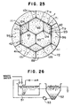
- A former apparatus for treating organic waste water has, as shown in Fig.26, a
reaction tank 51 to bring floating active sludge germ (a flock of various microorganisms) into contact with waste water. Thereaction tank 51 is connected with a settlingpond 52 and the waste water contacted with active sludge germ is separated by gravity in thesettling pond 52. The active sludge germs precipitate and the supernatant water is to be a treated water. - The
settling pond 52 is connected with thereaction tank 51 through asludge return pump 53. A precipitated active sludge germ is sucked by thepump 53 and returned as a second seed germ into thereaction tank 51. - The operation according to the apparatus is done continuously, and parts of active sludge germs do not precipitate in the settling pond but float in the supernatant water and flow out with the treated water.
- The more active sludge germs increase in number in the reaction tank, the speedier waste water is purified. However, as stated above, parts of active sludges flow out the settling pond so that the quantity of active sludge germs in the reaction tank is limited. Further, active sludge germs are not aggregates of only microorganisms which oxidise and resolve organic matters in the waste water, and generally they contain inactive microorganisms which do not directly take part in purifying.
- It is, therefore, an object of the present invention to provide an apparatus of less running cost.
- Another object of the present invention is to provide an apparatus of high efficiency for purifying waste water.
- Further object of the present invention is to provide an apparatus which can be assembled in a suitable scale under its using condition.
- According to the present invention there is provided apparatus for the treatment of organic waste water using micro-organisms, which apparatus comprises: an outer casing; partition means within the outer casing, which partition means are adapted to define an inner aerating portion and an outer return portion intermediate said outer casing, said inner aerating portion extending upwardly in use between open upper and lower ends thereof, which open upper and lower ends communicate with the outer return portion to define a circuit for waste water to circulate continuously between said inner and outer portions; a stack of vertically spaced, porous carrier discs disposed within said inner aerating portion, each disc having liquid passages formed therein and constituting a carrier for micro-organisms; one or more outlet ports in the outer casing, which outlet port(s) are disposed above the upper end of the inner aerating portion for the removal of treated waste water; a waste water supply tank for supplying waste water into said outer casing through a pipe, which waste water tank is adapted to be disposed at an elevated position relative to the outer casing to provide a head of waste water, a waste pipe for continuously supplying waste water to said tank, and an overflow mechanism to maintain a substantially constant level of waste water in the supply tank; and an air supply pipe connected to an air scattering disc disposed inside the outer casing below the lower end of said inner aerating portion.
- Said portion means may comprise an inner casing.
- Preferably, the outflow holes are made radially, each inner end face being open to an overflow groove provided along the inner periphery of the outer casing, the overflow groove being formed, by fixing an outer flange at the lower end of a circular board through which orifices pass radially to the inner periphery of the outer casing, the outer end face of the outflow hole being open to a circular gutter, and the circular gutter being provided on the outer circumference of the outer casing and connected with an outflow pipe. By deciding the height from the outflowing plane of the inner casing to the orifices, it can vary the circulating volume of the waste water to be treated, therefore, the more frequency of circulation are set, the more highly purified treated waste water can be taken out.
- Preferably, the circular board also functions as a guide pipe to lead part of the treated water upward and to overflow it through the orifices. As it prevents foams and the waste water from rising perpendicularly, the air stays long, and therefore, the oxygen dissolved therein increases and acts effectively on existence of microorganisms, and also the waste water snakes and increases a chance of contacting waste water with microorganisms.
- Preferably, the liquid passages comprise small holes provided all over the surface and large holes which stud the surface of the carrier disc, phases of the mutual large holes of the two carrier discs adjacent upward and downward being shifted with each other in the horizontal plane so that the mutual large holes do not align in a vertical line. As part of the waste water rises with less resistance through the large holes, it is useful for purifying the waste water, by increasing the number of its circulating times, and in the small holes it can effectively supply microorganisms with the oxide melted therein.
- Preferably, the liquid passage is the shape of cone cut off its head, a bore of the liquid passage in the waste water inflow side being smaller than that of outflow side. The frictional resistance of the waste water included foams in reduced and airlock can be checked.
- Also preferably, on the under plane of the carrier disc barriers are provided. The rising flow of the water mixed with the foams becomes equalized and the air stays long. The foams are prevented from gathering with each other or from becoming one body.
- Preferably, in use, the carrier discs are washed by rising foams and water and prevented from stacking thereto inert organisms, such as, algae, mold, etc., so that micro pores in the carrier discs are not clogged. The carrier discs are washed by rising foams and water and prevented from stacking thereto inert organisms, such as, algae, mold, etc., so that micro pores in the carrier discs are not clogged, life environment of microorganisms is kept comfortably and the carrier disc can be used long.
- Alternatively, said partition means may comprise a plurality of partition walls, each partition wall being interposed an adjacent pair of carrier discs to seal the space therebetween such that said plurality of partition walls substantially form an inner casing.
- Preferably, the outflow holes are open at their inner end to an overflow groove provided along the inner periphery of the outer casing. The overflow groove is formed, by fixing an outer flange at the lower end of a circular board through which orifices pass radially to the inner periphery of the outer casing. The outer end face of the outflow hole is open to a circular gutter, and the gutter is provided on the outer circumference of the outer casing and connected with an outflow pipe. The overflowed water can be flowed directly to the outflow pipe through the outflow port.
- Said outer casing may be closed at its upper end by a plate and has exhaust ports at level above said outflow port. As the upper end of the outer casing is closed by the top plate and has the exhaust ports at its upper portion, rainwater, snowfall and dust do not enter and it can keep the capacity of treating waste water from lowering.
- Further, preferably, such structures are adopted which the liquid passages are made as small and large holes and the mutual large holes of the two carrier discs adjacent upward and downward are shifted so as not align in a vertical line and which a bore of the liquid passage in the waste water inflow side is made smaller than that of outflow side.
- Said outflow path may accommodate a stack of porous outer carrier discs that constitute a carrier for microorganisms and means for spacing each outer carrier disc from its neighbouring discs. As it is piled in order the inner or the outer carrier discs and the inner partition walls, an apparatus of a large scale is made easily. And it can be raised the degree of purifying the circulating waste water as it falls under the preying function of the microorganism at both the inner and the outer carrier discs.
- Preferably, each of the outer carrier discs is made by connecting units in a ring-like form, each of the units being the shape which corresponds to a segment formed by a side of the inner carrier disc, radiations from the center of the inner carrier disc to both ends of the side and a side of the outer casing cut off by the radiations. By connecting the outer carrier discs in a ring-like form in a horizontal plane, they are closely fit in the downward circuit around the outer circumference for flowing down the waste water.
- Preferably, the inner carrier discs and the units and the mutual units are connected, by fitting each in respective grooves of an H-shaped rail. Respective connecting portion closely contacts with each other and the connection is easily done.
- Preferably, each outer carrier disc is made by connecting units in a ring-like form. Each unit is the shape which corresponds to a segment formed by a side of the inner carrier disc, radiations from the center of the inner carrier disc to both ends of the side and a side of the outer casing cut off by the radiations.
- Further, preferably, the mutual regular hexagonal carrier discs, the regular hexagonal carrier disc and the rhombic segment, the regular hexagonal carrier disc and the unit, the rhombic segment and the unit and the mutual units are connected, respectively, by fitting each in respective grooves of an H-shaped rail. As the regular hexagonal inner carrier disc is formed rhombic segments in the shape of trisection of the regular hexagonal segment in the same plane, when choosing number of them and forming a regular hexagon, it can freely be formed the inner carrier discs of from small to large sizes.
- The inner sizes of the inner and outer casings are determined according to quantity and quality of waste water to be treated. These inner and outer casings are preferably cylinder, but one or both of them may take the form of a polygon, and when the outer casing takes the form of fixing the bottom cap to its lower portion, it becomes easy to set the inner casing in the outer casing.
- Carrier discs of polyethylene to which microorganisms are made to take root and which have liquid passages are prepared. The material is the same as adopted in the patent publication No.8-10557 filed by the present applicant. The material is made of a high density polyethylene and is placed on sale under the article name [POLEX] (the trade mark of TECHNOLOGIES CO., LTD.)
- The number of the carrier discs is determined according to a property of waste water and it is preferable to suit the outer shape of the carrier disc to the sectional shape of the inner casing.
- The necessary numbers of the carrier discs are piled with each space between every two carrier discs in the inner casing. This piling is easy when done as follows.
- Let the necessary number of the carrier discs align and let a spacer put in between every two carrier discs. And let bolts pass through bolt holes of each carrier disc and spacers in order for making a disc assembly.
- Supporters such as flanges, pins, etc., are formed on the inner periphery of the lower portion of the inner casing and let the disc assembly be supported by the supporters, by inserting the disc assembly into the inner casing through its uppermost opening plane.
- If it is hard to have disc assembly be supported directly on the supporters, let a screen be put on the supporters and let the disc assembly be supported onto the screen.
- It is preferable to make microorganisms take root to a carrier disc as it is, but they may be made to take root to a disc assembly form.
- The inner casing may be coaxially placed in the outer casing. The inner sizes of the inner and outer casings are determined so as to form a flow down circuit for liquid between both planes facing each other, that is, between sides and the upper and lower ends. The coaxial placement of both casings can be done, for example, by protruding pins from the inner wall of the outer casing to its canter. Also, the setting of the inner casing in relation to the outer casing in the axial direction can be done, by providing ledges for receiving the inner casing on or by protruding arms from the inside of the outer casing. At all events, by this, the waste water flown into the bottom portion of the outer casing rises into the inner casing through its lower opening. The waste water overflows, by supplying air therein, at its upper end and flows down in the flow down circuit to the bottom portion of the outer casing, and then the waste water is to repeat a travel entering again the inner casing through its lower opening and rising.
- The outer casing has an outflow ports for the treated water, which are open at the upper portion than the overflow plane at the upper end of the inner casing.
- "Which is open" described above includes in cases of the outflow ports being directly open and being led by means of other passage.
- By varying the difference between the level of the outflow ports and the overflow plane, degree of contact for treating waste water, that is, the volume of circulation can be varied.
- There are three ways of doing the variation.
- (1) Let a head of waste water to be fed in the outer casing vary.
- (2) Let volume of air to be supplied in the inner casing through the air supply pipe adjust.
- (3) Let a level of an overflow hole of the inner casing vary upward or downward.
-
- The adjustment is preferable to be adjustable type when quality and quantity of waste water to be treated, but it may be fixed type when invariable.
- In a ward, the ratio between quantities of liquids flowing out through the outflow port at the uppermost and circulating between the inner and the outer casings is to be number of turn.
- This ratio is easily settled at high so that efficiency rises, and even an apparatus of small size can effectively be applied.
- The waste water supply tank is for having waste water a head to flow into the outer casing. Above the tank a waste water supply pipe is open to continuously supply waste water therein and an excess waste water is drained outward at the overflow. The supplying may be done by natural flowing down or by pumping up from a waste water sink.
- When let the overflow open to a sink, waste water can be utilised cyclically. The inside of the waste water tank communicates with the bottom of the outer casing by a leading pipe, and when let a valve on the way open, the waste water given a head flows out of the waste water supplying tank into the outer and the inner casings through the leading pipe.
- And, the air supply pipe is connected at one end with an air supply source such as blower and at the other end with an air scattering disc below the lower end of the inner casing in the outer casing. The air scattering disc is an ordinary type which emits air supplied thereto from the face as foams.
- In use, air is fed through an air supply pipe. From the upside of the air scattering disc, numberless small foams rise and enter into the inner casing and rise through the liquid passages of the carrier discs. By this feeding in of foams, the water level in the inner casing rises, and waste water overflows at the open plane at the upper end of the inner casing.
- In numberless pores in each carrier disc, numberless microorganisms are made to take root, and when waste water passes through the liquid passages organic substances contained therein are made a prey of the microorganisms. The waste water is purified gradually during its circulation between the inner and the outer casings, and the purified treated water is, by overflowing through the outflow ports, taken out of the outer casing.
- The outflow holes are made radially. The inner end planes of the outflow ports are open to an overflow groove provided along the inner periphery of the outer casing. The overflow groove is formed, by fixing an outer flange at the lower end of a circular board through which orifices pass through radially to the inner periphery of the outer casing.
- If the inner ends of the orifices are open above the overflowing plane of the inner casing, the inner ends of the outflow ports may be located under the overflowing plane of the inner casing.
- The outer end faces of the outflow holes are open to a circular gutter, which is provided on the outer circumference of the outer casing and connected with an outflow pipe.
- When made like this, by settling the height from the overflowing plane of the inner casing to the orifice, quantity of circulation for treating waste water can be varied.
- In case the liquid passages comprise small holes provided all over the surface and large holes which stud the surface of the carrier disc, phase of the mutual large holes of the two carrier disc adjacent upward and downward being shifted with each other in the horizontal plane so that the mutual large holes do not: align in a vertical line, part of waste water rises with less resistance and the number of circulation of waste water increases, so that it is useful for purifying the waste water and the oxygen melted therein is effectively supplied to microorganisms in the small holes. Also the air stays long, therefore, the oxygen melted therein increases and acts effectively on microorganisms for their living, and let waste water snake to increase a chance of contacting waste water with microorganisms.
- In case, the liquid passage is the shape of a cone cut off its head, a bore of the liquid passage in the waste water inflow side being smaller than that of outflow side, the frictional resistance to the water including foams becomes less also air locking can be prevented.
- In case, on the under plane of the carrier disc barriers are provided, the rising flow of the water including foams becomes equalised and the time for keeping air is elongated.
- In case, the carrier discs are washed by rising foams and water and prevented from stacking thereto inert organisms, such as, algae, mold, etc., so that micro pores in the carrier discs are not clogged, life environment of microorganisms is kept comfortably and the carrier disc can be used long.
- Where outer carrier discs are provided, a liquid passage is provided for preventing waste water from naturally flowing down by the outer carrier discs and for multiplying a chance of contacting organic substance with waste water.
- The inner partition walls are arranged respectively along the outer periphery of each regular hexagonal inner carrier disc assembly closely in each space between every two inner carrier disc assemblies. The "outer periphery" here stated includes in case of the outer periphery of a plane of the carrier disc and of an outer portion of a plane of the outer carrier disc which is connected with a carrier disc. Also being "arranged closely in each space" means to form by the inner partition wall an enclosed space between two inner discs adjacent upward and downward direction.
- Accordingly, when keeping on piling carrier discs in order and inserting the inner partition wall in each space, finally the inner partition walls forms substantially a cylinder. It executes substantially the same function as of the inner casing of the first apparatus.
- The outer casing may be coaxially arranged with the inner casing with a downward circuit for liquid between them. As the inner partition wall is arranged along the outer periphery of the regular hexagonal inner carrier disc, the outer casing is also to be arranged coaxially with carrier disc. The outer casing is closed of its bottom by a bottom cap and of its top by a top plate. The outer casing has an outflow port for the treated water above the uppermost inner carrier disc and exhaust ports above the outflow port.
- Where the upper end of the outer casing is made of an open type, the exhaust ports are not needed, but where there is the top plate, the exhaust ports are provided. If not the exhaust ports, in case the apparatus is settled outdoors, rain or snow mixes with waste water and environment around microorganisms varies and microorganisms die or become lost their activities. Therefore, the expected treatment of waste water can not become done.
- In the circuit between the outer casing and the inner partition wall porous outer carrier discs of polyethylene for taking microorganisms root thereto are closely piled with a space between every two discs.
- Where outer carrier discs are provided organic waste water to be treated circulates in use at high speed upward at the central aerating portion of the apparatus and downward in the downward circuit in the outer circumference. The regular hexagonal carrier discs and the outer carrier discs (porex sheets) taken root with active sludge organisms are arranged with a space between two discs in the aerating portion enclosed by the inner partition wall which forms substantially the inner casing and in the downward circuit where waste water flows down, respectively, and during the frequent contact with the circulating water at each step, the organic substances in the waste water are taken out.
- Quantity and treating speed of organic matter to be treatable are proportioned to the absolute volume of the fixing organisms which live within both the carrier discs, so that the more capacities of both the carrier discs the better, but from a structure of apparatus and an economical efficiency a rational capacity is required naturally.
- In particular an aerating portion is, on various elements such as a height of a pile, sectional area, a shape, of the inner carrier disc, demanded a rational size to be obtainable a necessary and enough supply of air and the rising of water level necessary for circulating at high speed. Accordingly, to increase capacity a necessary capacity is to be kept in the downward circuit in the outer circumference, and in this case, also a rational sectional area and capacity which can be obtained an even flow and can apply effectively whole outer carrier discs piled must be required.
- As in the central aerating portion (the inner casing) the circulating water and air from aeration mix and rise coming into contact with the inner carrier discs, a time for substantially contacting the inner carrier discs with waste water shorten relatively.
- When the waste water flows into the outer circumferential portion the foams are separated therefrom, and only the waste water flows down, coming into slow contact with the outer carrier discs, in the downward circuit in the outer circumference.
- When compared of the contacting times of the waste water with the inner carrier discs and with the outer carrier discs, it becomes about 20 in the downward circuit to in the aerating portion.
- Also when compared the substantial capacities of the inner carrier discs with that of the outer carrier discs, it is preferable that the downward circuit has about 1.35 times to the aerating portion.
- When considered the comparison of the numerical value stated above, the greater part of treating function in the second apparatus is to be in the downward circuit in the outer circumstances. The inner carrier discs piled in the central aerating portion have the functions for raising melting speed of oxygen in the air in the circulating water and the water level to obtain a circulation at high speed, so that they have, in the structure of the apparatus for treating waste water, they have a necessary indispensable meaning.
- It is not possible to achieve such a treatment at high speed until the central aerating portion and the downward circuit of the outer circumference act together.
- Where, the outflow port is open at its inner end to an overflow groove provided along the inner periphery of the outer casing, the overflow groove being formed, by fixing an outer flange at the lower end of a circular board through which orifices pass radially to the inner periphery of the outer casing, the outer end face of the outflow port being open to a circular gutter.
- When made like this, by adjusting the height from the overflowing plane of the inner case to the orifice, the circulating quantity to be treated can be varied and the treated waste water can be drained directly to the outflow pipe through the outflow ports.
- When each of the outer carrier discs is made by connecting units in a ring-like form, each of which is the shape corresponding to a segment formed by a side of the regular hexagonal inner carrier disc, radiations from the center of the inner carrier disc to both ends of the side and a side of the outer casing cut off by the radiations, it becomes easy to coaxially arrange the central aerating portion with the outer circumferential downward circuit for flowing the waste water downward. The unit is to be the shape of a fan when the outer casing is cylinder, and a trapezoid when a similar figure as the inner carrier disc.
- When the regular hexagonal inner carrier discs and the and the mutual units are connected, by fitting each in respective grooves of an H-shaped rail, respective connecting portions are closely contacted and also it becomes easy to connect them.
- The inner carrier discs may be an assembly, which comprises regular hexagonal discs and rhombic segments in the shape of a trisection of the regular hexagonal disc and is made by arranging the regular hexagonal disc in the center in a honeycomb fashion and the rhombic segments in the empty portions in the outer circumference.
- There are cases one or two or more outer carrier disc(s) is(are) applied to a side of the carrier disc assembly.
- This case is applicable for enlarging an apparatus.
- Following is a description by way of example only with reference to the accompanying drawings of embodiments of the present invention.
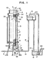
- Fig.1 is a partially cut off side view which illustrates one embodiment of the apparatus for treating waste water utilising microorganisms of the present invention.
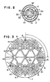
- Fig.2 is a plan view of a parts of the inner and the
outer casings - Fig.3 is the base view of the
carrier disc 7 for making microorganisms take root therein. - Fig.4 is a partially enlarged view of Fig.3 showing the
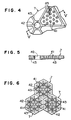
small holes 43 in limited area. - Fig.5 is a section along line 5-5 of Fig.4.
- Fig.6 is an explanatory view of the honeycomb like carrier disc when in use.
- Fig.7 is a partially cut off side view which illustrates another embodiment of the present invention.
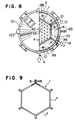
- Fig.8 is a partially cut off plan view of Fig.7.
- Fig.9 is a plan view showing the detail of the inner partition wall 1' which is partially cut off.
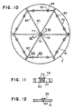
- Fig.10 is a plan view of the receiving
frame 73. - Fig.11 is a section along line 11-11 of Fig.10.
- Fig.12 is a section along line 12-12 of Fig.10.
- Fig.13 is a detail of the supporting structure of the receiving
frame 73 to theouter casing 2. - Fig.14 is a plan view of the restrainer 74.
- Fig.15 is a side view of the Fig.14.
- Fig.16 is a side view of the spacer 75 a half of which in section.
- Fig.17 is a plan view of Fig.16.
- Fig.18 is a side view of the spacer 76 a half of which in section.
- Fig.19 is a plan view of Fig.18.
- Fig.20 is an end view of the H-shaped rail.
- Fig.21 is a plan view of the corner spacer 111.
- Fig.22 is a side view of Fig.21.
- Fig.23 is a plan view of the
corner spacer 124. - Fig.24 is a plan view of the
corner spacer 125. - Fig.25 is a plan view illustrates an assembly of inner carrier discs used in yet another embodiment of the present invention.
- Fig.26 is a rough drawing of an apparatus for treating organic waste water heretofore in use.
- In the following explanations, through the whole figures the same numeral designate the same or corresponding portion.
- Fig.1 through Fig.6 show a first embodiment of the present invention.
- A first apparatus comprises an
inner casing 1, anouter casing 2, a wastewater supply tank 3 and anair supply pipe 4. Theinner casing 1 is a vertical cylinder and its upper and lower ends are open. Theinner casing 1 is provided with adisc assembly 5 therein. Thedisc assembly 5 is such that carrier discs to which microorganisms are made to take root of porous and having liquid passages 6 are piled by means ofbolts 10 which pass through theirbolt holes 8 andspacers 9 inserted between every two carrier discs and nuts 11. - The
carrier disc 7 shown in the drawings is a form of a circular disc. The carrier disc is made of an intensified polyethylene and the material is placed on sale under the article name [POREX] (a trade mark of TECHNOLOGIES CO., LTD.) - The
outer casing 2 is a vertical cylinder and its bottom is closed by abottom cap 12. Theouter casing 2 is arranged coaxially with theinner casing 1 with adownward circuit 13 between them. Theouter casing 2 hasoutflow ports 14 for the treated water above the opening plane serving the purpose of an overflow at the upper end of theinner casing 1. - The waste
water supply tank 3 is for having waste water a certain head and settled on an appropriate outside position of theouter casing 2. Above the tank 3 a wastewater supply pipe 15 is open and waste water is supplied continuously therein. The other end of the wastewater supply pipe 15 may be connected with a passage of waste water or, as shown in the drawings, with awaste water sink 16 through apump 17. Waste water is to be fed to thesink 16. - The inside of the waste
water supply tank 3 leads to the inside of theouter casing 2 through thebottom cap 12 by means of a leadingpipe 19 with avalve 18. The wastewater supply tank 3 is provided with anoverflow 20 and adrain pipe 21 is made to open to thewaste water sink 16. - Waste water is supplied continuously in the
waste water tank 3 through the wastewater supply pipe 15 and an excess waste water is drained outward at theoverflow 20. When let avalve 18 open, the waste water given a head flows out of the wastewater supply tank 3 into theouter casing 2 and theinner casing 1 through the leadingpipe 19. - The
air supply pipe 4 is at one end connected with anair scattering disc 22 located under the lower end opening plane of theinner casing 1 in theouter casing 2 and at the other end connected, as usual, with an air supplying machine such as a blower (not shown). - The
air scattering disc 22 is an ordinal type which placed on sale. - In using the apparatus let microorganisms take root to the
carrier discs 7. To take root is preferably done when the carrier disc is in itself but it may be done when the carrier discs are in a state of a disc assembly. - When the
valve 18 opens waste water flows by its head into theouter casing 2, theinner casing 1 and thedownward circuit 13. - At this point, air is fed, by starting a blower and the like, to the
air scattering disc 22 through theair supply pipe 4. The air becomes small foams as usual when it passes through theair scattering disc 22 and rises evenly in theinner casing 1. - As the volume of foams increases, the level of the waste water in the
inner casing 1 rises, and the waste water overflows at the opening plane at the upper end of the inner casing and flows in thedownward circuit 13 between the side walls of theouter casing 2 and theinner casing 1. - The foams are at this moment separated from the waste water and discharged in atmosphere through the opening plane at the upper end of the
outer casing 2. The waste water overflowed in thedownward circuit 13 between the side walls of theouter casing 2 and the inner casing flows down thedownward circuit 13 and again rises with foams in theinner casing 1. Thus the waste water repeats the stroke. - The waste water contacts, when it passes through the liquid passages 6 of the
carrier disc 7, with the microorganisms taken root therein and the organic matters contained in the waste water are made a prey of the microorganisms and the waste water is gradually purified. - The number of circulating times of waste water is suitably decided as waste water is purified. The decision is done, by performing one work or two or more assembled works such as settling a head of the waste water supplied from the waste
water supply tank 3, adjusting a volume of air from theair supply pipe 4, varying the height of the orifice 31' of theouter casing 2. - With respect to quality of the waste water, it can cope by adjusting the number of the
carrier discs 7 or by arranging the treating apparatuses in series and also with respect to quantity of waste water it can cope by planning the capacities of theouter casing 2 and theinner casing 1 for fitting thereto or by arranging the treating apparatuses in parallel. - During the operation of the treating apparatus, part of the purified waste water flows continuously through the
outflow ports 14 out of theouter casing 2 and proportionate quantity of waste water to the flown out quantity flows continuously in theouter casing 1 from the wastewater supply tank 3. - The
outflow ports 14 are made radially. Each inner end plane of theoutflow ports 14 is open to anoverflow groove 31 which is provided along the inner periphery of theouter casing 2. Theoverflow Groove 31 is formed, by fixing anouter flange 33 at the lower end of acircular board 32 through which orifices 31' pass radially to the inner periphery of theouter casing 2. The outer end planes of theoutflow ports 14 are open to acircular gutter 34, which is provided on the outer circumference of theouter casing 2 and connected with anoutflow pipe 35. - When made like this, it can be decided, by adjusting the height between the opening plane at the upper end of the
inner casing 1, that is, an overflow plane of the waste water and the orifices 31' of theoverflow groove 31, quantity of circulating waste water. - Phases of the mutual liquid passages 6 of two
carrier discs 7 adjacent upward and downward are shifted with each other in the horizontal plane so that the mutual liquid passages 6 do not align in a vertical line, that is, in case the liquid passages 6 of thecarrier discs 7 are located as shown in Fig.3, when one of thecarrier discs 7 is rotated in a 90-degree to the arrow, the liquid passages 6 of one of thecarrier discs 7 are so shifted within an area against the other carrier disc as not to pass through with each other in a vertical line. Thus, the air stays long, therefore, oxygen melted therein increases and acts effectively on microorganisms for their living, and by letting the waste water snake, a chance of contacting the waste water with microorganisms increases. - The liquid passages 6 comprise
small holes 41 provided all over the surface andlarge holes 42 which stud the surface of thecarrier disc 7. - When made like this, part of the waste water rises through the
large holes 42 with less resistance and the number of circulations of the waste water increases, so that it is useful for purifying the waste water, and in thesmall holes 41 oxygen melted therein and energy source are effectively supplied to the microorganisms taken root therein. - Each liquid passage 6 is, as shown in Fig.5, the shape of a cone cut off its head, a bore of the liquid passage in the waste water inflow side being smaller than that of outflow side, the frictional resistance to the water including foams becomes less and also air locking can be prevented.
- On the under plane of the
carrier disc 7barriers 43 are provided. By this, it becomes equalise the rising flow of the water including foams and the time for keeping air is elongated. - The
carrier disc 7, as shown in Fig.6, is the regular hexagonal shape which is connectable in a honeycomb fashion. Therefore it can cope with the variation of quantity of waste water to be treated, by connecting thecarrier discs 7 and securing a necessary area. - The
carrier discs 7 are washed by the rising foams and water and prevented from stacking thereto inert organisms, such as, algae, mold, etc. Accordingly, as micro pores in thecarrier discs 7 own are not clogged, life environment of microorganisms is kept comfortably and it can be used long the carrier discs. - And, in the drawing, bars 61 are fixed on the top of the
outer casing 2 and spanned over theoverflow groove 31.Arms 62 protruding radially from the outer periphery at the upper end of theinner casing 1 are for cantering theinner casing 1. - A
base 63 is for supporting carrier discs.Legs 64 are provided at lower end of theinner casing 1. Adrain 65 and a wastewater inflow pipe 66 are shown in Fig.1. - Fig.7 through Fig.9 show a second embodiment of the present invention.
- Here described are mainly on the different points from the first apparatus.
- The
inner carrier discs 71 are the regular hexagonal shapes and piled in the same phases with each space between every two discs, and around the outer circumferences of theinner carrier discs 71 theouter carrier discs 72 are piled with each space between every two discs. - The inner partition wall 1' is arranged between the
outer carrier discs - The inner partition wall 1' may be formed in advance of a regular hexagonal cylinder having an axial length fitting in with a space between the
outer carrier discs - Also, when the inner partition wall 1' is, as shown in Fig.9, formed in order by connecting six
segments 1" each of which is a board of length fitting for a side of the regular hexagon and formed outward ears at its both ends with each bolt hole through them, by means of bolts and nuts, it is easily fitted in an apparatus of a large scale. - The inner partition wall 1' is in the middle of an assembly in a state merely put between the
outer carrier discs - When let
bolts 10 pass through the uppermost outer carrier disc 72' and thelowermost carrier disc 72" and letnuts 11 fasten, the inner partition wall 1' fastens closely on the upper and thelower carrier discs 72 and closes the inner space S. Thus, the inner partition walls 1', putting theouter carrier disc 72, forms an apparent inner casing as of the first apparatus;, and the waste water which rises on aerating function naturally passes through theinner carrier discs 71. - One embodiment of a method to assemble the inner and the
outer carrier discs - In case of the
inner carrier disc 71, receivingframes 73 of regular hexagons (Figs.10-13), restrainers 74 (Figs.14, 15),spacers 75, 76 (Figs.16-19) andbolts 10 andnuts 11 as of the first apparatus are used. Each receivingframe 73 has aboss 77 at its center, which is provided on the upper plane with areceiver 78 for aspacer 75. - Through the boss 77 a
hole 79 for thebolt 10 passes. From theboss 77 sixarms 80 protrude radially at an even angle and each end of thearms 80 are connected withledges 81. - Each
arm 80 is longer than the size from the center of theinner carrier disc 71 to one of its apexes and holes 82 forbolts 10 are made just outward of the apexes. Eachledge 81 is for supporting theouter carrier disc 72 and provided on its upper plane withsaucers 83, and in their axial lines holes 84 for thebolts 10 pass through theledges 81. - Each restrainer 74 has a
hole 86 passing through theircentral boss 85 for thebolt 10 and from theboss 85 sixarms 87 protrude radially at an even angle, and the outer end of eacharm 87 comes near to the corner of theinner carrier disc 71. - Figs.16 and 17 show the
spacer 75. Thespacer 75 is for receiving theinner carrier disc 71 of wide area and thespacer 76 is for a unit (Fig.8) of lesser area to form theouter carrier disc 72. It is a mountain like in section, through which anaxial hole 89 for thebolt 10 passes and thebase plate 92 protrudes upward in a size fitting to a thickness of theinner carrier disc 71 and is for fitting closely in a hole 93 (refer also to Fig.8) of theinner carrier disc 71. A protruding portion from the upper end of the mountain likeportion 92 becomes areductive diameter portion 94 and at the lower end of the axial hole 89 alarger diameter portion 95 of a length in which thereductive diameter portion 95 of anotherspacer 75 closely fits in is provided. - The
spacer 76 shown in Figs.18 and 19 is almost same structure as thespacer 75. Only, there is not arib 90 to thebase plate 91, the outer diameter of the base plate being small and the diameters of the mountain likeportion 92 and theaxial hole 89 also being shortened. - The
bolt 10 and thenut 11 are the same as used in the first apparatus. - Let the receiving
frame 73 put on a lifting cylinder (not shown) and getting thebase portion 91 of thespacer 75 into thereceiver 78 of theboss 77. Let theinner carrier disc 71 put thereon, coaxially with the receivingframe 73 and facing each corner to eacharm 80 of the receivingframe 73, and let the mountain likeportion 92 of thespacer 75 fit in thecentral hole 93. - Next, let the
larger diameter portion 95 of thebase portion 91 of thesame spacer 75 fit in thereductive diameter portion 94 of the mountain likeportion 92 of thespacer 75, and let thehole 93 of anotherinner carrier disc 71 of a like structure fit on the mountain likeportion 92 of thespacer 75. Thehole 93 can not pass through thebase portion 91 and theinner carrier disc 71 stops coming into contact with the upside of thebase portion 91, that is, the height of thebase portion 91 fix the height of the space S between twoinner carrier discs 71. - From here forth by doing like this, they are assembled in order. When it becomes the height which excesses the area of working, let the cylinder lower each time.
- When the uppermost inner carrier disc 71' has been set, let the restrainer 74 put thereon and then let the
hole 86 align with theaxial hole 89 of thespacer 75. By letting thebolt 10 pass there through and letting the nuts 11 fasten at its both ends, a disc assembly 5 (Fig.7) is formed. Theinner carrier discs 71 are not flapped by buoyancy. It may be assembled by letting thebolts 10 stand in advance on a cylinder and the inner carrier discs pass through the bolts. It is similar in case of theouter carrier discs 72 and also it is applied in the following case. - Next, in case of the
outer carrier disc 72, the receivingframe 73 is used together with theinner carrier disc 71. Also at suitable position of theouter carrier disc 72 holes 96 (refer also to Fig.8) for thebolts 10 are made. - Assembling is similarly done as the
inner carrier discs 71 through thespacers 76. In case of theouter carrier discs 72, as buoyancy by air does not act, the restrainer 74 is not needed. Theouter carrier discs 72 are restrained directly by means of the nuts 11 at both ends of the bolts. - Fig.20 shows an H-shaped
rail 101. Therail 101 is used for connecting theouter carrier discs 72 along the outer circumference of in the same plane with theinner carrier disc 71. In eachgroove 102 of both sides of the rail, theinner carrier disc 71 and the outer carrier disc 72 (when theouter carrier disc 72 is formed withunits 88, mutual respective unit 88) fit therein. When the H-shaped rail is formed with a male andfemale members webs 103 which are adjustable of their lengths, it can carry out close contact of both carrier discs with therail 101 when they fitted in eachgroove 102, respectively. - Figs.21 and 22 show a corner spacer 111 which is applied to a corner of the
inner carrier disc 71. The corner spacer 111 is provided with aspacing portion 112, aprotrusion 113 on the underside of the portion, aprotrusion receiver 114 aligned with theprotrusion 113 and protruding from the upper plane of theportion 112, and a couple ofrail receivers 115 spread Ed from the axial line of theprotrusion 113 at right angle with a 120 degree between them. - From the
protrusion 113 to the protrusion receiver 114 ahole 116 for thebolt 10 passes through. - When the
protrusion 113 of one of the corner spacer 111 fitted in theprotrusion receiver 114 of another corner spacer, an end of therail 101 is held between the facingrail receivers spacing portion 112 it can be kept of a fixed space between theouter carrier discs inner carrier discs - In the state,
respective carrier discs bolts 10 pass through the corner spacers 111 which continue with each other and they are fixed by the nuts 11. - The lowermost
outer carrier disc 72" is connected outward with the lowermostinner carrier disc 71" by means of the H-shapedrail 101 and put on the receivingframe 73. When theouter carrier disc 72 is formed with theunits 88, themutual units 88 are also connected with each other by means of the H-shapedrail 101 and encircle the outer circumference of theinner carrier disc 71. Along the outer circumference of the H-shapedrail 101 which connects theinner carrier disc 71 with theouter carrier disc 72, the inner partition wall 1' is surrounded. - Here, again another outer carrier disc put through the
spacer 76 thereupon and the inner partition wall 1' is surrounded. Hereinafter assembled like this, let thebolt 10 pass through the uppermost outer carrier disc 72' and the lowermostouter carrier disc 72" and let them fasten with nuts 11. - The
outer casing 2 is a cylinder and coaxially arranged with the inner partition wall 1', and thedownward circuit 13 for flowing the circulating waste water downward is formed between them. The bottom of theouter casing 2 is closed by thebottom cap 12 and the top is closed by thetop plate 121. And theouter casing 2 is, above the uppermost inner carrier disc 71', provided with theoutflow port 14 for the treated water and theexhaust ports 122 above theoutflow port 14. - The
outer carrier discs 72 are piled in thedownward circuit 13 with a space between every two outer carrier discs and theouter casing 2 is in close contact with each of them. Theouter carrier disc 72 may be formed by connecting in ring-shaped theunits 88. Theunit 88 in the form of a fan when theouter casing 2 is a cylinder and a trapezoid when a similar figure. - The
inner casing 1 used in case of the first apparatus is not used in the second apparatus and the inner partition walls 1' connected through the outer carrier disc upward and downward forms theinner casing 1 in appearance to act its function. Also thecircular gutter 34 is omitted, by connecting theoutflow port 14 directly with theoutflow pipe 35. - In case of the second apparatus, the waste water rises with the air in the
inner casing 1 in appearance formed with the inner partition walls 1' piled through theouter carrier discs 72. The organic substances included therein contact with the microorganisms in theinner carrier discs 71 and become the prey of them and the waste water overflows at the upper end of theinner casing 1. - The waste water in the
inner casing 1 increases its capacity by the numberless foams fed therein so that part of it rises in a space enclosed by thecircular board 32 and flows out in theoverflow groove 31 through the orifices 31' and then it flows out directly in theoutflow pipe 35 through theoutflow port 14. Also the foams are separated in the space from the waste water and exhausted through theexhaust ports 122. - The great part of the waste water which overflowed at the end of the inner casing and lost the foams included therein flows in and down naturally the downward circuit around the outer circumference. Flowing down through the
outer carrier discs 72, the waste water comes in contact with the microorganisms taken root therein and the organic substances in it become the prey of them. Accordingly, it rises the purifying degree of waste water per one circulation. - The passing speeds through the inner and the
outer carrier discs <Inner carrier disc> Sectional area in appearance 0.4935m2 Sectional area for passing the circulating water there through 0.1029m2 Open area rate (0.1029/0.4935)x100=20.85%
Q=69.41/min (100m3/d)Quantity of air 1000l/min Passing speed V0(69.4+1000)x10-3x1/0.4935 =0.036 1m/s
V1(69.4+1000)x10-3x1/0.1029 =0.173m/s<Outer carrier disc> Sectional area in appearance 0.6684m2 (OUT/IN=1.35) Sectional area for passing the circulating water there through 0.1334m2(OUT/IN=1.30) Open area rate (0.1334/0.6684)x100=19.96% (OUT/IN=1.30)
Q=69.41/min (100m3/d)Quantity of air 1000l/min Passing speed V0 69.4x10-3x1/60x1/0.6684 =0.000173m/s (OUT/IN=0.05)
V1 69.4x10-3x1/60x1/0.1334 =0.00867m/s(OUT/IN=0.05) - The
outflow port 14 is at its inner end open to theoverflow groove 31 around the inner periphery of theouter casing 2. Theoverflow groove 31 is formed, by fixing theoutward flange 33 at the lower end of thecircular board 32 through which the orifices 31' pass through radially to the inner periphery of theouter casing 2. When made like this, by adjusting the heights between the opening plane, that is, the overflowing plane for the waste water, at the upper end of theinner casing 1 and the orifices 1' of theoverflow groove 31, it can be settled quantity of waste water to be circulated. - Fig.25 is a plan view of the parts of the inner and the
outer carrier discs - The
inner carrier disc 71 becomes an assembled carrier disc. Theinner disc 71 comprises three regularhexagonal discs 71a and three rhombic segments 71b in the shape of trisection of the regular hexagon. Theinner carrier disc 71 is made by arranging the regularhexagonal disc 71a in the center in a honeycomb fashion and the rhombic segments 71b in theempty portions 123 in the outer circumference. The outer carrier discs are, though omitted in the drawing, arranged coaxially with and forming adownward circuit 13 for liquid between them. And, in the downward circuit the pluralouter carrier discs 72 are piled with a space between every two outer carrier discs. - In this case, when it is assembled in order the regular
hexagonal discs 71a and the rhombic segments 71b, a large assembly of the carrier disc can be obtained so that it can easily be formed an apparatus of large scale. - The process of treating waste water is the same as in the second apparatus.
- To connect the regular
hexagonal disc 71a with the rhombic segment 71b which forms a carrier disc assembly in this case, the H-shapedrail 101 in the second apparatus and corner spacers 124 (Fig.23) which is a modification of the corner spacer 111 and hasrail receivers 115 spread with 60-degree between them. - Also, at the connecting portion of an out side of the regular
hexagonal disc 71a with the rhombic segment 71b, a corner spacer 125 (Fig.24) is adopted, which has therail receivers 115 which spread at right angle with the axial line with a 180-degree and which has arail receiver 115 which in both the rail receivers spreads with a 60-degree to one of the receivers. - The corner spacer arranged at the outer corner of the rhombic segment 71b is the same as the corner spacer 111 of the second apparatus.
- The piling of the
outer carrier discs 72 is the same as the second apparatus, and in case of its size being too large, it may be formed as aunit 88 and further, theunit 88 may be formed by connecting divided parts in two or more with each other. - The process of treating waste water is done like as in the second apparatus.
- According to the present invention, as microorganisms are made to take root in the porous carrier discs, which are piled in the inner casing with each space between every two carrier discs, it becomes sufficient the contacting efficiency of microorganisms with waste water.
- Also, as the inner casing being arranged in the outer casing coaxially with it, the downward circuit for the waste water to be treated is formed between them and under the lower end of the inner casing an air scattering disc for sending out air as small foams is provided, waste water to be treated rises by the foams in the inner casing and overflows at the opening plane at its upper end in the downward circuit between them to the bottom portion of the outer casing. The waste water flows again in the inner casing and rises by the foams. Thus, the circuit of the waste water is formed and during its circulation organic matters in the waste water becomes the prey of the microorganisms taken root to the carrier discs in the inner casing.
- As the outer casing has the outflow holes which are open to the upper portion than the overflowing plane of the inner casing, it can overflow outward part of the circulating waste water through the outflow holes so that even the apparatus of small size can effectively treat waste water.
- When arranging the treating apparatus in series, it can cope with quality of waste water and when in parallel it can cope with its quantity.
Claims (20)
- Apparatus for the treatment of organic waste water using micro-organisms, which apparatus comprises;an outer casing (2);partition means (1, 1') within the outer casing, which partition means are adapted to define an inner aerating portion and an outer return portion intermediate said outer casing, said inner aerating portion extending upwardly in use between open upper and lower ends thereof, which open upper and lower ends communicate with the outer return portion to define a circuit for waste water to circulate continuously between said inner and outer portions;a stack of vertically spaced, porous carrier discs (7, 71) disposed within said inner aerating portion, each disc having liquid passages (6) formed therein and constituting a carrier for micro-organisms;one or more outlet ports (14) in the outer casing, which outlet port(s) (14) are disposed above the upper end of the inner aerating portion for the removal of treated waste water;a waste water supply tank (3) for supplying waste water into said outer casing (2) through a pipe (19), which waste water tank (3) is adapted to be disposed at an elevated position relative to the outer casing (2) to provide a head of waste water, a waste pipe (15) for continuously supplying waste water to said tank (3), and an overflow mechanism (20) to maintain a substantially constant level of waste water in the supply tank (3);and an air supply pipe (4) connected to an air scattering disc (22) disposed inside the outer casing (2) below the lower end of said inner aerating portion.
- Apparatus as claimed in claim 1, wherein said partition means comprise an inner casing (1).
- Apparatus as claimed in claim 2, wherein said inner (1) and outer (2) casings comprise independently a cylinder or a tube that is substantially circular or polygonal in cross-section.
- Apparatus as claimed in claim 1, claim 2 or claim 3, wherein said outlet ports define orifices (14) in said outer casing (2) and provide means for the communication of fluids between an overflow groove (31) and a circular gutter (34), said overflow groove (31) being formed by fixing an outer flange (33) at a lower end of a cylindrical board (32) to the inner periphery of said outer casing (2), said cylindrical board having further orifices (31') formed therein to allow fluids to pass from the interior of the cylindrical board to the groove (31), and said circular gutter (34) being disposed on the outer circumference of said outer casing (2) and connected to an outflow pipe (35).
- Apparatus as claimed in any preceding claim, wherein barriers (43) are disposed on the under side of said carrier discs (7), for equalizing the flow of water and foam.
- Apparatus as claimed in claim 1, wherein said partition means comprise a plurality of partition walls (1'), each partition wall being interposed an adjacent pair of carrier discs (71) to seal the space (S) therebetween such that said plurality of partition walls substantially form an inner casing.
- Apparatus as claimed in claim 6, wherein each partition wall (1') is arranged along the outer periphery of each of the adjacent pairs of discs (71).
- Apparatus as claimed in claim 6 or claim 7, wherein each partition wall (1') is comprised of separate segments (1") that are joined to form said partition wall (1').
- Apparatus as claimed in claim 1 and claim 6, wherein said outer flow path (13) accommodates a stack of porous outer carrier discs (72) that constitute a carrier for micro-organisms and means for spacing each outer carrier disc (72) from its neighbouring discs.
- Apparatus as claimed in claim 9 wherein said outer carrier discs (72) are composed of units (88) configured and arranged such that each outer carrier disc (72) defines an inner edge with dimensions equal to the outer edge of an inner carrier disc (71), and an outer edge with dimensions corresponding in shape to the inner surface of said outer casing.
- Apparatus as claimed in claim 10, wherein said inner (71) and outer carrier discs (72) are respectively connected along adjacent edges by an H-shaped rail (101) having two opposed grooves (102) for receiving and connecting said adjacent edges.
- Apparatus as claimed in any preceding claim, wherein each inner carrier disc (71) is hexagonal.
- Apparatus as claimed in claim 12, wherein each inner carrier disc comprises an assembly of regular hexagonal (71a) and rhombic segments (71b).
- Apparatus as claimed in claim 13, wherein said regular hexagonal (71a) and said rhombic segments (71b) are connected along adjacent edges by an H-shaped rail (101) adapted with two opposed grooves (102) for receiving and connecting said adjacent edges.
- Apparatus as claimed in any of claims 6 to 14 wherein a single outflow port (14) is provided in said outer casing (2) and provides means for communication of fluids between an overflow groove (31) and a outflow pipe (35), said overflow groove (31) being formed by fixing an outer flange (33) at the lower end of a cylindrical board (32) to the inner periphery of said outer casing (2), said cylindrical board having further orifices (31') formed therein to allow fluids to pass from the interior of the cylindrical board to the- groove (31), and said outflow pipe (35) connected to an aperture defined by said outer casing (2).
- Apparatus as claimed in claim 15, wherein said outer casing (2) is closed at its upper end by a plate (121) and has exhaust ports (122) at level above said outflow port (14).
- Apparatus as claimed in claim 4 or claim 15, wherein said cylindrical board also functions as a guide to direct treated water up towards said orifices (31') for the overflow of treated water therethrough.
- Apparatus as claimed in any preceding claim, wherein said liquid passages (6) comprise a plurality of small holes (41) distributed across said discs (7, 71, 72).
- Apparatus as claimed in claim 18, wherein said inner carrier discs (7, 71) are perforated by large holes (42) interspersed said small holes (41).
- Apparatus as claimed in claim 18 or claim 19, wherein said liquid passages (6) of said inner carrier discs (7, 71) are substantially frustoconical in shape such that the opening of a liquid passage on a water inflow side is smaller than the opening defined by the passage on a water outflow side.
Applications Claiming Priority (6)
| Application Number | Priority Date | Filing Date | Title |
|---|---|---|---|
| JP359253/96 | 1996-12-30 | ||
| JP35925396 | 1996-12-30 | ||
| JP35925396 | 1996-12-30 | ||
| JP19920897 | 1997-07-09 | ||
| JP19920897A JP3238885B2 (en) | 1996-12-30 | 1997-07-09 | Organic wastewater treatment equipment using microorganisms |
| JP199208/97 | 1997-07-09 |
Publications (3)
| Publication Number | Publication Date |
|---|---|
| EP0850882A2 EP0850882A2 (en) | 1998-07-01 |
| EP0850882A3 EP0850882A3 (en) | 1998-11-11 |
| EP0850882B1 true EP0850882B1 (en) | 2002-05-08 |
Family
ID=26511403
Family Applications (1)
| Application Number | Title | Priority Date | Filing Date |
|---|---|---|---|
| EP19970310647 Expired - Lifetime EP0850882B1 (en) | 1996-12-30 | 1997-12-29 | Apparatus for treating organic waste water utilizing microorganisms |
Country Status (4)
| Country | Link |
|---|---|
| US (1) | US5972212A (en) |
| EP (1) | EP0850882B1 (en) |
| JP (1) | JP3238885B2 (en) |
| DE (1) | DE69712453T2 (en) |
Families Citing this family (11)
| Publication number | Priority date | Publication date | Assignee | Title |
|---|---|---|---|---|
| JP2942765B1 (en) * | 1998-06-05 | 1999-08-30 | 株式会社ホンゴウリミテド | Organic raw water treatment equipment using anaerobic microorganisms |
| US7008539B2 (en) * | 2003-05-14 | 2006-03-07 | University Of Utah Research Foundation | Submerged ammonia removal system and method |
| KR100639296B1 (en) * | 2005-09-16 | 2006-10-27 | (주)에코데이 | Plant for wastewater treatment |
| US7465394B2 (en) * | 2006-09-05 | 2008-12-16 | Aeration Industries International, Inc. | Wastewater treatment system |
| JP4849481B2 (en) * | 2008-03-18 | 2012-01-11 | 中国電力株式会社 | Microorganism immobilization support, DHS reactor, and biological nitrification denitrification apparatus |
| CN102317215A (en) | 2008-12-22 | 2012-01-11 | 犹他州立大学研究基金会 | Subsea system and method for removing unwanted substances from an aqueous medium |
| CA2773796A1 (en) * | 2009-09-09 | 2011-03-17 | Puroseptic Inc. | Apparatus for waste water treatment |
| US8919745B1 (en) * | 2011-09-27 | 2014-12-30 | Carroll G. Rowe | High flow rate foam generating apparatus |
| US9675942B1 (en) | 2013-10-15 | 2017-06-13 | Aeration Industries International, LLC. | Universal bridge and wall mounted aeration apparatus |
| US11406943B1 (en) | 2019-06-14 | 2022-08-09 | Aeration Industries International, Llc | Apparatus for treating fluids having improved aeration efficiency and dual function operation |
| US11596907B1 (en) | 2019-06-14 | 2023-03-07 | Aeration Industries International, Llc | Apparatus for treating fluids having improved aeration efficiency and operational durability |
Family Cites Families (18)
| Publication number | Priority date | Publication date | Assignee | Title |
|---|---|---|---|---|
| US3112261A (en) * | 1961-04-13 | 1963-11-26 | Fluor Corp | Apparatus and method for promoting biological oxidation of organic material |
| US3329271A (en) * | 1962-06-21 | 1967-07-04 | Texas Vitrified Pipe Company | Trickling filter media |
| US3966599A (en) * | 1971-11-26 | 1976-06-29 | Ecodyne Corporation | Method and apparatus |
| US4045344A (en) * | 1974-04-29 | 1977-08-30 | Ishigaki Kiko Co., Ltd. | Apparatus for treating waste water |
| ZA762830B (en) * | 1975-05-21 | 1977-04-27 | Norton Co | Trickling filters media for biological filters |
| GB2006181B (en) * | 1977-10-20 | 1982-05-19 | Hartley Simon Ltd | Growth of biological material |
| DE2841011A1 (en) * | 1978-09-21 | 1980-04-03 | Metallgesellschaft Ag | Biological treatment of industrial wastes - in descending flow through fluidised bed of lightweight packing |
| SU912677A1 (en) * | 1980-07-18 | 1982-03-15 | Украинский Государственный Проектный И Научно-Исследовательский Институт Коммунальных Сооружений Городов | Apparatus for biological purification of effluents |
| US4427548A (en) * | 1982-01-06 | 1984-01-24 | The Dow Chemical Company | Filtering method and apparatus |
| US4477394A (en) * | 1982-03-15 | 1984-10-16 | Armstrong Charles M | Fluid contact panel |
| JPS5919584A (en) * | 1982-07-26 | 1984-02-01 | Nippon Fuirukon Kk | Catalytic oxidation tank equipped with washing means |
| DE3738295A1 (en) * | 1987-09-03 | 1989-03-16 | Tecon Gmbh | REACTOR AND METHOD FOR THE BIOLOGICAL PURIFICATION OF POLLUTANT-BASED WATER |
| JPH03127691A (en) * | 1989-10-13 | 1991-05-30 | Toshiba Corp | Method for rising waste water treating device |
| JPH03207493A (en) * | 1990-01-09 | 1991-09-10 | Nkk Corp | Contact material packed deep shaft |
| US5190646A (en) * | 1991-03-11 | 1993-03-02 | Nikki Hanbai Co., Ltd. | Wastewater treating biological film tank |
| US5211847A (en) * | 1991-04-22 | 1993-05-18 | Infilco Degremont Inc. | Denitrification methods |
| JP3107950B2 (en) * | 1993-07-07 | 2000-11-13 | オルガノ株式会社 | Biological treatment apparatus and water treatment method using the same |
| US5770059A (en) * | 1996-10-03 | 1998-06-23 | Rhee; Choong H. | Waste water treatment apparatus |
-
1997
- 1997-07-09 JP JP19920897A patent/JP3238885B2/en not_active Expired - Fee Related
- 1997-12-29 EP EP19970310647 patent/EP0850882B1/en not_active Expired - Lifetime
- 1997-12-29 US US08/998,853 patent/US5972212A/en not_active Expired - Fee Related
- 1997-12-29 DE DE69712453T patent/DE69712453T2/en not_active Expired - Fee Related
Also Published As
| Publication number | Publication date |
|---|---|
| DE69712453T2 (en) | 2003-01-09 |
| EP0850882A2 (en) | 1998-07-01 |
| US5972212A (en) | 1999-10-26 |
| JPH10244282A (en) | 1998-09-14 |
| DE69712453D1 (en) | 2002-06-13 |
| JP3238885B2 (en) | 2001-12-17 |
| EP0850882A3 (en) | 1998-11-11 |
Similar Documents
| Publication | Publication Date | Title |
|---|---|---|
| US8889006B2 (en) | System for wastewater treatment using aquatic plants | |
| CN110759591B (en) | Rural domestic sewage treatment process and system for efficiently removing nitrogen and phosphorus | |
| KR101247990B1 (en) | Biofiltering tank using microbial media with solid removal function | |
| US5972212A (en) | Apparatus for treating organic waste water utilizing microorganisms | |
| CN106818604A (en) | Quality purifying device for water in situ and method | |
| CA2155755C (en) | Reactor for biological sewage purification | |
| US20120267325A1 (en) | Wastewater treatment plant and method for treating wastewater, and wastewater treatment system | |
| JPH0623388A (en) | Sewage treatment apparatus using activated sludge bed | |
| US6991728B2 (en) | Apparatus and method for the treatment of waste | |
| KR20000034519A (en) | Wastewater Treatment System Using Aerobic Biofiltration System and Wastewater Treatment Method Using The Same | |
| EP0683755B1 (en) | Method and apparatus for biological activation waste water treatment | |
| KR100610589B1 (en) | Aquaculture Wastewater Treatment System | |
| US7160460B2 (en) | System and method for treating wastewater using coir filter | |
| KR200307946Y1 (en) | Establishing structure for sewage disposal facilities | |
| KR100593852B1 (en) | Water Purification System Using Upward Flowable Floating Contact Module | |
| EP0962427A1 (en) | Apparatus for treating organic raw water utilizing anaerobic microorganisms | |
| WO2008140229A2 (en) | A settling tank having an aeration part in its inner space | |
| CN213012446U (en) | MBR sewage treatment plant | |
| US20210214252A1 (en) | Aeration systems and kits for aeration systems and methods for making and using the same | |
| JP3437966B1 (en) | Fluid supply pipe and wastewater treatment apparatus provided with the fluid supply pipe | |
| CN220449919U (en) | Cultivation circulating water treatment system comprising air supply | |
| KR20230033086A (en) | Advanced wastewater treatment apparatus comprising floating filter tank capable of monitoring | |
| CN119263495B (en) | A micro modular artificial wetland unit and its application | |
| US20020134740A1 (en) | Inverted air box aerator and aeration method for immersed membrane | |
| KR100399466B1 (en) | Sewage and wastewater treatment system using biofilter |
Legal Events
| Date | Code | Title | Description |
|---|---|---|---|
| PUAI | Public reference made under article 153(3) epc to a published international application that has entered the european phase |
Free format text: ORIGINAL CODE: 0009012 |
|
| AK | Designated contracting states |
Kind code of ref document: A2 Designated state(s): DE FR GB |
|
| AX | Request for extension of the european patent |
Free format text: AL;LT;LV;MK;RO;SI |
|
| PUAL | Search report despatched |
Free format text: ORIGINAL CODE: 0009013 |
|
| AK | Designated contracting states |
Kind code of ref document: A3 Designated state(s): AT BE CH DE DK ES FI FR GB GR IE IT LI LU MC NL PT SE |
|
| AX | Request for extension of the european patent |
Free format text: AL;LT;LV;MK;RO;SI |
|
| 17P | Request for examination filed |
Effective date: 19990415 |
|
| AKX | Designation fees paid |
Free format text: DE FR GB |
|
| 17Q | First examination report despatched |
Effective date: 19991115 |
|
| GRAG | Despatch of communication of intention to grant |
Free format text: ORIGINAL CODE: EPIDOS AGRA |
|
| GRAG | Despatch of communication of intention to grant |
Free format text: ORIGINAL CODE: EPIDOS AGRA |
|
| GRAH | Despatch of communication of intention to grant a patent |
Free format text: ORIGINAL CODE: EPIDOS IGRA |
|
| REG | Reference to a national code |
Ref country code: GB Ref legal event code: IF02 |
|
| GRAH | Despatch of communication of intention to grant a patent |
Free format text: ORIGINAL CODE: EPIDOS IGRA |
|
| GRAA | (expected) grant |
Free format text: ORIGINAL CODE: 0009210 |
|
| AK | Designated contracting states |
Kind code of ref document: B1 Designated state(s): DE FR GB |
|
| REF | Corresponds to: |
Ref document number: 69712453 Country of ref document: DE Date of ref document: 20020613 |
|
| ET | Fr: translation filed | ||
| PLBE | No opposition filed within time limit |
Free format text: ORIGINAL CODE: 0009261 |
|
| STAA | Information on the status of an ep patent application or granted ep patent |
Free format text: STATUS: NO OPPOSITION FILED WITHIN TIME LIMIT |
|
| 26N | No opposition filed |
Effective date: 20030211 |
|
| PGFP | Annual fee paid to national office [announced via postgrant information from national office to epo] |
Ref country code: FR Payment date: 20041118 Year of fee payment: 8 |
|
| PGFP | Annual fee paid to national office [announced via postgrant information from national office to epo] |
Ref country code: GB Payment date: 20041222 Year of fee payment: 8 |
|
| PGFP | Annual fee paid to national office [announced via postgrant information from national office to epo] |
Ref country code: DE Payment date: 20050127 Year of fee payment: 8 |
|
| PG25 | Lapsed in a contracting state [announced via postgrant information from national office to epo] |
Ref country code: GB Free format text: LAPSE BECAUSE OF NON-PAYMENT OF DUE FEES Effective date: 20051229 |
|
| PG25 | Lapsed in a contracting state [announced via postgrant information from national office to epo] |
Ref country code: DE Free format text: LAPSE BECAUSE OF NON-PAYMENT OF DUE FEES Effective date: 20060701 |
|
| GBPC | Gb: european patent ceased through non-payment of renewal fee |
Effective date: 20051229 |
|
| PG25 | Lapsed in a contracting state [announced via postgrant information from national office to epo] |
Ref country code: FR Free format text: LAPSE BECAUSE OF NON-PAYMENT OF DUE FEES Effective date: 20060831 |
|
| REG | Reference to a national code |
Ref country code: FR Ref legal event code: ST Effective date: 20060831 |