EP0850867A2 - Bobbin holder and take-up device equipped with the bobbin holder - Google Patents
Bobbin holder and take-up device equipped with the bobbin holder Download PDFInfo
- Publication number
- EP0850867A2 EP0850867A2 EP98200800A EP98200800A EP0850867A2 EP 0850867 A2 EP0850867 A2 EP 0850867A2 EP 98200800 A EP98200800 A EP 98200800A EP 98200800 A EP98200800 A EP 98200800A EP 0850867 A2 EP0850867 A2 EP 0850867A2
- Authority
- EP
- European Patent Office
- Prior art keywords
- bobbin
- rotary cylinder
- bobbin holder
- take
- driving shaft
- Prior art date
- Legal status (The legal status is an assumption and is not a legal conclusion. Google has not performed a legal analysis and makes no representation as to the accuracy of the status listed.)
- Granted
Links
Images


Classifications
-
- B—PERFORMING OPERATIONS; TRANSPORTING
- B65—CONVEYING; PACKING; STORING; HANDLING THIN OR FILAMENTARY MATERIAL
- B65H—HANDLING THIN OR FILAMENTARY MATERIAL, e.g. SHEETS, WEBS, CABLES
- B65H54/00—Winding, coiling, or depositing filamentary material
- B65H54/02—Winding and traversing material on to reels, bobbins, tubes, or like package cores or formers
- B65H54/40—Arrangements for rotating packages
- B65H54/54—Arrangements for supporting cores or formers at winding stations; Securing cores or formers to driving members
- B65H54/547—Cantilever supporting arrangements
-
- B—PERFORMING OPERATIONS; TRANSPORTING
- B65—CONVEYING; PACKING; STORING; HANDLING THIN OR FILAMENTARY MATERIAL
- B65H—HANDLING THIN OR FILAMENTARY MATERIAL, e.g. SHEETS, WEBS, CABLES
- B65H75/00—Storing webs, tapes, or filamentary material, e.g. on reels
- B65H75/02—Cores, formers, supports, or holders for coiled, wound, or folded material, e.g. reels, spindles, bobbins, cop tubes, cans, mandrels or chucks
- B65H75/18—Constructional details
- B65H75/24—Constructional details adjustable in configuration, e.g. expansible
- B65H75/242—Expansible spindles, mandrels or chucks, e.g. for securing or releasing cores, holders or packages
- B65H75/245—Expansible spindles, mandrels or chucks, e.g. for securing or releasing cores, holders or packages by deformation of an elastic or flexible material
-
- B—PERFORMING OPERATIONS; TRANSPORTING
- B65—CONVEYING; PACKING; STORING; HANDLING THIN OR FILAMENTARY MATERIAL
- B65H—HANDLING THIN OR FILAMENTARY MATERIAL, e.g. SHEETS, WEBS, CABLES
- B65H2701/00—Handled material; Storage means
- B65H2701/30—Handled filamentary material
- B65H2701/31—Textiles threads or artificial strands of filaments
Definitions
- This invention relates to improvements in a bobbin holder used for taking up a linear material such as a yarn or a steel wire, and a sheet-like material such as a synthetic resin film, a fabric and paper, and in a take-up device equipped with this bobbin holder. More particularly, the present invention relates to a bobbin holder which can accomplish high speed take-up while the bobbin is firmly gripped, without increasing the inner diameter of the bobbin, and to a take-up device equipped with this bobbin holder.
- a take-up device equipped with a bobbin holder to which a bobbin having an entire length of greater than 1,000 mm is fitted and which can take up a yarn at a high speed of not lower than 6,000 m/min has been accomplished nowadays.
- the bobbin holders used for recent yarn take-up device have been elongated in accordance with the requirement described above and have been used predominantly in a range of a low number of revolutions which is lower than a high-order critical speed (hereinafter merely called the "critical speed (Nc)") which exceeds a low critical speed and which cannot be exceeded because vibration energy is excessively great.
- critical speed hereinafter merely called the "critical speed (Nc)"
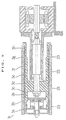
- the conventional bobbin holder 10 is fixed to the extreme left end portion of a bobbin holder shaft 14 directly coupled to a motor shaft 12 through a coupling 13, and comprises a rotary cylinder 15, a plurality of flexible rings 16a to 16h (eight rings are shown in the drawing) inserted to the outer periphery of the rotary cylinder, cylindrical spacers 17a to 17g for positioning the flexible rings, a front cover 17 for pushing the flexible rings 16a to 16h in the right-hand direction in the drawing and a push mechanism 20 comprising a coned disc spring 18 and a piston 19, for imparting the push force to the front cover in the right-hand direction in the drawing.
- Feed ports 12a and 14a for supplying compressed air are disposed in the motor shaft 12 and in the bobbin holder 14, respectively, and the flexible rings 16a to 16h are integrated by bonding a steel ring 22 to both side surfaces of a rubber ring 21 as shown in Fig. 12.
- the thickness of the flexible ring 16 according to the prior art becomes as great as 7 to 10 mm, and flexible rings having a smaller thickness cannot be used practically because deformation and the diameter increase becomes smaller and the bobbins cannot be firmly gripped.
- the constituent element that affects most greatly the determination of the specification of the bobbin holder 10 is the rotary cylinder 15 having the greatest length among the constituent elements, and its critical speed Nc, or in other words, its natural frequency, generally expressed by the following formula 1. The greater this value, the higher becomes the critical speed of the bobbin holder as a whole. Nc ⁇ 1 L 2 ⁇ I A ⁇ E ⁇
- the sectional area A and the second moment of area I of the rotary cylinder have the following relation with the outer diameter Ds and the inner diameter Di of the rotary cylinder, respectively: A ⁇ (Ds 2 -Di 2 ), I ⁇ (Ds 4 -Di 4 ) Accordingly, the formula 1 can be changed as follows: Nc ⁇ Ds 2 +Di 2 L 2 ⁇ E ⁇
- symbols E and ⁇ represent a Young's modulus and a specific gravity, respectively, and they are determined by the constituent material of the rotary cylinder 15. In the case of iron, they are generally 21,000 kg/mm 2 and 7.85, respectively, and it is not greatly expected at present that the critical speed Nc can be increased to a great value due to these values.
- the thickness of the rotary cylinder is set to about 4 to about 5 mm in order to insure precision of machining, at present.
- the reduction of the thickness to such a level cannot accomplish the improvement of the critical speed which can cope with the future need (refer to Japanese Patent Laid-Open No. 196268/1987, for example).
- the prior art technologies have not been able to find out any effective means for providing a bobbin holder for taking up the yarn at a high speed under the state where a large number of bobbins having a small diameter are held, by increasing the critical speed Nc of the rotary cylinder 15 to a high speed range without increasing the inner diameter of the bobbins.
- the present invention has been completed in view of the background described above and is directed to provide an elongated bobbin holder capable of take-up at a high speed without increasing an inner diameter of bobbins, and a take-up device equipped with the bobbin holder.
- the present invention has been completed so as to accomplish a technology capable of increasing the outer diameter of the rotary cylinder without increasing the inner diameter of the bobbins to be fitted to the bobbin holder. More concretely, the present invention aims at the provision of a bobbin holder capable of setting the difference T between the outer diameter Ds of the rotary cylinder and the inner diameter Db of the bobbin to not greater than about 10 mm, and a take-up device using the bobbin holder.
- the invention of claim 1 relates to a bobbin holder comprising a driving shaft, a rotary cylinder which is rotated by said driving shaft and over an outer peripheral surface of which a plurality of bobbins are fitted and bobbin gripping means, characterised in that a difference ⁇ between an outer diameter Ds of said rotary cylinder and an inner diameter Db of a bobbin is not greater than 10 mm, and that a thickness t at an end portion of said rotary cylinder satisfies a relation of 0 ⁇ t ⁇ 0.04 Ds wherein said outer diameter Ds is in at least a part of a range not greater than 70% of a distance from an end face of said rotary cylinder to an end face of an engagement portion with said driving shaft.
- the term "spring member exhibiting substantially a ring-like shape” represents the means which undergoes deformation and the increase in diameter by the push force from the side surface direction and grips the bobbins from the side of the inner peripheral surface.
- the material of the spring member is not particularly limited so long as it has a property such that it can easily expand in the direction of the outer diameter and can undergo deformation and the increase of its diameter, has a restoring property in the direction of the inner diameter and has durability sufficient to withstand repeating loads of frequent compression and restoring.
- the spring member is preferably a shaped spring consisting of a molded plate of a spring steel, a stainless steel, or hard plastics. A spring steel is preferable because elasticity is required.
- the thickness is preferably from 0.01 to 0.5 mm and more preferably from 0.05 to 0.2 mm.
- the width in the direction of the driving shaft is not particularly limited, but the observation acquired by the inventors of the present invention reveals that the width is preferably from 1/10 to 1/5 times the outer diameter Ds of the rotary cylinder.
- the sectional shape of the spring member may be convexed in at least the direction of the outer diameter so as to grip the bobbins.
- the shapes shown in Figs. 5(A) and 5(B) may also be used.
- the height H of the convexity of the spring member 30 is preferably from 0.3 to 1.5 mm in view of machinability and ease of deformation and the diameter increase by the push force from the side surface direction.
- a notch portion to be expanded is preferably formed in the spring member, but the shape may be an elongated hole 30b shown in Fig. 3 or a mere slit.
- Such holes or slits may be disposed slantingly or non-uniformly.
- the arrangement and the shape are not particularly limited so long as the notches can expand when the spring member undergoes deformation and increases its diameter.
- the term "ring-like” means a "substantially ring-like” state as a whole.
- the spring member need not always form completely one continuous circular body but may be discontinuous and may form a "ring-like" shape as a whole. This also holds true of the rigid ring which will be described later.
- a thin plate is first photoetched or punched and is then shaped into the ring form by electron beam welding. Further, the formation of the convex portion and correction of the degree of cylindricality are carried out by saddle machining. Punching may be used most preferably for machining the thin plate due to production costs.
- the outer peripheral surface of the spring member which comes into contact with the inner peripheral surface of the bobbin when the spring member undergoes deformation and increases its diameter is preferably coated with a rubber material in order to more firmly grip the bobbins, and the material is preferably a synthetic resin such as a silicone rubber or urethane rubber and is more preferably a nitrile rubber having high chemical resistance and excellent aged deterioration.
- the rigid rings disposed on both side ends of the spring member are means for fixing the spring member and loosely fitting it to the rotary cylinder.
- the material may be a metallic material such as an ordinary steel or aluminum, or hard plastics.
- General fixing means such as press-in, welding, etc, can be employed to fix the rigid rings to the spring member, but the combined use of press-in with fastening is most preferred because the production cost is relatively low and deformation does not occur after fixation.
- the sectional shape of the rigid ring is most typically represented by L-shape indicated by reference numeral 38 in Fig. 2. Besides this L-shape, it may be a mere rectangular section or may be equipped with a slit formed on the rectangular section so as to receive the spring member. However, from the aspects of the production cost and ease of the fixing work, the L-shape described above is most preferred. If the width W of the rigid ring is too great, the production cost rises and a problem will occur when handling them, and if it is too small, on the contrary, the fitting and fixing property to the spring member drops. Accordingly, the width W is preferably from 1/2 to 1/10 times and more preferably from 1/2.5 to 1/5 times the width of the spring member.
- the flexible ring used for the bobbin holder according to the present invention is equipped with the spring member and the rigid rings described above, and its outer diameter is smaller by about 0.5 to 1 mm than the inner diameter of the bobbin so that the bobbins can be easily removed. Its thickness in the radial direction is preferably as small as possible because the outer diameter of the rotary cylinder can be increased as much, but is preferably at least 1 mm and less than 5 mm and is more preferably from 2 to 4 mm in view of workability and the work efficiency.
- the flexible ring explained above does not undergo buckling when it is pushed in the axial direction, though its thickness is reduced, but because the spring member undergoes deformation and increases its diameter in the direction of the outer diameter and comes into close contact with the inner peripheral surface of the bobbins with the strong force, the flexible ring can firmly grip the bobbins from the inner peripheral surface side, unlike the flexible ring according to the prior art wherein the material at the portion for gripping the bobbins from the inner peripheral surface side is made merely of a flexible material such as a rubber.
- the bobbins When the bobbins are released, too, the bobbins can be easily removed due to the diameter reduction function brought forth by the restoring force of the flexible ring. Furthermore, when the coarseness of the inner peripheral surface of the rigid ring is set to 0.2 to 100 S (surface coarseness JIS B0661-1970) and its surface hardness is set to Hv 200 to 900 (JIS B7725-1976), the frictional resistance between the rotary cylinder and the flexible ring can be remarkably reduced, so that the bobbins can be released more easily.
- the thickness T of the flexible ring as the bobbin gripping means in the radial direction can be remarkably reduced to 1 to 5 mm in comparison with the conventional thickness of 7 mm, and the outer diameter Ds of the rotary cylinder can be increased as much.
- the outer diameter of the flexible ring is preferably set to about 60 to about 150 mm when a yarn take-up device having a take-up speed of at least 5,000 m/min and a bobbin holder length of 800 to 1,500 mm is constituted by using this flexible ring.
- concavoconvexities on the contact surface between the cylindrical spacer and the flexible ring or the rubber-like coating needs be disposed on at least one of the side surfaces of these members.
- the concavo-convexities on the contact surface have preferably the structure which does not generate slip, such as a tooth-shape, a wave shape, pins, and so forth.
- a material having a higher coefficient of friction than a metal such as soft plastics, rubbers and viscous paints, is preferably used for the rubber-like coating.
- the invention of claim 1 relates to a bobbin holder comprising a driving shaft and a rotary cylinder which is rotated by the driving shaft.
- the term “driving shaft” represents a shaft body interposed as means for transmitting rotating motion to the rotary cylinder and includes the bobbin holder shaft 14 shown in Fig. 11, too, but it may be integrally constituted with the motor shaft 12 into one unit.
- engagement portion with the rotary cylinder includes not only the case where the rotary cylinder and the driving shaft are constituted as mutually separate members as shown in Fig. 11 but also the case where both of them are integrally formed as shown in Fig. 13.
- the rotary cylinder is the means, to the outer peripheral surface of which, the cylindrical bobbins are fitted, which determines the bobbin positions and fix them, and transmits the rotation from the driving shaft to the bobbins.
- the engagement portion may be disposed at any position inside the rotary cylinder. Generally, an engagement portion is disposed at a substantial center or at one of the end portions of the rotary cylinder, but a plurality of such engagement portions may be disposed, as well. However, one engagement portion is preferably disposed from the aspects of machinability and the machining cost, and most preferably, one engagement portion is disposed at a substantial center of the rotary cylinder.
- the material of the rotary cylinder is not particularly limited so long as it can accomplish the object described above. It is possible to use, for example, steel materials such as chromimum-molybdenum steel, steels for mechanical structures, non-ferrous materials such as duralmin, titanium oxide, etc, and non-metallic materials such as carbon fiber reinforced resins, rigid plastics, and so forth. A plurality of these materials may be used in combination. Particularly preferred among them is the steel material from the aspect of machinability and the production cost, and most preferred is the chromium-molybdenum steel.
- the difference ⁇ (Db - Ds) between the outer diameter Ds of the rotary cylinder and the inner diameter Db of the bobbin is not greater than 10 mm. More concretely, it is very important that the difference ⁇ of the diameters is set to 1 to 10 mm and at the same time, and the inner diameter of the rotary cylinder is so set that the thickness at the end portion is smaller than the thickness in the vicinity of the boss portion.
- the thickness t of the rotary cylinder preferably satisfies the relation 0 ⁇ t ⁇ 0.04Ds with the outer diameter Ds of the rotary cylinder at at least a part of the range where the distance from the end face is not greater than 70% of the distance from the end face to the end face which is most approximate to the engagement portion with the driving shaft. More preferably, the thickness t satisfies the relation 1.5 mm ⁇ t ⁇ 3 mm with the range described above.
- the present invention does not contemplate a snap ring groove, an escape groove for a cutting tool, etc, from the aspect of machining.
- the distance La represents the distance from the end face of the rotary cylinder to the nearest end face of the engagement portion on the front cover side of the rotary cylinder
- the thickness t of the rotary cylinder preferably falls within the range of 0 ⁇ t ⁇ 0.04Ds at at least a part of the range where the distance Lx is not greater than 70% of La. This also holds true of the distances Lb and Ly of the rotary cylinder on the motor side.
- the length of the rotary cylinder in the axial direction is preferably from 800 to 1,500 mm in the same way as in the first embodiment.
- U.S. Patent Specification No. 4,830,299 discloses the construction wherein chuck pins comes out from, and into, a plurality of holes formed in the outer peripheral surface of the rotary cylinder and grip the inner peripheral surfaces of the bobbins.
- the difference between the outer diameter of the rotary cylinder and the inner diameters of the bobbins inserted into the bobbin holder can be set to an extremely small value of not greater than 1 mm, but in order to dispose the chuck pins, through-holes are necessary throughout the entire length and the entire periphery of the rotary cylinder, so that the strength drops and the possibility of stress concentration occurs. Moreover, the production cost becomes higher. Accordingly, the bobbin gripping means of Fig. 1 using the flexible ring shown in Figs. 2 and 5 is preferred.
- the present invention can increase the diameter of the rotary cylinder without increasing the inner diameter of the bobbin and can therefore increase the sectional second moment of area. Accordingly, the present invention can elevate the critical speed of the rotary cylinder to the high speed range.
- the take-up device equipped with the bobbin holder described above can accomplish high speed take-up, which has not been accomplished by the prior art technologies, and can expand the take-up range because of the effect of the increase of the critical speed of the bobbin holder.
- the difference between the outer diameter of the rotary cylinder provided to the bobbin holder and the inner diameter of the bobbins to be fitted on the bobbin holder is kept below 10 mm, and the thickness of the rotary cylinder near the end portion is made smeller than its thickness near engagement portion between the rotary cylinder and the driving shaft.
- the present invention makes it possible to elevate the critical speed to the high speed range and to produce the bobbin holder with a higher level of precision.
- the take-up device equipped with the bobbin holder can accomplish high speed take-up which has not been accomplished by the prior art, and can expand the take-up range.
- Fig. 1 is a longitudinal sectional view of the first embodiment wherein a bobbin holder according to claim 1 of the Scope of Claim for Patent is used for a yarn take-up device.
- a bobbin holder 1 for gripping a bobbin 23 comprises a rotary cylinder 2 having a boss portion 7 thereinside, a plurality of (eight, in the drawing) flexible rings 3a to 3h inserted into a longitudinal direction of the outer periphery of this rotary cylinder, cylindrical spacers 4a to 4g for positioning the flexible rings so that their fitting positions exist in the vicinity of both end portions of the bobbin 23, a front cover 5 for pushing the flexible ring 3a at the extreme left in the right-hand direction in the drawing, and a push mechanism 6 including a coned disc spring 6a, a piston 6b and an O-ring 6c.
- the rotary cylinder 2 is made of a chrominum-molybdenum steel which has widely been used generally as a structural member for high speed rotary bodies.
- the boss portion 7 as an engagement portion of the rotary cylinder 2 is fastened to one of the ends of a bobbin holder shaft 8 by a nut 8c and the bobbin holder shaft 8 is supported by two bearings 31 fitted into a ring-like support 9, the rotary cylinder 2 is allowed to freely rotate.
- the other end of the bobbin holder 8 is directly coupled to a motor shaft 32 of a motor 11 by a coupling 33 and the motor shaft 32 is rotatably supported by two bearings 35 fitted to a motor housing 34. Further, an armature 36 is fixed to the motor shaft 32.
- a stator 37 is disposed in the motor housing 34 and transmits a driving force or a braking force to the bobbin holder 1 in cooperation with the armature 36.
- Reference numeral 8a denotes a compressed air feed port, and when compressed air is supplied to the motor shaft 32 from a compressed air feed source 50 such as a compressor or a blower, the piston 6b and the front cover 5 are moved to the left in the drawing, thereby releasing grip of the bobbin 23.
- each of the flexible rings 3a to 3h comprises a spring member 30, a pair of rigid rings 38 having an L-shaped sectional shape and rubber members 39, 40.
- the spring member 30 and the rigid ring 38 may be spaced apart from each other, they are preferably combined as shown in the drawing.
- the spring member 30 is made of a material such as a spring steel, a stainless steel and rigid plastics, and has a thickness of 0.12 mm and a width of 20 mm. It includes an elongated hole 30b which is so expanded by a push force from the side surface direction as to increase its diameter and deform.
- the spring member 30 is bent into a convex shape having a crossing angle ⁇ 1 so that it is more likely to swell in the direction of the outer circumference and its height H in the radial direction is about 0.8 mm throughout the full periphery.
- Thirty-four elongated holes 30b are disposed uniformly throughout the entire periphery having a major diameter of 14 mm and a minor diameter of 2 mm.
- the crossing angle ⁇ 1 is preferably from 90 to 180° so as to reduce the stroke by the push mechanism 6 and is more preferably set to 140 to 175° at which a so-called toggle mechanism can be utilized, in consideration of the bobbin gripping force.
- a production method of the spring member 30 comprises shaping the outer shape into a flat sheet shape by photoetching, forming the ring form by electron beam welding, and correcting the cylindricality and at the same time, forming the convexity by effecting saddle machining.
- the solid ring 38 is made of the stainless steel. After the stainless steel is shaped into the L shape by cutting, the spring member 30 described above is pushed into it. When a large number of solid rings 38 are produced the rigid rings 38 are produced more preferably by die-casting an aluminum material.
- the rubber members 39, 40 are means for firmly gripping the bobbin 23 on its inner peripheral surface when the spring member 30 expands in the direction of the outer diameter. They are so disposed as to encompass the spring member 30. Though its material is not limited in particular, a nitrile rubber having a rubber hardness of 20 to 60 degrees is preferred. After the spring member 30 is pushed into the rigid ring 38, the rubber members 39, 40 are simultaneously vulcanized and shaped.
- Each of the flexible rings 3a to 3h produced in the way described above has an outer diameter of 60 to 150 mm and a thickness of at least 1 but less than about 5 mm in the radial direction.
- the outer diameter of the flexible rings 3a to 3h is smaller by about 0.5 to about 1 mm than the inner diameter of the bobbin 23 so as to facilitate bobbin release.
- the cylindrical spacers 4a to 4g are made of aluminum, and the outer diameter is by about 0.5 to about 1 mm smaller than the inner diameter of the bobbin 23 to be gripped, in the same way as the flexible rings 3a to 3h in consideration of tightening of winding.
- the material of the cylindrical spacers may be an ordinary iron steel or a light-weight material such as plastics or carbon fiber reinforced resins.
- the bobbin 23 is gripped concentrically and tightly by the rotary cylinder 2.
- the rotary cylinder 2 rotates while gripping the bobbin 23.
- the bobbin holder 1 shown in Figs. 1 to 4 is constituted by the rotary cylinder 2 having a length of 1150 mm by setting the outer diameter of the flexible ring 3 to 93.2 mm and its width to 25 mm so that eight bobbins 23 having an inner diameter of 94 mm and a length of 150 mm can be inserted.
- the thickness T of the flexible ring according to the prior art shown in Figs. 11 and 12 cannot be reduced below about 7 mm and for this reason, the outer diameter of the rotary cylinder 2 is 80 mm.
- the diameter can be increased to 87 mm in this embodiment because the thickness of the flexible ring 3 in the radial direction can be reduced.
- the bobbin holder could be rotated at 17,500 rpm as represented in Fig. 6.
- the bobbin holder according to the prior art which had an outer diameter of 80 mm could be roated at only up to 14,800 rpm.
- the present invention could make high speed take-up of 5,500 m/min corresponding to the improvement of 800 m/min brought forth due to the improvement in the critical speed.
- the bobbin gripping force of the bobbin holder 1 was measured under the stationary state of the bobbin holder.
- the measurement method was as follows. A rotary cylinder to which eight bobbins 23 having an inner diameter of 94 mm and a length of 150 mm was assembled in the same way as the bobbin holder used for the rotation test shown in Fig. 6. After eight bobbins were inserted, a rotating torque was applied to each of the bobbins while a mechanical brake was applied to the motor shaft 32 shown in Fig. 1. The rotating torque at the time when slip started occurring in the bobbin in the rotating direction was measured, and this value was used as the gripping strength of each flexible ring.
- the flexible ring 3 according to the present invention has a bobbin gripping force equivalent to that of the flexible ring 16 according to the prior art. Further, whereas the drop of the bobbin gripping force was observed on the motor side as in the flexible rings having the bobbin numbers VII and VIII according to the prior art, the flexible rings according to the present invention could obtain a substantially uniform gripping force.
- the spring member is so shaped as to protrude in the direction of the outer shape. Therefore, its diameter increases only in the direction of the outer shape when the spring member receives the push force from the side surface.
- the flexible ring according to the prior art has the structure shown in Fig. 12(A). Therefore, when the push force acts from the direction of the side surface, deformation occurs in the direction of the inner peripheral surface, too, as shown in Fig. 12(B).
- the coarseness of the inner peripheral surface of the rigid ring 38 it is preferred to set the coarseness of the inner peripheral surface of the rigid ring 38 to 0.2 to 100 S (surface coarseness JIS B0661-1970) and the surface hardness HV to 200 to 900 (JIS B7725-1976).
- the flexible rings 16 according to the prior art permanent deformation of about 1 mm occurred in the direction of the outer diameter in the coarse of use for about 5 months, and catch occurred when the bobbins were inserted.
- the flexible ring 3 according to the present invention kept the dimension and the gripping force which hardly changed even after the passage of about one year from the time of fitting due to the effect of the spring member 30, and could continue take-up.
- Fig. 7 is a longitudinal sectional view of the bobbin holder 1a according to claim 10 of the Scope of Claim for Patent.
- the bobbin holder relates to the second embodiment of the present invention and employs the same structure as that of the first embodiment with the exception of the structure of the rotary cylinder 2a.
- Fig. 8 is a view showing the sectional shape and the principal dimension of the rotary cylinder 2a as a characterizing feature of the present invention.
- the rotary cylinder 2a has a full length of 1,150 mm, is made of a chromium-bolybdenum steel and is equipped at is substantial center with the boss portion 7 as the engagement portion with the bobbin holder shaft 8 not shown in the drawing, in the same way as in the first embodiment. Further, the thickness t of both end portions 2b of the rotary cylinder is smaller than the thickness of the portion 2c near the engagement portion, and the thickness is 2 mm from the distal end to a distance of 250 mm on the side of the front cover 5, and is 2.5 mm from the distal end to a distance of 400 mm on the motor side.
- the portion of the rotary cylinder at which the thickness t is reduced may be at least one of its end portions. However, it is of course better to reduce the thickness at both end portions.
- the berm "thickness of the portion 2c near the engagement portion" means the thickness of the cylinder 2c in the proximity of the boss portion 7.
- the limit thickness is about 3.5 mm which is the limit of the second moment of area, but because the outer diameter is increased in the rotary cylinder 2a according to the present invention, the thickness can be reduced to 2.5 mm and at the same time, both outer and inner diameters can be increased as can be clearly seen from the afore-mentioned formula 2, so that a bobbin holder having a higher critical speed, that is, a bobbin holder capable of coping with a higher speed, can be obtained.
- bobbins 23 were inserted into the bobbin holder 1a having the rotary cylinder 2a described above and were rotated.
- Fig. 9 shows the result.
- the critical speed of the bobbin holder could be further improved from the first embodiment and could rotate in a high speed range of 19,600 rpm, and high speed take-up at 6,000 m/min could be accomplished in taking up the yarn.
- the improvement of 4,800 rpm in terms of the number of revolutions and 1,300 m/min in terms of the take-up speed of the yarn could be accomplished.
- Symbols A to C in the diagram represent the rotation test results by the prior art, the first embodiment and the second embodiment of the present invention, respectively.
- the winding test of the yarn was carried out in the following way.
- two types of rotary cylinders that is, a type having the end face shape according to the prior art and another in which the thickness at the end portions was smaller than the thickness near the engagement portion, were produced for each of the rotary cylinders having outer diameters Ds of 83 mm, 84 mm, 85 mm and 86 mm, respectively.
- Each of these rotary cylinders was assembled into a bobbin having an inner diameter of 94 mm and a full length of 1,200 mm by the flexible ring 3 having the same structure as that of Fig. 2.
- the bobbin holder and the take-up device according to the present invention use the flexible ring 3 of the first embodiment, they do not at all involve the problems of the bobbin gripping force and the restoring force at the time of release and have excellent performance in long term durability. Accordingly, continuous take-up of the yarn without inviting the stop of the apparatus for frequent change of the flexible ring can be accomplished.
- the bobbin holder and the take-up device using the bobbin holder according to the present invention can be naturally used for winding linear materials such as a yarn and a steel wire to the bobbin, and can be suitably applied also to sheet-like materials such as a synthetic resin film, woven and knitted fabrics, non-woven fabrics and paper.
- the bobbin holder and the take-up device equipped with the bobbin holder described in claims 1 and 10 of the present invention can provide the following excellent functions and effects.
Abstract
Description
- (1) As to the item 1 ○, however, the length L is a value which is substantially determined by the full length of the bobbin 23 to be gripped, though it is designed to be as short as possible so as to improve the critical speed of the rotary cylinder 15. When eight bobbins each having a length L of 150 mm are gripped, for example, the length of the rotary cylinder 15 must essentially be a value approximate to the total length of the bobbins, i.e. 1,200 mm. Therefore, the length of from about 1,150 to about 1,200 is generally used, and this value cannot be reduced physically.
- (2) As to the item 2 ○, the diameters of the flexible rings 16a to 16h to be loosely fitted must he generally increased in order to increase the outer diameter Ds. This means essentially that the bobbins used must have a greater diameter, too. However, the increase in the diameter of the bobbins directly increases the cost of the bobbins, and the effects brought forth by the higher take-up speed and the improvement of productivity due to the increase of the critical speed (Nc) are offset by the increase of the bobbin cost. Here, one of the effective means would be the one that reduces as much as possible the thickness T of each flexible ring 16a to 16h in the radial direction and increases the outer diameter of the rotary cylinder 15. In other words, if the thickness of the flexible ring can be reduced without changing the inner diameter Db of the bobbins used, the outer diameter Ds of the rotary cylinder can be increased as much, the critical speed of the bobbin holder can be increased and rotation at a higher speed becomes possible.However, when the thickness T of each flexible ring 16a to 16h in the radial direction is merely reduced, the following problems occur. When eight bobbins 23 are held in the axial direction, for example, two flexible rings 16a to 16h are generally used for each bobbin and sixteen flexible rings, in total, are used. Each bobbin 23 is gripped by deformation of the flexible rings 16a to 16h in the direction of the outer diameter due to the push force from the front cover 17 as described above. When the thickness T is reduced on the basis of the concept described above, the total volume of the rubber ring 21 decreases and expansion in the direction of the outer diameter, capable of firmly gripping the bobbins 23 cannot be obtained even when the push force from the side surface direction acts. When the rubber ring 21 is merely elongated in the axial direction so as to compensate for the decrease of the volume resulting from the decrease of the thickness, the rubber ring 21 becomes a cylinder having a small thickness. Accordingly, it undergoes buckling when the push force acts on it and cannot expand in the direction of the outer diameter sufficiently for firmly gripping the bobbins 23.On the other hand, the reduction of the thickness T of the flexible ring invites the problem in bobbin release. Even when the push force of the front cover 17 is released, the restoring force of the rubber ring 21 becomes small due to the reduction of the thickness of the flexible rings 16a to 16h. Though the rubber rings 21 of one or two flexible rings 16a, 16b near the front cover 17 return to their original shape, the diameter of the flexible rings 16g, 16h, etc, remote from the front cover 17 remains expanded because they cannot overcome the frictional force between the inner peripheral surface of the bobbins and the outer peripheral surface of the rotary cylinder 15, so that faulty bobbin removal occurs. As described above, the reduction of the thickness T of the flexible rings 16a to 16h in the radial direction so as to improve the critical speed of the rotary cylinder 15 to a high speed range cannot be accomplished as long as the prior art technology is employed.Therefore, several prior art technologies are known as technologies which give specific design considerations to such a flexible ring. For example, U.S. Patent Specification No. 5,217,175 changes the sectional shape of the rubber ring that constitutes the flexible ring.However, because the flexible ring relies only on the restoring force of the flexible material such as a rubber for the force of gripping the bobbin from the inner peripheral surface side, a sufficient gripping force cannot be obtained when the thickness is reduced. Further, the rubber ring in the means described above is shaped into the size of the outer diameter for gripping the bobbin under the state in which the stress from the direction of the side surface does not act, and when the bobbins are pulled out and removed, a tensile force is allowed to act on both side surface of the flexible ring so as to reduce the diameter and to cause deformation. In other words, since the bobbins are gripped under the state where any external force does not act, faulty bobbin gripping are likely to occur due to buckling of the rubber in the course of use for a long time and wear of its outer peripheral surface.In the bobbin holder described in U.S. Patent Specification No. 3,923,261, the bobbin gripping portion is made only of a rubber material and applies the tensile force at the time of pull-out of the bobbins. Therefore, this Prior art involves the same problem as that of the flexible ring described above.Accordingly, means for accomplishing the reduction of the thickness of the flexible ring, that is, means for increasing the outer diameter Ds of the rotary cylinder 15 without changing the inner diameter Db of the bobbins used, has not been accomplished at the present moment.
- (3) Finally, in order to increase the inner diameter Di of the rotary cylinder 15 described in the item 3 ○, the thickness t may be reduced, but when the thickness is excessively reduced, a high-precision machining cannot be conducted and unbalance is likely to occur, so that excessive vibration is likely to occur at the time of high speed rotation. The decrease of the thickness t decreases the mechanical strength. Therefore, the flexible ring cannot withstand the centrifugal force at the high rotating speed, the possibility of mechanical damage exists, and destruction of the rotary cylinder might occur in the worst case.
| Measurement Result of Bobbin Gripping Force | |||
| Bobbin No. | Bobbin gripping force (kg·m) | ||
| 1 ○ Example | 2 ○ Comp. Example 1 | 3 ○ Comp. Example 2 | |
| I | 2.4 | 2.5 | 1.4 |
| II | 2.3 | 2.4 | 1.3 |
| III | 2.2 | 2.4 | 1.1 |
| IV | 2.4 | 2.1 | 0.9 |
| V | 2.3 | 2.2 | 0.8 |
| VI | 2.2 | 2.1 | 0.7 |
| VII | 2.3 | 2.0 | 0.7 |
| VIII | 2.2 | 1.9 | 0.5 |
- 1 ○ Example:
- outer diameter 93.2, inner diameter 87, width 25 (mm), material: nitrile rubber, hardness 40 degrees, with spring member
- 2 ○ Comparative Example:
- outer diameter 93.2, inner diameter 80, width 13 (mm), material: nitrile rubber, hardness 40 degrees, without spring member
- 3 ○ Comparative Example:
- outer diameter 93.2, inner diameter 87, width 13 (mm), material: nitrile rubber, hardness 40 degrees, without spring member
| Results of Take-up Test | ||||||
| Test No. | Condition | Effect | ||||
| bobbin inner diameter Db mm | outer diameter of rotary cylinder Ds mm | diameter difference δ mm | end shape of rotary cylinder | Take-up speed m/min | ||
| 5000 | 5500 | |||||
| 1 ○ | 94 | 83 | 11 | piror art | X | X |
| 2 ○ | 94 | 83 | 11 | thin thickness | ▵ | X |
| 3 ○ | 94 | 84 | 10 | prior art | ○ | ▵ |
| 4 ○ | 94 | 84 | 10 | thin thickness | o ○ | ○ |
| 5 ○ | 94 | 85 | 9 | prior art | o ○ | ▵ |
| 6 ○ | 94 | 85 | 9 | thin thickness | o ○ | o ○ |
| 7 ○ | 94 | 86 | 8 | prior art | o ○ | ○ |
| 8 ○ | 94 | 86 | 8 | thin thickness | o ○ | o ○ |
- o ○:
- take-up was satisfactory, vibration was less than 5 µm.
- ○:
- take-up could be made, vibration was within an allowable range of 5 to 10 µm.
- ▵:
- Though rotation could be made, take-up could not be made because the vibration level was too high. Vibration was at least 30 µm.
- X:
- Rotation could not be made.
Claims (12)
- A bobbin holder (1) comprising a driving shaft (8), a rotary cylinder (2) which is rotated by said driving shaft (8) and over an outer peripheral surface of which a plurality of bobbins (23) are fitted and bobbin gripping means, characterised in that a difference δ between an outer diameter (Ds) of said rotary cylinder (2) and an inner diameter (Db) of a bobbin (23) is not greater than 10 mm, and that a thickness (t) at an end portion of said rotary cylinder (2) satisfies a relation of 0 < t < 0.04 Ds wherein said outer diameter (Ds) is in at least a part of a range not greater than 70% of a distance from an end face of said rotary cylinder (2) to an end face of an engagement portion with said driving shaft (8).
- A bobbin holder according to claim 1, wherein the outer diameter (Ds) of said rotary cylinder (2) is at least 84 mm and less than 94 mm.
- A bobbin holder according to claim 1 or 2, wherein said bobbin gripping means is a flexible ring (3a to 3h) which comprises (A) a spring member (30) exhibiting substantially a ring-like shape and shaped in such a manner that the sectional shape thereof in the direction of said driving shaft (8) is convexed in at least the direction of the outer diameter; and (B) rigid rings (38) disposed on both side ends of said spring member (30).
- A bobbin holder according to claim 3, wherein the thickness (T) of said flexible ring in the radial direction is at least 1 mm and less than 5 mm.
- A bobbin holder according to claim 4, wherein the length of said rotary cylinder (2) in the axial direction is from 800 to 1,500 mm.
- A bobbin holder according to any of claims 1 to 5, wherein said rotary cylinder (2) comprises a cylinder (2b 2c) and a boss portion (7) disposed at a substantial center of the inside of said cylinder, and said driving shaft (8) is engaged at said boss portion.
- A bobbin holder according to any of claims 1 to 6, wherein said means for imparting the press force or the release force from the direction of the side surface to said flexible ring (3a to 3h) comprises a front cover disposed near at least one of the ends of said rotary cylinder (2) and pressing or releasing said flexible ring (3a to 3h) in the axial direction of said driving shaft (8) and moving mechanism for moving back and forth said front cover in the axial direction of said driving shaft (8).
- A bobbin holder according to claim 7, wherein said moving mechanism comprises a compression spring for imparting the press force in the axial direction to said flexible ring (3a to 3h) and pressurised fluid injection means (50) for imparting the release force in the opposite direction.
- A take-up device comprising:(A) said bobbin holder (1) according to any of claims 1 to 8;(B) bearing means for rotatably supporting said driving shaft (8) of said bobbin holder (1); and(C) driving means (11) of said bobbin holder (1), coupled to said driving shaft (8) of said bobbin holder (1).
- A take-up device according to claim 9, wherein an object of take-up of said take-up device is a linear material or a sheet-like material.
- A take-up device according to claim 10, wherein said linear material is a yarn or a steel wire.
- A take-up device according to claim 10, wherein said sheet-like material is a synthetic resin film, a fiber sheet-like material or paper.
Applications Claiming Priority (4)
| Application Number | Priority Date | Filing Date | Title |
|---|---|---|---|
| JP17423393A JP3198736B2 (en) | 1993-07-14 | 1993-07-14 | Bobbin holding device and bobbin holder |
| JP17423393 | 1993-07-14 | ||
| JP174233/93 | 1993-07-14 | ||
| EP94921092A EP0663365B1 (en) | 1993-07-14 | 1994-07-14 | Bobbin holder and wind-up gear provided with the same |
Related Parent Applications (1)
| Application Number | Title | Priority Date | Filing Date |
|---|---|---|---|
| EP94921092A Division EP0663365B1 (en) | 1993-07-14 | 1994-07-14 | Bobbin holder and wind-up gear provided with the same |
Publications (3)
| Publication Number | Publication Date |
|---|---|
| EP0850867A2 true EP0850867A2 (en) | 1998-07-01 |
| EP0850867A3 EP0850867A3 (en) | 1998-07-22 |
| EP0850867B1 EP0850867B1 (en) | 2001-12-05 |
Family
ID=15975053
Family Applications (2)
| Application Number | Title | Priority Date | Filing Date |
|---|---|---|---|
| EP94921092A Expired - Lifetime EP0663365B1 (en) | 1993-07-14 | 1994-07-14 | Bobbin holder and wind-up gear provided with the same |
| EP98200800A Expired - Lifetime EP0850867B1 (en) | 1993-07-14 | 1994-07-14 | Bobbin holder and take-up device equipped with the bobbin holder |
Family Applications Before (1)
| Application Number | Title | Priority Date | Filing Date |
|---|---|---|---|
| EP94921092A Expired - Lifetime EP0663365B1 (en) | 1993-07-14 | 1994-07-14 | Bobbin holder and wind-up gear provided with the same |
Country Status (8)
| Country | Link |
|---|---|
| US (1) | US5603463A (en) |
| EP (2) | EP0663365B1 (en) |
| JP (1) | JP3198736B2 (en) |
| KR (1) | KR100307242B1 (en) |
| CN (2) | CN1046917C (en) |
| DE (2) | DE69418692T2 (en) |
| TW (1) | TW307257U (en) |
| WO (1) | WO1995002551A1 (en) |
Cited By (3)
| Publication number | Priority date | Publication date | Assignee | Title |
|---|---|---|---|---|
| WO2009109554A1 (en) * | 2008-03-07 | 2009-09-11 | Oerlikon Textile Gmbh & Co. Kg | Bobbin holder |
| ITFI20090176A1 (en) * | 2009-08-03 | 2011-02-04 | Perini Fabio Spa | "WINDING MANDREL FOR THE PRODUCTION OF ROLLS OF RIBBED MATERIAL" |
| EP3385207A1 (en) * | 2017-04-07 | 2018-10-10 | Trützschler GmbH & Co. KG | Spindle for a winder |
Families Citing this family (19)
| Publication number | Priority date | Publication date | Assignee | Title |
|---|---|---|---|---|
| CH691856A5 (en) * | 1997-02-18 | 2001-11-15 | Rieter Ag Maschf | Chuck. |
| EP1241123A3 (en) * | 2001-03-16 | 2003-06-25 | Murata Kikai Kabushiki Kaisha | Bobbin chuck mechanism of a bobbin holder |
| EP1260475A1 (en) * | 2001-05-22 | 2002-11-27 | Toray Industries, Inc. | Yarn winding apparatus and method of producing a yarn package |
| JP4738636B2 (en) | 2001-05-29 | 2011-08-03 | 株式会社テクノ菱和 | Explosion-proof dustless ionizer |
| KR100876977B1 (en) | 2008-07-31 | 2009-01-07 | (주)아이.패스 | Mandril and device for manufacturing composite slide bearing |
| CN102372189B (en) * | 2011-09-29 | 2013-03-06 | 浙江海森纺机科技有限公司 | Spindle first component on braiding knotless net spooling machine |
| CN103193105B (en) * | 2013-04-24 | 2015-08-05 | 北京中丽制机工程技术有限公司 | The bobbin chuck shaft device of pivot shaft unit construction and filament winder |
| KR101435405B1 (en) * | 2013-07-16 | 2014-08-29 | (주)상일씨앤씨 | Metal undetectable reel-holder for label case |
| CN104120519B (en) * | 2014-08-08 | 2016-07-13 | 重庆恒进源茧丝绸有限公司 | A kind of spindle complemented one another and bobbin |
| KR101523640B1 (en) * | 2015-01-16 | 2015-05-28 | 최세흠 | Interlace rubber thread bobbin winder holder |
| CN105984750B (en) * | 2015-02-27 | 2019-02-12 | 成都瑞克西自动化技术有限公司 | The unilateral clamped-in style tape handler of tube |
| WO2016146465A1 (en) * | 2015-03-17 | 2016-09-22 | Oerlikon Textile Gmbh & Co. Kg | Winding spindle |
| CN106429623A (en) * | 2016-12-02 | 2017-02-22 | 张家港特恩驰电缆有限公司 | Cylinder ejecting shaft device |
| CN107217344B (en) * | 2017-07-27 | 2023-01-10 | 浙江龙一纺织有限公司 | Spindle |
| CN107651509B (en) * | 2017-11-14 | 2019-05-07 | 盐城聚一纺织有限公司 | A kind of weaving tube |
| CH715389A1 (en) * | 2018-09-27 | 2020-03-31 | Rieter Ag Maschf | Gripper for gripping a coil or bobbin tube. |
| CN109534092B (en) * | 2018-10-25 | 2021-06-08 | 国网浙江省电力有限公司磐安县供电公司 | Wire take-up device |
| DE102019105072A1 (en) * | 2019-02-28 | 2020-09-03 | Saurer Technologies GmbH & Co. KG | Coil pot storage |
| CN112575418B (en) * | 2020-11-23 | 2022-05-06 | 枣阳市博大纺织有限公司 | Single motor driven spindle textile machinery |
Citations (6)
| Publication number | Priority date | Publication date | Assignee | Title |
|---|---|---|---|---|
| US3813051A (en) * | 1972-06-15 | 1974-05-28 | Karlsruhe Augsburg Iweka | Bobbin-supporting chuck |
| JPS62196268A (en) * | 1986-02-20 | 1987-08-29 | Toray Ind Inc | Bobbin holder |
| EP0234844A2 (en) * | 1986-02-20 | 1987-09-02 | Toray Industries, Inc. | Yarn winder |
| JPH02225268A (en) * | 1989-02-23 | 1990-09-07 | Murata Mach Ltd | Bobbin holder in spinned yarn taking-up machine |
| EP0404363A2 (en) * | 1989-06-21 | 1990-12-27 | Rieter Scragg Limited | Winding devices |
| US5217175A (en) * | 1991-08-02 | 1993-06-08 | Barmag Ag | Winding spindle |
Family Cites Families (18)
| Publication number | Priority date | Publication date | Assignee | Title |
|---|---|---|---|---|
| DE225534C (en) * | ||||
| FR875630A (en) * | 1940-10-14 | 1942-09-29 | Jagenberg Werke Ag Soc | Winder or unwinder shaft for clamping round tubes |
| US2365980A (en) * | 1943-09-14 | 1944-12-26 | U S Textile Machine Company | Mandrel |
| US2941735A (en) * | 1955-12-13 | 1960-06-21 | Du Pont | Bobbin chuck |
| US3434675A (en) * | 1967-07-18 | 1969-03-25 | Panther Machine Corp | Adjustable roll-supporting spindle |
| US3497153A (en) * | 1968-10-02 | 1970-02-24 | Dusenbery Co John | Core support and drive |
| FR2245205A5 (en) * | 1973-05-18 | 1975-04-18 | Rhone Poulenc Textile | |
| JPS51151731U (en) * | 1975-05-27 | 1976-12-03 | ||
| JPS5718362Y2 (en) * | 1976-06-04 | 1982-04-16 | ||
| JPS54111579U (en) * | 1978-01-25 | 1979-08-06 | ||
| JPS54111579A (en) * | 1978-02-20 | 1979-08-31 | Sekisui Jushi Kk | Method of making thermoplastic resin tape having good transparency |
| JPS5718362A (en) * | 1980-07-10 | 1982-01-30 | Toshiba Corp | Semiconductor device and manufacture thereof |
| JPS60151863U (en) * | 1984-03-19 | 1985-10-09 | 帝人製機株式会社 | fluid coupling device |
| JPH0144533Y2 (en) * | 1986-09-09 | 1989-12-22 | ||
| IN169417B (en) * | 1986-11-11 | 1991-10-12 | Rieter Ag Maschf | |
| JPS6444533A (en) * | 1987-08-11 | 1989-02-16 | Nec Corp | Magnetic disk controller |
| JPH0679958B2 (en) * | 1988-10-07 | 1994-10-12 | 東レ株式会社 | Yarn winding device |
| JPH02305767A (en) * | 1989-05-17 | 1990-12-19 | Murata Mach Ltd | Yarn take-up machine in bobbin holder and extracting method for bobbins |
-
1993
- 1993-07-14 JP JP17423393A patent/JP3198736B2/en not_active Expired - Fee Related
-
1994
- 1994-07-14 EP EP94921092A patent/EP0663365B1/en not_active Expired - Lifetime
- 1994-07-14 DE DE69418692T patent/DE69418692T2/en not_active Expired - Fee Related
- 1994-07-14 KR KR1019950700935A patent/KR100307242B1/en not_active IP Right Cessation
- 1994-07-14 CN CN94190602A patent/CN1046917C/en not_active Expired - Fee Related
- 1994-07-14 EP EP98200800A patent/EP0850867B1/en not_active Expired - Lifetime
- 1994-07-14 US US08/392,742 patent/US5603463A/en not_active Expired - Lifetime
- 1994-07-14 DE DE69429373T patent/DE69429373T2/en not_active Expired - Fee Related
- 1994-07-14 WO PCT/JP1994/001154 patent/WO1995002551A1/en active IP Right Grant
- 1994-07-28 TW TW085202971U patent/TW307257U/en unknown
-
1998
- 1998-05-12 CN CNB981083188A patent/CN1137847C/en not_active Expired - Lifetime
Patent Citations (6)
| Publication number | Priority date | Publication date | Assignee | Title |
|---|---|---|---|---|
| US3813051A (en) * | 1972-06-15 | 1974-05-28 | Karlsruhe Augsburg Iweka | Bobbin-supporting chuck |
| JPS62196268A (en) * | 1986-02-20 | 1987-08-29 | Toray Ind Inc | Bobbin holder |
| EP0234844A2 (en) * | 1986-02-20 | 1987-09-02 | Toray Industries, Inc. | Yarn winder |
| JPH02225268A (en) * | 1989-02-23 | 1990-09-07 | Murata Mach Ltd | Bobbin holder in spinned yarn taking-up machine |
| EP0404363A2 (en) * | 1989-06-21 | 1990-12-27 | Rieter Scragg Limited | Winding devices |
| US5217175A (en) * | 1991-08-02 | 1993-06-08 | Barmag Ag | Winding spindle |
Non-Patent Citations (2)
| Title |
|---|
| PATENT ABSTRACTS OF JAPAN vol. 012, no. 045 (M-667), 10 February 1988 -& JP 62 196268 A (TORAY IND INC), 29 August 1987, * |
| PATENT ABSTRACTS OF JAPAN vol. 014, no. 536 (M-1052), 27 November 1990 -& JP 02 225268 A (MURATA MACH LTD), 7 September 1990, * |
Cited By (5)
| Publication number | Priority date | Publication date | Assignee | Title |
|---|---|---|---|---|
| WO2009109554A1 (en) * | 2008-03-07 | 2009-09-11 | Oerlikon Textile Gmbh & Co. Kg | Bobbin holder |
| US8523100B2 (en) | 2008-03-07 | 2013-09-03 | Oerlikon Textile Gmbh & Co. Kg | Bobbin holder |
| ITFI20090176A1 (en) * | 2009-08-03 | 2011-02-04 | Perini Fabio Spa | "WINDING MANDREL FOR THE PRODUCTION OF ROLLS OF RIBBED MATERIAL" |
| WO2011016071A1 (en) | 2009-08-03 | 2011-02-10 | Fabio Perini S.P.A. | Winding mandrel for the production of reels of web material |
| EP3385207A1 (en) * | 2017-04-07 | 2018-10-10 | Trützschler GmbH & Co. KG | Spindle for a winder |
Also Published As
| Publication number | Publication date |
|---|---|
| EP0663365A4 (en) | 1995-11-02 |
| DE69429373T2 (en) | 2002-07-18 |
| DE69418692T2 (en) | 1999-12-02 |
| DE69418692D1 (en) | 1999-07-01 |
| JPH0734334A (en) | 1995-02-03 |
| KR950703480A (en) | 1995-09-20 |
| CN1046917C (en) | 1999-12-01 |
| EP0850867B1 (en) | 2001-12-05 |
| JP3198736B2 (en) | 2001-08-13 |
| EP0663365A1 (en) | 1995-07-19 |
| CN1137847C (en) | 2004-02-11 |
| TW307257U (en) | 1997-06-01 |
| EP0663365B1 (en) | 1999-05-26 |
| WO1995002551A1 (en) | 1995-01-26 |
| US5603463A (en) | 1997-02-18 |
| CN1113382A (en) | 1995-12-13 |
| CN1205972A (en) | 1999-01-27 |
| EP0850867A3 (en) | 1998-07-22 |
| DE69429373D1 (en) | 2002-01-17 |
| KR100307242B1 (en) | 2001-12-17 |
Similar Documents
| Publication | Publication Date | Title |
|---|---|---|
| EP0850867B1 (en) | Bobbin holder and take-up device equipped with the bobbin holder | |
| AU713201B2 (en) | Rotary cutoff apparatus | |
| US5048005A (en) | Spindle clamp having a unitary lock member | |
| US11664746B2 (en) | Friction member to contact opposite member, method for manufacturing friction member, vibration-type actuator, and electronic device | |
| US20110035907A1 (en) | Hose Clamp | |
| EP0408040A1 (en) | Dynamic damper | |
| US6140741A (en) | Vibration type actuator | |
| EP0388206A1 (en) | Apparatus for driving rollers in roller hearth kiln | |
| US4993651A (en) | Yarn winding apparatus | |
| EP0335254B1 (en) | A bobbin holder | |
| JP3277734B2 (en) | Winding device | |
| JP2002089591A (en) | One-way clutch | |
| KR20230051666A (en) | linear drive | |
| JP3362713B2 (en) | Bobbin holding device and bobbin holder | |
| JP3270739B2 (en) | Bobbin holding device for winder | |
| CN1984830B (en) | Unloading method and rolling-up device for rolling up steel band having a rolling-up mandrel | |
| JPH07171646A (en) | Method for manufacture of machine supporting member | |
| JP3621066B2 (en) | Bobbin holding device for winder | |
| JPH11351297A (en) | Coned disc spring and main spindle device using coned disc spring thereof | |
| EP0524580A1 (en) | Roller supporting structure using a dynamic pressure | |
| JPS6013558Y2 (en) | Workpiece detection device | |
| SU1831760A3 (en) | Piezoelectric motor | |
| JP2751551B2 (en) | Yarn winding device | |
| JP3598437B6 (en) | Flexible foil type hydrodynamic fluid film type radial bearing | |
| JP2000143091A (en) | Thread winding device |
Legal Events
| Date | Code | Title | Description |
|---|---|---|---|
| PUAI | Public reference made under article 153(3) epc to a published international application that has entered the european phase |
Free format text: ORIGINAL CODE: 0009012 |
|
| PUAL | Search report despatched |
Free format text: ORIGINAL CODE: 0009013 |
|
| 17P | Request for examination filed |
Effective date: 19980401 |
|
| AC | Divisional application: reference to earlier application |
Ref document number: 663365 Country of ref document: EP |
|
| AK | Designated contracting states |
Kind code of ref document: A2 Designated state(s): DE FR GB IT |
|
| AK | Designated contracting states |
Kind code of ref document: A3 Designated state(s): DE FR GB IT |
|
| RIN1 | Information on inventor provided before grant (corrected) |
Inventor name: HAYASI, TOSHIRO Inventor name: SANO, TAKAO Inventor name: OKUMURA, KOZO, 802 FORM-GOJYO-NISINOTOIN, 527-1 Inventor name: KUMO, ICHIRO |
|
| GRAG | Despatch of communication of intention to grant |
Free format text: ORIGINAL CODE: EPIDOS AGRA |
|
| 17Q | First examination report despatched |
Effective date: 20010228 |
|
| RIN1 | Information on inventor provided before grant (corrected) |
Inventor name: HAYASI, TOSIHIRO Inventor name: SANO, TAKAO Inventor name: OKUMURA, KOZO, 802 FORM-GOJYO-NISINOTOIN, 527-1 Inventor name: KUMO, ICHIRO |
|
| GRAG | Despatch of communication of intention to grant |
Free format text: ORIGINAL CODE: EPIDOS AGRA |
|
| GRAH | Despatch of communication of intention to grant a patent |
Free format text: ORIGINAL CODE: EPIDOS IGRA |
|
| GRAH | Despatch of communication of intention to grant a patent |
Free format text: ORIGINAL CODE: EPIDOS IGRA |
|
| GRAA | (expected) grant |
Free format text: ORIGINAL CODE: 0009210 |
|
| AC | Divisional application: reference to earlier application |
Ref document number: 663365 Country of ref document: EP |
|
| AK | Designated contracting states |
Kind code of ref document: B1 Designated state(s): DE FR GB IT |
|
| PG25 | Lapsed in a contracting state [announced via postgrant information from national office to epo] |
Ref country code: FR Free format text: LAPSE BECAUSE OF FAILURE TO SUBMIT A TRANSLATION OF THE DESCRIPTION OR TO PAY THE FEE WITHIN THE PRESCRIBED TIME-LIMIT Effective date: 20011205 |
|
| RIN1 | Information on inventor provided before grant (corrected) |
Inventor name: HAYASI, TOSIHIRO Inventor name: SANO, TAKAO Inventor name: OKUMURA, KOZO, 802 FORM-GOJYO-NISINOTOIN, 527-1 Inventor name: KUMO, ICHIRO |
|
| REG | Reference to a national code |
Ref country code: GB Ref legal event code: IF02 |
|
| REF | Corresponds to: |
Ref document number: 69429373 Country of ref document: DE Date of ref document: 20020117 |
|
| PLBE | No opposition filed within time limit |
Free format text: ORIGINAL CODE: 0009261 |
|
| STAA | Information on the status of an ep patent application or granted ep patent |
Free format text: STATUS: NO OPPOSITION FILED WITHIN TIME LIMIT |
|
| EN | Fr: translation not filed | ||
| 26N | No opposition filed | ||
| PGFP | Annual fee paid to national office [announced via postgrant information from national office to epo] |
Ref country code: IT Payment date: 20080731 Year of fee payment: 15 |
|
| PGFP | Annual fee paid to national office [announced via postgrant information from national office to epo] |
Ref country code: GB Payment date: 20080716 Year of fee payment: 15 |
|
| PGFP | Annual fee paid to national office [announced via postgrant information from national office to epo] |
Ref country code: DE Payment date: 20090709 Year of fee payment: 16 |
|
| GBPC | Gb: european patent ceased through non-payment of renewal fee |
Effective date: 20090714 |
|
| PG25 | Lapsed in a contracting state [announced via postgrant information from national office to epo] |
Ref country code: GB Free format text: LAPSE BECAUSE OF NON-PAYMENT OF DUE FEES Effective date: 20090714 |
|
| PG25 | Lapsed in a contracting state [announced via postgrant information from national office to epo] |
Ref country code: IT Free format text: LAPSE BECAUSE OF NON-PAYMENT OF DUE FEES Effective date: 20090714 |
|
| PG25 | Lapsed in a contracting state [announced via postgrant information from national office to epo] |
Ref country code: DE Free format text: LAPSE BECAUSE OF NON-PAYMENT OF DUE FEES Effective date: 20110201 |
|
| REG | Reference to a national code |
Ref country code: DE Ref legal event code: R119 Ref document number: 69429373 Country of ref document: DE Effective date: 20110201 |