EP0850580A2 - Patient supports and methods of operating them - Google Patents
Patient supports and methods of operating them Download PDFInfo
- Publication number
- EP0850580A2 EP0850580A2 EP97310103A EP97310103A EP0850580A2 EP 0850580 A2 EP0850580 A2 EP 0850580A2 EP 97310103 A EP97310103 A EP 97310103A EP 97310103 A EP97310103 A EP 97310103A EP 0850580 A2 EP0850580 A2 EP 0850580A2
- Authority
- EP
- European Patent Office
- Prior art keywords
- cells
- pressure
- inflation
- body support
- inflatable
- Prior art date
- Legal status (The legal status is an assumption and is not a legal conclusion. Google has not performed a legal analysis and makes no representation as to the accuracy of the status listed.)
- Granted
Links
- 238000000034 method Methods 0.000 title claims description 27
- 230000000694 effects Effects 0.000 claims description 7
- 239000000463 material Substances 0.000 claims description 5
- 125000004122 cyclic group Chemical group 0.000 claims description 2
- 238000005086 pumping Methods 0.000 claims description 2
- 208000004210 Pressure Ulcer Diseases 0.000 abstract description 18
- 206010011985 Decubitus ulcer Diseases 0.000 abstract description 17
- 230000001976 improved effect Effects 0.000 abstract description 5
- 230000002035 prolonged effect Effects 0.000 abstract description 2
- 230000001351 cycling effect Effects 0.000 description 17
- 238000003491 array Methods 0.000 description 15
- 241001596784 Pegasus Species 0.000 description 9
- 238000002680 cardiopulmonary resuscitation Methods 0.000 description 7
- 230000009467 reduction Effects 0.000 description 7
- 230000003068 static effect Effects 0.000 description 7
- 206010020565 Hyperaemia Diseases 0.000 description 5
- 238000000605 extraction Methods 0.000 description 4
- 238000013022 venting Methods 0.000 description 4
- 230000008901 benefit Effects 0.000 description 3
- 230000000977 initiatory effect Effects 0.000 description 3
- 230000000302 ischemic effect Effects 0.000 description 3
- 230000004089 microcirculation Effects 0.000 description 3
- 239000008280 blood Substances 0.000 description 2
- 210000004369 blood Anatomy 0.000 description 2
- 230000017531 blood circulation Effects 0.000 description 2
- 244000309466 calf Species 0.000 description 2
- 230000004087 circulation Effects 0.000 description 2
- 238000010276 construction Methods 0.000 description 2
- 238000001514 detection method Methods 0.000 description 2
- 238000010586 diagram Methods 0.000 description 2
- 230000006870 function Effects 0.000 description 2
- 230000030279 gene silencing Effects 0.000 description 2
- 230000006872 improvement Effects 0.000 description 2
- 238000005259 measurement Methods 0.000 description 2
- 230000003287 optical effect Effects 0.000 description 2
- 238000003825 pressing Methods 0.000 description 2
- 230000002265 prevention Effects 0.000 description 2
- 230000000638 stimulation Effects 0.000 description 2
- 230000000007 visual effect Effects 0.000 description 2
- 208000031104 Arterial Occlusive disease Diseases 0.000 description 1
- 208000021328 arterial occlusion Diseases 0.000 description 1
- QVGXLLKOCUKJST-UHFFFAOYSA-N atomic oxygen Chemical compound [O] QVGXLLKOCUKJST-UHFFFAOYSA-N 0.000 description 1
- 230000037396 body weight Effects 0.000 description 1
- 230000000295 complement effect Effects 0.000 description 1
- 230000007423 decrease Effects 0.000 description 1
- 230000001419 dependent effect Effects 0.000 description 1
- 238000013461 design Methods 0.000 description 1
- 230000008030 elimination Effects 0.000 description 1
- 238000003379 elimination reaction Methods 0.000 description 1
- 238000005265 energy consumption Methods 0.000 description 1
- 238000011156 evaluation Methods 0.000 description 1
- 210000003414 extremity Anatomy 0.000 description 1
- 239000007789 gas Substances 0.000 description 1
- 230000036541 health Effects 0.000 description 1
- 230000001771 impaired effect Effects 0.000 description 1
- 208000015181 infectious disease Diseases 0.000 description 1
- 230000003692 lymphatic flow Effects 0.000 description 1
- 238000013507 mapping Methods 0.000 description 1
- 230000000474 nursing effect Effects 0.000 description 1
- 229910052760 oxygen Inorganic materials 0.000 description 1
- 239000001301 oxygen Substances 0.000 description 1
- 239000011148 porous material Substances 0.000 description 1
- 238000002360 preparation method Methods 0.000 description 1
- 230000008569 process Effects 0.000 description 1
- 238000012545 processing Methods 0.000 description 1
- 238000011160 research Methods 0.000 description 1
- 238000012552 review Methods 0.000 description 1
- 230000035807 sensation Effects 0.000 description 1
- 230000035945 sensitivity Effects 0.000 description 1
- 230000011664 signaling Effects 0.000 description 1
- 238000007920 subcutaneous administration Methods 0.000 description 1
- 238000005303 weighing Methods 0.000 description 1
Images


Classifications
-
- A—HUMAN NECESSITIES
- A61—MEDICAL OR VETERINARY SCIENCE; HYGIENE
- A61G—TRANSPORT, PERSONAL CONVEYANCES, OR ACCOMMODATION SPECIALLY ADAPTED FOR PATIENTS OR DISABLED PERSONS; OPERATING TABLES OR CHAIRS; CHAIRS FOR DENTISTRY; FUNERAL DEVICES
- A61G7/00—Beds specially adapted for nursing; Devices for lifting patients or disabled persons
- A61G7/05—Parts, details or accessories of beds
- A61G7/057—Arrangements for preventing bed-sores or for supporting patients with burns, e.g. mattresses specially adapted therefor
- A61G7/05769—Arrangements for preventing bed-sores or for supporting patients with burns, e.g. mattresses specially adapted therefor with inflatable chambers
- A61G7/05776—Arrangements for preventing bed-sores or for supporting patients with burns, e.g. mattresses specially adapted therefor with inflatable chambers with at least two groups of alternately inflated chambers
-
- A—HUMAN NECESSITIES
- A61—MEDICAL OR VETERINARY SCIENCE; HYGIENE
- A61G—TRANSPORT, PERSONAL CONVEYANCES, OR ACCOMMODATION SPECIALLY ADAPTED FOR PATIENTS OR DISABLED PERSONS; OPERATING TABLES OR CHAIRS; CHAIRS FOR DENTISTRY; FUNERAL DEVICES
- A61G2203/00—General characteristics of devices
- A61G2203/30—General characteristics of devices characterised by sensor means
- A61G2203/34—General characteristics of devices characterised by sensor means for pressure
-
- Y—GENERAL TAGGING OF NEW TECHNOLOGICAL DEVELOPMENTS; GENERAL TAGGING OF CROSS-SECTIONAL TECHNOLOGIES SPANNING OVER SEVERAL SECTIONS OF THE IPC; TECHNICAL SUBJECTS COVERED BY FORMER USPC CROSS-REFERENCE ART COLLECTIONS [XRACs] AND DIGESTS
- Y10—TECHNICAL SUBJECTS COVERED BY FORMER USPC
- Y10S—TECHNICAL SUBJECTS COVERED BY FORMER USPC CROSS-REFERENCE ART COLLECTIONS [XRACs] AND DIGESTS
- Y10S5/00—Beds
- Y10S5/933—Massaging bed
Definitions
- the invention relates to supports for a patient's body, used in medical or veterinary treatment, and particularly to supports which apply alternating pressure to the body in order to reduce or minimize the risk of pressure sores caused by prolonged pressure on the skin.
- Such supports may be for the whole body, in the form of beds or mattresses, or for a part of the body, for example chair seats such as wheelchair seats and calf supports.
- the invention also relates to methods of operating such body supports, and is particularly but not exclusively concerned with body supports having a plurality of inflatable cells which are inflated and deflated cyclically in groups, to apply the alternating pressure to the body.
- the tubes of the mattress are deflated by connection to a vacuum source, in the form of a compressor which is said to provide pressure and vacuum for the pressure cycling of the arrays of tubes.
- a vacuum source in the form of a compressor which is said to provide pressure and vacuum for the pressure cycling of the arrays of tubes.
- the exact arrangement is not disclosed, and it is indicated that the inlet to the compressor from the tubes is also an inlet from the atmosphere.
- the Airwave mattress as manufactured does not use such an arrangement, but vents the tubes to atmosphere.
- DE-A-2117767 suggests that cells of a mattress are connected alternately to an overpressure chamber and an underpressure chamber, but no detail is provided to permit the pressure changes in the cells to be determined. To the present inventors' best knowledge, no inflatable body support system actually used has employed a source of below atmosphere pressure to deflate its cells during the normal cycling of the cells.
- WO 92/07541 discloses a mattress of the low air loss type, in which air escapes continuously from the cells via holes or pores in order to dry and cool the patient's skin, so that deflation in normal cycling occurs by this slow air loss rather than by opening of a conduit to atmosphere.
- CPR cardio-pulmonary resuscitation
- the object of the invention is to provide methods and arrangements for the improved relief and prevention of pressure sores, in systems employing alternating-pressure.
- the invention is based on the realization that rapid reduction of the interface pressure applied by the support to the patient, during the pressure removal phase in the cycling of the support, and particularly rapid reduction in the region of low interface pressure, provides improvement in control and avoidance of pressure sores.
- the invention provides a method of operating an inflatable body support having a plurality of inflatable cells, comprising inflating and deflating the cells cyclically in a predetermined sequence, wherein the cells are deflated in the predetermined cyclical sequence in such a manner that the interior pressure falls from 10mmHg (135Pa) to 0mmHg in a time period of not more than 15s, preferably not more than 10s.
- cell internal pressures are expressed relative to ambient atmospheric pressure (0mmHg).
- the invention provides a method in which in the predetermined cyclical sequence the cells are deflated in such a manner that the interior pressure falls from 20mmHg (270Pa) to 0mmHg in not more than 30s, more preferably in not more than 20s.
- the cells are deflated in the cyclical sequence to a pressure which is less than ambient atmospheric pressure.
- the lowest interior pressure of the cells in said cyclical sequence is preferably in the range 0mmHg to 10mmHg (135Pa) (more preferably 0mmHg to 5mmHg) below ambient atmospheric pressure, in order that the amount of air needed to re-inflate each cell is minimized.
- the cells are deflated in the cyclical sequence by pumping gas from them by means of at least one vacuum pump.
- the invention therefore defines in various ways the lower end of the pressure-reduction curve of the cell interior pressure during the normal alternating-pressure cycle. This concept applies to each cell, and depending on the exact nature of the device it is not necessary that a plurality of cells are deflated simultaneously. Preferably the pressure-reduction rates specified by this invention apply to all alternating-pressure cells of the support.
- the cells are arranged in a plurality of groups, each group containing at least one cell and usually a plurality of cells, the cells of each group being inflated and deflated together in the cycle out of phase with the cycle of the cells of the or each other group.
- the cells may be transverse tubes, and there are typically two or three groups of cells with horizontally adjacent cells belonging to different groups.
- the invention can further be defined by reference to the interface pressure applied to the patient's skin by a support device.
- the invention provides a method of operating an inflatable body support having a patient at least partly supported thereon, which support has a plurality of height-displaceable elements which support the patient and are arranged in groups each group comprising at least one said element, comprising causing the groups of elements to undergo cyclic raising and lowering in a predetermined sequence so that the groups sequentially support the patient, wherein during the lowering of the elements in the sequence the elements are operated in a manner such that interface pressure exerted between at least some of the elements and the patient falls from 20mmHg (270Pa) to 5mmHg (68Pa) in not more than 15s, preferably in not more than 10s.
- the interface pressure is reduced to 0mmHg by the lowering of said elements.
- alternating-pressure support In use of an alternating-pressure support, not all of the support elements may be supporting the patient, and some elements may provide only light support.
- the concept of the invention, of rapid interface pressure-reduction applies particularly to those support elements applying significant interface pressure, e.g. at least 40mmHg when raised.
- the invention is not limited to use of inflatable cells, and other arrangements of height-displaceable elements which have been proposed in the past.
- the elements are upper portions of inflatable cells of flexible material.
- the invention provides a method of operating an inflatable body support having a plurality of inflatable cells, comprising inflating and deflating the cells cyclically in a predetermined sequence, wherein the cells are deflated in the predetermined cyclical sequence in such a manner that the interior pressure of each cell falls to below 0mmHg (ambient atmospheric pressure).
- 0mmHg ambient atmospheric pressure
- the lowest interior pressure of the cell in the cyclical sequence is in the range 0mmHg to 10mmHg (135Pa) below ambient atmospheric pressure, more preferably in the range 0mmHg to 5mmHg below ambient atmospheric pressure.
- the invention further provides apparatuses for carrying out the methods described above.
- the invention provides an inflatable body support having
- At least one sensor arranged to sense suction pressure applied to the cells by the suction means, the control means operating to stop application of suction to the cells when a predetermined minimum suction pressure is sensed by the sensor.
- the invention also provides an inflatable body support having
- the invention provides an inflatable body support having
- an inflatable body support having:
- the inflation means comprises at least one air compressor and the suction means comprises at least one air pump, the air compressor and the air pump being independent of each other, e.g. independently controlled and unaffected by each other's operation.
- a further object of the invention is to improve operation of an inflatable body support having a plurality of inflatable cells, in particular an initial inflation and/or for certain purposes during operation with a patient on the support.
- the invention provides an inflatable body support having a plurality of inflatable cells, inflation means for inflating the cells and control means arranged for controlling inflation of the cells by the inflation means and controlling deflation of the cells, the cells being in a plurality of groups each group having at least one said cell and the control means having a normal operation mode in which it effects cyclical inflation and deflation of each said group in a predetermined cyclical sequence with the sequences for the respective groups being out of phase.
- the control means has a second operation mode which is selectable by an operator during said normal operation mode and in which all said groups of cells are maintained inflated by connection to said inflation means and deflation of each said group is suppressed.
- the control means cyclically effects connection of the groups to the inflation means, so as to cause inflation of any group which is deflated at initiation of the second operation mode and to maintain inflation of all said groups.
- control means may be arranged to prevent continuation of the second operation mode for longer than a predetermined time period.
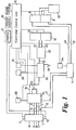
- Fig. 1 is a block diagram of the control system of an inflatable pressure-alternating mattress of the invention.
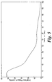
- Figs. 2 and 3 are graphs plotting the cell pressure against time, respectively for alternating-pressure mattresses of Fig. 1 and of the prior art.
- Figs. 4 and 5 are graphs plotting the interface pressure against time, respectively for alternating-pressure mattresses of Fig. 1 and of the prior art.
- the level of interface pressure which will occlude the micro-circulation in a healthy individual is likely to be at least 30mmHg, but in a typical patient at risk of pressure sores this is often 10-15mmHg whilst for patients with existing sores and at very high risk this is likely to be less than 5mmHg. At these very low interface pressures the rate of reduction of pressure is low, and therefore the stimulation of the micro-circulation is greatly reduced if present at all.
- the apparatus shown in Fig. 1 achieves rapid removal of interface pressure at the lower end of the pressure curve. This is achieved by connecting the deflating cell or cells to pressure which is below atmospheric pressure, by the use of one or more air pumps which actively provide such sub-atmospheric pressure. However within the invention other suitable means of providing suction, such as a vacuum reservoir, may be employed.
- air lines are shown by bold lines, and the light lines indicate control functions.
- the control system shown is connected by four air lines A, B, C, H seen at the left hand side, to an inflatable mattress of the standard Pegasus Airwave type, which is substantially as shown in GB-A-1 595 417, having a plurality of tubes extending transversely across the mattress and arranged in two layers, with each tube in the upper layer being supported directly above a tube of the lower layer by side formers.
- the side formers are also inflatable elements, and additionally there are inflatable head cells of the mattress.
- the side formers and head cells are kept permanently inflated, during normal operation of the device, by connection to the line H.
- the tubes are 10cm (4 inches) in diameter.
- the transverse alternating-pressure tubes in the mattress are divided into three groups or arrays, which are respectively connected to the lines A, B and C. Each of these arrays is cyclically inflated and deflated, in a cycle which includes a period in which the tubes of the array are maintained fully inflated and a period in which they are deflated. The total cycle duration is 8 minutes.
- the cycles of the three arrays are out of phase, so that at any time a patient lying on the mattress is supported by two of the arrays which are fully inflated or nearly so, while the third array is deflated so as to withdraw pressure from parts of the patient's body.
- Each tube of the upper layer is in the same array or group as the tube below it in the lower layer, so that these two tubes are inflated and deflated simultaneously.
- the air lines A, B, C, H are connected by a connector device 1 to five air lines 2, 3, 4, 5, 6.
- This connector device 1 is shown and described fully in our co-pending UK Patent Application No. 9716903.1 and corresponding European Patent Application No. 97306046.0, to which reference should be made. It is disconnectable into two parts, to allow the mattress with the air lines A, B, C, H to be removed from the control system. Through relative rotation of two portions of one of these parts, the operator can select one of three functional positions of the connector 1. In a first position, the connector can be separated into its two parts, and in this position, the lines A, B, C, H are all closed at the connector, so that the mattress can be removed without deflation.
- the connector In the other two positions, the connector cannot be separated into its two parts. In a first one of these positions, normal operation with cycling of the cells through their predetermined sequences takes place, the lines A, B, C, H being directly connected through the connector 1 to the respectively lines 3, 4, 5, 6. In the third position, known as the CPR position (cardio-pulmonary resuscitation position), all four of the lines A, B, C, H are connected both to a direct vent to atmosphere through the connector 1, this venting route having a one-way valve, and also to the suction line 2 which leads by a manifold 7 to two air pumps 8, 9 to be described later.
- CPR position cardio-pulmonary resuscitation position
- the connector 1 unlike the connector shown in our UK Patent Application No. 9716903.1 mentioned above has two optical sensors 10, 11, which detect which of the three positions it is in, and provide output signals so that the connector position can be displayed visually on the display 12 of the device, under control of the electronic control unit (ECU) 13.
- ECU electronice control unit
- the air lines 3, 4, 5, 6 are connected to ports of a rotary valve 14 which contains a stator and a rotor, the rotor being driven by a motor 15 which is controlled by the ECU 13.
- This rotary valve 14 also has ports connected to a fill line 16 and an exhaust line 17.
- the stator and rotor contain internal air passages connected to all of these ports, which are connected and disconnected to each other by the continuous rotation of the rotor in order to provide the desired control of the inflation and deflation of the cells of the mattress.
- the fill line 16 is connected at all times during normal operation of the mattress to the air line 6, so that the side formers and head cells connected to the line H are maintained permanently inflated during normal cycling operation.
- the fill line 16 is connected for predetermined periods in the cycling sequence to the lines 3, 4, 5 so that the respective arrays of cells connected to the lines A, B, C are inflated and maintained inflated for the desired periods.
- the rotary valve 14 connects the lines 3, 4, 5 to the exhaust line 17.
- the compressed air for the filling of the mattress is provided by two fill compressors 18, 19 which are also controlled by the ECU 13, and which in this embodiment are operated in tandem, i.e. both are on together or both off together.
- Their output lines 20, 21 are connected by a silencing and buffer chamber 22 and line 23 to a manifold 24 which has an output connected to the fill line 16.
- the manifold 24 also has an overpressure release safety valve 25 which opens to release air to the atmosphere at a predetermined overpressure, higher than the normal operating pressure of the tubes of the mattress.
- a low pressure sensor 26 and a high pressure sensor 27, which provide outputs to the ECU 13.
- Sensor 26 operates when the pressure drops below a predetermined value and the sensor 27 when the pressure reaches a higher predetermined value.
- the ECU 13 controls the operation of the compressors 18, 19 to maintain the pressure in the manifold 24 between these two values.
- an overpressure sensor 28 which senses the pressure in the cell group or groups which are in the inflated phase. In this embodiment this operates at a predetermined pressure higher than that of the sensor 27, to provide an output signal when the pressure exceeds this level. On detection of this output signal, the ECU 13 gives a visual indication on display 12 that the mattress system is adjusting to the patient's weight. Overpressure may occur in the tubes of the mattress, when a patient is placed on the previously inflated mattress.
- the ECU 13 has a mains power input 29, and is connected to the display 12 to indicate the operational state and provide other useful visual signals, and may optionally also be connectable to a remote control 30, for example by a cable or by infrared signalling.
- the ECU 13 contains a microprocessor, programmed to perform the desired control functions. The design and operation of the ECU 13 is conventional for one skilled in the art and need not be described here.
- the exhaust line 17 is connected to the manifold 7, which itself is connected by two vacuum lines 31, 32 to the respective air pumps 8, 9 which when operating provide a sub-atmospheric pressure in the manifold 7.
- the outputs from the pumps 8, 9 pass through a silencing chamber 33 to atmosphere.
- These two pumps 8,9 also operate in tandem, under control of the ECU 13.
- In the manifold 7 there is a chamber connecting both lines 31, 32 to the two lines 2, 17.
- the lines A, B, C are connected via the connector 1 and the rotary valve 14 in turn to the exhaust line 17, for the sequential deflation of the respective tube arrays.
- the passage of air from the deflating cells to the atmosphere occurs as a result of the initial overpressure in the cells relative to atmosphere by the suction or vacuum extraction caused by the operation of the compressors 8, 9.
- the characteristic pressure-reduction curves are shown by Figs. 2 and 4, and are discussed more below.
- the manifold 7 is connected to a vacuum sensor 34 which provides an output signal to the ECU 13 when it senses that a predetermined pressure below atmospheric pressure is reached in the manifold 7. The ECU 13 then switches off the pumps 8, 9.
- the pressure in the manifold 7 is not identical to the pressure in the tube array being deflated, but it has been found possible by trial and error to set a suitable switching level of the compressors 8, 9 so that extraction of air from the tubes stops at a level of pressure within the tubes of the mattress which is significantly below atmospheric pressure but not more than 5mmHg below atmospheric pressure.
- the fill compressors 18, 19 and the air pumps 8, 9 are small linear motor reciprocating compressors or pumps, and may all be identical. Preferably each pair is mounted on a support base so that their moving pistons reciprocate 180° out of phase, minimizing vibration.
- Suitable compressors are those shown in WO 94/28306, WO 94/28308 and WO 96/18037. These compressors have valves which seal the air passages when the compressors are not operating, so that there is no loss of air through the compressors 18, 19 when they are not operating, and no back leakage of air from atmosphere through the pumps 8, 9 when they are not operating. In the event of power failure, therefore, the mattress remains as it is, i.e. deflation is prevented.
- the mattress has air conduits extending longitudinally along it, and connected to the tubes of the respective tube arrays.
- the air lines A, B, C are connected to these longitudinal air conduits at the middle region of the mattress, so that the tubes at the centre of the mattress tend to be inflated and deflated before the tubes at the respective ends of the mattress.
- the lines A, B, C are connected to these longitudinal conduits at one end of the mattress. A patient lying on the mattress may experience slightly different sensations with these two arrangements, as each array inflates and deflates.
- Figs. 2 and 3 respectively show cell (tube) internal pressure curves obtained experimentally for the embodiment of the invention described above in which the standard Pegasus Airwave mattress is operated by the control system shown in Fig. 1, and for the standard Pegasus Airwave mattress in which the arrays of mattress tubes are vented to atmosphere only by the rotary valve during the normal cycling operation of the tubes of the mattress.
- the pressures within the mattress tubes were measured by attaching a conventional pressure-sensing device to the respective tubes.
- a standardised dummy patient weighing 83 kg was lying on the mattress.
- Fig. 3 shows the cycling of the three tube arrays, identified here as A, B and C, respectively connected to the air lines A, B and C, and also the continuously maintained high pressure of the head cells and side formers attached to the line H.
- Each tube array is maintained inflated for a time period which is about twice as long as its deflation phase.
- the pressure drop rate decreases significantly below 10mmHg, and 0mmHg is only slowly approached.
- the sensitivity of measurement does not allow detection of whether or not a true pressure of 0mmHg was actually achieved, but it is clearly impossible in such a system for a pressure lower than 0mmHg to be obtained.
- the pressure curves of Fig. 2 show that, on initiation of deflation of each cell array, there is initially a rapid pressure fall, similar to that of Fig. 3, but that this relatively rapid fall continues with only a slight rate reduction until 0mmHg is obtained, and that a sub-atmospheric pressure is maintained within the tubes for a significant period of time. More precise measurements have shown that in the curves of Fig. 2, the internal pressure of the cells drops from 20mmHg to 0mmHg in about 15 seconds, and drops from 10mmHg to 0mmHg in much less than 10 seconds.
- Figs. 4 and 5 show interface pressures between the mattress and a human patient lying on it, plotted against time, for a mattress using the control system of Fig. 1 and for the standard Pegasus Airwave system. These pressure curves have been measured using a Numotech pressure-mapping device, made by Jasco Products Inc. of Sun Valley, California, USA. This device is a thin sheet containing a very large number of pressure sensors which are arranged in a rectangular array and are interrogated by data processing techniques to provide a pressure map.
- Figs. 4 and 5 show the deflation curve only.
- Fig. 4 shows that with the Airwave mattress connected to the control device of Fig.
- interface pressures of 0mmHg are achieved and that, where the patient has, during the inflated phase of a tube array, an interface pressure of above 20mmHg, for example 50mmHg, in the deflation phase the interface pressure falls from 20mmHg to 5mmHg in less than 10 seconds.
- an interface pressure of above 20mmHg for example 50mmHg
- the pressure fall rate below 20mmHg is reduced. Below 10mmHg it is slow.
- Fig. 1 The control system of Fig. 1, in which the deflation means (pumps 8, 9) are controllable independently of the inflation means (compressors 18, 19) allows two further useful modes of operation of the mattress system.
- the control unit On initial inflation of the mattress, in preparation for its use, all of the mattress cells (tubes) being at first deflated, the control unit (ECU 13) operates the compressors 18, 19 and the rotary valve 14 but suppresses operation of the pumps 8, 9. After all cells have become inflated, by their connection via the rotary valve 14 to the compressors 18, 19, the control means 13 switches itself to the normal cycling mode in which the pumps 8, 9 operate to deflate each group of cells in turn. In this way, the mattress can be made ready for use as quickly as possible, since no air loss occurs during this initiation mode.
- an operator can select a "static mode” by pressing a control button on the ECU 13. This is done when it is desired that the normal inflation/deflation cycling stops but the mattress remains inflated, which is convenient for certain aspects of patient care.
- this "static mode” is selected, the ECU 13 continues operation of the compressors 18, 19 and the rotary valve 14 but stops operation of the extraction pumps 8, 9. Consequently any uninflated cells become inflated but no cells are deflated, and the mattress soon becomes fully inflated and remains so, since the cell groups are cyclically connected to the operating compressors 18, 19.
- the ECU 13 is programmed to permit this "static mode" to continue for at most a predetermined period, in this embodiment 30 minutes.
Abstract
Description
Claims (30)
- A method of operating an inflatable body support having a plurality of inflatable cells, comprising inflating and deflating said cells cyclically in a predetermined sequence, characterised in that said cells are deflated in the predetermined cyclical sequence in such a manner that the interior pressure falls from 10mmHg (135Pa) to 0mmHg in a time period of not more than 15s.
- A method according to claim 1, wherein said time period is not more than 10s.
- A method according to claim 1 or 2, wherein in said predetermined cyclical sequence said cells are deflated in such a manner that their interior pressure falls from 20mmHg (270Pa) to 0mmHg in not more than 30s.
- A method according to claim 3, wherein in said predetermined cyclical sequence said cells are deflated in such a manner that their interior pressure falls from 20mmHg (270Pa) to 0mmHg in not more than 20s.
- A method of operating an inflatable body support having a plurality of inflatable cells, comprising inflating and deflating said cells cyclically in a predetermined sequence, characterised in that said cells are deflated in the predetermined cyclical sequence in such a manner that the interior pressure falls from 20mmHg (270Pa) to 0mmHg (0Pa) in a time period of not more than 30s.
- A method according to claim 5, wherein said time period is not more than 20s.
- A method according to any one of claims 1 to 6, wherein said cells are deflated in said cyclical sequence to a pressure which is less than ambient atmospheric pressure.
- A method according to claim 7, wherein the lowest interior pressure of said cells in said cyclical sequence is in the range 0mmHg to 10mmHg (135Pa) (preferably 0mmHg to 5mmHg) below ambient atmospheric pressure.
- A method according to any one of claims 1 to 8, wherein said cells are deflated in said cyclical sequence by pumping gas from them by means of at least one vacuum pump.
- An inflatable body support havinga plurality of inflatable cells,inflation means (18,19) for inflating said cells,suction means (8,9) for deflating said cells,control means (1,13,14) for causing said cells to be connected to said inflation means and said suction means cyclically in a predetermined cyclical sequence so that said cells are inflated and deflated,said suction means (8,9) being adapted to reduce pressure in said cells when connected thereto in said predetermined cyclical sequence at a rate such that the interior pressure in said cells falls from 10mmHg (135Pa) to 0mmHg in not more than 15s.
- An inflatable body support havinga plurality of inflatable cells,inflation means (18,19) for inflating said cells,suction means (8,9) for deflating said cells,control means (1,13,14) for causing said cells to be connected to said inflation means and said suction means cyclically in a predetermined cyclical sequence so that said cells are inflated and deflated,said suction means (8,9) being adapted to reduce pressure in said cells when connected thereto in said predetermined cyclical sequence at a rate such that the interior pressure in said cells falls from 20mmHg (270Pa) to 0mmHg in not more than 30s.
- An inflatable body support according to claim 10 or 11, wherein said inflation means comprises at least one air compressor (18,19) and said suction means comprises at least one air pump (8,9), said air compressor and said air pump being independent of each other.
- An inflatable body support according to claim 10, 11 or 12, wherein said control means (1,13,14) is switchable from its mode in which the cells are cyclically inflated and deflated to a rapid deflation mode in which all said cells are connected to said suction means (8,9) for rapid deflation thereby.
- An inflatable body support according to any one of claims 10 to 13, wherein said control means (1,13,14) is arranged to effect initial inflation of the cells by suppressing operation of said suction means (8,9) until all said cells are inflated.
- A method of operating an inflatable body support having a patient at least partly supported thereon, which support has a plurality of height-displaceable elements which support said patient and are arranged in groups each group comprising at least one said element, comprising causing said groups of elements to perform cyclic raising and lowering in a predetermined sequence so that said groups sequentially support said patient, characterised in that during said lowering of said elements in said sequence the elements are operated in a manner such that interface pressure exerted between at least some of said elements and said patient falls from 20mmHg (270Pa) to 5mmHg (68Pa) in not more than 15s.
- A method according to claim 15, wherein said interface pressure falls from 20mmHg to 5mmHg in not more than 10s.
- A method according to claim 15 or 16, wherein said interface pressure is reduced to 0mmHg by said lowering of said elements.
- A method according to any one of claims 15 to 17, wherein said height-displaceable elements are upper portions of inflatable cells of flexible material.
- A method according to any one of claims 15 to 18, wherein at least one sheet of flexible material is present between said patient and said height-displaceable elements.
- An inflatable body support having:characterised in that said inflation and deflation means (8,9,18,19) are adapted and arranged for effecting deflation of each of a set of said cells, which is at least some of said plurality of cells, in a manner causing lowering of said upper portion of the cell at a predetermined rate determined by said inflation and deflation means such that interface pressure exerted between the cell and a human patient lying on said body support falls from 20mmHg (270 Pa) to 5mmHg (68 Pa) in not more than 15s.a plurality of inflatable cells having upper portions which are raised and lowered by inflation and deflation of said cells,inflation and deflation means (8,9,18,19) for inflating and deflating said cells,control means (1,13,14) for causing said cells to be operated by said inflation and deflation means cyclically in a predetermined cyclical sequence so that each said cell is cycled through inflation and deflation,
- An inflatable body support according to claim 20, wherein said control means (1,13,14) causes each said cell of said set of cells to be deflated at said predetermined rate while two said cells adjacent thereto are in a fully inflated state.
- An inflatable body support according to claim 20 or 21, wherein said cells are parallel elongate tubes.
- An inflatable body support according to any one of claims 20 to 22, wherein said predetermined rate is such that said interface pressure falls from 20mmHg (270 Pa) to 5mmHg (68 Pa) in not more than 10s.
- An inflatable body support according to any one of claims 20 to 23, wherein said interface pressure is reduced to zero by said lowering of each cell of said set thereof.
- An inflatable body support according to any one of claims 20 to 24, having at least one sheet of flexible material on said upper portions of said cells.
- A method of operating an inflatable body support having a plurality of inflatable cells, comprising inflating and deflating said cells cyclically in a predetermined sequence, characterised in that said cells are deflated in the predetermined cyclical sequence in such a manner that the interior pressure falls to below 0mmHg (ambient atmospheric pressure).
- A method according to claim 26, wherein the lowest interior pressure of said cells in said cyclical sequence is in the range 0mmHg to 10mmHg (135Pa) below ambient atmospheric pressure.
- An inflatable body support havingcharacterised in that said suction means (8,9) are adapted to establish a pressure lower than ambient atmospheric pressure in said cells and said control means (1,13,14) connect said suction means to said cells for a sufficient time in said predetermined cyclical sequence that a pressure lower than ambient atmospheric pressure is established in said cells.a plurality of inflatable cells,inflation means (18,19) for inflating said cells,suction means (8,9) for deflating said cells,control means (1,13,14) for causing said cells to be connected to said inflation means and said suction means cyclically in a predetermined cyclical sequence so that said cells are inflated and deflated,
- An inflatable body support according to claim 28, having at least one sensor (34) arranged to sense suction pressure applied to said cells by said suction means (8,9), said control means operating to stop application of suction to said cells when a predetermined minimum suction pressure is sensed by said sensor.
- An inflatable body support having a plurality of inflatable cells, inflation means (18,19) for inflating said cells and control means (1,13,14) arranged for controlling inflation of said cells by said inflation means and controlling deflation of said cells, said cells being in a plurality of groups each group having at least one said cell and said control means having a normal operation mode in which it effects cyclical inflation and deflation of each said group in a predetermined cyclical sequence with the sequences for the respective groups being out of phase, characterised in that said control means (1,13,14) further has a second operation mode which is selectable by an operator during said normal operation mode and in which all said groups of cells are maintained inflated by connection to said inflation means and deflation of each said group is suppressed.
Priority Applications (1)
| Application Number | Priority Date | Filing Date | Title |
|---|---|---|---|
| EP04028094A EP1510153A1 (en) | 1996-12-18 | 1997-12-15 | Patient supports and methods of operating them |
Applications Claiming Priority (2)
| Application Number | Priority Date | Filing Date | Title |
|---|---|---|---|
| GB9626014 | 1996-12-18 | ||
| GB9626014A GB2312835B (en) | 1996-12-18 | 1996-12-18 | Patient supports and methods of operating them |
Related Child Applications (1)
| Application Number | Title | Priority Date | Filing Date |
|---|---|---|---|
| EP04028094A Division EP1510153A1 (en) | 1996-12-18 | 1997-12-15 | Patient supports and methods of operating them |
Publications (3)
| Publication Number | Publication Date |
|---|---|
| EP0850580A2 true EP0850580A2 (en) | 1998-07-01 |
| EP0850580A3 EP0850580A3 (en) | 1999-08-25 |
| EP0850580B1 EP0850580B1 (en) | 2004-12-15 |
Family
ID=10804460
Family Applications (2)
| Application Number | Title | Priority Date | Filing Date |
|---|---|---|---|
| EP97310103A Expired - Lifetime EP0850580B1 (en) | 1996-12-18 | 1997-12-15 | Patient supports and methods of operating them |
| EP04028094A Withdrawn EP1510153A1 (en) | 1996-12-18 | 1997-12-15 | Patient supports and methods of operating them |
Family Applications After (1)
| Application Number | Title | Priority Date | Filing Date |
|---|---|---|---|
| EP04028094A Withdrawn EP1510153A1 (en) | 1996-12-18 | 1997-12-15 | Patient supports and methods of operating them |
Country Status (8)
| Country | Link |
|---|---|
| US (2) | US5983428A (en) |
| EP (2) | EP0850580B1 (en) |
| AT (1) | ATE284636T1 (en) |
| AU (1) | AU725610B2 (en) |
| DE (1) | DE69731935T2 (en) |
| ES (1) | ES2235219T3 (en) |
| GB (4) | GB2312835B (en) |
| HK (2) | HK1013770A1 (en) |
Cited By (1)
| Publication number | Priority date | Publication date | Assignee | Title |
|---|---|---|---|---|
| WO2003028611A1 (en) * | 2001-10-02 | 2003-04-10 | Indes Holding B.V. | Method and apparatus for height-adjustment of a support surface |
Families Citing this family (27)
| Publication number | Priority date | Publication date | Assignee | Title |
|---|---|---|---|---|
| GB2312835B (en) * | 1996-12-18 | 1998-08-12 | Pegasus Airwave Ltd | Patient supports and methods of operating them |
| US6327727B1 (en) * | 1998-09-08 | 2001-12-11 | Viktor Bocharnikov | Pheumatic cradle |
| GB9822335D0 (en) | 1998-10-13 | 1998-12-09 | Pegasus Airwave Ltd | Inflatable patient supports |
| DK1339369T3 (en) | 2000-11-07 | 2010-03-29 | Tempur World Llc | Therapeutic mattress assembly |
| US6684433B2 (en) * | 2001-03-07 | 2004-02-03 | Gualtiero G. Giori | Pressure adjustable foam support apparatus |
| US6557937B1 (en) | 2001-04-09 | 2003-05-06 | The Research Foundation Of State University Of New York | Pressure-relieving wheelchair seating apparatus |
| US7201766B2 (en) | 2002-07-03 | 2007-04-10 | Life Support Technologies, Inc. | Methods and apparatus for light therapy |
| US8251057B2 (en) | 2003-06-30 | 2012-08-28 | Life Support Technologies, Inc. | Hyperbaric chamber control and/or monitoring system and methods for using the same |
| US7056097B2 (en) * | 2003-07-30 | 2006-06-06 | Equistar Chemicals L.P. | System and method for monitoring the mechanical condition of a reciprocating compressor |
| EP1740143B1 (en) | 2004-04-30 | 2010-08-25 | Hill-Rom Services, Inc. | Patient support |
| US7761945B2 (en) | 2004-05-28 | 2010-07-27 | Life Support Technologies, Inc. | Apparatus and methods for preventing pressure ulcers in bedfast patients |
| US7260860B2 (en) | 2004-08-04 | 2007-08-28 | Hill-Rom Services, Inc. | Mattress system for a hospital bed |
| GB0500117D0 (en) * | 2005-01-06 | 2005-02-09 | Talley Group Ltd | Pump assembly |
| US8104122B2 (en) * | 2005-12-19 | 2012-01-31 | Hill-Rom Services, Inc. | Patient support having an extendable foot section |
| US8348628B2 (en) * | 2006-08-15 | 2013-01-08 | General Electric Company | System and method for monitoring a reciprocating compressor |
| US7849545B2 (en) | 2006-11-14 | 2010-12-14 | Hill-Rom Industries Sa | Control system for hospital bed mattress |
| FR2917278A1 (en) | 2007-06-18 | 2008-12-19 | Hill Rom Ind S A Sa | MATTRESS-TYPE SUPPORT DEVICE HAVING A HETEROGENEUS INFLATABLE STRUCTURE |
| US7814593B2 (en) * | 2007-10-05 | 2010-10-19 | Mady Attila | Gradient bed |
| US20100325806A1 (en) * | 2007-10-09 | 2010-12-30 | Sealy Technology, Llc | Pressure dispersion support systems |
| FR2922439B1 (en) | 2007-10-18 | 2010-12-10 | Hill Rom Ind Sa | METHOD FOR ALTERNATE INFLATION OF AN INFLATABLE CELL SUPPORT DEVICE AND DEVICE FOR IMPLEMENTING IT |
| FR2949320B1 (en) | 2009-08-31 | 2012-11-16 | Hill Rom Ind Sa | LATERAL TILT DEVICE |
| US9277829B2 (en) | 2011-07-22 | 2016-03-08 | TC13—Pressure Applications LLC | Systems and methods for monitoring and providing therapeutic support for a user |
| US10368796B2 (en) | 2011-07-22 | 2019-08-06 | Tc13-Pressure Applications Llc | Systems and methods for monitoring and providing therapeutic support for a user |
| US9086189B2 (en) | 2012-05-16 | 2015-07-21 | Leggett & Platt Canada Co. | System and method for a pressure signal linearization transfer function |
| GB201402974D0 (en) * | 2014-02-20 | 2014-04-09 | Huntleigh Technology Ltd | Improvements in and relating to cell inflation of a mattress |
| US10856668B2 (en) * | 2017-04-10 | 2020-12-08 | Hill-Rom Services, Inc. | Mattress overlay control system with rotary valves and graphical user interface for percussion and vibration, turn assist and microclimate management |
| AU2022302852A1 (en) * | 2021-06-28 | 2023-12-14 | Arjo IP Holding Aktiebolag | Pneumatic connector assembly, inflatable mattress and patient support apparatus |
Citations (2)
| Publication number | Priority date | Publication date | Assignee | Title |
|---|---|---|---|---|
| DE2117767A1 (en) * | 1971-04-07 | 1972-10-19 | Mannesmann-Handel Wärmedienst GmbH, 4300 Essen | Filling and emptying device for pressure change mattresses |
| US5243723A (en) * | 1992-03-23 | 1993-09-14 | Innovative Medical Systems, Inc. | Multi-chambered sequentially pressurized air mattress with four layers |
Family Cites Families (19)
| Publication number | Priority date | Publication date | Assignee | Title |
|---|---|---|---|---|
| GB959103A (en) * | 1961-05-05 | 1964-05-27 | Talley Surgical Instr Ltd | A seat or bed for supporting the human body |
| GB1595417A (en) * | 1977-03-29 | 1981-08-12 | Welch H G | Beds and mattresses |
| GB1599422A (en) * | 1978-05-30 | 1981-09-30 | Glynwed Group Services Ltd | Inflatable supports |
| DK492184D0 (en) * | 1984-10-15 | 1984-10-15 | Jorn Ophee | ALTERNATIVE PRESSURE MATRIDGE OR CUSHION |
| GB8625492D0 (en) * | 1986-10-24 | 1986-11-26 | Huntleigh Technology Plc | Alternating pressure pad |
| AU615543B2 (en) * | 1988-03-23 | 1991-10-03 | Robert Ferrand | Patient support system |
| AUPN004494A0 (en) | 1994-12-14 | 1995-01-12 | Commonwealth Scientific And Industrial Research Organisation | Fumigation of multiple storages with recirculating gaseous fumigant |
| JPH06502317A (en) * | 1990-11-06 | 1994-03-17 | バイオ クリニック コーポレイション | liquid-filled flotation mattress |
| GB9220498D0 (en) * | 1992-09-29 | 1992-11-11 | Pegasus Airwave Ltd | Cushion |
| EP0686083A1 (en) * | 1993-02-23 | 1995-12-13 | GERMINA SPORT-EQUIPMENT GmbH | Process for making a hollow ski and hollow ski made thereby |
| GB9311385D0 (en) * | 1993-06-02 | 1993-07-21 | Contech Int Ltd | Compressor |
| US5586346A (en) * | 1994-02-15 | 1996-12-24 | Support Systems, International | Method and apparatus for supporting and for supplying therapy to a patient |
| GB9424790D0 (en) * | 1994-12-08 | 1995-02-08 | Pegasus Airwave Ltd | Compressor |
| GB9425664D0 (en) * | 1994-12-20 | 1995-02-22 | Pegasus Airwave Ltd | Chair and attachment therefor |
| US5630238A (en) * | 1995-08-04 | 1997-05-20 | Hill-Rom, Inc. | Bed with a plurality of air therapy devices, having control modules and an electrical communication network |
| US5745942A (en) * | 1995-10-19 | 1998-05-05 | Geomarine Systems, Inc. | Simplified control for lateral rotation therapy mattresses |
| US5685036A (en) * | 1996-02-15 | 1997-11-11 | Geomarine Systems, Inc. | Alternating pressure mattress system and method |
| US5815864A (en) * | 1996-04-02 | 1998-10-06 | Sytron Corporation | Microprocessor controller and method of initializing and controlling low air loss floatation mattress |
| GB2312835B (en) * | 1996-12-18 | 1998-08-12 | Pegasus Airwave Ltd | Patient supports and methods of operating them |
-
1996
- 1996-12-18 GB GB9626014A patent/GB2312835B/en not_active Expired - Fee Related
-
1997
- 1997-05-08 US US08/855,717 patent/US5983428A/en not_active Expired - Fee Related
- 1997-12-15 AT AT97310103T patent/ATE284636T1/en not_active IP Right Cessation
- 1997-12-15 DE DE69731935T patent/DE69731935T2/en not_active Expired - Fee Related
- 1997-12-15 ES ES97310103T patent/ES2235219T3/en not_active Expired - Lifetime
- 1997-12-15 GB GB9726474A patent/GB2320429B/en not_active Expired - Fee Related
- 1997-12-15 GB GB9726472A patent/GB2320427B/en not_active Expired - Fee Related
- 1997-12-15 EP EP97310103A patent/EP0850580B1/en not_active Expired - Lifetime
- 1997-12-15 GB GB9726473A patent/GB2320428B/en not_active Expired - Fee Related
- 1997-12-15 EP EP04028094A patent/EP1510153A1/en not_active Withdrawn
- 1997-12-16 AU AU48378/97A patent/AU725610B2/en not_active Ceased
-
1998
- 1998-12-24 HK HK98115301A patent/HK1013770A1/en not_active IP Right Cessation
- 1998-12-24 HK HK98115302A patent/HK1013768A1/en not_active IP Right Cessation
-
1999
- 1999-11-10 US US09/437,214 patent/US6216300B1/en not_active Expired - Fee Related
Patent Citations (2)
| Publication number | Priority date | Publication date | Assignee | Title |
|---|---|---|---|---|
| DE2117767A1 (en) * | 1971-04-07 | 1972-10-19 | Mannesmann-Handel Wärmedienst GmbH, 4300 Essen | Filling and emptying device for pressure change mattresses |
| US5243723A (en) * | 1992-03-23 | 1993-09-14 | Innovative Medical Systems, Inc. | Multi-chambered sequentially pressurized air mattress with four layers |
Cited By (1)
| Publication number | Priority date | Publication date | Assignee | Title |
|---|---|---|---|---|
| WO2003028611A1 (en) * | 2001-10-02 | 2003-04-10 | Indes Holding B.V. | Method and apparatus for height-adjustment of a support surface |
Also Published As
| Publication number | Publication date |
|---|---|
| GB2320427B (en) | 1999-03-10 |
| EP0850580B1 (en) | 2004-12-15 |
| GB2320428A (en) | 1998-06-24 |
| HK1013768A1 (en) | 1999-09-10 |
| GB9626014D0 (en) | 1997-01-29 |
| GB2312835A (en) | 1997-11-12 |
| HK1013770A1 (en) | 1999-09-10 |
| GB2312835B (en) | 1998-08-12 |
| EP1510153A1 (en) | 2005-03-02 |
| ATE284636T1 (en) | 2005-01-15 |
| US6216300B1 (en) | 2001-04-17 |
| GB9726473D0 (en) | 1998-02-11 |
| GB2320427A (en) | 1998-06-24 |
| AU725610B2 (en) | 2000-10-12 |
| AU4837897A (en) | 1998-06-25 |
| GB2320429B (en) | 1999-03-10 |
| GB2320429A (en) | 1998-06-24 |
| GB2320428B (en) | 1999-03-10 |
| DE69731935D1 (en) | 2005-01-20 |
| US5983428A (en) | 1999-11-16 |
| GB9726474D0 (en) | 1998-02-11 |
| DE69731935T2 (en) | 2006-02-16 |
| ES2235219T3 (en) | 2005-07-01 |
| EP0850580A3 (en) | 1999-08-25 |
| GB9726472D0 (en) | 1998-02-11 |
Similar Documents
| Publication | Publication Date | Title |
|---|---|---|
| EP0850580B1 (en) | Patient supports and methods of operating them | |
| US6789284B2 (en) | Inflatable support | |
| US5701622A (en) | Pulsating operating table cushion | |
| AU621880B2 (en) | Pressure controller | |
| US5963997A (en) | Low air loss patient support system providing active feedback pressure sensing and correction capabilities for use as a bed mattress and a wheelchair seating system | |
| EP1722738B1 (en) | Compression treatment system | |
| JPH03118062A (en) | Alternately pressurized pad | |
| US7716767B2 (en) | Device and method for carefully settling a patient in a defined position | |
| US20010034908A1 (en) | Mattress | |
| US20120030878A1 (en) | Positioning Apparatus For Preventing Decubitus Ulcers | |
| WO2019223896A1 (en) | Anti-decubitus device, anti-decubitus bed, method for manufacturing an anti-decubitus mattress | |
| US20200037779A1 (en) | Area support surface seating system | |
| WO1998036665A9 (en) | Mattress support system | |
| WO1998036665A1 (en) | Mattress support system | |
| CN209630039U (en) | A kind of mattress of pre- counteracting bedsores | |
| GB2561977A (en) | Pump unit for alternating pressure mattress for heel protection |
Legal Events
| Date | Code | Title | Description |
|---|---|---|---|
| PUAI | Public reference made under article 153(3) epc to a published international application that has entered the european phase |
Free format text: ORIGINAL CODE: 0009012 |
|
| AK | Designated contracting states |
Kind code of ref document: A2 Designated state(s): AT BE CH DE DK ES FI FR GB IE IT LI NL PT SE |
|
| AX | Request for extension of the european patent |
Free format text: AL;LT;LV;MK;RO;SI |
|
| PUAL | Search report despatched |
Free format text: ORIGINAL CODE: 0009013 |
|
| AK | Designated contracting states |
Kind code of ref document: A3 Designated state(s): AT BE CH DE DK ES FI FR GB GR IE IT LI LU MC NL PT SE |
|
| AX | Request for extension of the european patent |
Free format text: AL;LT;LV;MK;RO;SI |
|
| RIC1 | Information provided on ipc code assigned before grant |
Free format text: 6A 47C 27/10 A, 6A 61G 7/057 B |
|
| 17P | Request for examination filed |
Effective date: 20000118 |
|
| AKX | Designation fees paid |
Free format text: AT BE CH DE DK ES FI FR GB IE IT LI NL PT SE |
|
| 17Q | First examination report despatched |
Effective date: 20020325 |
|
| GRAP | Despatch of communication of intention to grant a patent |
Free format text: ORIGINAL CODE: EPIDOSNIGR1 |
|
| RAP1 | Party data changed (applicant data changed or rights of an application transferred) |
Owner name: PEGASUS LIMITED |
|
| GRAS | Grant fee paid |
Free format text: ORIGINAL CODE: EPIDOSNIGR3 |
|
| GRAA | (expected) grant |
Free format text: ORIGINAL CODE: 0009210 |
|
| AK | Designated contracting states |
Kind code of ref document: B1 Designated state(s): AT BE CH DE DK ES FI FR GB IE IT LI NL PT SE |
|
| PG25 | Lapsed in a contracting state [announced via postgrant information from national office to epo] |
Ref country code: SE Free format text: LAPSE BECAUSE OF FAILURE TO SUBMIT A TRANSLATION OF THE DESCRIPTION OR TO PAY THE FEE WITHIN THE PRESCRIBED TIME-LIMIT Effective date: 20041215 Ref country code: FI Free format text: LAPSE BECAUSE OF FAILURE TO SUBMIT A TRANSLATION OF THE DESCRIPTION OR TO PAY THE FEE WITHIN THE PRESCRIBED TIME-LIMIT Effective date: 20041215 |
|
| REG | Reference to a national code |
Ref country code: GB Ref legal event code: FG4D Ref country code: CH Ref legal event code: EP |
|
| REG | Reference to a national code |
Ref country code: IE Ref legal event code: FG4D |
|
| REF | Corresponds to: |
Ref document number: 69731935 Country of ref document: DE Date of ref document: 20050120 Kind code of ref document: P |
|
| RBV | Designated contracting states (corrected) |
Designated state(s): AT BE CH DE DK ES FI FR IE IT LI NL PT SE |
|
| PG25 | Lapsed in a contracting state [announced via postgrant information from national office to epo] |
Ref country code: DK Free format text: LAPSE BECAUSE OF FAILURE TO SUBMIT A TRANSLATION OF THE DESCRIPTION OR TO PAY THE FEE WITHIN THE PRESCRIBED TIME-LIMIT Effective date: 20050315 |
|
| REG | Reference to a national code |
Ref country code: ES Ref legal event code: FG2A Ref document number: 2235219 Country of ref document: ES Kind code of ref document: T3 |
|
| PLBI | Opposition filed |
Free format text: ORIGINAL CODE: 0009260 |
|
| PLAX | Notice of opposition and request to file observation + time limit sent |
Free format text: ORIGINAL CODE: EPIDOSNOBS2 |
|
| 26 | Opposition filed |
Opponent name: HUNTLEIGH TECHNOLOGY PLC Effective date: 20050913 |
|
| ET | Fr: translation filed | ||
| NLR1 | Nl: opposition has been filed with the epo |
Opponent name: HUNTLEIGH TECHNOLOGY PLC |
|
| PLAF | Information modified related to communication of a notice of opposition and request to file observations + time limit |
Free format text: ORIGINAL CODE: EPIDOSCOBS2 |
|
| PLBB | Reply of patent proprietor to notice(s) of opposition received |
Free format text: ORIGINAL CODE: EPIDOSNOBS3 |
|
| PGFP | Annual fee paid to national office [announced via postgrant information from national office to epo] |
Ref country code: IT Payment date: 20061231 Year of fee payment: 10 |
|
| PGFP | Annual fee paid to national office [announced via postgrant information from national office to epo] |
Ref country code: ES Payment date: 20070420 Year of fee payment: 10 |
|
| PGFP | Annual fee paid to national office [announced via postgrant information from national office to epo] |
Ref country code: CH Payment date: 20070425 Year of fee payment: 10 Ref country code: AT Payment date: 20070425 Year of fee payment: 10 |
|
| PGFP | Annual fee paid to national office [announced via postgrant information from national office to epo] |
Ref country code: IE Payment date: 20070426 Year of fee payment: 10 |
|
| PGFP | Annual fee paid to national office [announced via postgrant information from national office to epo] |
Ref country code: NL Payment date: 20070430 Year of fee payment: 10 |
|
| PGFP | Annual fee paid to national office [announced via postgrant information from national office to epo] |
Ref country code: DE Payment date: 20070502 Year of fee payment: 10 |
|
| PLBP | Opposition withdrawn |
Free format text: ORIGINAL CODE: 0009264 |
|
| PLBD | Termination of opposition procedure: decision despatched |
Free format text: ORIGINAL CODE: EPIDOSNOPC1 |
|
| PLAM | Termination of opposition procedure: information related to despatch of decision modified |
Free format text: ORIGINAL CODE: EPIDOSCOPC1 |
|
| PLAU | Termination of opposition procedure: information related to despatch of decision deleted |
Free format text: ORIGINAL CODE: EPIDOSDOPC1 |
|
| PLBD | Termination of opposition procedure: decision despatched |
Free format text: ORIGINAL CODE: EPIDOSNOPC1 |
|
| PLBM | Termination of opposition procedure: date of legal effect published |
Free format text: ORIGINAL CODE: 0009276 |
|
| STAA | Information on the status of an ep patent application or granted ep patent |
Free format text: STATUS: OPPOSITION PROCEDURE CLOSED |
|
| PG25 | Lapsed in a contracting state [announced via postgrant information from national office to epo] |
Ref country code: PT Free format text: LAPSE BECAUSE OF NON-PAYMENT OF DUE FEES Effective date: 20050515 |
|
| PGFP | Annual fee paid to national office [announced via postgrant information from national office to epo] |
Ref country code: BE Payment date: 20070427 Year of fee payment: 10 |
|
| 27C | Opposition proceedings terminated |
Effective date: 20070915 |
|
| NLR2 | Nl: decision of opposition |
Effective date: 20070915 |
|
| PGFP | Annual fee paid to national office [announced via postgrant information from national office to epo] |
Ref country code: FR Payment date: 20070425 Year of fee payment: 10 |
|
| BERE | Be: lapsed |
Owner name: *PEGASUS LTD Effective date: 20071231 |
|
| REG | Reference to a national code |
Ref country code: CH Ref legal event code: PL |
|
| PG25 | Lapsed in a contracting state [announced via postgrant information from national office to epo] |
Ref country code: AT Free format text: LAPSE BECAUSE OF NON-PAYMENT OF DUE FEES Effective date: 20071215 |
|
| NLV4 | Nl: lapsed or anulled due to non-payment of the annual fee |
Effective date: 20080701 |
|
| REG | Reference to a national code |
Ref country code: IE Ref legal event code: MM4A |
|
| PG25 | Lapsed in a contracting state [announced via postgrant information from national office to epo] |
Ref country code: BE Free format text: LAPSE BECAUSE OF NON-PAYMENT OF DUE FEES Effective date: 20071231 |
|
| PG25 | Lapsed in a contracting state [announced via postgrant information from national office to epo] |
Ref country code: LI Free format text: LAPSE BECAUSE OF NON-PAYMENT OF DUE FEES Effective date: 20071231 Ref country code: IE Free format text: LAPSE BECAUSE OF NON-PAYMENT OF DUE FEES Effective date: 20071217 Ref country code: DE Free format text: LAPSE BECAUSE OF NON-PAYMENT OF DUE FEES Effective date: 20080701 Ref country code: CH Free format text: LAPSE BECAUSE OF NON-PAYMENT OF DUE FEES Effective date: 20071231 |
|
| REG | Reference to a national code |
Ref country code: FR Ref legal event code: ST Effective date: 20081020 |
|
| PG25 | Lapsed in a contracting state [announced via postgrant information from national office to epo] |
Ref country code: NL Free format text: LAPSE BECAUSE OF NON-PAYMENT OF DUE FEES Effective date: 20080701 |
|
| REG | Reference to a national code |
Ref country code: ES Ref legal event code: FD2A Effective date: 20071217 |
|
| PG25 | Lapsed in a contracting state [announced via postgrant information from national office to epo] |
Ref country code: FR Free format text: LAPSE BECAUSE OF NON-PAYMENT OF DUE FEES Effective date: 20071231 Ref country code: ES Free format text: LAPSE BECAUSE OF NON-PAYMENT OF DUE FEES Effective date: 20071217 |
|
| PG25 | Lapsed in a contracting state [announced via postgrant information from national office to epo] |
Ref country code: IT Free format text: LAPSE BECAUSE OF NON-PAYMENT OF DUE FEES Effective date: 20071215 |