EP0850412B1 - Electrophoretic system including means for replacing separation medium - Google Patents
Electrophoretic system including means for replacing separation medium Download PDFInfo
- Publication number
- EP0850412B1 EP0850412B1 EP96928167A EP96928167A EP0850412B1 EP 0850412 B1 EP0850412 B1 EP 0850412B1 EP 96928167 A EP96928167 A EP 96928167A EP 96928167 A EP96928167 A EP 96928167A EP 0850412 B1 EP0850412 B1 EP 0850412B1
- Authority
- EP
- European Patent Office
- Prior art keywords
- capillary
- gel
- electrophoretic
- capillaries
- separation medium
- Prior art date
- Legal status (The legal status is an assumption and is not a legal conclusion. Google has not performed a legal analysis and makes no representation as to the accuracy of the status listed.)
- Expired - Lifetime
Links
- 238000000926 separation method Methods 0.000 title claims description 62
- 238000010926 purge Methods 0.000 claims description 22
- 238000001962 electrophoresis Methods 0.000 claims description 14
- 239000007853 buffer solution Substances 0.000 claims 1
- 238000012544 monitoring process Methods 0.000 claims 1
- 239000000499 gel Substances 0.000 description 128
- 238000000034 method Methods 0.000 description 19
- 230000008569 process Effects 0.000 description 15
- 239000000872 buffer Substances 0.000 description 14
- 239000002699 waste material Substances 0.000 description 14
- 229920002401 polyacrylamide Polymers 0.000 description 5
- 238000005251 capillar electrophoresis Methods 0.000 description 4
- 238000007906 compression Methods 0.000 description 4
- 230000006835 compression Effects 0.000 description 4
- 230000005684 electric field Effects 0.000 description 3
- 239000002184 metal Substances 0.000 description 3
- 238000007789 sealing Methods 0.000 description 3
- 238000001712 DNA sequencing Methods 0.000 description 2
- 239000011248 coating agent Substances 0.000 description 2
- 238000000576 coating method Methods 0.000 description 2
- 230000000295 complement effect Effects 0.000 description 2
- 239000004020 conductor Substances 0.000 description 2
- 238000001514 detection method Methods 0.000 description 2
- 230000000694 effects Effects 0.000 description 2
- 238000002347 injection Methods 0.000 description 2
- 239000007924 injection Substances 0.000 description 2
- 239000000463 material Substances 0.000 description 2
- 239000011159 matrix material Substances 0.000 description 2
- 230000005012 migration Effects 0.000 description 2
- 238000013508 migration Methods 0.000 description 2
- 239000000203 mixture Substances 0.000 description 2
- 108091034117 Oligonucleotide Proteins 0.000 description 1
- 239000004809 Teflon Substances 0.000 description 1
- 229920006362 Teflon® Polymers 0.000 description 1
- JLCPHMBAVCMARE-UHFFFAOYSA-N [3-[[3-[[3-[[3-[[3-[[3-[[3-[[3-[[3-[[3-[[3-[[5-(2-amino-6-oxo-1H-purin-9-yl)-3-[[3-[[3-[[3-[[3-[[3-[[5-(2-amino-6-oxo-1H-purin-9-yl)-3-[[5-(2-amino-6-oxo-1H-purin-9-yl)-3-hydroxyoxolan-2-yl]methoxy-hydroxyphosphoryl]oxyoxolan-2-yl]methoxy-hydroxyphosphoryl]oxy-5-(5-methyl-2,4-dioxopyrimidin-1-yl)oxolan-2-yl]methoxy-hydroxyphosphoryl]oxy-5-(6-aminopurin-9-yl)oxolan-2-yl]methoxy-hydroxyphosphoryl]oxy-5-(6-aminopurin-9-yl)oxolan-2-yl]methoxy-hydroxyphosphoryl]oxy-5-(6-aminopurin-9-yl)oxolan-2-yl]methoxy-hydroxyphosphoryl]oxy-5-(6-aminopurin-9-yl)oxolan-2-yl]methoxy-hydroxyphosphoryl]oxyoxolan-2-yl]methoxy-hydroxyphosphoryl]oxy-5-(5-methyl-2,4-dioxopyrimidin-1-yl)oxolan-2-yl]methoxy-hydroxyphosphoryl]oxy-5-(4-amino-2-oxopyrimidin-1-yl)oxolan-2-yl]methoxy-hydroxyphosphoryl]oxy-5-(5-methyl-2,4-dioxopyrimidin-1-yl)oxolan-2-yl]methoxy-hydroxyphosphoryl]oxy-5-(5-methyl-2,4-dioxopyrimidin-1-yl)oxolan-2-yl]methoxy-hydroxyphosphoryl]oxy-5-(6-aminopurin-9-yl)oxolan-2-yl]methoxy-hydroxyphosphoryl]oxy-5-(6-aminopurin-9-yl)oxolan-2-yl]methoxy-hydroxyphosphoryl]oxy-5-(4-amino-2-oxopyrimidin-1-yl)oxolan-2-yl]methoxy-hydroxyphosphoryl]oxy-5-(4-amino-2-oxopyrimidin-1-yl)oxolan-2-yl]methoxy-hydroxyphosphoryl]oxy-5-(4-amino-2-oxopyrimidin-1-yl)oxolan-2-yl]methoxy-hydroxyphosphoryl]oxy-5-(6-aminopurin-9-yl)oxolan-2-yl]methoxy-hydroxyphosphoryl]oxy-5-(4-amino-2-oxopyrimidin-1-yl)oxolan-2-yl]methyl [5-(6-aminopurin-9-yl)-2-(hydroxymethyl)oxolan-3-yl] hydrogen phosphate Polymers Cc1cn(C2CC(OP(O)(=O)OCC3OC(CC3OP(O)(=O)OCC3OC(CC3O)n3cnc4c3nc(N)[nH]c4=O)n3cnc4c3nc(N)[nH]c4=O)C(COP(O)(=O)OC3CC(OC3COP(O)(=O)OC3CC(OC3COP(O)(=O)OC3CC(OC3COP(O)(=O)OC3CC(OC3COP(O)(=O)OC3CC(OC3COP(O)(=O)OC3CC(OC3COP(O)(=O)OC3CC(OC3COP(O)(=O)OC3CC(OC3COP(O)(=O)OC3CC(OC3COP(O)(=O)OC3CC(OC3COP(O)(=O)OC3CC(OC3COP(O)(=O)OC3CC(OC3COP(O)(=O)OC3CC(OC3COP(O)(=O)OC3CC(OC3COP(O)(=O)OC3CC(OC3COP(O)(=O)OC3CC(OC3COP(O)(=O)OC3CC(OC3CO)n3cnc4c(N)ncnc34)n3ccc(N)nc3=O)n3cnc4c(N)ncnc34)n3ccc(N)nc3=O)n3ccc(N)nc3=O)n3ccc(N)nc3=O)n3cnc4c(N)ncnc34)n3cnc4c(N)ncnc34)n3cc(C)c(=O)[nH]c3=O)n3cc(C)c(=O)[nH]c3=O)n3ccc(N)nc3=O)n3cc(C)c(=O)[nH]c3=O)n3cnc4c3nc(N)[nH]c4=O)n3cnc4c(N)ncnc34)n3cnc4c(N)ncnc34)n3cnc4c(N)ncnc34)n3cnc4c(N)ncnc34)O2)c(=O)[nH]c1=O JLCPHMBAVCMARE-UHFFFAOYSA-N 0.000 description 1
- 238000013459 approach Methods 0.000 description 1
- 238000006243 chemical reaction Methods 0.000 description 1
- 238000010276 construction Methods 0.000 description 1
- 239000003792 electrolyte Substances 0.000 description 1
- 238000005429 filling process Methods 0.000 description 1
- 238000009472 formulation Methods 0.000 description 1
- 239000011521 glass Substances 0.000 description 1
- 238000009434 installation Methods 0.000 description 1
- 230000007246 mechanism Effects 0.000 description 1
- 238000012986 modification Methods 0.000 description 1
- 230000004048 modification Effects 0.000 description 1
- 229920003023 plastic Polymers 0.000 description 1
- 239000004033 plastic Substances 0.000 description 1
- 238000005086 pumping Methods 0.000 description 1
- 238000011160 research Methods 0.000 description 1
Images





Classifications
-
- G—PHYSICS
- G01—MEASURING; TESTING
- G01N—INVESTIGATING OR ANALYSING MATERIALS BY DETERMINING THEIR CHEMICAL OR PHYSICAL PROPERTIES
- G01N27/00—Investigating or analysing materials by the use of electric, electrochemical, or magnetic means
- G01N27/26—Investigating or analysing materials by the use of electric, electrochemical, or magnetic means by investigating electrochemical variables; by using electrolysis or electrophoresis
- G01N27/416—Systems
- G01N27/447—Systems using electrophoresis
- G01N27/44704—Details; Accessories
-
- G—PHYSICS
- G01—MEASURING; TESTING
- G01N—INVESTIGATING OR ANALYSING MATERIALS BY DETERMINING THEIR CHEMICAL OR PHYSICAL PROPERTIES
- G01N27/00—Investigating or analysing materials by the use of electric, electrochemical, or magnetic means
- G01N27/26—Investigating or analysing materials by the use of electric, electrochemical, or magnetic means by investigating electrochemical variables; by using electrolysis or electrophoresis
- G01N27/416—Systems
- G01N27/447—Systems using electrophoresis
- G01N27/44756—Apparatus specially adapted therefor
- G01N27/44782—Apparatus specially adapted therefor of a plurality of samples
Definitions
- This invention relates in general to capillary electrophoresis and, in particular, to a capillary electrophoretic system with means for replacing separation medium in a capillary.
- connection of the syringe to the capillary tube was made using either a Teflon sheath or a custom-made tapered glass syringe as described by Sudor et al. The connection was made by hand and had to be made and broken once for each gel replacement. The capillary tube is effectively removed from the electrophoresis circuit during the resealing process.
- the replaceable gel currently being produced and used requires 700-1,300 psi pressure to be driven through the capillary tubes with internal diameters of 75-100 microns in a 5-15 minute refill period.
- This pressure range is far above that which is compatible with easily made and broken seals such as that usually used in capillary electrophoretic systems. Because of this and other factors described above, it is difficult to automate the gel replacement process using conventional or other electrophoretic systems that have been proposed. It is therefore desirable to provide an improved electrophoretic system which avoids the above drawbacks.
- the invention as defined by the claims permits deliver of a viscous separation medium to one or more capillaries, so that in a first setting of valve means, the delivery of new viscous separation medium clears the conduit means of old viscous separation medium, and in a second setting of the valve means, the delivery of new viscous separation medium clears old viscous separation medium from and delivers new viscous separation medium to said one or more capillaries.
- Another application of the invention is directed towards a method for delivering a viscous separation medium to one or more capillaries employing conduit means for supplying viscous separation medium to said one or more capillaries, comprising the steps of delivering new viscous separation medium to displace old viscous separation medium in the conduit means, and delivering new viscous separation medium to said one or more capillaries through said conduit means.
- the invention is used in an apparatus for electrophoretic separation, comprising medium conduit means; at least one separation capillary having an inlet and an outlet; and control means connecting the outlet of the at least one capillary to the medium conduit means, so that viscous separation medium is injectable from the medium conduit means to the at least one capillary to displace old viscous separation medium in the at least one capillary, and application of an electrical potential across the at least one capillary inlet and the medium conduit means will cause electrophoretic separation of a sample in the at least one capillary.
- the invention enables a method for electrophoretic separation, comprising the steps of sealingly connecting an outlet of at least one separation capillary having an outlet to medium conduit means to form sealed connections there between so that a predetermined pressure greater than atmospheric pressure can be maintained in the at least one capillary; injecting viscous separation medium into the at least one capillary to purge the at least one capillary of old viscous separation medium, if any, in the at least one capillary by means of the medium conduit means; and applying an electrical field in the at least one capillary to separate any samples present in the at least one capillary.
- the injecting and applying steps are performed without breaking the sealed connections
- the invention is useful in an apparatus for use in an electrophoretic device, comprising a housing defining a chamber therein for housing an end of at least one capillary, a first conduit to said chamber for passage of said at least one capillary, and at least an additional conduit for passage of an electrode means and for injection of viscous separation medium into the chamber in order to displace old viscous separation medium, if any, in the at least one capillary.
- the invention enables a method for electrophoretic separation, comprising the steps of providing a housing defining a chamber therein for housing an end of at least one capillary, a first conduit to said chamber for passage of said at least one capillary, and at least an additional conduit for passage of an electrode and for injection of viscous separation medium into the chamber in order to displace old viscous separation medium, if any, in the at least one capillary.
- the method further comprises the steps of injecting viscous separation medium into the chamber to purge the chamber and the at least one capillary to purge the chamber and the at least one capillary of old viscous separation medium, if any, by means of the at least one additional conduit; connecting an electrode to said at least one additional conduit; and applying an electrical potential between the electrode and the viscous separation medium in the at least one - capillary to cause separation of any sample in the at least one capillary.
- the viscous separation medium is a gel.
- the invention is described below by reference to gel as the separation medium.
- Fig. 1 is a schematic view of a system for displacing old gel in the capillaries with new gel to illustrate the invention.
- System 10 of Fig. 1 includes two manifolds 12 and 14.
- Manifold 12 is used for injecting new gel into one or more capillaries 16 to displace the old gel in these capillaries by new gel.
- manifold 14 is used for injecting new gel into one or more capillaries 18 to displace the old gel therein.
- Manifolds 12 and 14 are connected by gel delivery lines to a three-way valve 20.
- Valve 20 is in turn connected to a waste line 22 so that the gel waste passing through the valve and line 22 may be deposited into a gel waste container 24.
- Valve 20 is controlled by motor 26 in order to connect one of the two manifolds 12 and 14 with waste line 22.
- Manifolds 12 and 14 are connected by delivery lines to a gel pump 30 through a back press regulator 32.
- a pressure sensor 34 senses the pressure in the delivery line 36 connecting the pump and the regulator.
- Manifolds 12 and 14 are used in each filling process for displacing the gel in the one or more capillaries 16, 18. Therefore, when system 10 is used to deliver new gel to the capillaries 16, 18, the manifolds may contain gel which was left over from the prior delivering process so that it is desirable to purge the manifolds of the old gel.
- motor 26 operates valve 20 to connect manifold 12 to waste line 22.
- Pump 30 is then operated by the stepper motor 38 to deliver a predetermined amount of gel in order to purge manifold 12 of the old gel therein. This would then fill manifold 12 with new gel and would greatly reduce the chances that the old gel originally present in manifold 12 would contaminate the new gel delivered by the pump to the one or more capillaries 16.
- waste line 42 connecting manifold 12 and valve 20 as well as waste line 22 are much larger in dimensions than the inner diameters of the one or more capillaries 16, so that most of the gel delivered by the pump would flow through manifold 12, line 42, valve 20, and line 22 to container 24, instead of to the one or more capillaries 16.
- motor 26 is used to control valve 20 so as to disconnect line 22 from line 42 and instead connect it to line 44 leading to manifold 14.
- Pump 30 again delivers new gel in order to purge manifold 14 of the old gel through line 44, valve 20 and line 22.
- motor 26 is used to disconnect line 22 from lines 42 and 44.
- Pump 30 is then controlled by stepper motor 38 to deliver gel to line 36.
- the pressure in line 36 is sensed by pressure sensor 34 so that a high pressure in line 36 (such as 1200 psi) is maintained during the delivery.
- a high pressure in line 36 such as 1200 psi
- approximately three capillary volumes of gel is delivered through each of the capillaries 16, 18.
- valve 20 then causes valve 20 to connect lines 42, 44 to line 22 and pump 30 may then be reversed to depressurize the system.
- the back pressure regulator 32 closes when the high pressure in the manifolds, 12, 14, the capillaries, lines 42, 44, 22 and lines connecting the regulator to manifolds 12, 14 are released and vented to the atmosphere.
- System 10 is advantageous in that it completely automates the process of filling the capillaries with new gel. No gas pressure is used and the system lends itself to microprocessor automated control. The system permits delivery of a pre-set volume of gel at a pre-set head pressure.
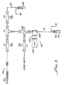
- Fig. 2 is a schematic view of an electrophoretic system 100 which permits gel in the one or more separation capillaries 16 to be replaced without having to frequently make and break a high pressure seal to the capillary adequate for the gel replacement process.
- fresh gel may be injected into the one or more capillaries 16 through their outlet ends by means of a gel-filled syringe 102.
- the outlet end or ends (not shown) of the one or more capillaries 16 may be connected to and sealed in a chamber in housing U1.
- the stale or old gel in the one or more capillaries would emerge through the inlet end or ends into the inlet buffer reservoir 104.
- one or more samples to be separated may be introduced into the one or more capillaries through the one or more inlet ends 16a.
- the outlet end or ends of the one or more capillaries 16 are connected electrically to an output buffer 106 by means of an electrolyte in a manner described below.
- a separation electrical potential is then applied across the inlet and outlet buffer reservoirs 104, 106 causing the one or more samples injected to be separated by electrophoresis as the sample components migrate from the one or more inlet ends 16a towards the one or more outlet ends.
- detector 110 which includes a parabolic reflector 110a, filters 110b, and photomultiplier tube 110c.
- a laser is used to induce fluorescence of tagged samples and such fluorescence is then detected by means of reflector 110a which collects the light and filters 110b filters the emission light collected and passes it onto the photomultiplier tube 110c for detection in a manner known to those skilled in the art.
- the laser source is not shown in Fig. 2 .
- a high pressure seal is made directly to the one or more capillaries 16 using a non-conductive high pressure compression fitting. This seal remains in place for the use-life of the capillary column which is determined by the capillary wall coating material and not by the life of the gel.
- This high pressure seal is made to the outlet end or ends of the one or more capillaries 16 after the detector 110 to eliminate volume constraints. Since the valving system for gel replacement is connected to the outlet end of the capillary, the sample components do not reach such valving system until after they have been detected by detector 110. Hence, no electrophoretic resolution losses are encountered regardless of the volumes of the valving system and the associated connecting tubing. This then leaves the inlet end or ends 16a available for interfacing with low volume samples on an automatic sample injector (not shown).
- system 100 is configured for gel replacement.
- valve V1 is open and valve V2 is closed.
- the fresh gel from syringe 102 therefore passes through valve V1, the chamber in T-connector T1, the chamber in connector U1 and from there into the outlet end or ends of the one or more capillaries 16.
- displaced old gel from the one or more capillaries would exit into buffer 104.
- valve V2 is opened and valve V1 remains open, in state two.
- system 100 is configured for pressure relief and purging of the valving system and gel lines.
- valve V2 is open, the high pressure required for the gel replacement process is relieved through the valve V2 and tubing 112.
- Fresh gel delivered by syringe 102 then purges the chamber in T-connector T1 and valve V2 as well as tubing 112 of the old gel.
- device 100 is configured for electrophoresis.
- valve V1 is closed and valve V2 remains open.
- a high electrical potential is applied by a power supply (not shown) between the two buffers 104, 106.
- the electrical circuit is completed through the buffers 104, 106 and the gel medium in the one or more capillaries 16, and the gel medium in the chambers in connector U1, T-connector T1, valve V2, and in tubing 112.
- the electrophoretic current therefore passes from the high voltage electrode at the one or more capillary inlets 16a, buffer 104, through the capillary column(s) and finally through the valving system to the electrically grounded buffer 106.
- the gel-filled syringe 102 contains the prepolymerized polyacrylamide of a formulation suitable for DNA sequencing, for example.
- the syringe is simply mounted in a vice equipped with a force gauge.
- syringe 102 is preferably replaced by a programmable gel delivery system such as that shown in Fig. 1 .
- the syringe is coupled to narrow bore (0.015-0.020 inches internal diameter) FEP or other type tubing using a compression type union.
- syringe 102 is replaced by pump 30, regulator 32, sensor 34, conduit 36 and motor 38 of Fig. 1 , where regulator 32 is connected by a gel delivery line to valve V1.
- sensor 34 is used to sense the pressure in conduit 36.
- Regulator 32 disconnects the pump 30 and conduit 36 from the valving system downstream from and connected to regulator 32 when the system is vented to atmospheric pressure and also when the system is employed to perform electrophoresis as described above. This prevents gel from being injected into the capillaries or the remaining portion of the electrophoretic circuit path between buffers 104, 106 to disturb the electrophoresis process.
- samples injected may migrate into the gel in the valving system during electrophoresis.
- migrated components left in the valving system from prior electrophoretic runs may contaminate the sample in the current run.
- the valving and tubing systems downstream from the outlet or outlets of the one or more capillaries in the electrophoresis migration direction are much larger in dimensions compared to the cross-sectional dimensions of the one or more capillaries, the electric field in the gel medium inside the valving system as well as associated tubing are much lower than that inside the one or more capillaries.
- migration distances are expected to be very small in the valving system. This problem is further addressed in the embodiment illustrated in Figs. 3 and 4 .
- Fig. 3 is a schematic view of an electrophoretic system with means for replacing gel in one or more separation capillaries with fresh gel as in Fig. 2 and further provided with means for purging the valve system of any gas bubbles as well as any sample components from previous electrophoretic runs.
- System 150 differs from system 100 of Fig. 2 in that connector U1 is replaced by a T-shaped T-connector T2 having a chamber t2 therein for housing the outlet end or ends 16b of the one or more capillaries 16 and connected to valve V3 through which waste gel can be disposed of.
- the old gel in T-connector T1 and valve V2 and tubing 112 is first purged before new gel is delivered to the capillaries.
- valve V3 is closed, and the other two valves are open so that the fresh gel delivered by syringe 102 will purge the chambers in V1, T1, V2 of the system 150. Then in order to purge the valving system between T-connector T1 and the capillary tip or tips 16b to eliminate any trapped air or other gas forced into this system from the pumping mechanism, valve V2 is closed and the other two valves are open so that the fresh gel delivered by syringe 102 will purge such part of the valving system through valve V3.
- valve V1 when valve V1 is open and valves V2, V3 are closed, the fresh gel delivered by syringe 102 (or pump 30, regulator 32, sensor 34, conduit 36, motor 38) is delivered to the one or more capillaries 16 through the outlet ends to displace the old or stale gel therein through the inlet end or ends 16a and into buffer reservoir 104. To relieve the pressure required during the gel replacement process, all three valves are opened.
- Fig. 4 is a schematic view of an electrophoretic system similar in construction to system 150 of Fig. 3 except that T-connector T2 and valve V3 have been eliminated by rearranging the connections between the capillary and valve V2 to T-connector T1 in a manner so that the outlet end or ends 16b of the one or more capillaries 16 extend into and is housed by chamber t1 in T-connector T1 as shown in Fig. 4 .
- both valves V1, V2 are open when gel is delivered.
- valve V1 is open and valve V2 is closed when gel is delivered by syringe 102 (or pump 30, regulator 32, sensor 34, conduit 36, motor 38).
- Fig. 5 is a schematic view of an electrophoretic system 180 which operates in a similar manner as systems 150, 170 of Figs. 1-4 .
- gel is delivered by means of a gel pump 30 where the pressure of the gel delivered is sensed by pressure sensor 34 and a back regulator 32 isolates pump 30 from line 36 when the portion of the system 180 downstream from line 36 is vented to the atmosphere.
- Line 36 is connected to manifold 200 by means of a nut 216 having grooves complementary to those of a hole in the manifold so that the nut can be screwed in the hole.
- Line 36 is threaded through a hole in nut 216 and is sealingly held therein by means of non-conductive high pressure compression fitting. In this manner, high pressure gel can be delivered by pump 30 through line 36 to a chamber within manifold 200.
- the outlet end(s) of one or more capillaries 16' are enclosed within the chamber in the manifold 200 so that the gel delivered through line 36 can be used to displace old gel in the capillary array 16' into reservoir 104.
- electrode fitting 208 can be screwed into a threaded hole in the manifold 200, where the electrode fitting can be used as one terminal for applying electrical potential. Hence, if an electrical potential is applied between buffer 104 and electrode fitting 208, the electric field present in the capillary array 16' may be used for electrophoretic separation.
- one or more samples may be introduced into the capillaries in array 16' through their ends 16'a.
- the separated components may be detected with the aid of reflector 222 and a detector (not shown) in detection window 223. Some of the separated components may migrate into the chamber within manifold 200. To prevent the components from previous runs in such chamber from contaminating the gel to be delivered to the array 16', it will be desirable to purge the chamber within manifold 200 of the old gel prior to another electrophoretic run.
- Electrode fitting 208 has a hole therein through which the old gel in the chamber in manifold 200 may be purged.
- another gel line 214 for disposal of waste gel is connected to such hole in the electrode fitting by means of another nut 216 which is screwed into a complementary hole within electrode fitting 208.
- Line 214 passes through a hole in nut 216 and is sealingly attached thereto by non-conductive high pressure compression fitting.
- a waste valve 212 controls line 214. Therefore, when the old gel within the chamber in manifold 200 is to be purged, waste valve 212 is opened and pump 30 delivers new gel to the chamber in order to purge it of the old gel, which exits through line 214 to waste reservoir 106. After the purging process, valve 212 is closed so that array 16' may then be purged by means of new gel from pump 30 as in systems described above and the system is then ready for another electrophoretic run.
- Fig. 6 is a perspective view of a portion 200 of the electrophoretic system 180 of Fig. 5 including the manifold 202 with portions cut away to illustrate the preferred embodiment of the invention.
- system portion 200 may also be used to replace portion 170' in Fig. 4 .
- the lenses 110b and photomultiplier tube 110c of Fig. 4 are not shown in Fig. 6 , which shows only the parabolic mirror 110a.
- the connection between gel inlet line (similar to line 142 of Fig. 4 ) and the portion 200 also is not shown in Fig. 6 ; such connection is illustrated in Figs. 7 and 8 .
- System portion 200 includes a manifold 202, a portion of which has been cut away to reveal the plurality of capillaries 16', parabolic mirror 110a, array holder 204, chamber 206, and electrode fitting 208.
- the array of capillaries 16' pass through and are held in position by an array holder 204 so that the ends 16a' remain in chamber 206.
- Array holder 204 has a cylindrical portion 204a which fits snugly into chamber 206 and O-ring 210 provides a sealing connection between the array holder and the chamber wall of chamber 206. Such sealing connection can withstand the required pressure of over 400 psi for the gel replacement process described above.
- Parabolic mirror 110a is mounted onto an annular member 222 which may slide along guide 224.
- cylindrical portion 204a of holder 204 is sealingly connected to the chamber wall of chamber 206 as described above, where the holder 204 holds the array of capillaries 16' with ends 16a' inside the chamber.
- annular member 222 is slid along guide 224 in direction 230 to engage the top surface of array holder 204, thereby locking the array holder in place.
- the top plate portion 204b has a wedge-shaped portion 204b' facing member 222 to facilitate the sliding engagement with member 222. Since the annular member 222 can only move along direction 230 or in the opposite direction to 230, array holder 204 will be locked in place until annular member 222 is slid in a direction opposite to 230.
- fitting 208 defines two cylindrical holes 208a, 208b connected by a small hole 208c.
- hole 208a is connected to line 214 through which the old gel from chamber 206 may be purged to a waste container 106 in Fig. 5 .
- Fig. 7 is a perspective view of the system portion 200 of Fig. 6 but from a different angle from the back.
- Fig. 8 is a cross-sectional view of assembly portion 200 along the line 8-8 in Fig. 7 .
- fresh gel may be injected by a syringe or pump (not shown) through a valve and line (not shown) to gel inlet 232 for supplying fresh gel to chamber 206.
- Fig. 9A is a perspective view of electrode fitting 208. As shown in Figs. 8 and 9A , portion 208' and 208" fit snugly (by means of complimentary threads) onto corresponding surfaces of a hole in manifold 202 to withstand the over 400 psi pressure. As more clearly shown in Figs. 5 and 8 , a small hole 237 in the manifold 202 connects hole 208a (and line 214 of Fig. 5 ) through hole 208c to chamber 206.
- Fig. 9B is a top view of fitting 208 and Fig. 9C is a cross-sectional view of the fitting.
- Manifold 202 may be made of a plastic material.
- electrode fitting 208 has rounded surfaces to keep current density low.
- the electrode fitting 208 may be made of low resistance, electrically conductive material.
Landscapes
- Health & Medical Sciences (AREA)
- Life Sciences & Earth Sciences (AREA)
- Molecular Biology (AREA)
- Chemical & Material Sciences (AREA)
- Physics & Mathematics (AREA)
- Electrochemistry (AREA)
- Chemical Kinetics & Catalysis (AREA)
- Analytical Chemistry (AREA)
- Biochemistry (AREA)
- General Health & Medical Sciences (AREA)
- General Physics & Mathematics (AREA)
- Immunology (AREA)
- Pathology (AREA)
- Sampling And Sample Adjustment (AREA)
- Investigating Or Analysing Biological Materials (AREA)
Description
- This invention relates in general to capillary electrophoresis and, in particular, to a capillary electrophoretic system with means for replacing separation medium in a capillary.
- High resolution separation of complex mixtures of biomolecules by capillary electrophoresis often requires the use of highly viscous separation media. For example, polyacrylamide gels in the 4-15 percentage T range (either cross-linked or linear) are currently selected to size-separate the products of Sanger-Coulson DNA sequencing reactions. The use of "fixed" polyacrylamide gels which are polymerized within the capillary and are chemically bound (either covalently or by ionic linkage) to the capillary inner walls has been reported. Although impressive resolution has been demonstrated using fixed gels, the use-life of this type of gel is highly variable and is typically quite short.
- An alternative to the fixed gel format is described in "Pressure Refilled Polyacrylamide Columns for the Separation of Oligonucleotides by Capillary Electrophoresis," by Sudor, J. et al., Electrophoresis, 1991, 12, 1056-1058. In this approach, the polyacrylamide gel is first polymerized in a syringe and is then driven under high pressure into a wall coated capillary tube. The gel matrix may be replaced under each separation and the column use-life is then determined by the stability of the wall coating rather than by the stability of the fixed gel matrix. The gel is driven by high pressure, such as by hand pressurizing a small volume syringe. Connection of the syringe to the capillary tube was made using either a Teflon sheath or a custom-made tapered glass syringe as described by Sudor et al. The connection was made by hand and had to be made and broken once for each gel replacement. The capillary tube is effectively removed from the electrophoresis circuit during the resealing process.
- The replaceable gel currently being produced and used requires 700-1,300 psi pressure to be driven through the capillary tubes with internal diameters of 75-100 microns in a 5-15 minute refill period. This pressure range is far above that which is compatible with easily made and broken seals such as that usually used in capillary electrophoretic systems. Because of this and other factors described above, it is difficult to automate the gel replacement process using conventional or other electrophoretic systems that have been proposed. It is therefore desirable to provide an improved electrophoretic system which avoids the above drawbacks.
- The invention as defined by the claims permits deliver of a viscous separation medium to one or more capillaries, so that in a first setting of valve means, the delivery of new viscous separation medium clears the conduit means of old viscous separation medium, and in a second setting of the valve means, the delivery of new viscous separation medium clears old viscous separation medium from and delivers new viscous separation medium to said one or more capillaries.
- Another application of the invention is directed towards a method for delivering a viscous separation medium to one or more capillaries employing conduit means for supplying viscous separation medium to said one or more capillaries, comprising the steps of delivering new viscous separation medium to displace old viscous separation medium in the conduit means, and delivering new viscous separation medium to said one or more capillaries through said conduit means.
- The invention is used in an apparatus for electrophoretic separation, comprising medium conduit means; at least one separation capillary having an inlet and an outlet; and control means connecting the outlet of the at least one capillary to the medium conduit means, so that viscous separation medium is injectable from the medium conduit means to the at least one capillary to displace old viscous separation medium in the at least one capillary, and application of an electrical potential across the at least one capillary inlet and the medium conduit means will cause electrophoretic separation of a sample in the at least one capillary.
- The invention enables a method for electrophoretic separation, comprising the steps of sealingly connecting an outlet of at least one separation capillary having an outlet to medium conduit means to form sealed connections there between so that a predetermined pressure greater than atmospheric pressure can be maintained in the at least one capillary; injecting viscous separation medium into the at least one capillary to purge the at least one capillary of old viscous separation medium, if any, in the at least one capillary by means of the medium conduit means; and applying an electrical field in the at least one capillary to separate any samples present in the at least one capillary. The injecting and applying steps are performed without breaking the sealed connections
- The invention is useful in an apparatus for use in an electrophoretic device, comprising a housing defining a chamber therein for housing an end of at least one capillary, a first conduit to said chamber for passage of said at least one capillary, and at least an additional conduit for passage of an electrode means and for injection of viscous separation medium into the chamber in order to displace old viscous separation medium, if any, in the at least one capillary.
- The invention enables a method for electrophoretic separation, comprising the steps of providing a housing defining a chamber therein for housing an end of at least one capillary, a first conduit to said chamber for passage of said at least one capillary, and at least an additional conduit for passage of an electrode and for injection of viscous separation medium into the chamber in order to displace old viscous separation medium, if any, in the at least one capillary. The method further comprises the steps of injecting viscous separation medium into the chamber to purge the chamber and the at least one capillary to purge the chamber and the at least one capillary of old viscous separation medium, if any, by means of the at least one additional conduit; connecting an electrode to said at least one additional conduit; and applying an electrical potential between the electrode and the viscous separation medium in the at least one - capillary to cause separation of any sample in the at least one capillary.
- In the preferred embodiment of the aspects of the invention above, the viscous separation medium is a gel. The invention is described below by reference to gel as the separation medium.
-
-
Fig. 1 is a schematic view of a system equipped with a device for replacing gel medium in the capillaries by new gel. -
Fig. 2 is a schematic view of an electrophoretic system employing a device to replace old gel in the capillary by new gel and to perform electrophoresis. -
Figs. 3 and4 are schematic views of electrophoretic systems which are modified versions of the system ofFig. 2 . -
Fig. 5 is a schematic view of an electrophoretic system having a manifold/reflector assembly portion. -
Fig. 6 is a perspective view of the manifold/reflector assembly portion of the electrophoretic system ofFig. 5 with portions cut away. -
Fig. 7 is a perspective view of the assembly ofFig. 6 from another angle from the back. -
Fig. 8 is a cross-sectional view of the assembly ofFigs. 6 and7 taken along the line 8-8 inFig. 7 . -
Fig. 9A is a perspective view of a electrode fitting portion ofFigs. 6-8 .Fig. 9B is a top view of the fitting ofFig. 9A and Fig. 9C is a cross-sectional view of the electrode fitting ofFig. 9A along the line 9C-9C inFig. 9A . - For convenience in description, identical components in this application are labeled by the same alpha numeric labels.
-
Fig. 1 is a schematic view of a system for displacing old gel in the capillaries with new gel to illustrate the invention.System 10 ofFig. 1 includes twomanifolds 12 and 14. Manifold 12 is used for injecting new gel into one ormore capillaries 16 to displace the old gel in these capillaries by new gel. Similarly, manifold 14 is used for injecting new gel into one ormore capillaries 18 to displace the old gel therein. Manifolds 12 and 14 are connected by gel delivery lines to a three-way valve 20. Valve 20 is in turn connected to a waste line 22 so that the gel waste passing through the valve and line 22 may be deposited into agel waste container 24. Valve 20 is controlled by motor 26 in order to connect one of the twomanifolds 12 and 14 with waste line 22. Manifolds 12 and 14 are connected by delivery lines to agel pump 30 through aback press regulator 32. Apressure sensor 34 senses the pressure in thedelivery line 36 connecting the pump and the regulator. -
Manifolds 12 and 14 are used in each filling process for displacing the gel in the one ormore capillaries system 10 is used to deliver new gel to thecapillaries manifold 12, motor 26 operatesvalve 20 to connectmanifold 12 to waste line 22.Pump 30 is then operated by thestepper motor 38 to deliver a predetermined amount of gel in order to purgemanifold 12 of the old gel therein. This would then fillmanifold 12 with new gel and would greatly reduce the chances that the old gel originally present inmanifold 12 would contaminate the new gel delivered by the pump to the one ormore capillaries 16. Thewaste line 42 connectingmanifold 12 andvalve 20 as well as waste line 22 are much larger in dimensions than the inner diameters of the one ormore capillaries 16, so that most of the gel delivered by the pump would flow throughmanifold 12,line 42,valve 20, and line 22 tocontainer 24, instead of to the one ormore capillaries 16. - After the old gel in
manifold 12 has been purged as described above, motor 26 is used to controlvalve 20 so as to disconnect line 22 fromline 42 and instead connect it to line 44 leading to manifold 14. Pump 30 again delivers new gel in order to purge manifold 14 of the old gel through line 44,valve 20 and line 22. After both manifolds have been purged of the old gel, motor 26 is used to disconnect line 22 fromlines 42 and 44. Pump 30 is then controlled bystepper motor 38 to deliver gel toline 36. During the delivery, the pressure inline 36 is sensed bypressure sensor 34 so that a high pressure in line 36 (such as 1200 psi) is maintained during the delivery. In one embodiment, approximately three capillary volumes of gel is delivered through each of thecapillaries valve 20 to connectlines 42, 44 to line 22 and pump 30 may then be reversed to depressurize the system. Theback pressure regulator 32 closes when the high pressure in the manifolds, 12, 14, the capillaries,lines 42, 44, 22 and lines connecting the regulator to manifolds 12, 14 are released and vented to the atmosphere. - While two
manifolds 12 and 14 are shown inFig. 1 , it will be understood that fewer or more manifolds may be used for delivering gel to displace old gel in fewer or more than two capillaries or two groups of capillaries. All such variations are within the scope of the invention.System 10 is advantageous in that it completely automates the process of filling the capillaries with new gel. No gas pressure is used and the system lends itself to microprocessor automated control. The system permits delivery of a pre-set volume of gel at a pre-set head pressure. - In
system 10 described above, after thecapillaries Figs. 2-5 below. -
Fig. 2 is a schematic view of anelectrophoretic system 100 which permits gel in the one ormore separation capillaries 16 to be replaced without having to frequently make and break a high pressure seal to the capillary adequate for the gel replacement process. As shown inFig. 2 , fresh gel may be injected into the one ormore capillaries 16 through their outlet ends by means of a gel-filledsyringe 102. The outlet end or ends (not shown) of the one ormore capillaries 16 may be connected to and sealed in a chamber in housing U1. As fresh gel is injected into the one ormore capillaries 16, the stale or old gel in the one or more capillaries would emerge through the inlet end or ends into theinlet buffer reservoir 104. After the one ormore capillaries 16 have been purged of old gel and filled with fresh gel, one or more samples to be separated may be introduced into the one or more capillaries through the one or more inlet ends 16a. The outlet end or ends of the one ormore capillaries 16 are connected electrically to anoutput buffer 106 by means of an electrolyte in a manner described below. A separation electrical potential is then applied across the inlet andoutlet buffer reservoirs detector 110 which includes a parabolic reflector 110a, filters 110b, and photomultiplier tube 110c. A laser is used to induce fluorescence of tagged samples and such fluorescence is then detected by means of reflector 110a which collects the light and filters 110b filters the emission light collected and passes it onto the photomultiplier tube 110c for detection in a manner known to those skilled in the art. For simplicity, the laser source is not shown inFig. 2 . - The installation of
system 100 is as follows. First, a high pressure seal is made directly to the one ormore capillaries 16 using a non-conductive high pressure compression fitting. This seal remains in place for the use-life of the capillary column which is determined by the capillary wall coating material and not by the life of the gel. This high pressure seal is made to the outlet end or ends of the one ormore capillaries 16 after thedetector 110 to eliminate volume constraints. Since the valving system for gel replacement is connected to the outlet end of the capillary, the sample components do not reach such valving system until after they have been detected bydetector 110. Hence, no electrophoretic resolution losses are encountered regardless of the volumes of the valving system and the associated connecting tubing. This then leaves the inlet end or ends 16a available for interfacing with low volume samples on an automatic sample injector (not shown). - The control of the valving system for gel replacement and for electrophoresis will now be described. In state one,
system 100 is configured for gel replacement. In state one, valve V1 is open and valve V2 is closed. The fresh gel fromsyringe 102 therefore passes through valve V1, the chamber in T-connector T1, the chamber in connector U1 and from there into the outlet end or ends of the one ormore capillaries 16. As noted above, displaced old gel from the one or more capillaries would exit intobuffer 104. - After the one or more capillaries have been purged, valve V2 is opened and valve V1 remains open, in state two. In state two,
system 100 is configured for pressure relief and purging of the valving system and gel lines. Thus, when valve V2 is open, the high pressure required for the gel replacement process is relieved through the valve V2 andtubing 112. Fresh gel delivered bysyringe 102 then purges the chamber in T-connector T1 and valve V2 as well astubing 112 of the old gel. - In state three,
device 100 is configured for electrophoresis. During this state, valve V1 is closed and valve V2 remains open. A high electrical potential is applied by a power supply (not shown) between the twobuffers buffers more capillaries 16, and the gel medium in the chambers in connector U1, T-connector T1, valve V2, and intubing 112. The electrophoretic current therefore passes from the high voltage electrode at the one or more capillary inlets 16a,buffer 104, through the capillary column(s) and finally through the valving system to the electrically groundedbuffer 106. It will be noted that electrical contact to the high voltage power supply via metal electrodes is made externally and in buffer reservoirs to narrow bore tubing and/or passageways in order to avoid current failures associated with trapping of gas as generated at the metal electrode surfaces. The high pressure seal and gel replacement valving system connected to the outlet(s) of the one or more capillaries are placed in a grounded state of the electrophoresis circuit in order to avoid arcing problems. - The gel-filled
syringe 102 contains the prepolymerized polyacrylamide of a formulation suitable for DNA sequencing, for example. In research platforms, the syringe is simply mounted in a vice equipped with a force gauge. In commercial systems,syringe 102 is preferably replaced by a programmable gel delivery system such as that shown inFig. 1 . InFig. 2 , the syringe is coupled to narrow bore (0.015-0.020 inches internal diameter) FEP or other type tubing using a compression type union. In the preferred embodiment,syringe 102 is replaced bypump 30,regulator 32,sensor 34,conduit 36 andmotor 38 ofFig. 1 , whereregulator 32 is connected by a gel delivery line to valve V1.Pump 30,regulator 32,sensor 34,conduit 36 andmotor 38, when used to replacesyringe 102, perform the same functions as those described above in reference toFig. 1 . Thus, whenpump 30 is delivering gel to the valving system and the one or more capillaries,sensor 34 is used to sense the pressure inconduit 36.Regulator 32 disconnects thepump 30 andconduit 36 from the valving system downstream from and connected toregulator 32 when the system is vented to atmospheric pressure and also when the system is employed to perform electrophoresis as described above. This prevents gel from being injected into the capillaries or the remaining portion of the electrophoretic circuit path betweenbuffers - It is noted that samples injected may migrate into the gel in the valving system during electrophoresis. Thus migrated components left in the valving system from prior electrophoretic runs may contaminate the sample in the current run. However, since the valving and tubing systems downstream from the outlet or outlets of the one or more capillaries in the electrophoresis migration direction are much larger in dimensions compared to the cross-sectional dimensions of the one or more capillaries, the electric field in the gel medium inside the valving system as well as associated tubing are much lower than that inside the one or more capillaries. Hence, migration distances are expected to be very small in the valving system. This problem is further addressed in the embodiment illustrated in
Figs. 3 and4 . -
Fig. 3 is a schematic view of an electrophoretic system with means for replacing gel in one or more separation capillaries with fresh gel as inFig. 2 and further provided with means for purging the valve system of any gas bubbles as well as any sample components from previous electrophoretic runs.System 150 differs fromsystem 100 ofFig. 2 in that connector U1 is replaced by a T-shaped T-connector T2 having a chamber t2 therein for housing the outlet end or ends 16b of the one ormore capillaries 16 and connected to valve V3 through which waste gel can be disposed of. The old gel in T-connector T1 and valve V2 andtubing 112 is first purged before new gel is delivered to the capillaries. To accomplish this result, valve V3 is closed, and the other two valves are open so that the fresh gel delivered bysyringe 102 will purge the chambers in V1, T1, V2 of thesystem 150. Then in order to purge the valving system between T-connector T1 and the capillary tip ortips 16b to eliminate any trapped air or other gas forced into this system from the pumping mechanism, valve V2 is closed and the other two valves are open so that the fresh gel delivered bysyringe 102 will purge such part of the valving system through valve V3. Thus when valve V1 is open and valves V2, V3 are closed, the fresh gel delivered by syringe 102 (or pump 30,regulator 32,sensor 34,conduit 36, motor 38) is delivered to the one ormore capillaries 16 through the outlet ends to displace the old or stale gel therein through the inlet end or ends 16a and intobuffer reservoir 104. To relieve the pressure required during the gel replacement process, all three valves are opened. -
Fig. 4 is a schematic view of an electrophoretic system similar in construction tosystem 150 ofFig. 3 except that T-connector T2 and valve V3 have been eliminated by rearranging the connections between the capillary and valve V2 to T-connector T1 in a manner so that the outlet end or ends 16b of the one ormore capillaries 16 extend into and is housed by chamber t1 in T-connector T1 as shown inFig. 4 . In order to purge chamber t1, valve V2 andtubing 112 of any trapped air or gas, both valves V1, V2 are open when gel is delivered. As before since the separation capillary or capillaries have much smaller internal diameters compared to the valving system, when both valves are open, fresh gel delivered will have the effect of purging chamber t1 and valve V2 andtubing 112 of old gel and any trapped air or gas therein. The purging process described above in reference toFigs. 3 and4 also has the effect of purging the gel in the valving systems of any sample components that have migrated into the valving system from prior electrophoretic runs. Then, to replace the gel in the one ormore capillaries 16, valve V1 is open and valve V2 is closed when gel is delivered by syringe 102 (or pump 30,regulator 32,sensor 34,conduit 36, motor 38). -
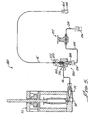
Fig. 5 is a schematic view of anelectrophoretic system 180 which operates in a similar manner assystems Figs. 1-4 . As in the case ofsystem 10 ofFig. 1 , insystem 180, gel is delivered by means of agel pump 30 where the pressure of the gel delivered is sensed bypressure sensor 34 and aback regulator 32 isolates pump 30 fromline 36 when the portion of thesystem 180 downstream fromline 36 is vented to the atmosphere.Line 36 is connected tomanifold 200 by means of anut 216 having grooves complementary to those of a hole in the manifold so that the nut can be screwed in the hole.Line 36 is threaded through a hole innut 216 and is sealingly held therein by means of non-conductive high pressure compression fitting. In this manner, high pressure gel can be delivered bypump 30 throughline 36 to a chamber withinmanifold 200. - The outlet end(s) of one or more capillaries 16' are enclosed within the chamber in the manifold 200 so that the gel delivered through
line 36 can be used to displace old gel in the capillary array 16' intoreservoir 104. As described in more detail below, electrode fitting 208 can be screwed into a threaded hole in the manifold 200, where the electrode fitting can be used as one terminal for applying electrical potential. Hence, if an electrical potential is applied betweenbuffer 104 and electrode fitting 208, the electric field present in the capillary array 16' may be used for electrophoretic separation. - Thus, as before, one or more samples may be introduced into the capillaries in array 16' through their ends 16'a. The separated components may be detected with the aid of
reflector 222 and a detector (not shown) indetection window 223. Some of the separated components may migrate into the chamber withinmanifold 200. To prevent the components from previous runs in such chamber from contaminating the gel to be delivered to the array 16', it will be desirable to purge the chamber withinmanifold 200 of the old gel prior to another electrophoretic run. Electrode fitting 208 has a hole therein through which the old gel in the chamber inmanifold 200 may be purged. For this purpose, anothergel line 214 for disposal of waste gel is connected to such hole in the electrode fitting by means of anothernut 216 which is screwed into a complementary hole withinelectrode fitting 208.Line 214 passes through a hole innut 216 and is sealingly attached thereto by non-conductive high pressure compression fitting. A waste valve 212 controlsline 214. Therefore, when the old gel within the chamber inmanifold 200 is to be purged, waste valve 212 is opened and pump 30 delivers new gel to the chamber in order to purge it of the old gel, which exits throughline 214 to wastereservoir 106. After the purging process, valve 212 is closed so that array 16' may then be purged by means of new gel frompump 30 as in systems described above and the system is then ready for another electrophoretic run. -
Fig. 6 is a perspective view of aportion 200 of theelectrophoretic system 180 ofFig. 5 including the manifold 202 with portions cut away to illustrate the preferred embodiment of the invention. In reference toFigs. 4 snd 6,system portion 200 may also be used to replaceportion 170' inFig. 4 . To simplify the drawing, thelenses 110b and photomultiplier tube 110c ofFig. 4 are not shown inFig. 6 , which shows only the parabolic mirror 110a. The connection between gel inlet line (similar toline 142 ofFig. 4 ) and theportion 200 also is not shown inFig. 6 ; such connection is illustrated inFigs. 7 and 8 .System portion 200 includes a manifold 202, a portion of which has been cut away to reveal the plurality of capillaries 16', parabolic mirror 110a,array holder 204,chamber 206, andelectrode fitting 208. The array of capillaries 16' pass through and are held in position by anarray holder 204 so that the ends 16a' remain inchamber 206.Array holder 204 has acylindrical portion 204a which fits snugly intochamber 206 and O-ring 210 provides a sealing connection between the array holder and the chamber wall ofchamber 206. Such sealing connection can withstand the required pressure of over 400 psi for the gel replacement process described above. Parabolic mirror 110a is mounted onto anannular member 222 which may slide alongguide 224. To assemble the manifold/reflector assembly portion 200 shown inFig. 6 ,cylindrical portion 204a ofholder 204 is sealingly connected to the chamber wall ofchamber 206 as described above, where theholder 204 holds the array of capillaries 16' with ends 16a' inside the chamber. To lock in the sealing connection,annular member 222 is slid alongguide 224 indirection 230 to engage the top surface ofarray holder 204, thereby locking the array holder in place. The top plate portion 204b has a wedge-shaped portion 204b' facingmember 222 to facilitate the sliding engagement withmember 222. Since theannular member 222 can only move alongdirection 230 or in the opposite direction to 230,array holder 204 will be locked in place untilannular member 222 is slid in a direction opposite to 230. - Electrical circuit for electrophoresis is completed through the gel medium in the capillaries 16', the gel medium in
chamber 206, the gel medium in electrode fitting 208 made of an electrically conductive material such as metal, as well as the fitting acting as an electrode. In this manner, no outlet buffer reservoir is required and the ground connection can be made directly to the electrode fitting. The other ends of capillaries 16' are connected to an inlet buffer reservoir (not shown), similar toreservoir 104 shown inFig. 4 . When the gel in capillaries 16' is to be replaced, fresh gel is injected intochamber 206 through an inlet (not shown) inFig. 6 but shown inFigs. 5 ,7 and 8 described below. As described above, in order to purgechamber 206 of old gel and any trapped gas and air bubbles, the waste valve 212 is opened, so that the old gel may be purged through fitting 208,line 214, valve 212 andreservoir 106. As shown inFig. 6 , fitting 208 defines two cylindrical holes 208a, 208b connected by a small hole 208c. As shown inFig. 5 , hole 208a is connected to line 214 through which the old gel fromchamber 206 may be purged to awaste container 106 inFig. 5 . -
Fig. 7 is a perspective view of thesystem portion 200 ofFig. 6 but from a different angle from the back.Fig. 8 is a cross-sectional view ofassembly portion 200 along the line 8-8 inFig. 7 . As shown inFigs. 7 and 8 , fresh gel may be injected by a syringe or pump (not shown) through a valve and line (not shown) togel inlet 232 for supplying fresh gel tochamber 206. -
Fig. 9A is a perspective view ofelectrode fitting 208. As shown inFigs. 8 and 9A ,portion 208' and 208" fit snugly (by means of complimentary threads) onto corresponding surfaces of a hole inmanifold 202 to withstand the over 400 psi pressure. As more clearly shown inFigs. 5 and8 , asmall hole 237 in the manifold 202 connects hole 208a (andline 214 ofFig. 5 ) through hole 208c tochamber 206.Fig. 9B is a top view of fitting 208 andFig. 9C is a cross-sectional view of the fitting. -
Manifold 202 may be made of a plastic material. In one embodiment, electrode fitting 208 has rounded surfaces to keep current density low. Theelectrode fitting 208 may be made of low resistance, electrically conductive material. - While the invention has been described above by reference to various embodiments, it will be understood that various changes and modifications may be made without departing from the scope of the invention which is to be defined only by the appended claims.
Claims (11)
- Electrophoretic separation apparatus comprising at least one separation capillary (16, 16', 18) capable of receiving a sample to be tested, said capillary (16, 16', 18) having a sample inlet and an outlet end,
said apparatus further comprising delivery means (30, 102) operable to deliver separation medium to said capillary (16, 16', 18) via a sample outlet end thereof and to a connector (T1, T2, U1), wherein the capillary (16, 16', 18) is in sealable communication at a sample outlet end thereof with the connector (T1, T2, U1); and a valving system operable between a first state in which separation medium is directed via the connector (T1,T2, U1) to said capillary (16, 16', 18) to provide separation medium replacement therein; a second state in which separation medium is directed to the connector (T1) such that same is purged of old separation medium,
the apparatus further comprises means for applying an electrical current between said input and output ends of the capillary (16, 16', 18), and wherein the valving system is operable to provide a third state in which the system is capable of electrophoresis whereby the sample is electrophoretically separated in said capillary (16, 16', 18) by application of the electrical current. - Electrophoretic separation apparatus according to claim 1 wherein the delivery means is a syringe (120).
- Electrophoretic separation apparatus according to claim 1 wherein the delivery means is a pump (30).
- Electrophoretic separation apparatus according to claim 3 wherein the apparatus further comprises a back pressure regulator (32) which disconnects the pump (30) from the valving system when pressure in the valving system is vented.
- Electrophoretic separation apparatus according to claim 3 wherein the apparatus further comprises a stepper motor (38) for controlling and monitoring the amount of separation medium delivered by the pump (30) to the said at least one capillary (16, 16', 18).
- Electrophoretic separation apparatus according to claim 5 wherein the apparatus further comprises a pressure sensor (34) for sensing pressure in the valving system when a predetermined amount of separation medium is delivered to said at least one capillary (16, 16', 18).
- Electrophoretic separation apparatus according to any one of claims 1 to 6 wherein the means for applying an electrical current includes an electrically conductive fixture or electrode.
- Electrophoretic separation apparatus according to claims 1 to 6 wherein the means for applying an electrical current includes one or more buffer solutions (104, 106).
- Electrophoretic separation apparatus according to claims 1 to 8 wherein the sealable communication at the sample output end of the capillary (16, 18, 16') with the connector is a high pressure seal.
- Electrophoretic separation apparatus according to claim 9 wherein the high pressure seal is capable of withstanding pressure of 400psi and above.
- Electrophoretic separation apparatus according to claims 1 to 10 wherein the apparatus additionally comprises means for purging the valving system of any bubbles as well as any sample components from previous electrophoretic runs.
Applications Claiming Priority (3)
| Application Number | Priority Date | Filing Date | Title |
|---|---|---|---|
| US518285 | 1995-08-23 | ||
| US08/518,285 US5635050A (en) | 1995-08-23 | 1995-08-23 | Electrophoretic system including means for replacing separation medium |
| PCT/US1996/013165 WO1997008545A1 (en) | 1995-08-23 | 1996-08-12 | Electrophoretic system including means for replacing separation medium |
Publications (2)
| Publication Number | Publication Date |
|---|---|
| EP0850412A1 EP0850412A1 (en) | 1998-07-01 |
| EP0850412B1 true EP0850412B1 (en) | 2013-01-02 |
Family
ID=24063314
Family Applications (1)
| Application Number | Title | Priority Date | Filing Date |
|---|---|---|---|
| EP96928167A Expired - Lifetime EP0850412B1 (en) | 1995-08-23 | 1996-08-12 | Electrophoretic system including means for replacing separation medium |
Country Status (4)
| Country | Link |
|---|---|
| US (1) | US5635050A (en) |
| EP (1) | EP0850412B1 (en) |
| JP (1) | JP3177896B2 (en) |
| WO (1) | WO1997008545A1 (en) |
Families Citing this family (31)
| Publication number | Priority date | Publication date | Assignee | Title |
|---|---|---|---|---|
| US6063251A (en) * | 1997-05-30 | 2000-05-16 | Spectrumedix Corporation | Electrically insulated capillary arrays for electrophoretic applications |
| US6027627A (en) * | 1997-06-30 | 2000-02-22 | Spectrumedix Corporation | Automated parallel capillary electrophoretic system |
| JP4121698B2 (en) * | 1997-06-30 | 2008-07-23 | アプレラ コーポレーション | Automated parallel capillary electrophoresis system |
| US6365024B1 (en) | 1997-06-30 | 2002-04-02 | Spectrumedix Corporation | Motorized positioning apparatus having coaxial carrousels |
| EP0905511A1 (en) * | 1997-09-25 | 1999-03-31 | Beckman Coulter, Inc. | Capillary holder |
| US6560859B1 (en) * | 1998-02-16 | 2003-05-13 | The Institute Of Physical And Chemical Research Shimadzu Corporation | Capillary cassette and method of producing the same |
| US6475361B1 (en) * | 1998-02-20 | 2002-11-05 | Tetragen Sa | Capillary electrophoresis apparatus having filling/refilling system and methods for use thereof |
| US6787111B2 (en) | 1998-07-02 | 2004-09-07 | Amersham Biosciences (Sv) Corp. | Apparatus and method for filling and cleaning channels and inlet ports in microchips used for biological analysis |
| JP2000162183A (en) * | 1998-11-30 | 2000-06-16 | Inst Of Physical & Chemical Res | Capillary electrophoresis device |
| US6352633B1 (en) * | 1999-08-31 | 2002-03-05 | Spectrumedix Corporation | Automated parallel capillary electrophoresis system with hydrodynamic sample injection |
| US7986729B2 (en) | 1999-10-28 | 2011-07-26 | Lightwaves Systems, Inc. | High bandwidth data transport system |
| JP3389547B2 (en) * | 2000-02-28 | 2003-03-24 | 株式会社日立製作所 | Electrophoresis device |
| JP3882484B2 (en) * | 2000-08-25 | 2007-02-14 | 株式会社日立製作所 | Electrophoresis method, electrophoresis apparatus and capillary array |
| US7309409B2 (en) * | 2001-01-26 | 2007-12-18 | Biocal Technology, Inc. | Multi-channel bio-separation cartridge |
| US8766773B2 (en) | 2001-03-20 | 2014-07-01 | Lightwaves Systems, Inc. | Ultra wideband radio frequency identification system, method, and apparatus |
| US7545868B2 (en) | 2001-03-20 | 2009-06-09 | Lightwaves Systems, Inc. | High bandwidth data transport system |
| US7983349B2 (en) | 2001-03-20 | 2011-07-19 | Lightwaves Systems, Inc. | High bandwidth data transport system |
| US7081191B2 (en) * | 2002-01-18 | 2006-07-25 | Hitachi High-Technologies Corporation | Capillary electrophoresis device |
| US7208072B2 (en) * | 2002-01-18 | 2007-04-24 | Biocal Technology, Inc. | Multi-segment cartridge for bio-separation with multiplexed fluorescence detection |
| WO2004003505A2 (en) * | 2002-06-27 | 2004-01-08 | University Of Marlyland, Baltimore | Methods for detecting and inactivating a prion |
| US7534335B2 (en) * | 2003-02-28 | 2009-05-19 | Combisep, Inc. | Multiplexed, absorbance-based capillary electrophoresis system and method |
| US20090068640A1 (en) * | 2003-06-27 | 2009-03-12 | Robert Rohwer | Methods for detecting and inactivating a prion |
| JP4857088B2 (en) * | 2006-11-22 | 2012-01-18 | 株式会社日立ハイテクノロジーズ | Electrophoresis device |
| JP2007171216A (en) * | 2007-03-26 | 2007-07-05 | Hitachi Ltd | Capillary array electrophoresis apparatus and sample separation / analysis method |
| WO2008136057A1 (en) * | 2007-04-25 | 2008-11-13 | Shimadzu Corporation | Electrophoretic chip and method of electrophoresis |
| US20110301539A1 (en) * | 2010-06-08 | 2011-12-08 | Rickard Matthew J A | Fill and purge system for a drug reservoir |
| DE112015006171B4 (en) | 2015-03-27 | 2024-03-28 | Hitachi High-Tech Corporation | Electrophoresis device and electrophoresis method |
| WO2018217816A1 (en) | 2017-05-22 | 2018-11-29 | Integenx Inc. | Compositions, methods, kits and devices for molecular analysis |
| CN111344562B (en) | 2017-05-22 | 2023-09-12 | 因特根克斯股份有限公司 | Compositions, methods, kits and devices for molecular analysis |
| CN111133307B (en) * | 2017-09-26 | 2023-02-21 | 株式会社日立高新技术 | Capillary electrophoresis device |
| JP6851953B2 (en) * | 2017-10-30 | 2021-03-31 | アークレイ株式会社 | Pump drive method |
Family Cites Families (4)
| Publication number | Priority date | Publication date | Assignee | Title |
|---|---|---|---|---|
| US5427729A (en) * | 1989-10-03 | 1995-06-27 | The Perkin-Elmer Corporation | Method of making gel packed columns suitable for use in chromatography |
| US5037523A (en) * | 1990-01-25 | 1991-08-06 | Spectra-Physics, Inc. | Air cooled cartridge for capillary electrophoresis |
| US5332481A (en) * | 1991-01-29 | 1994-07-26 | Beckman Instruments, Inc. | Capillary electrophoresis using replaceable gels |
| EP0607495B1 (en) * | 1992-08-26 | 1998-01-14 | Hitachi, Ltd. | Capillary electrophoresis |
-
1995
- 1995-08-23 US US08/518,285 patent/US5635050A/en not_active Expired - Lifetime
-
1996
- 1996-08-12 JP JP51032697A patent/JP3177896B2/en not_active Expired - Lifetime
- 1996-08-12 WO PCT/US1996/013165 patent/WO1997008545A1/en not_active Ceased
- 1996-08-12 EP EP96928167A patent/EP0850412B1/en not_active Expired - Lifetime
Also Published As
| Publication number | Publication date |
|---|---|
| JPH11511555A (en) | 1999-10-05 |
| EP0850412A1 (en) | 1998-07-01 |
| JP3177896B2 (en) | 2001-06-18 |
| US5635050A (en) | 1997-06-03 |
| WO1997008545A1 (en) | 1997-03-06 |
Similar Documents
| Publication | Publication Date | Title |
|---|---|---|
| US5635050A (en) | Electrophoretic system including means for replacing separation medium | |
| US5573651A (en) | Apparatus and method for flow injection analysis | |
| US6375819B1 (en) | Fluid delivery system for capillary electrophoretic applications | |
| EP0475533B1 (en) | Method and apparatus for the introduction of a volume of at least one fluid in a tube, in particular suitable for capillary electrophoresis systems and method and apparatus for separating and/or analyzing a fluid material | |
| US6027627A (en) | Automated parallel capillary electrophoretic system | |
| JP3690985B2 (en) | Multi-channel capillary electrophoresis apparatus including a sheath flow cuvette and a replaceable capillary array | |
| US6953521B2 (en) | Automated parallel capillary electrophoresis system with hydrodynamic sample injection | |
| AU708739B2 (en) | Method and apparatus for reducing the distortion of a sample zone eluting from a capillary electrophoresis capillary | |
| US5985121A (en) | Fast sampling device and sampling method for capillary electrophoresis | |
| EP0617278A1 (en) | Connectorized capillaries for use with separation instrumentation components | |
| US20040124085A1 (en) | Microfluidic devices and methods with electrochemically actuated sample processing | |
| US20110031268A1 (en) | Electrokinetic pump designs and drug delivery systems | |
| US5141621A (en) | Capillary electrophoresis injection device and method | |
| CA2436136A1 (en) | Multi-channel bio-separation cartridge | |
| de Jesus et al. | Microchip free‐flow electrophoresis on glass substrate using laser‐printing toner as structural material | |
| EP0441463B1 (en) | Capillary electrophoresis technique | |
| US8834697B2 (en) | Electrophoresis apparatus and a method for electrophoresis | |
| US6383356B1 (en) | Capillary electrophoretic apparatus | |
| US3826730A (en) | Disposable electrochemical electrode | |
| CA1322221C (en) | Automated capillary electrophoresis apparatus | |
| CA2295227C (en) | Automated parallel capillary electrophoretic system | |
| US3346486A (en) | Apparatus and method for introduction of amino acid samples into a chromatography column | |
| US20080116073A1 (en) | Electrophoretic apparatus | |
| EP0448313A2 (en) | Retractable member for fluid, optical and electrical communication in capillary zone electrophoresis | |
| US5900132A (en) | Capillary holder |
Legal Events
| Date | Code | Title | Description |
|---|---|---|---|
| PUAI | Public reference made under article 153(3) epc to a published international application that has entered the european phase |
Free format text: ORIGINAL CODE: 0009012 |
|
| 17P | Request for examination filed |
Effective date: 19980225 |
|
| AK | Designated contracting states |
Kind code of ref document: A1 Designated state(s): DE FR GB IT |
|
| RAP1 | Party data changed (applicant data changed or rights of an application transferred) |
Owner name: BECKMAN COULTER, INC. |
|
| 17Q | First examination report despatched |
Effective date: 20010216 |
|
| APBN | Date of receipt of notice of appeal recorded |
Free format text: ORIGINAL CODE: EPIDOSNNOA2E |
|
| APBR | Date of receipt of statement of grounds of appeal recorded |
Free format text: ORIGINAL CODE: EPIDOSNNOA3E |
|
| APBV | Interlocutory revision of appeal recorded |
Free format text: ORIGINAL CODE: EPIDOSNIRAPE |
|
| APAF | Appeal reference modified |
Free format text: ORIGINAL CODE: EPIDOSCREFNE |
|
| RAP1 | Party data changed (applicant data changed or rights of an application transferred) |
Owner name: BECKMAN COULTER, INC. |
|
| APBT | Appeal procedure closed |
Free format text: ORIGINAL CODE: EPIDOSNNOA9E |
|
| GRAP | Despatch of communication of intention to grant a patent |
Free format text: ORIGINAL CODE: EPIDOSNIGR1 |
|
| GRAS | Grant fee paid |
Free format text: ORIGINAL CODE: EPIDOSNIGR3 |
|
| GRAA | (expected) grant |
Free format text: ORIGINAL CODE: 0009210 |
|
| AK | Designated contracting states |
Kind code of ref document: B1 Designated state(s): DE FR GB IT |
|
| REG | Reference to a national code |
Ref country code: GB Ref legal event code: FG4D |
|
| REG | Reference to a national code |
Ref country code: DE Ref legal event code: R096 Ref document number: 69638546 Country of ref document: DE Effective date: 20130228 |
|
| PLBE | No opposition filed within time limit |
Free format text: ORIGINAL CODE: 0009261 |
|
| STAA | Information on the status of an ep patent application or granted ep patent |
Free format text: STATUS: NO OPPOSITION FILED WITHIN TIME LIMIT |
|
| 26N | No opposition filed |
Effective date: 20131003 |
|
| PG25 | Lapsed in a contracting state [announced via postgrant information from national office to epo] |
Ref country code: IT Free format text: LAPSE BECAUSE OF FAILURE TO SUBMIT A TRANSLATION OF THE DESCRIPTION OR TO PAY THE FEE WITHIN THE PRESCRIBED TIME-LIMIT Effective date: 20130102 |
|
| REG | Reference to a national code |
Ref country code: DE Ref legal event code: R097 Ref document number: 69638546 Country of ref document: DE Effective date: 20131003 |
|
| REG | Reference to a national code |
Ref country code: FR Ref legal event code: PLFP Year of fee payment: 20 |
|
| PGFP | Annual fee paid to national office [announced via postgrant information from national office to epo] |
Ref country code: GB Payment date: 20150827 Year of fee payment: 20 Ref country code: DE Payment date: 20150827 Year of fee payment: 20 |
|
| PGFP | Annual fee paid to national office [announced via postgrant information from national office to epo] |
Ref country code: FR Payment date: 20150817 Year of fee payment: 20 |
|
| REG | Reference to a national code |
Ref country code: DE Ref legal event code: R071 Ref document number: 69638546 Country of ref document: DE |
|
| REG | Reference to a national code |
Ref country code: GB Ref legal event code: PE20 Expiry date: 20160811 |
|
| PG25 | Lapsed in a contracting state [announced via postgrant information from national office to epo] |
Ref country code: GB Free format text: LAPSE BECAUSE OF EXPIRATION OF PROTECTION Effective date: 20160811 |