EP0848802B1 - Polymer film heat exchanger - Google Patents
Polymer film heat exchanger Download PDFInfo
- Publication number
- EP0848802B1 EP0848802B1 EP96929427A EP96929427A EP0848802B1 EP 0848802 B1 EP0848802 B1 EP 0848802B1 EP 96929427 A EP96929427 A EP 96929427A EP 96929427 A EP96929427 A EP 96929427A EP 0848802 B1 EP0848802 B1 EP 0848802B1
- Authority
- EP
- European Patent Office
- Prior art keywords
- fluid
- bilayer
- heat exchanger
- bilayer according
- fluids
- Prior art date
- Legal status (The legal status is an assumption and is not a legal conclusion. Google has not performed a legal analysis and makes no representation as to the accuracy of the status listed.)
- Expired - Lifetime
Links
- 229920006254 polymer film Polymers 0.000 title claims description 22
- 239000012530 fluid Substances 0.000 claims description 72
- 239000007789 gas Substances 0.000 claims description 17
- 239000007788 liquid Substances 0.000 claims description 17
- 239000011159 matrix material Substances 0.000 claims description 11
- 238000000034 method Methods 0.000 claims description 8
- 238000001816 cooling Methods 0.000 claims description 6
- 239000003546 flue gas Substances 0.000 claims description 6
- 238000002360 preparation method Methods 0.000 claims description 6
- UGFAIRIUMAVXCW-UHFFFAOYSA-N Carbon monoxide Chemical compound [O+]#[C-] UGFAIRIUMAVXCW-UHFFFAOYSA-N 0.000 claims description 5
- 239000002826 coolant Substances 0.000 claims description 4
- 238000011084 recovery Methods 0.000 claims description 4
- 239000002699 waste material Substances 0.000 claims description 4
- 238000007789 sealing Methods 0.000 claims description 2
- 229920000642 polymer Polymers 0.000 description 9
- 238000012546 transfer Methods 0.000 description 8
- XLYOFNOQVPJJNP-UHFFFAOYSA-N water Substances O XLYOFNOQVPJJNP-UHFFFAOYSA-N 0.000 description 6
- 239000004696 Poly ether ether ketone Substances 0.000 description 5
- 229920002530 polyetherether ketone Polymers 0.000 description 5
- 238000002156 mixing Methods 0.000 description 4
- 238000013461 design Methods 0.000 description 3
- 239000000463 material Substances 0.000 description 3
- 239000002184 metal Substances 0.000 description 3
- 229910052751 metal Inorganic materials 0.000 description 3
- 229920001646 UPILEX Polymers 0.000 description 2
- 238000010276 construction Methods 0.000 description 2
- 238000009826 distribution Methods 0.000 description 2
- 238000004519 manufacturing process Methods 0.000 description 2
- 150000002739 metals Chemical class 0.000 description 2
- -1 polyethylene Polymers 0.000 description 2
- 238000012545 processing Methods 0.000 description 2
- 230000002787 reinforcement Effects 0.000 description 2
- 229920001169 thermoplastic Polymers 0.000 description 2
- 238000004804 winding Methods 0.000 description 2
- OKTJSMMVPCPJKN-UHFFFAOYSA-N Carbon Chemical compound [C] OKTJSMMVPCPJKN-UHFFFAOYSA-N 0.000 description 1
- 229910001018 Cast iron Inorganic materials 0.000 description 1
- XEEYBQQBJWHFJM-UHFFFAOYSA-N Iron Chemical group [Fe] XEEYBQQBJWHFJM-UHFFFAOYSA-N 0.000 description 1
- 239000004698 Polyethylene Substances 0.000 description 1
- 239000004642 Polyimide Substances 0.000 description 1
- 239000004743 Polypropylene Substances 0.000 description 1
- 230000002378 acidificating effect Effects 0.000 description 1
- 230000015572 biosynthetic process Effects 0.000 description 1
- 230000000903 blocking effect Effects 0.000 description 1
- 229910052799 carbon Inorganic materials 0.000 description 1
- 238000002485 combustion reaction Methods 0.000 description 1
- 239000000356 contaminant Substances 0.000 description 1
- 239000000498 cooling water Substances 0.000 description 1
- 230000003247 decreasing effect Effects 0.000 description 1
- 238000001704 evaporation Methods 0.000 description 1
- 230000008020 evaporation Effects 0.000 description 1
- 230000001747 exhibiting effect Effects 0.000 description 1
- 230000002349 favourable effect Effects 0.000 description 1
- 239000000835 fiber Substances 0.000 description 1
- 238000001914 filtration Methods 0.000 description 1
- 239000003365 glass fiber Substances 0.000 description 1
- 238000011835 investigation Methods 0.000 description 1
- 229920000573 polyethylene Polymers 0.000 description 1
- 239000011112 polyethylene naphthalate Substances 0.000 description 1
- 229920001721 polyimide Polymers 0.000 description 1
- 229920001155 polypropylene Polymers 0.000 description 1
- 239000004800 polyvinyl chloride Substances 0.000 description 1
- 238000010248 power generation Methods 0.000 description 1
- 230000000452 restraining effect Effects 0.000 description 1
- 238000000926 separation method Methods 0.000 description 1
- 239000007787 solid Substances 0.000 description 1
- 229910001220 stainless steel Inorganic materials 0.000 description 1
- 239000010935 stainless steel Substances 0.000 description 1
- 239000000126 substance Substances 0.000 description 1
- 238000012360 testing method Methods 0.000 description 1
- 239000004416 thermosoftening plastic Substances 0.000 description 1
- 230000007704 transition Effects 0.000 description 1
- 238000005406 washing Methods 0.000 description 1
Images


Classifications
-
- F—MECHANICAL ENGINEERING; LIGHTING; HEATING; WEAPONS; BLASTING
- F28—HEAT EXCHANGE IN GENERAL
- F28D—HEAT-EXCHANGE APPARATUS, NOT PROVIDED FOR IN ANOTHER SUBCLASS, IN WHICH THE HEAT-EXCHANGE MEDIA DO NOT COME INTO DIRECT CONTACT
- F28D9/00—Heat-exchange apparatus having stationary plate-like or laminated conduit assemblies for both heat-exchange media, the media being in contact with different sides of a conduit wall
- F28D9/04—Heat-exchange apparatus having stationary plate-like or laminated conduit assemblies for both heat-exchange media, the media being in contact with different sides of a conduit wall the conduits being formed by spirally-wound plates or laminae
-
- F—MECHANICAL ENGINEERING; LIGHTING; HEATING; WEAPONS; BLASTING
- F28—HEAT EXCHANGE IN GENERAL
- F28F—DETAILS OF HEAT-EXCHANGE AND HEAT-TRANSFER APPARATUS, OF GENERAL APPLICATION
- F28F21/00—Constructions of heat-exchange apparatus characterised by the selection of particular materials
- F28F21/06—Constructions of heat-exchange apparatus characterised by the selection of particular materials of plastics material
- F28F21/065—Constructions of heat-exchange apparatus characterised by the selection of particular materials of plastics material the heat-exchange apparatus employing plate-like or laminated conduits
-
- Y—GENERAL TAGGING OF NEW TECHNOLOGICAL DEVELOPMENTS; GENERAL TAGGING OF CROSS-SECTIONAL TECHNOLOGIES SPANNING OVER SEVERAL SECTIONS OF THE IPC; TECHNICAL SUBJECTS COVERED BY FORMER USPC CROSS-REFERENCE ART COLLECTIONS [XRACs] AND DIGESTS
- Y10—TECHNICAL SUBJECTS COVERED BY FORMER USPC
- Y10S—TECHNICAL SUBJECTS COVERED BY FORMER USPC CROSS-REFERENCE ART COLLECTIONS [XRACs] AND DIGESTS
- Y10S165/00—Heat exchange
- Y10S165/905—Materials of manufacture
Definitions
- the present invention relates to novel polymer film bilayers for non mixing contact of fluids, heat exchangers comprising such bilayers, the preparation and uses thereof, in particular to polymer film heat exchangers having a favourable ratio of heat exchanging surface area to path length of gas and/or liquids, processes for the preparation thereof and applications thereof.
- EP-A-0 397 487 discloses two polymer films sealed together to form a bilayer used as a heat exchanger.
- the thermal conductivity of polymers is poor compared with that of metals so it is important that the thickness of polymer used does not impose a significant extra thermal resistance upon the heat transfer process.
- the film is corrugated so that adjacent film layers may be held apart by the corrugations which may cross at approximately 90°. Where heat is being transferred from fluid A to fluid B, these fluids flow alternately through layers of corrugated film.
- the present invention relates to a bilayer of corrugated polymer film arranged so that the corrugations cross at an angle to create respective flow paths for a first and second gaseous or liquid fluid, wherein the ratio of the surface area of polymer film, defined as the total surface including that of the flow paths of the fluids, adapted to contact both fluids, to the total matrix volume, defined as the total volume of the bilayer, including that at the external surface thereof, but excluding supply and effluent manifolds volume and deadspace which is adapted to be contacted by first or second fluid, is in excess of 700m 2 /m 3 , characterised in that adjacent polymer film layers are held apart by the corrugations.
- the ratio is in excess of 1000 m 2 /m 3 , for example is of the order of 1500 m 2 /m 3 . It is a particular advantage that these ratios may be obtained with use of a polymer, with associated manufacturing efficiency, and with acceptable pressure drop.
- the bilayer of the present invention it is possible to provide a total surface area to path length of heat exchanging gas and liquid which is economically attractive and yet wherein the bilayer is such as to ensure acceptable pressure drop, thereby avoiding leakage and failure thereof.
- the bilayer is ideally suited for use in heat exchanging application.
- Reference herein to matrix volume is to the total volume defined by the bilayer, including the volume defined by the external surface thereof, which is adapted to be contacted by first or second fluid, but excluding supply and effluent manifolds volume and deadspace, for example such as provided by a mandrel as hereinbelow described.
- Gaseous and liquid fluids for heat exchanging purposes may be selected from any fluids conventionally employed for such purpose, in particular fluids to be cooled such as flue gases, engine, machinery, processing and furnace or motor coolants or the like, in particular for the recovery of heat energy, or for heat energy recovery purposes from hot waste fluids, such as washing machine or like domestic or industrial appliance effluent.
- fluids to be cooled such as flue gases, engine, machinery, processing and furnace or motor coolants or the like, in particular for the recovery of heat energy, or for heat energy recovery purposes from hot waste fluids, such as washing machine or like domestic or industrial appliance effluent.
- the path length of first fluid is less than the path length of second fluid.
- a bilayer as hereinbefore defined comprises two corrugated polymer films arranged at an angle of cross corrugation of 25° to 90°, more preferably arranged at an angle of 60° to 90° in the event the fluid flow paths are comprised substantially in a straight plane, or of 25° to 60° in the event that flow paths are comprised in a substantially curved or angled plane.
- Corrugated polymer films may be comprised of any suitable polymer exhibiting thermoplastic properties, for example polyethylene such as polyethylene naphthalate (PEN), polypropylene, polyvinylchloride (PVC) and as hereinbefore defined (PEEK and UPILEX) having suitable working temperatures and flexibility and resilience.
- the films may comprise suitable fibre reinforcement and the like as is known in the art, preferably comprise carbon or glass fibre reinforcement.
- the films may be obtained pre-corrugated or may be corrugated in the process for the preparation of the bilayer using known techniques.
- Corrugated polymer films may have any desired profile adapted to create and regulate a desired flow path therebetween, preferably may comprise a sinusoidal, saw tooth, square-sinusoidal profile or the like.
- Corrugation wavelength is conveniently measured in terms of peak to peak separation, and may be of any suitable value adapted for the desired heat exchanging duty and acceptable pressure drop, also adapted to allow for passage of any solid contaminants without blocking in the event that filtration is ineffective or undesirable.
- Preferably wavelength is of the order of up to 1cm, more preferably in the range 1 to 6 mm, such as for example 2 to 4 mm.
- Choice of corrugation profile may conveniently be made with reference to the mixing and distribution characteristics required for a given application.
- Angle of cross corrugation may suitably be selected according to mixing and distribution characteristics required for a given application, whereby a large cross-corrugation angle provides greater fluid flow path volume and hence less pressure drop, but less bilayer flexibility to desired deformation.
- a bilayer may be employed which occupies a small total matrix volume as hereinbefore defined, and yet which provides similar or superior fluid contacting with respect to conventional heat exchange elements.
- a bilayer as hereinbefore defined may be elongate and formed into a geometric form whereof the longest dimension is less than the path length of second fluid, and whereby the number of discrete first fluid paths is greater than that which would be provided by a straight planar bilayer having the same longest dimension.
- the geometric form of a bilayer may be selected according to the desired application, in particular with reference to the physical and mechanical constraints and volume to be accommodated.
- a single bilayer is adapted for the passage of a first fluid and second fluid in cross directions, one of which is contained within the bilayer and thereby isolated from the other which contacts the outer surface of the bilayer, along the external corrugations thereof.
- a bilayer is sealed in known manner at its periphery to contain the second fluid in suitable manner.
- a bilayer is formed into an open, closed or concentric spiral plane which is curved or angled, such as an elliptical, circular or polygonal plane or part or combination thereof. It will be appreciated that such bilayer may be one of a plurality of substantially coplanar bilayers arranged in coaxial, concentric or equivalent manner.
- Reference to a concentric spiral plane which is curved or angled is to a plane which is coiled or wound in on itself in manner such that it forms a geometric body of which a cross section comprises a two-dimensional curved or angled spiral.
- an angled plane comprises continuous angles at each transition between spirals and each geometric angle respectively, thereby minimising the pressure drop along the second fluid path length.
- the bilayers of the invention are thereby adapted for the selection of first fluid path length with reference to the number of coplanar bilayers or of concentric spirals thereof, ie comprising a substantially constant number of first fluid path lengths per bilayer or section, to obtain a desired cross sectional area of non-mixing contact of first and second fluid within a desired first fluid pressure drop constraint.
- a bilayer which is one of a plurality of corresponding bilayers or which comprises a concentric spiral is adapted to provide for passage of one of a first and second fluid enclosed within each separate bilayer or concentric portion thereof and isolated from the other of the first and second fluid which is adapted to pass between and contact the external surfaces of each of any two coplanar bilayers or concentric portions thereof, ie the plurality of corresponding bilayers or concentric portions thereof may be arranged in the first or second fluid flow path whereby the first or second fluid is able to pass therebetween, along the external corrugations thereof.
- the bilayers of the invention are essentially scale independent, having regard to the ability to select the first fluid (and second fluid) path lengths thereof.
- a bilayer may have a total first fluid path length of 1 cm to 5 metres or more and a total second fluid path length of 10 cm to 50 metres or more, corresponding to a greatest geometric form dimension of 1 cm to 10 metres or more.
- a bilayer as hereinbefore defined may be formed with respective ends of the first and/or second fluid path associated with first and/or second fluid supply and effluent manifolds.
- a bilayer which is one of a plurality of substantially coplanar bilayers is associated with each of a single supply and effluent manifold common to each of the coplanar bilayers.
- a bilayer which is formed into a part of a geometric form and is aligned end-to-end with one or more bilayers comprising the remaining parts of the geometric form may be associated with each of a single supply and effluent manifold in common with co-aligned bilayers. Arrangement of manifolds will however be determined with reference to ease of access and connection consideration and the like.
- a process for the preparation of a bilayer as hereinbefore defined comprising the assembly of two polymer films as hereinbefore defined, and the sealing thereof preferably two films are moulded to obtain the desired corrugation to obtain the desired configuration and simultaneously or otherwise are sealed and are formed to obtain the desired configuration as hereinbefore defined, preferably are simultaneously moulded to obtain the desired corrugation and geometric form.
- pre-corrugated film may be cut and formed as desired with minimal costs or that film may be corrugated and formed simultaneously with use of a dedicated template or die with associated higher product quality.
- a fluid heat exchanger comprising a bilayer as hereinbefore defined.
- a heat exchanger as hereinbefore defined comprises a mandrel of corresponding form and dimensions to the space enclosed by the heat exchanger, adapted to be located in a first fluid flow path having corresponding form and dimensions adapted to enclose the heat exchanger.
- an axial mandrel within a heat exchanger positioned within the first fluid flow path as hereinbefore defined, ensures that the first fluid contacts the external surface(s) of the bilayer(s), ensuring effective heat exchange.
- the mandrel may be constructed of any suitable material, but is preferably constructed of a material matching the physical constraints of the intended application.
- the mandrel is hollow thereby reducing the mass thereof, more preferably is constructed of a resilient polymer, for example a thermoplastic polymer as hereinbefore defined, and has wall thickness sufficient to provide the required length.
- a heat exchanger as hereinbefore defined comprising a bilayer as hereinbefore defined for heat exchange application wherein the first fluid is gas and the second fluid is liquid, selected from fluids commonly employed in cooling heat exchange applications, such as flue gas, engine, machinery, furnace or motor coolants, waste industrial and domestic appliance effluents, and fluids commonly employed for the recovery of heat energy therefrom.
- a corrugated polymer film heat exchanger matrix is provided, constructed for example as described below, having one or more of the following principle advantages:
- a secondary heat exchanger for a 15 kW condensing domestic water heater is typically designed to recover 3 kW by cooling the flue gas from 250° C to 50°C (approximately) with water entering at 50°C. This corresponds to a mean temperature difference of about 80°C.
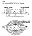
- the heat transfer area required for this duty is 0.2 m 2 . It is proposed to generate this area by bonding two corrugated strips 10 cm wide and 1m long at their periphery as shown in Figure 1. The corrugations are aligned at 45°C to the strip length but cross at 90° in order to hold the strips apart. Thus a flow channel is created for the water which passes between the inlet/outlet ports provided at each end.
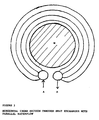
- the polymer strip is then wound on a cylindrical mandrel having a diameter large enough to avoid "kinking" of the channel as the spiral matrix is generated. With 100 ⁇ m thick corrugated PEEK film this diameter will typically be at least 7 cm.
- the heat exchanger spiral is secured by a restraining cylindrical band, thereby generating a heat exchanger cartridge which may conveniently be installed in a gas duct.
- a one metre strip corrugated as described above will wind into a spiral approximately 7 cm inner diameter and 9 cm outer diameter.
- the central mandrel is blocked in order that the gas is compelled to flow between the liquid-cooled spiral strips giving a flow path length of 10 cm.
- narrower strips may be wound to produce a cartridge of larger outside diameter.
- FIG. 3 shows the envisaged arrangement with four strips which have common water feed and return headers, A,B.
- the strips are wound around the mandrel M which is of such diameter as to prevent "kinking" of the strips.
- the length of each strip is cut so as to ensure that each is in snug contact with its neighbour along its entirety. The location and bonding of the ends of the strips into the headers is a straightforward matter to those skilled in the art of polymer fabrication.
- Figure 4 is shown a heat exchanger as described in respect of Figure 3, for use in cooling water effluent from power generation turbines, processing plants and the like. Traditional cooling towers are thereby dispensed with and dry cooling is employed, eliminating the present evaporation waste problems.
- the heat exchanger of Figure 4 may be 50 m diameter or more, whereby cross-corrugation angles of 90° are found to be satisfactory.
Landscapes
- Engineering & Computer Science (AREA)
- Physics & Mathematics (AREA)
- Thermal Sciences (AREA)
- Mechanical Engineering (AREA)
- General Engineering & Computer Science (AREA)
- Heat-Exchange Devices With Radiators And Conduit Assemblies (AREA)
Description
Claims (12)
- A bilayer of corrugated polymer film arranged so that the corrugations cross at an angle to create respective flow paths for a first and second gaseous or liquid fluid, wherein the ratio of the surface area of polymer film, defined as the total surface including that of the flow paths of the fluids, adapted to contact both fluids, to the total matrix volume, defined as the total volume of the bilayer, including that at the external surface thereof, but excluding supply and effluent manifolds volume and deadspace which is adapted to be contacted by first or second fluid, is in excess of 700m2/m3, characterised in that adjacent polymer film layers are held apart by the corrugations.
- A bilayer according to claim 1 wherein the path length of first fluid is less than the path length of second fluid.
- A bilayer according to claim 1 or 2 comprising two corrugated polymer films arranged at an angle of cross corrugation of 25° to 90°.
- A bilayer according to claims 1 to 3 which is elongate and is formed into a geometric form whereof the longest dimension is less than the path length of second fluid, and whereby the number of discrete first fluid paths is greater than that which would be provided by a straight planar bilayer having the same longest dimension.
- A bilayer according to any of claims 1 to 4 which is formed into an open, closed or concentric spiral plane which is curved or angled, such as an elliptical, circular or polygonal plane or part or combination thereof.
- A bilayer according to any of claims 1 to 5 which is one of a plurality of substantially coplanar bilayers arranged in coaxial, concentric or equivalent manner.
- A bilayer according to claims 1 to 6 which is formed with respective ends of the first and/or second fluid path associated with first and/or second fluid supply and effluent manifolds.
- A bilayer according to any of claims 1 to 7, which is a fluid heat exchanger.
- A bilayer according to claim 8 which comprises a mandrel of corresponding form and dimensions to the space enclosed by the heat exchanger, adapted to be located in a first fluid flow path having corresponding form and dimensions adapted to enclose the heat exchanger.
- A bilayer as hereinbefore defined with reference to claims 1 to 9 for use in heat exchange application wherein the first fluid is gas and the second fluid is liquid, selected from fluids commonly employed in cooling heat exchange applications, such as flue gas, engine, machinery, furnace or motor coolants, waste industrial and domestic appliance effluents, and fluids commonly employed for the recovery of heat energy therefrom.
- Process for the preparation of a bilayer according to any of claims 1 to 9 comprising the assembly of two polymer films as defined, in any of claims 1 to 9, and the sealing thereof.
- Process according to claim 11 for the preparation of a bilayer according to any of claims 3 to 9 wherein the two films are moulded to obtain the desired corrugation and simultaneously are sealed.
Applications Claiming Priority (3)
| Application Number | Priority Date | Filing Date | Title |
|---|---|---|---|
| GB9518260 | 1995-09-08 | ||
| GBGB9518260.6A GB9518260D0 (en) | 1995-09-08 | 1995-09-08 | Polymer film heat exchanger |
| PCT/GB1996/002189 WO1997009579A1 (en) | 1995-09-08 | 1996-09-04 | Polymer film heat exchanger |
Publications (2)
| Publication Number | Publication Date |
|---|---|
| EP0848802A1 EP0848802A1 (en) | 1998-06-24 |
| EP0848802B1 true EP0848802B1 (en) | 2003-04-16 |
Family
ID=10780336
Family Applications (1)
| Application Number | Title | Priority Date | Filing Date |
|---|---|---|---|
| EP96929427A Expired - Lifetime EP0848802B1 (en) | 1995-09-08 | 1996-09-04 | Polymer film heat exchanger |
Country Status (6)
| Country | Link |
|---|---|
| US (1) | US6059024A (en) |
| EP (1) | EP0848802B1 (en) |
| AU (1) | AU6883996A (en) |
| DE (1) | DE69627511T2 (en) |
| GB (1) | GB9518260D0 (en) |
| WO (1) | WO1997009579A1 (en) |
Families Citing this family (16)
| Publication number | Priority date | Publication date | Assignee | Title |
|---|---|---|---|---|
| US6497841B1 (en) | 1997-07-22 | 2002-12-24 | Medtronic, Inc. | Prevention of electrical discharges in polymeric heat exchangers |
| GB9923626D0 (en) * | 1999-10-07 | 1999-12-08 | Univ Newcastle | Novel porous element and use thereof |
| US7077643B2 (en) * | 2001-11-07 | 2006-07-18 | Battelle Memorial Institute | Microcombustors, microreformers, and methods for combusting and for reforming fluids |
| US20050139344A1 (en) * | 2002-02-27 | 2005-06-30 | Butler Barry L. | Internal water tank solar heat exchanger |
| US6827128B2 (en) * | 2002-05-20 | 2004-12-07 | The Board Of Trustees Of The University Of Illinois | Flexible microchannel heat exchanger |
| JP2004060986A (en) * | 2002-07-29 | 2004-02-26 | Ube Ind Ltd | Flexible heat exchanger and method of manufacturing the same |
| KR101230694B1 (en) * | 2003-12-22 | 2013-02-07 | 엔테그리스, 아이엔씨. | Exchange devices with potted hollow conduits |
| US20060000590A1 (en) * | 2004-06-09 | 2006-01-05 | Integral Technologies, Inc. | Low cost vehicle heat exchange devices manufactured from conductive loaded resin-based materials |
| JP4305406B2 (en) * | 2005-03-18 | 2009-07-29 | 三菱電機株式会社 | Cooling structure |
| US7534349B2 (en) * | 2005-09-02 | 2009-05-19 | Nephros, Inc. | Dual stage ultrafilter devices in the form of portable filter devices, shower devices, and hydration packs |
| US7775375B2 (en) * | 2005-11-03 | 2010-08-17 | Medica S.R.L. | Redundant ultrafiltration device |
| DE102006036965A1 (en) * | 2006-08-01 | 2008-02-07 | Makatec Gmbh | Heat exchanger e.g. foil heat exchanger, for transferring heat between fluids, has thin, flexible plastic containing foils utilized as heat transferring surfaces between flow channels of fluids, where surfaces are designed from foils layers |
| US20100132930A1 (en) * | 2007-05-02 | 2010-06-03 | Creare, Inc. | Flexible Heat/Mass Exchanger |
| DE202009003521U1 (en) * | 2009-03-04 | 2009-06-04 | Makatec Gmbh | Heat exchanger for oil cooling |
| WO2014036476A2 (en) * | 2012-08-31 | 2014-03-06 | State Of Oregon Acting By And Through The State Board Of Higher Education On Behalf Of Oregon State University | System and method for storing energy and purifying fluid |
| US10233839B2 (en) | 2013-08-16 | 2019-03-19 | General Electric Company | Composite heat exchanger |
Family Cites Families (19)
| Publication number | Priority date | Publication date | Assignee | Title |
|---|---|---|---|---|
| DE835008C (en) * | 1943-12-14 | 1952-03-27 | Basf Ag | Heat exchanger |
| US3256930A (en) * | 1959-11-24 | 1966-06-21 | Norback Per Gunnar | Heat exchanger |
| US3216492A (en) * | 1961-07-03 | 1965-11-09 | John M Weaver | Exchange unit |
| DE2645072A1 (en) * | 1976-10-06 | 1978-04-13 | Karlheinz Dr Rer Nat Raetz | Solar energy heat exchanger - made of light absorbing plastics straps in which channels are formed |
| EP0010817B1 (en) * | 1978-11-06 | 1983-03-16 | Akzo N.V. | Apparatus for the exchange of heat by means of channels having a small diameter, and the use of this apparatus in different heating systems |
| US4354546A (en) * | 1980-07-17 | 1982-10-19 | Bio-Energy Systems, Inc. | Header pair and double tube mat connection |
| SU926502A1 (en) * | 1980-09-02 | 1982-05-07 | Объединенный Институт Ядерных Исследований | Tube-in-tube-type heat exchanger |
| JPS57117796A (en) * | 1981-01-12 | 1982-07-22 | Nittetsu Mining Co Ltd | Heat exchanging element |
| DE3120173A1 (en) * | 1981-05-21 | 1982-12-09 | Hoechst Ag | AREA FLEXIBLE HEAT EXCHANGE ELEMENT |
| JPS5895A (en) * | 1981-06-23 | 1983-01-05 | Mitsubishi Electric Corp | Manufacture of heat exchanger made of paper |
| JPS58124196A (en) * | 1982-01-20 | 1983-07-23 | Mitsubishi Electric Corp | Total heat-exchanging element |
| FR2523287A1 (en) * | 1982-03-12 | 1983-09-16 | Lecomte Robert | Liquid-gas type heat exchanger - to extract from combustion gas using stacked plastic plates with sealed spaces between |
| JPS58175794A (en) * | 1982-04-06 | 1983-10-15 | Mitsubishi Electric Corp | Manufacture of paper heat exchanger element in diamond shape |
| FR2529309B1 (en) * | 1982-06-24 | 1987-07-10 | Comp Generale Electricite | WATER-AIR CONVECTOR WITH CHIMNEY EFFECT FOR HEATING A PREMISES |
| JPS6086391A (en) * | 1983-10-17 | 1985-05-15 | Matsushita Electric Ind Co Ltd | Heat exchanger |
| DE3418561A1 (en) * | 1984-05-16 | 1985-11-21 | Heinz-Günter 3134 Bergen Menz | Heat exchanger made from polymers |
| GB8910966D0 (en) * | 1989-05-12 | 1989-06-28 | Du Pont Canada | Panel heat exchangers formed from thermoplastic polymers |
| FI93773C (en) * | 1994-03-09 | 1995-05-26 | Shippax Ltd Oy | Heat exchanger element |
| US5626188A (en) * | 1995-04-13 | 1997-05-06 | Alliedsignal Inc. | Composite machined fin heat exchanger |
-
1995
- 1995-09-08 GB GBGB9518260.6A patent/GB9518260D0/en active Pending
-
1996
- 1996-09-04 US US09/029,428 patent/US6059024A/en not_active Expired - Fee Related
- 1996-09-04 EP EP96929427A patent/EP0848802B1/en not_active Expired - Lifetime
- 1996-09-04 DE DE69627511T patent/DE69627511T2/en not_active Expired - Fee Related
- 1996-09-04 WO PCT/GB1996/002189 patent/WO1997009579A1/en not_active Ceased
- 1996-09-04 AU AU68839/96A patent/AU6883996A/en not_active Abandoned
Also Published As
| Publication number | Publication date |
|---|---|
| US6059024A (en) | 2000-05-09 |
| DE69627511T2 (en) | 2004-02-19 |
| WO1997009579A1 (en) | 1997-03-13 |
| DE69627511D1 (en) | 2003-05-22 |
| EP0848802A1 (en) | 1998-06-24 |
| AU6883996A (en) | 1997-03-27 |
| GB9518260D0 (en) | 1995-11-08 |
Similar Documents
| Publication | Publication Date | Title |
|---|---|---|
| US6059024A (en) | Polymer film heat exchanger | |
| Sabau et al. | Design, additive manufacturing, and performance of heat exchanger with a novel flow-path architecture | |
| JP5155150B2 (en) | Axial heat exchanger | |
| KR950014055B1 (en) | Heat exchanger tube | |
| Shah et al. | Heat exchangers | |
| US5590707A (en) | Heat exchanger | |
| Zaheed et al. | Review of polymer compact heat exchangers, with special emphasis on a polymer film unit | |
| US4211277A (en) | Heat exchanger having internal fittings | |
| US6378605B1 (en) | Heat exchanger with transpired, highly porous fins | |
| US6889759B2 (en) | Fin for heat exchanger coil assembly | |
| US20110024080A1 (en) | Heat Exchanger | |
| WO2004020928A1 (en) | Egr cooler | |
| WO2010089957A1 (en) | Heat exchanger | |
| WO2000043722A1 (en) | Heat exchanger with tube plates | |
| US5062474A (en) | Oil cooler | |
| EP1971815B1 (en) | Spirally wound, layered tube heat exchanger | |
| US20080257534A1 (en) | Heat Exchanger | |
| US5690169A (en) | Heat transmitting apparatus | |
| GB2109525A (en) | Heat regenerators | |
| WO2011127574A1 (en) | Turbulator and conduit apparatus for a heat exchanger | |
| JP4916857B2 (en) | Pressure resistant heat exchanger | |
| KR100494185B1 (en) | A heat exchanger of shell - tube type having silicon carbide tube | |
| RU2319095C1 (en) | Heat-exchange element and plate heat exchanger | |
| US20050211424A1 (en) | Duct | |
| KR200349474Y1 (en) | Thermosiphon Heat Pipe Type Heat Exchanger |
Legal Events
| Date | Code | Title | Description |
|---|---|---|---|
| PUAI | Public reference made under article 153(3) epc to a published international application that has entered the european phase |
Free format text: ORIGINAL CODE: 0009012 |
|
| 17P | Request for examination filed |
Effective date: 19980325 |
|
| AK | Designated contracting states |
Kind code of ref document: A1 Designated state(s): DE FR GB |
|
| RAP1 | Party data changed (applicant data changed or rights of an application transferred) |
Owner name: NEWCASTLE UNIVERSITY VENTURES LIMITED |
|
| 17Q | First examination report despatched |
Effective date: 19980902 |
|
| GRAH | Despatch of communication of intention to grant a patent |
Free format text: ORIGINAL CODE: EPIDOS IGRA |
|
| GRAH | Despatch of communication of intention to grant a patent |
Free format text: ORIGINAL CODE: EPIDOS IGRA |
|
| GRAA | (expected) grant |
Free format text: ORIGINAL CODE: 0009210 |
|
| RAP1 | Party data changed (applicant data changed or rights of an application transferred) |
Owner name: NEWCASTLE UNIVERSITY VENTURES LIMITED |
|
| AK | Designated contracting states |
Designated state(s): DE FR GB |
|
| REG | Reference to a national code |
Ref country code: GB Ref legal event code: FG4D |
|
| REF | Corresponds to: |
Ref document number: 69627511 Country of ref document: DE Date of ref document: 20030522 Kind code of ref document: P |
|
| RAP2 | Party data changed (patent owner data changed or rights of a patent transferred) |
Owner name: PROTENSIVE LIMITED |
|
| ET | Fr: translation filed | ||
| PLBE | No opposition filed within time limit |
Free format text: ORIGINAL CODE: 0009261 |
|
| STAA | Information on the status of an ep patent application or granted ep patent |
Free format text: STATUS: NO OPPOSITION FILED WITHIN TIME LIMIT |
|
| 26N | No opposition filed |
Effective date: 20040119 |
|
| PGFP | Annual fee paid to national office [announced via postgrant information from national office to epo] |
Ref country code: FR Payment date: 20050830 Year of fee payment: 10 |
|
| PGFP | Annual fee paid to national office [announced via postgrant information from national office to epo] |
Ref country code: GB Payment date: 20050908 Year of fee payment: 10 |
|
| PGFP | Annual fee paid to national office [announced via postgrant information from national office to epo] |
Ref country code: DE Payment date: 20051027 Year of fee payment: 10 |
|
| PG25 | Lapsed in a contracting state [announced via postgrant information from national office to epo] |
Ref country code: DE Free format text: LAPSE BECAUSE OF NON-PAYMENT OF DUE FEES Effective date: 20070403 |
|
| GBPC | Gb: european patent ceased through non-payment of renewal fee |
Effective date: 20060904 |
|
| REG | Reference to a national code |
Ref country code: FR Ref legal event code: ST Effective date: 20070531 |
|
| PG25 | Lapsed in a contracting state [announced via postgrant information from national office to epo] |
Ref country code: GB Free format text: LAPSE BECAUSE OF NON-PAYMENT OF DUE FEES Effective date: 20060904 |
|
| PG25 | Lapsed in a contracting state [announced via postgrant information from national office to epo] |
Ref country code: FR Free format text: LAPSE BECAUSE OF NON-PAYMENT OF DUE FEES Effective date: 20061002 |