EP0848348A2 - Dither method and printing apparatus - Google Patents
Dither method and printing apparatus Download PDFInfo
- Publication number
- EP0848348A2 EP0848348A2 EP97403027A EP97403027A EP0848348A2 EP 0848348 A2 EP0848348 A2 EP 0848348A2 EP 97403027 A EP97403027 A EP 97403027A EP 97403027 A EP97403027 A EP 97403027A EP 0848348 A2 EP0848348 A2 EP 0848348A2
- Authority
- EP
- European Patent Office
- Prior art keywords
- mask
- matrix
- memory
- image data
- image
- Prior art date
- Legal status (The legal status is an assumption and is not a legal conclusion. Google has not performed a legal analysis and makes no representation as to the accuracy of the status listed.)
- Granted
Links
Images


Classifications
-
- G—PHYSICS
- G06—COMPUTING; CALCULATING OR COUNTING
- G06K—GRAPHICAL DATA READING; PRESENTATION OF DATA; RECORD CARRIERS; HANDLING RECORD CARRIERS
- G06K15/00—Arrangements for producing a permanent visual presentation of the output data, e.g. computer output printers
- G06K15/02—Arrangements for producing a permanent visual presentation of the output data, e.g. computer output printers using printers
- G06K15/12—Arrangements for producing a permanent visual presentation of the output data, e.g. computer output printers using printers by photographic printing, e.g. by laser printers
- G06K15/128—Arrangements for producing a permanent visual presentation of the output data, e.g. computer output printers using printers by photographic printing, e.g. by laser printers generating or processing printable items, e.g. characters
-
- H—ELECTRICITY
- H04—ELECTRIC COMMUNICATION TECHNIQUE
- H04N—PICTORIAL COMMUNICATION, e.g. TELEVISION
- H04N1/00—Scanning, transmission or reproduction of documents or the like, e.g. facsimile transmission; Details thereof
- H04N1/40—Picture signal circuits
- H04N1/405—Halftoning, i.e. converting the picture signal of a continuous-tone original into a corresponding signal showing only two levels
- H04N1/4051—Halftoning, i.e. converting the picture signal of a continuous-tone original into a corresponding signal showing only two levels producing a dispersed dots halftone pattern, the dots having substantially the same size
-
- G—PHYSICS
- G06—COMPUTING; CALCULATING OR COUNTING
- G06K—GRAPHICAL DATA READING; PRESENTATION OF DATA; RECORD CARRIERS; HANDLING RECORD CARRIERS
- G06K2215/00—Arrangements for producing a permanent visual presentation of the output data
- G06K2215/0082—Architecture adapted for a particular function
- G06K2215/0094—Colour printing
Definitions
- the present invention relates to a dither method and a printing apparatus adopting the dither method.
- an electrophotographic color printer which prints an image on a sheet of paper through the use of toners of four colors of yellow (Y), magenta (M), cyan (C) and black (K) by setting each of dots for one color ON (transferring a toner) or OFF (transferring no toner) and thereafter setting each of dots for another color ON or OFF in accordance with image data.
- the number of dots per unit area e.g. 1 pixel is varied.
- dithering is an area gradation technique of comparing the values representing the tones of colors (gradations) in an image to be printed with a threshold value calculated by a predetermined rule and determining printing/non-printing in accordance with whether the values representing the tones are equal to or greater/less than the threshold value.
- dithering methods There are two types of dithering methods. One is a conditional determination method of determining the threshold values of the pixels which are to form an image in a gradation of colors are determined in consideration of the tones of colors of their circumferential pixels. The other is an independent determination method of determining the threshold values without taking the tones of colors of the circumferential pixels into consideration. Generally speaking, the independent determination method is easier than the conditional determination method, and the processing according to the independent determination method can be executed at higher speed. In light of this, the independent determination method is often employed to print halftone images with a color printer.
- the color printer which represents halftones according to the above-described dithering methods, in particular, one known as the independent determination method, has the following problem:
- Image data items corresponding to pixels forming an image such as a character or figure to be printed are each expressed in two values representing printing/non-printing (ON/OFF). Due to this, when representing halftones according to the independent determination method, mask patterns of the number corresponding to the number of tones of colors in an image to be printed have to be prepared based on a threshold matrix whose elements are expressed using 0 and 1. Therefore, as the number of gradations to be represented increases, the mask patterns of the number corresponding thereto become necessary, which results in a large-capacity memory being required.
- the color printer prints a color image on a sheet of paper by printing monochrome images of the colors Y, M, C and K so as to be superposed on one another.
- the color printer may use the same mask pattern for Y, M, C and K pixels if those pixels are to be printed having the same gradation. In this case, however, moire can occur if the printer fails to print the images of the individual colors in the appropriate positions on the sheet of paper.
- the mask patterns of the number corresponding to the number of gradations to be represented have to be prepared for each of the colors Y, M, C and K.
- the mask patterns conforming to the gradations in the image to be printed are created by the mask pattern creating step in accordance with the matrix stored in the first memory.
- a storage medium such as a ROM. Accordingly, the storage capacity of the storage medium can be reduced.
- the above dithering method may further comprise a mask pattern storing step of storing the mask patterns created by the mask pattern creating step in a second memory (23ay, 23am, 23ac, 23ak).
- a mask pattern storing step of the mask patterns stored in the second memory (23ay, 23am, 23ac, 23ak) by the mask pattern storing step, the mask pattern conforming to the gradation corresponding to the image data is used to mask the image data in the dithering step.
- the first memory (22a) may be a nonvolatile storage medium (e.g. a ROM).
- the matrix storing step is a step of prestoring the matrix in the nonvolatile storage medium.
- the matrix can include a basic matrix having elements serving as pieces of order information and an arrangement matrix having elements serving as pieces of order information specifying an order in which the elements of the basic matrix are arranged.
- the mask pattern creating step is a step of determining the mask locations in accordance with the pieces of order information in the basic matrix and the pieces of arrangement information in the arrangement matrix, in order to create the mask patterns.
- the use of the basic matrix and the arrangement matrix permits a unit for dithering to be variable. Even in the case where the number of dots, which is the unit for dithering, becomes large, the capacity of the storage medium for storing the matrices need not be increased significantly.
- the above dithering method may further comprise:
- the mask pattern creating step is a step of creating mask patterns of the number determined by the gradation number determining step.
- the storage medium e.g. a RAM
- the second memory can be used with efficiency.
- a printing apparatus comprising mask means (21) for masking image data with a mask pattern conforming to a gradation corresponding to the image data, a frame memory (23by, 23bm, 23bc, 23bk) in which the image data masked by the mask means (21) is developed, and printing means for printing on a sheetlike recording medium (P) an image corresponding to the image data developed in the frame memory (23by, 23bm, 23bc, 23bk), the printing apparatus characterized by further comprising:
- the mask pattern creating means creates the mask patterns conforming to the gradations in the image to be printed, in accordance with the matrix stored in the first memory.
- a storage medium such as a ROM. Accordingly, the storage capacity of the storage medium employed as the first memory can be reduced.
- the frame memory may include a plurality of frame memories in which image data items showing different colors are developed.
- the first memory (22a) can store, in association with the different colors, a plurality of matrices each having elements serving as pieces of information.
- the mask pattern creating means (21) may create a plurality of mask patterns for each of the different colors by using the plurality of matrices stored in the first memory (22a).
- the mask means (21) may mask each image data item developed in the plurality of frame memories with the mask patterns created for the color shown by the image data item.
- the printing means (1) can print a plurality of images on the recording medium (P) in a state of being superposed on one another, the plurality of images corresponding to the image data items developed in the plurality of frame memories and which show the different colors.
- the matrix may include a basic matrix having elements serving as pieces of order information and an arrangement matrix having elements serving as pieces of order information specifying an order in which the elements of the basic matrix are arranged.
- the mask pattern creating means determines the mask locations in accordance with the pieces of order information in the basic matrix and the pieces of arrangement information in the arrangement matrix, in order to create the mask patterns.
- the image data input from the host apparatus may represent pixels each of which corresponds to some of dots forming the printed image, and the above-described printing apparatus may further comprise discriminating means (21) for discriminating the number of dots corresponding to one pixel. It is preferred that the basic matrix correspond to one pixel.
- the use of the basic matrix and the arrangement matrix permits a unit for dithering to be variable. Even in the case where the number of dots, which is the unit for dithering, becomes large, the capacity of the storage medium employed as the first memory need not be increased significantly.
- the above-described printing apparatus may further comprise:
- the mask pattern creating means (21) creates mask patterns of the number determined by the gradation number determining means.
- the storage medium e.g. a RAM
- the second memory can be used with efficiency.
- the mask pattern creating means (21) of the above-described printing apparatus may include adjusting means for adjusting the mask patterns created so that the image which is printed on the recording medium (P) conforms in gradation to the image to be printed.
- the first memory (22a) stores a plurality of matrices and pieces of adjustment information in association with each other, the plurality of matrices being different from each other in an arrangement of elements, and the pieces of adjustment information being used for adjusting the mask patterns so that the image which is printed on the recording medium (P) conforms in gradation to the image to be printed.
- the adjusting means adjusts the mask patterns in accordance with the pieces of adjustment information.
- the first memory (22a) for example, may be a nonvolatile storage medium (e.g. a ROM), while the second memory (23ay, 23am, 23ac, 23ak) may be a volatile storage medium (e.g. a RAM).
- a nonvolatile storage medium e.g. a ROM
- the second memory 23ay, 23am, 23ac, 23ak
- a volatile storage medium e.g. a RAM
- Exemplified in the first embodiment is an electrophotographic color printer which prints a color image on a sheet of paper through the use of toners of four colors yellow (Y), magenta (M), cyan (C) and black (K) by printing dithered halftone images of the individual colors so as to be superposed on one another.
- Y yellow
- M magenta
- C cyan
- K black
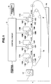
- Fig. 1 is a diagram showing the structure of the color printer according to the first embodiment.
- the color printer includes a printer engine 1, a control circuit 2 for controlling the operation of the printer engine 1, and an operation panel 3 for externally providing instructions to the color printer.
- the printer engine 1 includes developing units 11K (black), 11Y (yellow), 11M (magenta), 11C (cyan), LED heads 12K, 12Y, 12M, 12C, photosensitive drums 13K, 13Y, 13M, 13C, charging brushes 14K, 14Y, 14M, 14C, transfer units 15K, 15Y, 15M, 15C, a conveying belt 16, a fixing unit 17 and a sheet feeding cassette 18.
- the developing units 11K, 11Y, 11M and 11C include developing rollers 111K , 111Y, 111M and 111C, respectively.
- the developing units 11K, 11Y, 11M and 11C bear the toners of their corresponding colors and adhere the toners to the photosensitive drums 13K, 13Y, 13M and 13C via the developing rollers 111K, 111Y, 111M and 111C, respectively.
- the LED heads 12K, 12Y, 12M and 12C emit light in accordance with image data sent from the control circuit 2.
- the photosensitive drums 13K, 13Y, 13M and 13C are charged with electricity by the charging brushes 14K, 14Y, 14M and 14C, respectively, and are exposed to the light emitted from the LED heads 12K, 12Y, 12M and 13C.
- the toners are adhered via the developing rollers 111K, 111Y, 111M and 111C to those parts of the photosensitive drums 13K, 13Y, 13M and 13C which have been exposed to the light.
- the transfer units 15K, 15Y, 15M and 15C apply a predetermined voltage to the photosensitive drums 13K 13Y,13M and 13C through a sheet of paper P, thereby transferring the toners to the sheet of paper P from the photosensitive drums 13K, 13Y, 13M and 13C.
- the conveying belt 16 conveys, one by one, sheets of papers held in the sheet feeding cassette 18.
- the fixing unit 17 has a heater, which generates heat to fix the toners transferred by the transfer units 15K, 15Y, 15M and 15C to the sheet of paper P.
- the sheet feeding cassette 18 holds plural sheets of paper P.
- the control circuit 2 has a CPU 21, a ROM 22, a RAM 23, a font ROM 24, a video interfaces 25y, 25m, 25c, 25k, an operation panel interface 26, a parallel interface 27, a serial interface 28, a card interface 29, all being connected to each other via a bus.
- the CPU 21 executes a program stored in the ROM 22, performs various processing necessary to print images, and controls the individual internal parts of the control circuit 2.
- the CPU 21 generates a mask pattern (described later) in accordance with gradation information contained in print information sent from a host such as a personal computer through the parallel interface 27 or the serial interface 28, and stores the mask pattern in mask pattern areas 23ay, 23am, 23ac or 23ak of the RAM 23.
- the CPU 21 develops the corresponding image data in frame memories 23by, 23bm, 23bc and 23bk. Further, the CPU 21 controls the operations of the individual parts of the printer engine 1 via a drive circuit (not shown).
- the ROM 22 stores a processing program for the CPU 21, and has an area 22a for storing a threshold matrix used to generate a dithering mask pattern which will be described later.
- Fig. 3 shows an example of the threshold matrix.
- the threshold matrix is an 8 x 8 matrix, and each of the individual elements constituting the threshold matrix corresponds to one of the dots forming an image to be printed.
- the numerals shown in the individual elements of the threshold matrix indicate the order of priority in which the dots are set ON (the transfer of the toners) in accordance with the gradations in the original image input from the host.
- a plurality of threshold matrices are prepared each for one of the colors Y, M, C and K.
- the RAM 23 has the mask pattern areas 23ay, 23am 23ac and 23ak, the frame memories 23by, 23bm, 23bc and 23bk, a buffer area and a work area for the CPU 21.
- the buffer area stores the print information which is sent from the host through the parallel interface 27 or the serial interface 28 and which contains any character code and position information concerning an image to be printed, the gradation information specifying to the gradations in the image to be printed, etc.
- the mask pattern areas 23ay, 23am, 23ac and 23ak store the mask patterns created in accordance with the threshold matrices for the colors Y, M, C and K. Font patterns read out from the font ROM 24 in accordance with character codes, for example, are developed in the frame memories 23by, 23bm, 23bc and 23bk.
- the font ROM 24 stores the font patterns corresponding to the character codes.
- the video interfaces 25y, 25m, 25c and 25k are connected to the LED heads 12Y, 12M, 12C and 12K of the printer engine 1, respectively. Image data stored in the frame memories 23by, 23bm, 23bc and 23bk are sent to the LED heads 12Y, 12M, 12C and 12K through the video interfaces 25y, 25m, 25c and 25k.
- the operation panel interface 26 is connected to the operation panel 3.
- the parallel interface 27 and the serial interface 28 are to be connected to the host such as a personal computer.
- the card interface 29 is to be connected to a card such as a function expansion card inserted in a card slot (not shown).
- the operation panel 3 illustrated in Fig. 1 has switches like an environment setting switch, a mode setting switch and a reset switch. When a user operates a switch provided on the operation panel 3, a command is sent to the control circuit 2.
- the print information is sent from the host such as a personal computer through the parallel interface 27 or the serial interface 28, the print information is stored in the buffer area of the RAM 23.
- the CPU 21 Upon receiving the print information, the CPU 21 generates mask patterns of the number corresponding to the gradation information contained in the print information.
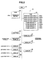
- Fig. 4 is a flowchart showing a process by which the CPU 21 of the color printer according to the first embodiment generates a mask pattern.
- the threshold values shown in the individual elements forming the threshold matrix are represented as t (x, y).
- the tone of color of each pixel in an image is expressed in an integral number equal to or greater than 0 (the integral numbers representing the tones of colors of the pixels will be hereinafter referred to as the tone numbers). The greater the tone numbers, the deeper the colors.
- the CPU 21 reads out, from that buffer area of the RAM 23 which stores the gradation information, the tone number specifying the tone of color of each pixel in the image to be printed, and substitutes the value obtained by subtracting 1 from the tone number for a variable G (step S12).
- the CPU 21 substitutes the value obtained by subtracting 1 from the tone number for the variable G in the step S12, it executes a process for creating mask patterns one in association with each of the values 0 to G of gradations "g" [loop 2 (steps S13 to S13')].
- the CPU 21 sequentially changes the values of x and y, and determines whether to set a dot ON (transfer a toner) or to set a dot OFF (transfer no toner) in regard to every combination of (x, y) [loop 3 (steps S14 and S14') and loop 4 (steps S15 and S15')].
- the CPU 21 performs the arithmetic operation shown below as formula (1), and determines whether the formula (1) is satisfied or not (step S16): t (x, y) ⁇ g ⁇ X ⁇ Y / G
- the CPU 21 determines in the step S16 that the formula (1) is not satisfied, it executes no processing and goes to the steps to be carried out as regards the next combination of (x, y) shown in the loops 3 and 4.
- the CPU 21 determines in the step 16 that the formula (1) is satisfied, it sets ON the dot specified by the coordinates (x, y) on a mask pattern to be created (step S17), and goes to the steps to be carried out as regards the next combination of (x, y) shown in the loops 3 and 4.
- the loops 3 and 4 terminate when the steps S16 and S17 have been executed in association with all combinations of (x, y).
- the loop 2 terminates when the loop 3 has been executed in association with all values of the gradations "g".
- the loop 1 terminates when the loop 2 has been executed in regard to all of the colors Y, M, C and K.
- the mask patterns for Y, M, C and K are created in the above-described manner, and are stored in the mask pattern areas 23ay, 23am, 23ac and 23ak. The number of mask patterns stored in each mask pattern area corresponds to the number of tones.
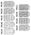
- the number of tones, which is designated by the gradation information contained in the print information, is nine.
- Mask patterns for only one color are shown in this example. However, mask patterns for the other colors are created as well.
- This threshold value does not satisfy the above relation, and therefore the dot specified by the coordinates (0, 1) is kept OFF. Similarly the processing within the loops 3 and 4 is all performed, as a result of which the mask pattern shown in Fig. 5B, where predetermined dots have been set ON, is created.
- Figs. 5C to 5I show the mask patterns created by the above-described process in the case of gradations "g" of 2 to G.
- mask pattern data corresponding to the tones specified by the color information is read out from the mask pattern areas 23ay, 23am, 23ac and 23ak, and AND operations are performed with respect to the image data and the corresponding dots in the mask patterns.
- the CPU 21 When 1-page image data has been developed in the frame memories 23by, 23bm, 23bc and 23bk, the CPU 21 reads out, for example, 1-line data from the frame memory 23bc storing the image data of the color C the toner of which is to be transferred first on a sheet of paper P, and outputs the read-out data as parallel data to the video interface 25c.
- the video interface 25c converts the parallel data to serial data, and sequentially outputs the serial data to the LED head 12C.
- the CPU 21 similarly processes the data of the color M.
- the CPU 21 also processes the data of the color Y as well.
- the CPU 21 processes the data of the color K as well.
- the CPU 21 similarly processes the next-line data of the color C.
- the LED heads 12C, 12M, 12Y and 12K radiate light onto their respective photosensitive drums 13C, 13M, 13Y and 13K in synchronization with each other, under the control of the CPU 21.
- the toners supplied from the developing units 11C, 11M, 11Y and 11K are adhered through the developing rollers 111C, 111M, 111Y and 111K to those parts of the photosensitive drums 13C, 13M, 13Y and 13K which are exposed to the light.
- the photosensitive drums 13C, 13M, 13Y and 13K are in synchronization with each other under the control of the CPU 21, and the toners of the individual colors C, M, Y and K are sequentially transferred to a sheet of paper P via the transfer units 15C, 15M, 15Y and 15K, whereby images in the colors C, M, Y and K are formed on the sheet of paper P with being superposed on one another, thus printing a color image on the sheet of paper P.
- the mask patterns for realizing halftones are created in accordance with a threshold matrix.
- the mask patterns need not be prestored in the ROM 22.
- the number of mask patterns to be created needs only be equal to the number of tones.
- a color printer which uses, as threshold matrices, two types of matrices which are a basic pattern matrix and an arrangement pattern matrix.
- the structure of the color printer according to the second embodiment is substantially the same as that of the first embodiment, except that a threshold matrix stored in the ROM 22 of the color printer of the second embodiment is different from that of the first embodiment.
- the number of dots forming the threshold matrix is variable.
- the print information sent from the host contains information (hereinafter referred to as the pixel information) indicating the number of dots forming a print image which is output from the printer and which corresponds to 1 pixel in the original image input from the host.
- the threshold matrix of the second embodiment will now be described.
- the threshold matrix is constituted by the basic pattern matrix shown in Fig. 6A and the arrangement pattern matrices shown in Figs. 6B to 6D.
- the basic pattern matrix is a basic-unit matrix forming the threshold matrix.
- Fig. 6A shows the case where the basic-unit matrix consists of 8 ⁇ 8 dots.
- the arrangement pattern matrices are used to create mask patterns based on that threshold matrix.
- Figs. 6B to 6D show the arrangement patterns to create mask patterns in the case where the number of vertical dots and the number of horizontal dots are quadrupled, trebled and doubled.
- the print information When the print information is supplied from a host such as a personal computer through the parallel interface 27 or the serial interface 28, the print information is stored in the buffer area of the RAM 23. Upon reception of the print information, the CPU 21 creates the threshold matrix according to the pixel information contained in the print information.
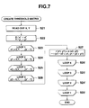
- Fig. 7 is a flowchart showing a threshold matrix creating process executed by the CPU 21 of the color printer according to the second embodiment.
- the number of vertical dots and the number of horizontal dots in the basic unit of the mask patterns are given as x' and y', respectively.
- the threshold values shown in the elements of the threshold matrix are expressed as s(x1, y1).
- the number of vertical dots and the number of horizontal dots in a print image, which corresponds to 1 pixel in the original image, are given as X and Y, respectively, and are specified by the print information.
- the arrangement pattern matrix to be used is determined by x'' and y'' obtained in the manner which will be explained later.
- the numerals shown in the individual elements of the threshold matrix are represented as r (x2, y2).
- the CPU 21 reads out, from that buffer area of the RAM 23 which stores the pixel information, the number X of vertical dots and the number Y of horizontal dots of the print image to be reproduced from 1 pixel in the original image (step S21).
- the CPU 21 divides X by x', and substitutes the result of the division for x''.
- the CPU 21 divides Y by y'', and substitutes the result of the division for y'' (step S22).
- An arrangement pattern matrix to be used to create the threshold matrix is determined in accordance with the result of the calculations in the step S22.
- the CPU 21 executes the processing within four loops 1 to 4.
- the value x1 representing an x coordinate on the basic pattern matrix is changed from 0 to (x'-1) (steps S23 and S23').
- the value y1 representing a y coordinate on the basic pattern matrix is changed from 0 to (y'-1) (steps S24 and S24').
- the value x2 representing an x coordinate on the basic pattern matrix is changed from 0 to (x''-1) (step S25 and S25').
- the value x2 representing a y coordinate on the basic pattern matrix is changed from 0 to (y''-1) (steps S26 and S26').
- the CPU 21 executes the processing shown by the formula (2). Specifically, the CPU 21 obtains the numerals in the individual elements of the threshold matrix to be created (step S27). r (x1, y1) + s (x2, y2) ⁇ (x1 ⁇ x2 + x2, y1 ⁇ y2 + y2)
- the threshold matrix is created as a result of the processing within the four loops 1 to 4 being finished.
- the creation of the threshold matrix is performed in association with each of the colors Y, M, C and K.
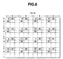
- Fig. 8 shows an example of the threshold matrix created by the above-described process.
- the threshold matrix in this example is one created using the basic pattern matrix shown in Fig. 6A and the arrangement patter matrix shown in Fig. 6B.
- the threshold matrix can be created using the basic pattern matrix and an arrangement pattern matrix, and the mask patterns can be created utilizing the threshold matrix as created.
- the amount of data prestored in the ROM 22 is smaller than in the case of storing the threshold matrix itself in the ROM 22.
- a color printer which can control the number of tones of colors of the pixels in the image to be printed, in accordance with the capacity of a mask pattern tone area 13a which can be reserved in the RAM 13.
- the structure of the color printer according to the third embodiment is substantially the same as that of the first embodiment.
- the print information is sent from a host such as a personal computer through the parallel interface 27 or the serial interface 28, the print information is stored in the buffer area of the RAM 23.
- the CPU 21 creates mask patterns of the number according to the gradation information contained in the print information.
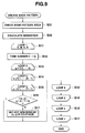
- Fig. 7 is a flowchart showing a mask pattern creating process executed by the CPU 21 of the color printer of the third embodiment.
- the CPU 21 checks the capacities of areas which can be reserved in the RAM 23 as the mask pattern areas 23ay, 23am, 23ac and 23ak (step S31).
- the CPU 21 determines the number of mask patterns which can be stored in the areas capable of being reserved as the mask pattern areas 23ay, 23am, 23ac and 23ck, i.e., the number of tones of colors of the pixels in the image to be printed (step S32).
- the processing carried out thereafter is the same as that of the first embodiment, except that the number of tones calculated in the step S32 is used in the step S12.
- the number of tones is determined in accordance with the capacities of the areas which can be reserved as the mask pattern areas 23ay, 23am, 23ac and 23ak. This enables the efficient use of the RAM 23.
- a color printer which determines the number of "ON" dots in consideration of the blur of the toners which occurs when the toners are transferred to a sheet of paper and wherein apparent variations in the thickness of an image describe a curve in a graph in accordance with the gradations in the image.
- the structure of the color printer of the fourth embodiment is substantially the same as that of the first embodiment, except that in the case of the color printer of the fourth embodiment, the toners transferred to a sheet of paper blur such that the pattern of an image which the toners have formed on the sheet of paper expands.
- the toners are fixed to the sheet of paper by the fixing unit 17 in the state that the pattern formed by the toners has thus expanded.
- the ratio of the area of the pattern at the time of the transfer of the toners to the area of the pattern at the time of the fixture of the toners will be hereinafter referred to as the toner blur ratio.
- the thickness of any pixel in the image to be printed varies almost linearly in accordance with the number of "ON" dots until the number of "ON” dots reaches 50%.
- the blur ratio B can be obtained by measuring the image thickness C when the ratio of the number of "ON" dots to the total number of dots is 50%.
- the blur ratio B is 150% in the case where the image thickness C is 75% when the ratio of the number of "ON" dots to the total number of dots is 50%.
- the print information is sent from a host such as a personal computer through the parallel interface 27 or the serial interface 28, the print information is stored in the buffer area of the RAM 23.
- the CPU 21 creates mask patterns of the number according to the gradation information contained in the print information.
- Fig. 10 is a flowchart showing a mask pattern creating process executed by the CPU 21 of the color printer of to the fourth embodiment.
- the mask patterns of the number according to the gradation information are created in association with each of the colors Y, M, C and K, based on a threshold matrix stored in the ROM 22 [loop 1 (steps S41 and S41')].
- the CPU 21 reads out, from that buffer area of the RAM 23 which stores the gradation information, the tone number specifying the tone of color of each pixel in the image to be printed, and substitutes the value obtained by subtracting 1 from the tone number for a variable G (step S42).
- the CPU 21 divides a gradation or variable "g" by G, thereby calculating the target image thickness C, and determines whether the calculated thickness C is greater or not greater than 0.5 (50%) (step S44).
- the CPU 21 determines in the step S44 that the thickness C is equal to or less than 0.5, it performs the arithmetic operation shown by the formula (4), thereby to obtain the number "d" of ON dots (step 545).
- the CPU 21 determines in the step S44 that the thickness C is greater than 0.5, it performs the arithmetic operation shown by the formula (5), thereby to obtain the number "d" of ON dots (step S46).
- the CPU 21 sequentially changes the values of x and y, and determines whether to set a dot ON (transfer a toner) or to set a dot OFF (transfer no toner) in regard to every combination of (x, y) [loop 3 (steps S47 and S47') and loop 4 (steps S48 and S48')].
- the CPU 21 determines whether each of the numerals t (x, y) in the individual elements forming the threshold matrix is greater or not greater than the number "d" of ON dots obtained in the step S45 or S46 (step S49).
- the CPU 21 determines in the step S49 that t (x, y) is greater than the number "d" of ON dots, it executes no processing and goes to the steps to be carried out as regards the next combination of (x, y) shown in the loops 3 and 4.
- the CPU 21 determines in the step 49 that t (x, y) is equal to or less than the number "d" of ON dots, it sets ON the dot specified by the coordinates (x, y) on a mask pattern to be created (step S50), and goes to the steps to be carried out as regards the next combination of (x, y) shown in the loops 3 and 4.
- the loops 3 and 4 terminate when the steps S49 and S50 have been executed in association with all combinations of (x, y).
- the loop 2 terminates when the loop 3 has been executed in association with all values of the gradations "g".
- the loop 1 terminates when the loop 2 has been executed in regard to all of the colors Y, M, C and K.
- the mask patterns for Y, M, C and K are created in the above-described manner, and are stored in the mask pattern areas 23ay, 23am, 23ac and 23ak.
- Fig. 11A shows an example of the relationship between the tone of color (expressed in the gradation ratio g/G herein) of a pixel in the image to be printed and the number "d" of ON dots according to the above-described process.
- Fig. 11B shows an example of the relationship between the gradation ratio g/G and the thickness C of a pixel in a printed image according to the above-described process.
- the number "d" of ON dots is varied non-linearly, as seen in the graph of Fig. 11A wherein the line showing the relationship bends at the point corresponding to a gradation ratio of 50%.
- the thickness C varies almost linearly as shown in the graph of Fig.
- Fig. 12B Shown in Fig. 12B for the sake of comparison is the relationship between the gradation ratio r/G and the thickness C in the case (Fig. 12A) where the number "d" of ON dots is varied linearly in relation to the gradation ratio g/G.
- the thickness C varies non-linearly before and after the point corresponding to a gradation ratio of 50%.
- the number "d" of ON dots is determined in consideration of the toner blur ratio so that that the gradations which most approximate to the color tone variations in an image to be printed can be attained in the image as printed.
- a color printer which can perform dithering through the use of a plurality of types of dither patterns (mask patterns), which are, for example, center-type dither patterns in which the dots are sequentially set ON from the centers of the pixels, and dispersion-type dither patterns in which the dots which are set ON dispersedly as in the case of the first to fourth embodiments described above.
- dither patterns are, for example, center-type dither patterns in which the dots are sequentially set ON from the centers of the pixels, and dispersion-type dither patterns in which the dots which are set ON dispersedly as in the case of the first to fourth embodiments described above.
- the structure of the color printer of the fifth embodiment is substantially the same as that of the first embodiment, except that the ROM 22 of the color printer according to the fifth embodiment stores both a threshold matrix to create center-type dither patterns and a threshold matrix to create dispersion-type dither patterns.
- the ROM 22 also stores the toner blur ratios corresponding to the individual dither patterns.
- the print information sent from a host connected to the color printer specifies whether to represent gradations through the use of the center-type dither patterns or whether to represent gradations through the use of the dispersion-type dither patterns.
- the print information is sent from the host such as a personal computer through the parallel interface 27 or the serial interface 28, the print information is stored in the buffer area of the RAM 23.
- the CPU 21 creates mask patterns of the number corresponding to the gradation information contained in the print information.
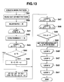
- Fig. 13 is a flowchart showing a mask pattern creating process executed by the CPU 21 of the color printer according to the fifth embodiment.
- the CPU 21 reads out, from that buffer area of the RAM 23 which stores the print information, data specifying the type (the center-type or dispersion-type) of a dither pattern a dither pattern to be used to print pixels which form an image in a gradation of colors (step S51).
- the CPU 21 reads out from the ROM 22 the toner blur ratio corresponding to the above dither pattern, and substitutes the blue ratio for a valuable B (step S52).
- the steps carried out thereafter are substantially the same as the steps S41 to S50 explained in the fourth embodiment.
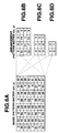
- Fig. 14A exemplifies the relationship between the tone of color (expressed in the gradation ratio g/G herein) of a pixel in an image to be printed and the thickness C of a pixel in a printed image when printing is performed using a center-type dither pattern according to the above-described process.
- the toner blur ratio is 150%, for example, and the thickness C varies almost linearly.
- Fig. 14B exemplifies the relationship between the tone of color (the gradation ratio g/G) of a pixel in an image to be printed and the thickness C of a pixel in a printed image when printing is performed using a dispersion-type dither pattern under the condition wherein the toner blur ratio is150%.
- the thickness C varies non-linearly before and after the point corresponding to a gradation ratio of 50%.
- Fig. 14C exemplifies the relationship between the tone of color (the gradation ratio g/G) of a pixel in an image to be printed and the thickness C of a pixel in a printed image when printing is performed using a dispersion-type dither pattern under the condition wherein the toner blur ratio is 130%.
- the thickness C varies almost linearly.
- the toner blur ratio is adjusted in accordance with a difference between the dither patterns so that the gradations which most approximate to the color tone variations in an image to be printed can be attained in the image as printed, whichever type of dither pattern is employed.
- the above-described embodiments are directed to color printers which print a color image on a sheet of paper by printing monochrome images in four colors of yellow (Y), magenta (M), cyan (C) and black (K) so as to be superposed on one another.
- the number of monochrome images which are superposed on one another to print a color image is arbitrary.
- the colors of the monochrome images superposed on one another are also not limited to four colors of yellow (Y), magenta (M), cyan (c) and black (K).
- the present invention is applicable also to a printer which prints an image in a single color, insofar as halftones are represented through dithering.
- electrophotographic printers which print a color image on a sheet of paper through the use of toners in four colors of yellow (Y), magenta (M), cyan (c) and black (K) by printing images in the individual colors so as to be superposed on one another.
- Y yellow
- M magenta
- c cyan
- K black
- the present invention is applicable also to other types of printers like an ink-jet printer and a fusion-type thermal transfer printer.
- a dithering method wherein dithering is performed through the use of mask patterns creased based on a threshold matrix is applied to the printers.
- the dithering method of the present invention is applicable also to the case where an image is output to an image outputting apparatus of another type.
Abstract
Description
→ (x1 × x2 + x2, y1 × y2 + y2)
Claims (13)
- A dithering method for masking image data with a mask pattern conforming to a gradation corresponding to said image data, and developing the masked image data in a frame memory (23by, 23bm, 23bc, 23bk), characterized by comprising:a matrix storing step of storing in a first memory (22a) a matrix of elements serving as pieces of order information;a mask pattern creating step of determining mask locations in accordance with the pieces of order information in said matrix and creating a plurality of mask patterns each conforming to one of gradations in an image to be printed; anda dithering step of masking said image data by using, of the mask patterns created by said mask pattern creating step, the mask pattern conforming to the gradation corresponding to said image data.
- The dithering method according to claim 1,
characterized in that:said dithering method further comprises a mask pattern storing step of storing the mask patterns created by said mask pattern creating step in a second memory (23ay, 23am, 23ac, 23ak); andof the mask patterns stored in said second memory (23ay, 23am, 23ac, 23ak) by said mask pattern storing step, the mask pattern conforming to the gradation corresponding to said image data is used to mask said image data in said dithering step. - The dithering method according to claim 1,
characterized in that:said first memory (22a) is a nonvolatile storage medium; andsaid matrix storing step is a step of prestoring said matrix in said nonvolatile storage medium. - The dithering method according to claim 1,
characterized in that:said matrix includes a basic matrix having elements serving as pieces of order information and an arrangement matrix having elements serving as pieces of order information specifying an order in which the elements of said basic matrix are arranged; andsaid mask pattern creating step is a step of determining the mask locations in accordance with the pieces of order information in said basic matrix and the pieces of arrangement information in said arrangement matrix, in order to create said mask patterns. - The dithering method according to claim 2,
characterized by further comprising:said mask pattern creating step is a step of creating mask patterns of the number determined by said gradation number determining step.a checking step of checking, in said mask pattern storing step, a storage capacity of said second memory (23ay, 23am, 23ac, 23ak) which can store said mask patterns, anda gradation number determining step of determining the number of gradations which corresponds to the number of mask patterns said second memory can store with the storage capacity checked by said checking step; and - A printing apparatus comprising mask means (21) for masking image data with a mask pattern conforming to a gradation corresponding to said image data, a frame memory (23by, 23bm, 23bc, 23bk) in which the image data masked by said mask means (21) is developed, and printing means for printing on a sheetlike recording medium (P) an image corresponding to the image data developed in said frame memory (23by, 23bm, 23bc, 23bk), said printing apparatus characterized by further comprising:a first memory (22a) for storing a matrix of elements serving as pieces of order information;mask pattern creating means (21) for determining mask locations in accordance with the pieces of order information in said matrix stored in said first memory (22a) and creating a plurality of mask patterns each conforming to one of gradations in an image to be printed; anda second memory (23ay, 23am, 23ac, 23ak) for storing the mask patterns created by said mask pattern creating means (21);said masking means (21) masking said image data by using, of the mask patterns stored in said second memory (23ay, 23am, 23ac, 23ak), the mask pattern conforming to the gradation corresponding to said image data.
- The printing apparatus according to claim 6,
characterized in that:said frame memory (23by, 23bm, 23bc, 23bk) includes a plurality of frame memories in which image data items showing different colors are developed;said first memory (22a) stores, in association with said different colors, a plurality of matrices each having elements serving as pieces of information;said mask pattern creating means (21) creates a plurality of mask patterns for each of said different colors by using said plurality of matrices stored in said first memory (22a);said mask means (21) masks each of said image data items developed in said plurality of frame memories with the mask patterns created for the color shown by each said image data item; andsaid printing means (1) prints a plurality of images on said recording medium (P) in a state of being superposed on one another, said plurality of images corresponding to said image data items developed in said plurality of frame memories and which show said different colors. - The printing apparatus according to claim 6,
characterized in that:said matrix includes a basic matrix having elements serving as pieces of order information and an arrangement matrix having elements serving as pieces of order information specifying an order in which the elements of said basic matrix are arranged; andsaid mask pattern creating means determines the mask locations in accordance with the pieces of order information in said basic matrix and the pieces of arrangement information in said arrangement matrix, in order to create said mask patterns. - The printing apparatus according to claim 8,
characterized in that:said image data input from said host apparatus represent pixels, each of which corresponds to some of dots forming the printed image;said printing apparatus further comprises discriminating means (21) for discriminating the number of dots corresponding to one of said pixels; andsaid basic matrix corresponds to one of said pixels. - The printing apparatus according to claim 6, characterized by further comprising:said mask pattern creating means (21) creates mask patterns of the number determined by said gradation number determining means.checking means (21) for checking a storage capacity of said second memory (23ay, 23am, 23ac, 23ak), andgradation number determining means (21) for determining the number of gradations which corresponds to the number of mask patterns said second memory can store with the storage capacity checked by said checking means; and
- The printing apparatus according to claim 6, characterized in that said mask pattern creating means (21) includes adjusting means for adjusting said mask patterns created so that the image which is printed on said recording medium (P) conforms in gradation to the image to be printed.
- The printing apparatus according to claim 11, characterized in that:said first memory (22a) stores a plurality of matrices and pieces of adjustment information in association with each other, said plurality of matrices being different from each other in an arrangement of elements, and said pieces of adjustment information being used for adjusting said mask patterns so that the image which is printed on said recording medium (P) conforms in gradation to the image to be printed; andsaid adjusting means adjusts said mask patterns in accordance with said pieces of adjustment information.
- The printing apparatus according to claim 6, characterized in that:said first memory (22a) is a nonvolatile storage medium; andsaid second memory (23ay, 23am, 23ac, 23ak) is a volatile storage medium.
Applications Claiming Priority (3)
| Application Number | Priority Date | Filing Date | Title |
|---|---|---|---|
| JP8331985A JPH10166664A (en) | 1996-12-12 | 1996-12-12 | Color printer |
| JP33198596 | 1996-12-12 | ||
| JP331985/96 | 1996-12-12 |
Publications (3)
| Publication Number | Publication Date |
|---|---|
| EP0848348A2 true EP0848348A2 (en) | 1998-06-17 |
| EP0848348A3 EP0848348A3 (en) | 2002-10-02 |
| EP0848348B1 EP0848348B1 (en) | 2006-08-02 |
Family
ID=18249860
Family Applications (1)
| Application Number | Title | Priority Date | Filing Date |
|---|---|---|---|
| EP97403027A Expired - Lifetime EP0848348B1 (en) | 1996-12-12 | 1997-12-12 | Dither method and printing apparatus |
Country Status (5)
| Country | Link |
|---|---|
| US (1) | US6111658A (en) |
| EP (1) | EP0848348B1 (en) |
| JP (1) | JPH10166664A (en) |
| DE (1) | DE69736421T2 (en) |
| HK (1) | HK1012515A1 (en) |
Cited By (1)
| Publication number | Priority date | Publication date | Assignee | Title |
|---|---|---|---|---|
| WO2009023086A2 (en) * | 2007-08-03 | 2009-02-19 | Eastman Kodak Company | Stochastic halftone images based on screening parameters |
Families Citing this family (17)
| Publication number | Priority date | Publication date | Assignee | Title |
|---|---|---|---|---|
| US6956670B1 (en) | 2000-10-24 | 2005-10-18 | International Business Machines Corporation | Method, system, program, and data structures for halftoning with line screens having different lines per inch (LPI) |
| US7330291B2 (en) * | 2001-03-02 | 2008-02-12 | Dai Nippon Printing Co., Ltd. | Dither mask creating method and creating device |
| US6765695B2 (en) | 2001-09-12 | 2004-07-20 | Seiko Epson Corporation | Color processing architecture and algorithms for color laser printers |
| JP4016629B2 (en) * | 2001-10-11 | 2007-12-05 | 富士ゼロックス株式会社 | Gradation display method |
| JP4150206B2 (en) * | 2001-10-29 | 2008-09-17 | 富士フイルム株式会社 | Halftone threshold data creation method |
| JP2004336163A (en) * | 2003-04-30 | 2004-11-25 | Minolta Co Ltd | Apparatus, method, and program for image processing |
| US8067214B2 (en) | 2007-03-16 | 2011-11-29 | Genomatica, Inc. | Compositions and methods for the biosynthesis of 1,4-butanediol and its precursors |
| US7947483B2 (en) | 2007-08-10 | 2011-05-24 | Genomatica, Inc. | Methods and organisms for the growth-coupled production of 1,4-butanediol |
| CA2735883C (en) | 2008-09-10 | 2020-05-05 | Genomatica, Inc. | Microorganisms for the production of 1,4-butanediol |
| US8129169B2 (en) | 2009-06-04 | 2012-03-06 | Genomatica, Inc. | Microorganisms for the production of 1,4-butanediol and related methods |
| PL2438036T3 (en) * | 2009-06-04 | 2017-09-29 | Genomatica, Inc. | Process of separating components of a fermentation broth |
| US8377666B2 (en) * | 2009-10-13 | 2013-02-19 | Genomatica, Inc. | Microorganisms for the production of 1,4-butanediol, 4-hydroxybutanal, 4-hydroxybutyryl-coa, putrescine and related compounds, and methods related thereto |
| WO2011066076A1 (en) | 2009-11-25 | 2011-06-03 | Genomatica, Inc. | Microorganisms and methods for the coproduction of 1,4-butanediol and gamma-butyrolactone |
| US8637286B2 (en) | 2010-02-23 | 2014-01-28 | Genomatica, Inc. | Methods for increasing product yields |
| US8048661B2 (en) | 2010-02-23 | 2011-11-01 | Genomatica, Inc. | Microbial organisms comprising exogenous nucleic acids encoding reductive TCA pathway enzymes |
| CN111705028A (en) | 2012-06-04 | 2020-09-25 | 基因组股份公司 | Microorganisms and methods for making 4-hydroxybutyrate, 1, 4-butanediol, and related compounds |
| JP6907034B2 (en) | 2017-06-08 | 2021-07-21 | キヤノン株式会社 | Image processing equipment, image processing methods and programs |
Citations (3)
| Publication number | Priority date | Publication date | Assignee | Title |
|---|---|---|---|---|
| EP0444290A2 (en) * | 1990-02-26 | 1991-09-04 | Hewlett-Packard Company | Method and system for reproducing monochromatic and color images using ordered dither and error diffusion |
| EP0580376A1 (en) * | 1992-07-23 | 1994-01-26 | Xerox Corporation | Image processing method to reduce marking material coverage in printing processes |
| EP0710006A2 (en) * | 1994-10-28 | 1996-05-01 | Nec Corporation | Image forming apparatus capable of producing a pseudo half-tone image by using dither patterns |
Family Cites Families (7)
| Publication number | Priority date | Publication date | Assignee | Title |
|---|---|---|---|---|
| US4974067A (en) * | 1986-06-06 | 1990-11-27 | Ricoh Company, Ltd. | Multi-step-digital color image reproducing method and apparatus |
| US5177623A (en) * | 1988-04-07 | 1993-01-05 | Minolta Camera Kabushiki Kaisha | Image processing apparatus and method |
| JPH0491966A (en) * | 1990-08-08 | 1992-03-25 | Canon Inc | Printer |
| JPH06291994A (en) * | 1992-08-10 | 1994-10-18 | Ricoh Co Ltd | Method and unit for processing picture |
| JPH06253134A (en) * | 1993-02-26 | 1994-09-09 | Toshiba Corp | Picture processing device |
| US5953459A (en) * | 1996-02-23 | 1999-09-14 | Brother Kogyo Kabushiki Kaisha | Dither matrix producing method |
| US5761347A (en) * | 1996-09-30 | 1998-06-02 | Apple Computer, Inc. | Method and system for halftoning by tiling subsets of a threshold array over portions of an image |
-
1996
- 1996-12-12 JP JP8331985A patent/JPH10166664A/en active Pending
-
1997
- 1997-12-08 US US08/986,808 patent/US6111658A/en not_active Expired - Lifetime
- 1997-12-12 EP EP97403027A patent/EP0848348B1/en not_active Expired - Lifetime
- 1997-12-12 DE DE69736421T patent/DE69736421T2/en not_active Expired - Lifetime
-
1998
- 1998-12-17 HK HK98113881A patent/HK1012515A1/en not_active IP Right Cessation
Patent Citations (3)
| Publication number | Priority date | Publication date | Assignee | Title |
|---|---|---|---|---|
| EP0444290A2 (en) * | 1990-02-26 | 1991-09-04 | Hewlett-Packard Company | Method and system for reproducing monochromatic and color images using ordered dither and error diffusion |
| EP0580376A1 (en) * | 1992-07-23 | 1994-01-26 | Xerox Corporation | Image processing method to reduce marking material coverage in printing processes |
| EP0710006A2 (en) * | 1994-10-28 | 1996-05-01 | Nec Corporation | Image forming apparatus capable of producing a pseudo half-tone image by using dither patterns |
Cited By (2)
| Publication number | Priority date | Publication date | Assignee | Title |
|---|---|---|---|---|
| WO2009023086A2 (en) * | 2007-08-03 | 2009-02-19 | Eastman Kodak Company | Stochastic halftone images based on screening parameters |
| WO2009023086A3 (en) * | 2007-08-03 | 2009-05-28 | Eastman Kodak Co | Stochastic halftone images based on screening parameters |
Also Published As
| Publication number | Publication date |
|---|---|
| JPH10166664A (en) | 1998-06-23 |
| HK1012515A1 (en) | 1999-08-06 |
| EP0848348B1 (en) | 2006-08-02 |
| DE69736421D1 (en) | 2006-09-14 |
| US6111658A (en) | 2000-08-29 |
| DE69736421T2 (en) | 2007-03-29 |
| EP0848348A3 (en) | 2002-10-02 |
Similar Documents
| Publication | Publication Date | Title |
|---|---|---|
| US6111658A (en) | Dither method and printing apparatus | |
| EP1900190B1 (en) | Image processing apparatus and method controlling the amount of transparent ink for recording | |
| EP0892544B1 (en) | Image processing apparatus and method and storage medium | |
| US7626741B2 (en) | Image processing method and apparatus thereof | |
| US7839537B2 (en) | Method and apparatus for multi-color printing using a rosette or diamond halftone screen for one or more of the colors | |
| US6160968A (en) | Printing method and image processing method for performing printing during which calibration of printing apparatus is executed | |
| WO2005112431A1 (en) | Hybrid dot-line halftone composite screens | |
| KR20060119820A (en) | Color printing | |
| JP2005295333A (en) | Apparatus and method for image forming, and program | |
| US6754455B2 (en) | Image forming apparatus and developer supply method therefor, and image processing board | |
| JP4115294B2 (en) | Image processing apparatus and method | |
| JP4472957B2 (en) | Image forming apparatus and image forming method | |
| JP2008302648A (en) | Image forming device | |
| US6271930B1 (en) | Image processing apparatus and method, and storage medium | |
| US7315320B2 (en) | Optical writing system and method, and image forming apparatus receiving an external parameter | |
| JPH10304176A (en) | Image processing unit, method and storage medium | |
| US5854689A (en) | Image processing apparatus and method for performing smoothing processing for each of different colors | |
| EP3617805B1 (en) | Image forming apparatus, method of controlling the same, and storage medium | |
| JP2017044883A (en) | Image forming apparatus and image forming method | |
| JPH1141447A (en) | Image processor, image processing method and recording medium | |
| JPH1141446A (en) | Device and method for processing image and recording medium | |
| US20090109456A1 (en) | Image Forming Apparatus, Image Forming Method, and Computer Readable Medium Recording a Printing Data Generation Program | |
| US20070286623A1 (en) | Image forming apparatus, control method for image forming apparatus and storage medium storing control program | |
| JPH10243127A (en) | Image processor and method therefor | |
| JP3894452B2 (en) | Color printer and color image printing method |
Legal Events
| Date | Code | Title | Description |
|---|---|---|---|
| PUAI | Public reference made under article 153(3) epc to a published international application that has entered the european phase |
Free format text: ORIGINAL CODE: 0009012 |
|
| AK | Designated contracting states |
Kind code of ref document: A2 Designated state(s): AT BE CH DE DK ES FI FR GB GR IE IT LI LU MC NL PT SE |
|
| AX | Request for extension of the european patent |
Free format text: AL;LT;LV;MK;RO;SI |
|
| PUAL | Search report despatched |
Free format text: ORIGINAL CODE: 0009013 |
|
| AK | Designated contracting states |
Kind code of ref document: A3 Designated state(s): AT BE CH DE DK ES FI FR GB GR IE IT LI LU MC NL PT SE |
|
| AX | Request for extension of the european patent |
Free format text: AL;LT;LV;MK;RO;SI |
|
| RIC1 | Information provided on ipc code assigned before grant |
Free format text: 7G 06K 15/02 A, 7G 06K 15/10 B, 7H 04N 1/40 B |
|
| 17P | Request for examination filed |
Effective date: 20030325 |
|
| AKX | Designation fees paid |
Designated state(s): DE FR GB |
|
| 17Q | First examination report despatched |
Effective date: 20040209 |
|
| GRAP | Despatch of communication of intention to grant a patent |
Free format text: ORIGINAL CODE: EPIDOSNIGR1 |
|
| GRAS | Grant fee paid |
Free format text: ORIGINAL CODE: EPIDOSNIGR3 |
|
| GRAA | (expected) grant |
Free format text: ORIGINAL CODE: 0009210 |
|
| AK | Designated contracting states |
Kind code of ref document: B1 Designated state(s): DE FR GB |
|
| REG | Reference to a national code |
Ref country code: GB Ref legal event code: FG4D |
|
| REF | Corresponds to: |
Ref document number: 69736421 Country of ref document: DE Date of ref document: 20060914 Kind code of ref document: P |
|
| REG | Reference to a national code |
Ref country code: HK Ref legal event code: GR Ref document number: 1012515 Country of ref document: HK |
|
| ET | Fr: translation filed | ||
| PLBE | No opposition filed within time limit |
Free format text: ORIGINAL CODE: 0009261 |
|
| STAA | Information on the status of an ep patent application or granted ep patent |
Free format text: STATUS: NO OPPOSITION FILED WITHIN TIME LIMIT |
|
| 26N | No opposition filed |
Effective date: 20070503 |
|
| PGFP | Annual fee paid to national office [announced via postgrant information from national office to epo] |
Ref country code: DE Payment date: 20141211 Year of fee payment: 18 Ref country code: GB Payment date: 20141219 Year of fee payment: 18 |
|
| PGFP | Annual fee paid to national office [announced via postgrant information from national office to epo] |
Ref country code: FR Payment date: 20141219 Year of fee payment: 18 |
|
| REG | Reference to a national code |
Ref country code: DE Ref legal event code: R119 Ref document number: 69736421 Country of ref document: DE |
|
| GBPC | Gb: european patent ceased through non-payment of renewal fee |
Effective date: 20151212 |
|
| REG | Reference to a national code |
Ref country code: FR Ref legal event code: ST Effective date: 20160831 |
|
| PG25 | Lapsed in a contracting state [announced via postgrant information from national office to epo] |
Ref country code: DE Free format text: LAPSE BECAUSE OF NON-PAYMENT OF DUE FEES Effective date: 20160701 Ref country code: GB Free format text: LAPSE BECAUSE OF NON-PAYMENT OF DUE FEES Effective date: 20151212 |
|
| PG25 | Lapsed in a contracting state [announced via postgrant information from national office to epo] |
Ref country code: FR Free format text: LAPSE BECAUSE OF NON-PAYMENT OF DUE FEES Effective date: 20151231 |