EP0848124A2 - Lock with latch and dead bolt - Google Patents
Lock with latch and dead bolt Download PDFInfo
- Publication number
- EP0848124A2 EP0848124A2 EP97118684A EP97118684A EP0848124A2 EP 0848124 A2 EP0848124 A2 EP 0848124A2 EP 97118684 A EP97118684 A EP 97118684A EP 97118684 A EP97118684 A EP 97118684A EP 0848124 A2 EP0848124 A2 EP 0848124A2
- Authority
- EP
- European Patent Office
- Prior art keywords
- nut
- lock
- arm
- lever
- bolt
- Prior art date
- Legal status (The legal status is an assumption and is not a legal conclusion. Google has not performed a legal analysis and makes no representation as to the accuracy of the status listed.)
- Granted
Links
Images


Classifications
-
- E—FIXED CONSTRUCTIONS
- E05—LOCKS; KEYS; WINDOW OR DOOR FITTINGS; SAFES
- E05B—LOCKS; ACCESSORIES THEREFOR; HANDCUFFS
- E05B59/00—Locks with latches separate from the lock-bolts or with a plurality of latches or lock-bolts
-
- E—FIXED CONSTRUCTIONS
- E05—LOCKS; KEYS; WINDOW OR DOOR FITTINGS; SAFES
- E05B—LOCKS; ACCESSORIES THEREFOR; HANDCUFFS
- E05B63/00—Locks or fastenings with special structural characteristics
- E05B63/16—Locks or fastenings with special structural characteristics with the handles on opposite sides moving independently
-
- E—FIXED CONSTRUCTIONS
- E05—LOCKS; KEYS; WINDOW OR DOOR FITTINGS; SAFES
- E05B—LOCKS; ACCESSORIES THEREFOR; HANDCUFFS
- E05B65/00—Locks or fastenings for special use
- E05B65/10—Locks or fastenings for special use for panic or emergency doors
- E05B65/1086—Locks with panic function, e.g. allowing opening from the inside without a ley even when locked from the outside
-
- E—FIXED CONSTRUCTIONS
- E05—LOCKS; KEYS; WINDOW OR DOOR FITTINGS; SAFES
- E05C—BOLTS OR FASTENING DEVICES FOR WINGS, SPECIALLY FOR DOORS OR WINDOWS
- E05C9/00—Arrangements of simultaneously actuated bolts or other securing devices at well-separated positions on the same wing
- E05C9/02—Arrangements of simultaneously actuated bolts or other securing devices at well-separated positions on the same wing with one sliding bar for fastening when moved in one direction and unfastening when moved in opposite direction; with two sliding bars moved in the same direction when fastening or unfastening
- E05C9/026—Arrangements of simultaneously actuated bolts or other securing devices at well-separated positions on the same wing with one sliding bar for fastening when moved in one direction and unfastening when moved in opposite direction; with two sliding bars moved in the same direction when fastening or unfastening comprising key-operated locks, e.g. a lock cylinder to drive auxiliary deadbolts or latch bolts
Definitions
- the invention relates to a lock with nut actuated Latch and key-operated bolt, the pre-closed Bolt together with the latch by nut actuation is retractable and the associated with the bolt Guard locking from a swivel arm-controlled lever arm is excavated.
- a castle of the type in question is known from DE-OS 24 33 322, wherein the nut is molded onto it Swivel arm trained.
- the latter owns one Lock housing protruding drive pin for the drive one lying on the outside of the lock housing Connecting rod.
- the lock can be used Trap and bolt in a panic situation Lever actuation can be opened.
- the Swiveling the nut on the one hand the drive rod in their Unlocked position moved.
- the Swivel arm a lever arm that raises the guard locking. Then the swivel arm delays the time another lever pivots, which locks the bolt concludes.
- the object of the invention is based on the object a generic lock of simpler, more compact and to specify a structure that is favorable in terms of locking technology.
- the drive rod connecting slide is on the swivel arm which in turn moves the bolt closes after the guard locking is released beforehand.
- the nut, swivel arm and lever arm can be spatially tightly packed in a stack on top of each other in the lock housing accommodate so that the lock with little Backset can be created.
- it is between Nut and lever arm mounted swivel arm with a control cam equipped, which when the Swivel arm, caused by nut rotation, a nose acted on the lever arm, pivoted and the guard locks out.
- the swivel arm driven in opposite directions to the nut rotation. Farther the control cam is forked through an incision.
- One cam tine acts on the closed one Position and the other cam tine in the pre-closed Lock position the nose of the lever arm connected with the fact that the guard locking interlock to the bar is raised. Since the latter over the slot / pin control with the connecting rod connecting slide coupled, takes place along with a displacement of the connecting rod connecting slide closing the bolt, be it in the closing position or in the closed position. To this Purpose is in the area of the control cam slot open on the edge, into which the pin of the connecting rod connecting slide engages with clutch. So serves the control cam not only for lifting the lever arm, but also contains the slot for positive driving of the connecting rod connecting slide.
- the lever arm it is the an arm of a substantially transverse to the drive rod displacement direction double lever mounted in the lock housing, whose other arm attacks the tumbler.
- the attack can be controlled by means of a tenon / slot control respectively.
- the nut split in two and / or in a sprung Held in the middle position To operate the lock independently using an inside handle as well to be able to make using an outside handle the nut split in two and / or in a sprung Held in the middle position. Then the nut or each nut half has an edge-side recess in which a radial extension of the swivel arm with play intervenes in such a way that when taking place from the inside or outside Lever pushes upward and closes with at least one-sided downward movement of the Bolts and the latch are retractable at the same time.
- the interchangeable swivel lever a partition between the polygonal openings of the two nut halves, so that the opposite Presser pins do not interfere with each other, For example, by the fact that the one press pin protrudes far beyond the nut half assigned to it and enters the other. It has a stabilizing effect taking the measure that the change pivot lever has bearing collars on both sides, which are in pan-shaped Insert recesses in the side of the nut halves. Each half of the nut is thus supported on both sides.
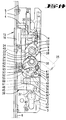
- the lock shown is as an espagnolette lock designed and has an elongated cuff 1 with attached to the lock floor 2. At a parallel distance to this is a castle ceiling 3 with unspecified Screws held. Lying on the Lock base 2 is a connecting rod connecting slide 4 led parallel to the cuff 1 and adjacent to it. The drive rod connecting slide 4 is with Driving rods 5, 6 coupled, which are flat on the Lie on the back of the cuff 1 and which are not shown, wear known locking members.
- a two-part Nut N stored in the upper area of the lock housing.
- One half of the nut 7 sits rotatable in the castle ceiling 3, while the other half of the nut 8 is rotatably received by the lock base 2, see Fig. 8.
- a change pivot lever 9 stored between the two nut halves 7, 8 is a change pivot lever 9 stored.
- the interchangeable pivot lever 9 is provided on both sides with bearing collars 11, which are in pan-shaped Recesses 12 of the side walls of the nut halves form fit. So the nut halves 7, 8 in addition to their storage in the castle floor 2 or castle ceiling 3 additional storage using the interchangeable swivel lever 9.
- the change pivot lever 9 forms a trap attack arm 13, which extends into the area of a trap tail 14 a trap 15 extends.
- a trap 15 extends in the trap tail 14
- a pin is used to fix it Cross screw 18 of the trap tail 14, which in a Ring groove of the pin 17 dips.
- This configuration allows the trap head 16 to be turned over Trap spring serving compression spring 19 acts on the Trap 14 and thus the trap 15 in the direction of advance.
- Trap spring serving compression spring 19 acts on the Trap 14 and thus the trap 15 in the direction of advance.
- One between the castle floor 2 and the castle ceiling 3 located spring housing 20 protrudes with a projection 21 in the trajectory of the trap tail 14 and thus limits the outward movement of the trap 15.
- the dovetail 14 takes the dovetail one parallel to the castle floor 2 and castle ceiling 3 relocatable driver 22. One reaches into this on the trap tail 14 set screw 23. By adjusting the same from the lock housing exterior ago it is possible that the driver 22 either with one or the other half of the nut cooperates. in the In the present case, the driver 22 extends in the Movement range of an arm 24 of the door handle 25 associated nut half 8, see Fig. 9. In this Figure is the nut half assigned to the door handle 26 7 not shown
- the nut half 7 assigned to the outside door handle 26 also has a congruent to the arm 24 Arm 27, which in the embodiment however, has no effect. Therefore it is from the Outside of door by pushing downwards not possible to withdraw the trap 15.
- Each nut half 7, 8 is approximately diametrically opposite, horizontal shoulders 28 fitted. On the two shoulders 28 each half of the nut 7, 8 each engage a spring-loaded slide 29 or 30.
- the slider 29 is the lock cover 3 turned and has an angled extension 29 ', which is acted upon by a compression spring 31 of the spring housing 20 becomes. Separately from the compression spring 31 that takes Spring housing 20 a further compression spring 32. This acts on the extension 30 'of the lock base 2 guided slide 30.
- Each half of the nut has below the polygonal opening 10 7, 8 an edge-side recess 33 into which a Radial extension 34 one stored below the nut N.
- Swivel arm 35 engages with play.
- the Swivel arm 35 is in turn in the castle floor 2 and Castle ceiling 3 rotatably mounted.
- the Radial extension 34 of the edge 33 'of the recess 33 adjacent, cf. in particular Fig. 9. be it from inside or outside therefore no take-along due to the movement play of the swivel arm 35.
- the one below the trap 15 in the castle housing Bolt 36 is a vertically rising tumbler 37 assigned.
- the latter has a locking extension 38, which in the closed bolt position in a locking recess 39 of the latch 36 dips.
- another Locking recess 40 is provided, which is in the closed position Bolt 36 with the locking extension 38 of the tumbler 37 cooperates.
- the tumbler 37 is in the reverse direction acted upon by a torsion spring 41 such that the Tumbler 37 with its lower area in a closing engagement opening 42 of the bolt tail 36 'protrudes.
- the closing engagement opening 42 serves for entry a lock bit 43 one in the lock housing used lock cylinder 44.
- the swivel arm 35 has a control cam 50 provided which one for lifting the tumbler 37 Nose 51 of a lever arm 52 is applied.
- This control cam 50 is forked through an incision 53, one cam tine 54 in the closed Position and the other cam tine 55 in the pre-closed Locking position applied to the nose 51.
- the lever arm 52 is the an arm of a substantially transverse to the drive rod displacement direction double lever mounted in the lock housing D, whose other arm 56 on the tumbler 37 attacks.
- the arm 56 has a slot 57 provided, in which a coupling pin 58 of the tumbler 37 engages.
- a lock pin 59 on the lock housing side is used.
- the bolt 36 is connected via a slot / pin control the connecting rod connecting slide 4 is motion-coupled.
- the latch 36 has an in Slit sloping towards its top 60, in which a driver pin 61 of the connecting rod connecting slide 4 dips. 7, ie in the closed position of the latch 36, is located the driver pin 61 at the lower end of the slope increasing slot 60.
- the swivel arm is in the area of its control cam 50 35 equipped with a slot 62 open at the edge, in which a pin 63 of the connecting rod connecting slide 4 engages positively.
- the outside door handle 26 becomes opposite to the normal handle operating direction pivoted in the upward direction, so the position shown in FIGS. 3 and 10.
- the edge 33 acts on it the radial extension 34 and displaces the swivel arm opposite to the nut turn.
- pivoting of the swivel arm 35 acts on its cam tines 54 the nose 51 of the lever arm 52 and pivots it counterclockwise, with the slot / pin engagement 57, 58 the tumbler 37 is raised, the locking extension 38 of the locking recess 39 of the Riegel's 36 leaves.
- the closing of the latch 36 and the relocation of the Driving rods 5, 6 in the locking position can also be made by means of the inside handle 25.
- the door handle 25 is in the upward direction 5 and 12 to pivot. It will be there taken through the door handle 25, the nut half 8, which in turn over the recess edge 33 ' the pivot arm 35 is pivoted. This acts on the nose 51 of the lever arm 52 via the cam tines 54 and pivots it while lifting it out the tumbler 37.
- the pin / slot engagement 62, 63 of the connecting rod connecting slide 4 in Moved upwards and thus over the pin / slot engagement 60, 61 the latch 36 is closed.
- the slider 30 Compression spring 32 tensioned. After releasing the inside door handle 25 brings the spring-loaded slide 30th the nut half 8 back to its neutral middle position, while the swing arm 35 in its previously occupied Position persists due to the play of movement.
- the locking and unlocking of the latch 36 is also possible by means of the lock cylinder 44, of the guard lock 43 the tumbler 37 is lifted.
- the bolt shift leads to a shift of the Espagnolette connecting slide 4 and to twist of the swivel arm 35, the radial extension 34 of which due to the play in the recess 33 moves.
Abstract
Description
Die Erfindung betrifft ein Schloß mit nußbetätigbarer Falle und schlüsselbetätigbarem Riegel, wobei der vorgeschlossene Riegel gemeinsam mit der Falle durch Nußbetätigung zurückziehbar ist und wobei die dem Riegel zugeordnete Zuhaltung von einem schwenkarmgesteuerten Hebelarm ausgehoben wird.The invention relates to a lock with nut actuated Latch and key-operated bolt, the pre-closed Bolt together with the latch by nut actuation is retractable and the associated with the bolt Guard locking from a swivel arm-controlled lever arm is excavated.
Ein Schloß der in Rede stehenden Art ist bekannt aus der DE-OS 24 33 322, wobei die Nuß einen ihr angeformten Schwenkarm ausbildet. Letzterer besitzt einen das Schloßgehäuse überragenden Mitnehmerbolzen zum Antrieb einer außenseitig auf dem Schloßgehäuse aufliegenden Treibstange. Das Schloß kann bei vorgetretener Falle und Riegel in einer Paniksituation durch Drückerbetätigung geöffnet werden. Hierbei wird beim Verschwenken der Nuß einerseits die Treibstange in ihre Entriegelungsstellung bewegt. Ferner verlagert der Schwenkarm einen Hebelarm, welcher die Zuhaltung anhebt. Sodann wird durch den Schwenkarm zeitverzögert ein weiterer Hebel verschwenkt, welcher den Riegel zurückschließt.A castle of the type in question is known from DE-OS 24 33 322, wherein the nut is molded onto it Swivel arm trained. The latter owns one Lock housing protruding drive pin for the drive one lying on the outside of the lock housing Connecting rod. The lock can be used Trap and bolt in a panic situation Lever actuation can be opened. Here, the Swiveling the nut on the one hand the drive rod in their Unlocked position moved. Furthermore, the Swivel arm a lever arm that raises the guard locking. Then the swivel arm delays the time another lever pivots, which locks the bolt concludes.
Dem Gegenstand der Erfindung liegt die Aufgabe zugrunde, ein gattungsgemäßes Schloß von einfacherem, gedrängtem und schließtechnisch günstigem Aufbau anzugeben.The object of the invention is based on the object a generic lock of simpler, more compact and to specify a structure that is favorable in terms of locking technology.
Diese Aufgabe ist zunächst und im wesentlichen bei
einem Schloß mit den Merkmalen des Anspruchs 1 gelöst,
wobei darauf abgestellt ist, daß der Schwenkarm von
einem nußgesteuerten, auf einen Treibstangen-Anschlußschieber
wirkenden Treibstangen-Antriebshebel gebildet
und der Riegel durch Treibstangen-Anschlußschieberverlagerung
schließbar ist. This task is first and foremost
a lock with the features of
Die Unteransprüche betreffen vorteilhafte Weiterbildungen der erfindungsgemäßen Lösung.The subclaims relate to advantageous further developments the solution according to the invention.
Zufolge derartiger Ausgestaltung ist ein gattungsgemäßes
Schloß von einfachem, klassischem Aufbau angegeben,
welches sich zusätzlich durch eine gedrängte
Bauform auszeichnet. Die Treibstange selbst liegt nun
nicht mehr flächig auf einer Schloßgehäuseseitenwand
auf, sondern beinhaltet einen im Schloßgehäuse geführten
Treibstangen-Anschlußschieber, von welchem die
Treibstangen so ausgehen können, daß sie flächig auf
der Rückseite der Stulpe aufliegen. Sodann ist der
Schwenkarm von dem nußgesteuerten, auf dem Treibstangen-Anschlußschieber
wirkenden Treibstangen-Antriebshebel
gebildet. Auf diese Weise erfüllt der Schwenkarm
eine Doppelfunktion: Einerseits bedingt seine Verlagerung
-von der Nuß verursacht- eine Schubbewegung
des Treibstangen-Anschlußschiebers und andererseits
verschwenkt er den Hebelarm, mittels welchem die Zuhaltung
ausgehoben wird. Erfolgt eine entsprechende Nußbetätigung,
so wird über den Schwenkarm der Treibstangen-Anschlußschieber
bewegt, welcher seinerseits den Riegel
schließt, nachdem zuvor die zuhaltung ausgehoben wird.
Die Nuß, Schwenkarm und Hebelarm lassen sich räumlich
dicht gedrängt in einer Übereinanderlage im Schloßgehäuse
unterbringen, so daß sich das Schloß mit geringem
Dornmaß erstellen läßt. Im einzelnen ist der zwischen
Nuß und Hebelarm gelagerte Schwenkarm mit einem Steuernocken
ausgestattet, welcher bei Verlagerung des
Schwenkarmes, hervorgerufen durch Nußdrehung, eine Nase
des Hebelarms beaufschlagt, diesen verschwenkt und
dabei die Zuhaltung aushebt. Hierbei wird der Schwenkarm
zur Nußdrehung gegensinnig angetrieben. Weiterhin
ist der Steuernocken durch einen Einschnitt gegabelt.
Der eine Nockenzinken beaufschlagt in der rückgeschlossenen
Stellung und der andere Nockenzinken in der vorgeschlossenen
Riegelstellung die Nase des Hebelarmes
verbunden damit, daß stets die Zuhaltung aus dem Sperreingriff
zum Riegel ausgehoben wird. Da letzterer über
die Schlitz/Zapfensteuerung mit dem Treibstangen-Anschlußschieber
gekoppelt ist, erfolgt einhergehend mit
einer Verlagerung des Treibstangen-Anschlußschiebers
das Schließen des Riegels, sei es in die Vorschlußstellung
oder in die rückgeschlossene Position. Zu diesem
Zweck befindet sich im Bereich des Steuernockens ein
randseitig offener Schlitz, in den der Zapfen des Treibstangen-Anschlußschiebers
kuppelnd eingreift. So dient
der Steuernocken nicht nur zum Ausheben des Hebelarmes,
sondern beinhaltet zusätzlich noch den Schlitz zur
formschlüssigen Mitnahme des Treibstangen-Anschlußschiebers.
Bezüglich des Hebelarmes handelt es sich um den
einen Arm eines im wesentlichen quer zur Treibstangen-Verlagerungsrichtung
im Schloßgehäuse gelagerten Doppelhebels,
dessen anderer Arm an der Zuhaltung angreift.
Auch hier kann der Angriff im Wege einer Zapfen/Schlitzsteuerung
erfolgen. Um eine Betätigung des Schlosses
unabhängig sowohl mittels eines Innendrückers als auch
mittels eines Außendrückers vornehmen zu können, ist
die Nuß zweigeteilt und/oder in einer abgefederten
Mittelstellung gehalten. Sodann besitzt die Nuß bzw.
jede Nußhälfte eine randseitige Aussparung, in welche
ein Radialfortsatz des Schwenkarmes mit Bewegungsspiel
eingreift derart, daß bei von innen oder außen erfolgender
Drückeraufwärtsbewegung der Riegel vorschließt und
bei zumindest einseitiger Drückerabwärtsbewegung der
Riegel und die Falle gleichzeitig zurückziehbar sind.
Durch von außen oder innen erfolgende Drückeraufwärtsbewegung
kann somit die Treibstange in die Verriegelungsstellung
und damit auch der Riegel in seine Vorschließstellung
gebracht werden, also ohne Schlüsselbetätigung.
Ferner lassen sich zumindest bei einseitiger
Drückerabwärtsbetätigung Riegel und Falle gleichzeitig
zurückziehen also unter Verwirklichung einer Antipanik-Funktion.
Durch den nebengeordneten Anspruch 10 wird
ebenfalls die Erfindungsaufgabe gelöst, und zwar dadurch,
daß der Wechsel-Schwenkhebel zwischen den beiden
Nußhälften gelagert ist. Ein gesonderter Bauraum für
den Wechsel-Schwenkhebel entfällt somit, so daß diese
Maßnahme ebenfalls zu dem gedrängten, einfachen Aufbau
des Schlosses beiträgt. Im übrigen stellt der Wechsel-Schwenkhebel
eine Trennwand zwischen den Mehrkantöffnungen
der beiden Nußhälften dar, so daß die sich gegenüberliegenden
Drückerdorne sich nicht gegenseitig beeinträchtigen,
bspw. dadurch, daß der eine Drückerdorn zu
weit über die ihm zugeordnete Nußhälfte hinausragt und
in die andere eintritt. Stabilisierend wirkt sich
dabei die Maßnahme aus, daß der Wechsel-Schwenkhebel
beidseitig Lagerbunde aufweist, welche in pfannenförmigen
Ausnehmungen der Nußhälften-Seitenwände einliegen.
Somit ist auch jede Nußhälfte beidseitig abgestützt.As a result of such a configuration is a generic
Lock of simple, classic construction specified,
which is additionally characterized by a crowded
Excellent design. The connecting rod itself now lies
no longer flat on a lock housing side wall
on, but includes a guided in the lock housing
Espagnolette connecting slide, of which the
Driving rods can go out so that they are flat
rest on the back of the cuff. Then there is
Swivel arm from the nut-controlled, on the connecting rod connecting slide
acting drive rod drive lever
educated. In this way, the swivel arm fulfills
a double function: on the one hand, its relocation causes
- caused by the nut - a pushing movement
of the connecting rod connecting slide and on the other hand
he pivots the lever arm, by means of which the tumbler
is excavated. If there is a corresponding nut actuation,
so the drive rod connecting slide is on the swivel arm
which in turn moves the bolt
closes after the guard locking is released beforehand.
The nut, swivel arm and lever arm can be spatially
tightly packed in a stack on top of each other in the lock housing
accommodate so that the lock with little
Backset can be created. In particular, it is between
Nut and lever arm mounted swivel arm with a control cam
equipped, which when the
Swivel arm, caused by nut rotation, a nose
acted on the lever arm, pivoted and
the guard locks out. Here the swivel arm
driven in opposite directions to the nut rotation. Farther
the control cam is forked through an incision.
One cam tine acts on the closed one
Position and the other cam tine in the pre-closed
Lock position the nose of the lever arm
connected with the fact that the guard locking interlock
to the bar is raised. Since the latter over
the slot / pin control with the connecting rod connecting slide
coupled, takes place along with
a displacement of the connecting rod connecting slide
closing the bolt, be it in the closing position
or in the closed position. To this
Purpose is in the area of the control cam
slot open on the edge, into which the pin of the connecting rod connecting slide
engages with clutch. So serves
the control cam not only for lifting the lever arm,
but also contains the slot for
positive driving of the connecting rod connecting slide.
Regarding the lever arm, it is the
an arm of a substantially transverse to the drive rod displacement direction
double lever mounted in the lock housing,
whose other arm attacks the tumbler.
Here, too, the attack can be controlled by means of a tenon / slot control
respectively. To operate the lock
independently using an inside handle as well
to be able to make using an outside handle
the nut split in two and / or in a sprung
Held in the middle position. Then the nut or
each nut half has an edge-side recess in which
a radial extension of the swivel arm with play
intervenes in such a way that when taking place from the inside or outside
Lever pushes upward and closes
with at least one-sided downward movement of the
Bolts and the latch are retractable at the same time.
By pushing the lever upwards from outside or inside
can thus the drive rod in the locking position
and with it the bolt in its closing position
brought, so without key operation.
Furthermore, at least one-sided
Lever downward actuation bolt and latch simultaneously
withdraw with the realization of an anti-panic function.
By the
Nachstehend wird ein Ausführungsbeispiel der Erfindung anhand der Zeichnungen veranschaulicht. Es zeigt
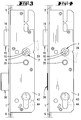
- Fig. 1
- eine Ansicht des Schlosses mit Antipanik-Funktion, von der Türaußenseite her gesehen, und zwar bei zurückgeschlossenem Riegel,
- Fig. 2
- eine klappfigürliche Darstellung der Fig. 1,
- Fig. 3
- eine der Fig. 1 entsprechende Darstellung, wobei abweichend von dieser der äußere Türdrücker in Aufwärtsrichtung verlagert ist einhergehend mit einer Verlagerung der Treibstange in die Verriegelungsstellung und einem Vorschließen des Riegels,
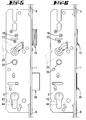
- Fig. 4
- eine Darstellung wie Fig. 3, wobei der äußere Türdrücker in Abwärtsrichtung verschwenkt ist unter Zurückziehen des Riegels, ohne jedoch die Falle mitzunehmen,
- Fig. 5
- eine Ansicht des Schlosses, von der Türinnenseite her gesehen, bei in Aufwärtsrichtung verlagertem Türinnendrücker einhergehend mit einem Vorschließen des Riegels und Verlagerung der Treibstange in ihre Verriegelungsstellung,
- Fig. 6
- eine der Fig. 5 ähnliche Darstellung, wobei der Türinnendrücker in Abwärtsrichtung betätigt ist bei gleichzeitigem Zurückziehen von Falle und Riegel sowie Entriegeln der Falle,
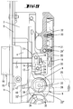
- Fig. 7
- eine Ansicht des Schlosses bei abgenommener Schloßdecke in zurückgezogener Riegelstellung, von der Türaußenseite her gesehen,
- Fig. 8
- den Schnitt nach der Linie VIII-VIII in Fig. 7,
- Fig. 9
- in vergrößerter Darstellung den oberen Bereich des Schlosses gemäß der Grundstellung, teilweise aufgebrochen,
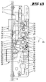
- Fig. 10
- die Darstellung wie Fig. 7, jedoch bei aufwärts verlagertem Außendrücker, vergleichbar mit der Stellung gemäß Fig. 3,
- Fig. 11
- eine Darstellung wie Fig. 10, wobei der Türaußendrücker in Abwärtsrichtung betätigt ist bei Zurückziehen des Riegels gemäß Fig. 4,
- Fig. 12
- eine Darstellung wie Fig. 7, wobei der Türinnendrücker in Aufwärtsrichtung verlagert ist unter Mitnahme der zugehörigen Nußhälfte,
- Fig. 13
- eine der Fig. 12 entsprechende Darstellung, und zwar während der Abwärtsverlagerung des Türinnendrückers einhergehend mit einer Mitnahme der zugehörigen Nußhälfte unter Verschwenken des Schwenkarmes und Ausheben der Zuhaltung über den Hebelarm,
- Fig. 14
- die Folgedarstellung der Fig. 13, und zwar bei vollständig zurückgezogenem Riegel und in die Entriegelungsstellung gebrachten Treibstangen,
- Fig. 15
- perspektivische Darstellungen des Schwenkarmes,
- Fig. 16
- perspektivische Darstellungen des Riegels,
- Fig. 17
- eine perspektivische Darstellung der Nußhälften mit dazwischen angeordnetem Wechsel-Schwenkhebel und
- Fig. 18
- eine andere perspektivische Darstellung der Nußhälften mit dazwischen befindlichem Wechsel-Schwenkhebel.
- Fig. 1
- a view of the lock with anti-panic function, seen from the outside of the door, with the bolt locked,
- Fig. 2
- 2 shows a foldable illustration of FIG. 1,
- Fig. 3
- 1 shows a representation corresponding to FIG. 1, with the outer door handle being shifted upwards in this way, accompanied by a displacement of the drive rod into the locking position and a pre-closing of the bolt,
- Fig. 4
- a representation like Fig. 3, wherein the outer lever handle is pivoted in the downward direction while withdrawing the bolt, but without taking the latch,
- Fig. 5
- 1 shows a view of the lock, seen from the inside of the door, with the door handle being displaced in the upward direction, accompanied by the latch locking and the displacement of the drive rod into its locking position,
- Fig. 6
- 5 shows a representation similar to FIG. 5, the inside door handle being actuated in the downward direction while the latch and bolt being pulled back and the latch being unlocked,
- Fig. 7
- a view of the lock with the lock cover removed in the retracted bolt position, seen from the outside of the door,
- Fig. 8
- the section along the line VIII-VIII in Fig. 7,
- Fig. 9
- in an enlarged view the upper area of the lock according to the basic position, partially broken open,
- Fig. 10
- the representation as in FIG. 7, but with the outer handle shifted upwards, comparable to the position in accordance with FIG. 3,
- Fig. 11
- 10 is an illustration like FIG. 10, with the outside door handle being actuated in the downward direction when the bolt is withdrawn according to FIG. 4,
- Fig. 12
- a representation like Fig. 7, wherein the door handle is shifted in the upward direction with the entrainment of the associated nut half,
- Fig. 13
- 12 shows a representation corresponding to FIG. 12, namely during the downward displacement of the inside door handle, along with entrainment of the associated nut half while pivoting the swivel arm and lifting the tumbler via the lever arm,
- Fig. 14
- 13, namely with the bolt fully retracted and the drive rods brought into the unlocking position,
- Fig. 15
- perspective representations of the swivel arm,
- Fig. 16
- perspective representations of the bolt,
- Fig. 17
- a perspective view of the nut halves with interchangeable swivel lever and
- Fig. 18
- another perspective view of the nut halves with interchangeable swivel lever.
Das dargestellte Schloß ist als Treibstangenschloß
gestaltet und besitzt eine langgestreckte Stulpe 1 mit
daran angesetztem Schloßboden 2. In parallelem Abstand
zu diesem ist eine Schloßdecke 3 mit nicht näher bezeichneten
Schrauben gehaltert. Aufliegend auf dem
Schloßboden 2 ist ein Treibstangen-Anschlußschieber 4
parallel zur Stulpe 1 und benachbart zu dieser geführt.
Der Treibstangen-Anschlußschieber 4 ist mit
Treibstangen 5, 6 gekuppelt, welche flächig auf der
Rückseite der Stulpe 1 aufliegen und welche nicht dargestellte,
an sich bekannte Verriegelungsglieder tragen.The lock shown is as an espagnolette lock
designed and has an elongated
Im oberen Bereich des Schloßgehäuses ist eine zweigeteilte
Nuß N gelagert. Die eine Nußhälfte 7 sitzt
drehbar in der Schloßdecke 3, während die andere Nußhälfte
8 drehbar vom Schloßboden 2 aufgenommen ist,
vergl. Fig. 8. Zwischen den beiden Nußhälften 7, 8 ist
ein Wechsel-Schwenkhebel 9 gelagert. Dieser bildet
eine Trennwand zwischen den Mehrkantöffnungen 10 der
beiden Nußhälften 7, 8. Der Wechsel-Schwenkhebel 9 ist
beidseitig mit Lagerbunden 11 versehen, welche in pfannenförmigen
Ausnehmungen 12 der Nußhälften-Seitenwände
formschlüssig einliegen. So erhalten die Nußhälften 7,
8 neben ihrer Lagerung in Schloßboden 2 bzw. Schloßdecke
3 eine zusätzliche Lagerung durch den Wechsel-Schwenkhebel
9.In the upper area of the lock housing is a two-part
Nut N stored. One half of the
Der Wechsel-Schwenkhebel 9 bildet einen Fallenangriffsarm
13 aus, welcher sich bis in den Bereich eines Fallenschwanzes
14 einer Falle 15 erstreckt. In dem Fallenschwanz
14 sitzt drehbar ein vom Fallenkopf 16 ausgehender
Zapfen 17. Zu dessen Festlegung dient eine
Querschraube 18 des Fallenschwanzes 14, welche in eine
Ringnut des Zapfens 17 eintaucht. Diese Ausgestaltung
gestattet ein Umwenden des Fallenkopfes 16. Eine als
Fallenfeder dienende Druckfeder 19 beaufschlagt den
Fallenschanz 14 und damit die Falle 15 in Vortrittsrichtung.
Ein zwischen Schloßboden 2 und Schloßdecke 3
befindliches Federgehäuse 20 ragt mit einem Vorsprung
21 in die Bewegungsbahn des Fallenschwanzes 14 und
begrenzt damit die Auswärtsbewegung der Falle 15.The
Schwalbenschwanzgeführt nimmt der Fallenschwanz 14
einen parallel zum Schloßboden 2 und Schloßdecke 3
verlagerbaren Mitnehmer 22 auf. In diesen greift eine
am Fallenschwanz 14 gehalterte Stellschraube 23 ein.
Durch Verstellung derselben vom Schloßgehäuseäußeren
her ist es möglich, daß der Mitnehmer 22 entweder mit
der einen oder anderen Nußhälfte zusammenwirkt. Im
vorliegenden Fall erstreckt sich der Mitnehmer 22 im
Bewegungsbereich eines Armes 24 der dem Türinnendrücker
25 zugeordneten Nußhälfte 8, vergl. Fig. 9. In dieser
Figur ist die dem Türaußendrücker 26 zugeordnete Nußhälfte
7 nicht dargestelltThe
Die dem Türaußendrücker 26 zugeordnete Nußhälfte 7
besitzt ebenfalls einen deckungsgleich zum Arm 24 verlaufenden
Arm 27, welcher beim Ausführungsbeispiel
jedoch nicht zur Wirkung gelangt. Daher ist es von der
Türaußenseite durch abwärts gerichtete Drückerbetätigung
nicht möglich, die Falle 15 zurückzuziehen.The
Jede Nußhälfte 7, 8 ist mit sich etwa diametral gegenüberliegenden,
horizontal verlaufenden Schultern 28
ausgestattet. An den beiden Schultern 28 jeder Nußhälfte
7, 8 greift je ein federbeaufschlagter Schieber 29
bzw. 30 an. Der Schieber 29 ist der Schloßdecke 3
zugekehrt und besitzt einen abgewinkelten Fortsatz 29',
der von einer Druckfeder 31 des Federgehäuses 20 beaufschlagt
wird. Getrennt von der Druckfeder 31 nimmt das
Federgehäuse 20 eine weitere Druckfeder 32 auf. Diese
beaufschlagt den Fortsatz 30' des auf dem Schloßboden 2
geführten Schiebers 30. Durch diese federbelasteten
Schieber 29, 30 werden die Nußhälften 7, 8 in einer
Mittelstellung gehalten, in welcher die Türdrücker 25,
26 etwa horizontal ausgerichtet sind.Each
Unterhalb der Mehrkantöffnung 10 besitzt jede Nußhälfte
7, 8 eine randseitige Aussparung 33, in welche ein
Radialfortsatz 34 eines unterhalb der Nuß N gelagerten
Schwenkarmes 35 mit Bewegungsspiel eingreift. Der
Schwenkarm 35 ist seinerseits in Schloßboden 2 und
Schloßdecke 3 drehbar gelagert. In der Grundstellung
7, also bei zurückgeschlossenem Riegel 36, ist der
Radialfortsatz 34 der Randkante 33' der Aussparung 33
benachbart, vergl. insbesondere Fig. 9. Bei Drückerabwärtsbetätigung,
sei es von innen oder von außen, erfolgt
also aufgrund des Bewegungsspiels keine Mitnahme
des Schwenkarmes 35.Each half of the nut has below the
Dem unterhalb der Falle 15 im Schlofgehäuse geführten
Riegel 36 ist eine senkrecht steigende Zuhaltung 37
zugeordnet. Letztere besitzt einen Sperrfortsatz 38,
welcher in der zurückgeschlossenen Riegelstellung in
eine Sperrausnehmung 39 des Riegels 36 eintaucht. Im
Anschluß an die Sperrausnehmung 39 ist eine weitere
Sperrausnehmung 40 vorgesehen, die bei vorgeschlossenem
Riegel 36 mit dem Sperrfortsatz 38 der Zuhaltung 37
zusammenwirkt. Die Zuhaltung 37 wird in Sperrichtung
von einer Drehfeder 41 beaufschlagt derart, daß die
Zuhaltung 37 mit ihrem unteren Bereich in eine Schließeingriffsöffnung
42 des Riegelschwanzes 36' hineinragt.
Die Schließeingriffsöffnung 42 dient zum Eintritt
eines Schließbartes 43 eines in das Schloßgehäuse
eingesetzten Schließzylinders 44. Bei zurückgeschlossenem
Riegel 36 ragt in den Bewegungsbereich des Schließbartes
43 das untere, abgewinkelte Ende 45' einer Übertragungsstange
45. Letztere ist an ihrem oberen Ende
mit einer Bohrung 46 versehen, in welche ein Kupplungsvorsprung
47 des Wechsel-Schwenkhebels 9 eingreift.
Sodann besitzt die Übertragungsstange 45 einen Steuerfinger
48 zum Zusammenwirken mit einer Steuernische 49
des Riegels 36. Bei zurückgeschlossenem Riegel 36
befindet sich der Steuerfinger 48 in dem linksseitigen
Endbereich der Steuernische 49 und ist somit in seiner
Position gemäß Fig. 7 fixiert.The one below the
Der Schwenkarm 35 ist mit einem Steuernocken 50
versehen, welcher zum Ausheben der Zuhaltung 37 eine
Nase 51 eines Hebelarmes 52 beaufschlagt. Dieser Steuernocken
50 ist durch einen Einschnitt 53 gegabelt,
wobei der eine Nockenzinken 54 in der rückgeschlossenen
Stellung und der andere Nockenzinken 55 in der vorgeschlossenen
Riegelstellung die Nase 51 beaufschlagt.
Bezüglich des Hebelarmes 52 handelt es sich um den
einen Arm eines im wesentlichen quer zur Treibstangenverlagerungsrichtung
im Schloßgehäuse gelagerten Doppelhebels
D, dessen anderer Arm 56 an der Zuhaltung 37
angreift. Hierzu ist der Arm 56 mit einem Schlitz 57
versehen, in welchen ein Kupplungszapfen 58 der Zuhaltung
37 eingreift. Zur Lagerung des Doppelhebels D
dient übrigens ein schloßgehäuseseitiger Stehzapfen 59.The
Der Riegel 36 ist über eine Schlitz/Zapfensteuerung mit
dem Treibstangen-Anschlußschieber 4 bewegungsgekoppelt.
Zu diesem Zweck besitzt der Riegel 36 einen in
Richtung seiner Oberseite schräg ansteigenden Schlitz
60, in den ein Mitnehmerzapfen 61 des Treibstangen-Anschlußschiebers
4 eintaucht. Gemäß Fig. 7, also in der
zurückgeschlossenen Stellung des Riegels 36, befindet
sich der Mitnehmerzapfen 61 am unteren Ende des schräg
ansteigenden Schlitzes 60. The
Im Bereich seines Steuernockens 50 ist der Schwenkarm
35 mit einem randseitig offenen Schlitz 62 ausgestattet,
in welchen ein Zapfen 63 des Treibstangen-Anschlußschiebers
4 formschlüssig eingreift.The swivel arm is in the area of its
Es stellt sich folgende Wirkungsweise ein:The following mode of action occurs:
Wird der Türaußendrücker 26 entgegen der normalen Drückerbetätigungsrichtung
in Aufwärtsrichtung verschwenkt,
so stellt sich die Stellung gemäß Fig. 3 und 10 ein.
Mit dem Verschwenken des Türaußendrückers 26 wird die
diesem zugeordnete Nußhälfte 7 entgegen Uhrzeigerrichtung
verschwenkt. Die Randkante 33' beaufschlagt dabei
den Radialfortsatz 34 und verlagert den Schwenkarm
gegensinnig zur Nußdrehung. Während des Verschwenkens
des Schwenkarmes 35 beaufschlagt dessen Nockenzinken 54
die Nase 51 des Hebelarmes 52 und verschwenkt diesen
entgegen Uhrzeigerrichtung, wobei über den Schlitz/Zapfeneingriff
57, 58 die Zuhaltung 37 angehoben wird,
wobei deren Sperrfortsatz 38 die Sperrausnehmung 39 des
Riegels 36 verläßt. Einhergehend mit der Verlagerung
des Schwenkarmes 35 in Uhrzeigerrichtung wird über den
Zapfen/Schlitzeingriff 62, 63 der Treibstangen-Anschlußschieber
4 mit den daran sitzenden Treibstangen 5, 6 in
Aufwärtsrichtung verlagert. Diese Verlagerung macht
ebenfalls der Mitnehmerzapfen 61 mit, der über den
Schrägschlitz 60 eine Vorschließbewegung des Riegels 36
erzwingt, so daß danach sowohl der Riegel 36 vorgeschlossen
ist als auch die Treibstangen 5, 6 ihre Verriegelungsstellung
einnehmen. In der vorgeschlossenen
Riegelstellung hat der Sperrfortsatz 38 seine Blockierungsstellung
zum Riegel 36 eingenommen dadurch, daß er
nun in der Sperrausnehmung 40 einliegt, vergl.
Fig. 10. Durch Loslassen des Türaußendrückers 26
bringt die zuvor gespannte Druckfeder 31 den Schieber
29 in seine Ausgangsstellung zurück und damit die Nußhälfte
7 in die neutrale Mittelstellung.The
Wird aus der vorgeschlossenen Stellung des Riegels 36
der Türaußendrücker 26 in die Position gemäß Fig. 4 und
11 in Abwärtsrichtung verschwenkt, so wird über die
dabei mitgenommene, dem Türaußendrücker 26 zugeordnete
Nußhälfte 7 von deren Aussparungs-Randkante 33'' der
Radialfortsatz 34 des Schwenkarmes 35 beaufschlagt.
Bei diesem Vorgang verschwenkt der Schwenkarm 35 ebenfalls
gegensinnig zur Nußdrehung, also entgegen Uhrzeigerrichtung.
Der Nockenzinken 55 beaufschlagt die Nase
51 des Hebelarms 52 und hebt über diesen die Zuhaltung
37 aus. Somit ist der Riegel 36 nicht mehr gesperrt.
Ferner wird über den Zapfen/Schlitzeingriff 62, 63 der
Treibstangen-Anschlußschieber 4 in Abwärtsrichtung
verlagert, wobei der Mitnehmerzapfen 61 über den Schrägschlitz
60 des Riegels 36 eine Einwärtsverlagerung
desselben in die zurückgeschlossene Stellung erzwingt,
vergl. Fig. 11. Bei diesem Vorgang bleibt die Falle 15
in ihrer Vortrittsstellung stehen, da sie von der Nußhälfte
7 nicht mitgenommen werden kann. Das Zurückziehen
der Falle 15 bzw. das Öffnen der mit dem erfindungsgemäßen
Schloß bestückten Tür ist somit von außen nur
durch Wechselbetätigung möglich. Dies verlangt den zum
Schließzylinder 44 zugehörigen Schlüssel. Bei Schließdrehung
in Uhrzeigerrichtung beaufschlagt der Schließbart
43 die Übertragungsstange 45 und hebt diese in
Aufwärtsrichtung an verbunden mit einem Verschwenken
des Wechsel-Schwenkhebels 9, welcher über den Fallenangriffsarm
13 den Fallenschwanz 14 beaufschlagt und
somit die Falle 15 in Einwärtsrichtung zieht.Is from the pre-closed position of
Bei Fortlassen der Randkante 33'' an der Nußhälfte 7
wäre bei dieser Außendrückerbetätigung der Riegel 36
nicht zurückschließbar. Dann müßte das Zurückschließen
ausschließlich durch den Schließzylinder 44 erfolgen.If the
Das Vorschließen des Riegels 36 und die Verlagerung der
Treibstangen 5, 6 in die Verriegelungsstellung kann
auch mittels des Innendrückers 25 vorgenommen werden.
Hierzu ist der Türinnendrücker 25 in Aufwärtsrichtung
gemäß Fig. 5 und 12 zu verschwenken. Es wird dabei
durch den Türinnendrücker 25 die Nußhälfte 8 mitgenommen,
die ihrerseits über die Aussparungs-Randkante 33'
den Schwenkarm 35 verschwenkt. Dieser beaufschlagt
über den Nockenzinken 54 die Nase 51 des Hebelarmes 52
und verschwenkt diesen unter gleichzeitigem Ausheben
der Zuhaltung 37. Ferner wird über den Zapfen/Schlitzeingriff
62, 63 der Treibstangen-Anschlußschieber 4 in
Aufwärtsrichtung bewegt und damit über den Zapfen/Schlitzeingriff
60, 61 der Riegel 36 vorgeschlossen.
Bei diesem Vorgang wird über den Schieber 30 die
Druckfeder 32 gespannt. Nach Loslassen des Türinnendrückers
25 bringt der federbeaufschlagte Schieber 30
die Nußhälfte 8 in ihre neutrale Mittelstellung zurück,
während der Schwenkarm 35 in seiner zuvor eingenommenen
Stellung aufgrund des Bewegungsspiels verharrt.The closing of the
In einer Paniksituation ist es nun von der Türinnenseite
her durch Beaufschlagung des Türinnendrückers 25 in
Abwärtsrichtung möglich, sowohl die Falle 15 als auch
den Riegel 36 zurückzuziehen als auch die Treibstangen
5, 6 in ihre Entriegelungsstellung zu bringen. In der
Anfangsphase der Türinnendrücker-Betätigung, vergl.
Fig. 13, beaufschlagt der Nockenzinken 55 die Nase 51
des Hebelarms 52, woraufhin dieser verschwenkt und die
Zuhaltung 37 aushebt. Bei weiterer Beaufschlagung des
Radialfortsatzes 34 durch die Aussparungs-Randkante
33'' der Nußhälfte 8 erfolgt eine weitere gegensinnige
Verlagerung des Schwenkarmes 35 zur Nußdrehung verbunden
mit einer Abwärtsverlagerung des Treibstangen-Anschlußschiebers
4, welcher seinerseits über die Zapfen/Schlitzverbindung
62, 63 den Riegel 36 zurücksteuert.
Es wird danach die Position gemäß Fig. 14 erreicht.
Wird nun der Türinnendrücker 25 losgelassen,
bringt der Schieber 30 die Nußhälfte 8 in ihre neutrale
Mittelstellung zurück.In a panic situation, it is now from the inside of the door
forth by acting on the
Das Zurückziehen der Falle 15 bei zurückgeschlossenem
Riegel 36 ist von der Türinnenseite her jederzeit mittels
des Türinnendrückers 25 möglich. Dabei wird von
dem Arm 24 der Nußhälfte 8 der Mitnehmer 22 des Fallenschwanzes
14 beaufschlagt und damit die Falle 15 zurückgezogen.
Auch bei diesem Vorgang wird die Druckfeder
32 über den Schieber 30 gespannt. Nach Loslassen des
Türinnendrückers 25 bringt die Fallenfeder 19 die Falle
15 in die Vortrittsstellung zurück. Ferner wird über
die Druckfeder 32 und den Schieber 30 die Nußhälfte 8
in ihre neutrale Mittelstellung zurückgesteuert.Withdrawal of the
Das Vorschließen und Zurückschließen des Riegels 36 ist
auch mittels des Schließzylinders 44 möglich, wobei von
dem Schließbart 43 die Zuhaltung 37 ausgehoben wird.
Die Riegelverlagerung führt zu einer Verlagerung des
Treibstangen-Anschlußschiebers 4 und zu einem Verdrehen
des Schwenkarmes 35, dessen Radialfortsatz 34 sich
aufgrund des Bewegungsspiels in der Aussparung 33 bewegt.The locking and unlocking of the
Alle offenbarten Merkmale sind erfindungswesentlich. In die Offenbarung der Anmeldung wird hiermit auch der Offenbarungsinhalt der zugehörigen/beigefügten Prioritätsunterlagen (Abschrift der Voranmeldung) vollinhaltlich mit einbezogen, auch zu dem Zweck, Merkmale dieser Unterlagen in Ansprüche vorliegender Anmeldung mit aufzunehmen.All the features disclosed are essential to the invention. The disclosure of the application is hereby also Disclosure content of the associated / attached priority documents (Copy of the pre-registration) in full included, also for the purpose, characteristics of this Documents in claims of the present registration with to record.
Claims (12)
Applications Claiming Priority (2)
| Application Number | Priority Date | Filing Date | Title |
|---|---|---|---|
| DE19651609 | 1996-12-12 | ||
| DE19651609A DE19651609B4 (en) | 1996-12-12 | 1996-12-12 | Lock with latch and latch |
Publications (3)
| Publication Number | Publication Date |
|---|---|
| EP0848124A2 true EP0848124A2 (en) | 1998-06-17 |
| EP0848124A3 EP0848124A3 (en) | 2000-08-09 |
| EP0848124B1 EP0848124B1 (en) | 2002-03-20 |
Family
ID=7814426
Family Applications (1)
| Application Number | Title | Priority Date | Filing Date |
|---|---|---|---|
| EP97118684A Expired - Lifetime EP0848124B1 (en) | 1996-12-12 | 1997-10-28 | Lock with latch and dead bolt |
Country Status (5)
| Country | Link |
|---|---|
| EP (1) | EP0848124B1 (en) |
| AT (1) | ATE214768T1 (en) |
| DE (2) | DE19651609B4 (en) |
| DK (1) | DK0848124T3 (en) |
| ES (1) | ES2171809T3 (en) |
Cited By (9)
| Publication number | Priority date | Publication date | Assignee | Title |
|---|---|---|---|---|
| EP0987391A2 (en) * | 1998-09-16 | 2000-03-22 | Carl Fuhr GmbH & Co. | Espagnolette lock with latch bolt having a convertible actuation mode |
| EP1020594A3 (en) * | 1999-01-18 | 2001-03-28 | Karl Fliether GmbH & Co. | Espagnolette lock |
| EP1106757A2 (en) * | 1999-12-09 | 2001-06-13 | Avocet Hardware PLC | Manually operated locking mechanism |
| EP1260660A2 (en) * | 2001-05-23 | 2002-11-27 | Talleres De Escoriaza, S.A. | Actuation device for a lock bolt |
| EP1574644A3 (en) * | 2004-03-12 | 2009-01-21 | Carl Fuhr GmbH & Co. KG | Locking system for doors, windows or similar, in particular espagnolette lock with anti-panic function and multiple lock points |
| EP2322744A1 (en) * | 2009-11-17 | 2011-05-18 | Glutz AG | Lock, rotatable clasp lock and locking system, in particular for multi-point locking for a door or window |
| WO2014118015A1 (en) * | 2013-01-30 | 2014-08-07 | Kfv Karl Fliether Gmbh & Co. Kg | Panic lock |
| WO2014118017A1 (en) * | 2013-01-30 | 2014-08-07 | Kfv Karl Fliether Gmbh & Co. Kg | Panic lock |
| CN112242659A (en) * | 2020-10-29 | 2021-01-19 | 国网山东省电力公司威海供电公司 | 10kV metal enclosed type cubical switchboard isolation barrier blocking device |
Families Citing this family (1)
| Publication number | Priority date | Publication date | Assignee | Title |
|---|---|---|---|---|
| DE102009029068A1 (en) | 2009-09-01 | 2011-03-03 | Aug. Winkhaus Gmbh & Co. Kg | lock |
Citations (3)
| Publication number | Priority date | Publication date | Assignee | Title |
|---|---|---|---|---|
| DE2433322A1 (en) * | 1974-07-11 | 1976-01-22 | Eaton Gmbh | Multiple tumbler emergency lock - has coupling device for outside and inside handle which are normally not coupled |
| EP0668425A1 (en) * | 1994-02-21 | 1995-08-23 | Hellmüller + Zingg AG | Door lock |
| US5495731A (en) * | 1993-03-26 | 1996-03-05 | Roto Frank Eisenwarenfabrik Aktiengesellschaft | Multiple-bolt door lock |
Family Cites Families (1)
| Publication number | Priority date | Publication date | Assignee | Title |
|---|---|---|---|---|
| EP0425431B1 (en) * | 1989-09-28 | 1994-10-19 | Schloss- und Beschlägefabrik AG | Lock |
-
1996
- 1996-12-12 DE DE19651609A patent/DE19651609B4/en not_active Expired - Fee Related
-
1997
- 1997-10-28 ES ES97118684T patent/ES2171809T3/en not_active Expired - Lifetime
- 1997-10-28 DK DK97118684T patent/DK0848124T3/en active
- 1997-10-28 AT AT97118684T patent/ATE214768T1/en not_active IP Right Cessation
- 1997-10-28 EP EP97118684A patent/EP0848124B1/en not_active Expired - Lifetime
- 1997-10-28 DE DE59706669T patent/DE59706669D1/en not_active Expired - Lifetime
Patent Citations (3)
| Publication number | Priority date | Publication date | Assignee | Title |
|---|---|---|---|---|
| DE2433322A1 (en) * | 1974-07-11 | 1976-01-22 | Eaton Gmbh | Multiple tumbler emergency lock - has coupling device for outside and inside handle which are normally not coupled |
| US5495731A (en) * | 1993-03-26 | 1996-03-05 | Roto Frank Eisenwarenfabrik Aktiengesellschaft | Multiple-bolt door lock |
| EP0668425A1 (en) * | 1994-02-21 | 1995-08-23 | Hellmüller + Zingg AG | Door lock |
Cited By (16)
| Publication number | Priority date | Publication date | Assignee | Title |
|---|---|---|---|---|
| EP0987391A2 (en) * | 1998-09-16 | 2000-03-22 | Carl Fuhr GmbH & Co. | Espagnolette lock with latch bolt having a convertible actuation mode |
| EP0987391A3 (en) * | 1998-09-16 | 2003-02-05 | Carl Fuhr GmbH & Co. | Espagnolette lock with latch bolt having a convertible actuation mode |
| EP1020594A3 (en) * | 1999-01-18 | 2001-03-28 | Karl Fliether GmbH & Co. | Espagnolette lock |
| EP1106757A2 (en) * | 1999-12-09 | 2001-06-13 | Avocet Hardware PLC | Manually operated locking mechanism |
| EP1106757A3 (en) * | 1999-12-09 | 2003-01-02 | Avocet Hardware PLC | Manually operated locking mechanism |
| EP1260660A2 (en) * | 2001-05-23 | 2002-11-27 | Talleres De Escoriaza, S.A. | Actuation device for a lock bolt |
| EP1260660A3 (en) * | 2001-05-23 | 2004-06-16 | Talleres De Escoriaza, S.A. | Actuation device for a lock bolt |
| EP1574644A3 (en) * | 2004-03-12 | 2009-01-21 | Carl Fuhr GmbH & Co. KG | Locking system for doors, windows or similar, in particular espagnolette lock with anti-panic function and multiple lock points |
| EP2322744A1 (en) * | 2009-11-17 | 2011-05-18 | Glutz AG | Lock, rotatable clasp lock and locking system, in particular for multi-point locking for a door or window |
| WO2014118015A1 (en) * | 2013-01-30 | 2014-08-07 | Kfv Karl Fliether Gmbh & Co. Kg | Panic lock |
| WO2014118017A1 (en) * | 2013-01-30 | 2014-08-07 | Kfv Karl Fliether Gmbh & Co. Kg | Panic lock |
| CN104956018A (en) * | 2013-01-30 | 2015-09-30 | Kfv卡尔弗利特有限责任两合公司 | Panic lock |
| CN104956018B (en) * | 2013-01-30 | 2017-08-01 | Kfv卡尔弗利特有限责任两合公司 | Urgent lock |
| RU2644111C2 (en) * | 2013-01-30 | 2018-02-07 | КФВ Карл Флиетхер ГмбХ & Ко. КГ | "anti-panic" lock |
| CN112242659A (en) * | 2020-10-29 | 2021-01-19 | 国网山东省电力公司威海供电公司 | 10kV metal enclosed type cubical switchboard isolation barrier blocking device |
| CN112242659B (en) * | 2020-10-29 | 2022-07-01 | 国网山东省电力公司威海供电公司 | 10kV metal enclosed type cubical switchboard isolation barrier blocking device |
Also Published As
| Publication number | Publication date |
|---|---|
| ES2171809T3 (en) | 2002-09-16 |
| ATE214768T1 (en) | 2002-04-15 |
| DE59706669D1 (en) | 2002-04-25 |
| DK0848124T3 (en) | 2002-07-15 |
| EP0848124A3 (en) | 2000-08-09 |
| DE19651609B4 (en) | 2007-06-21 |
| EP0848124B1 (en) | 2002-03-20 |
| DE19651609A1 (en) | 1998-06-18 |
Similar Documents
| Publication | Publication Date | Title |
|---|---|---|
| DE3844849C2 (en) | Espagnolette lock | |
| EP0796968B1 (en) | Closure device | |
| DE3447748C2 (en) | ||
| EP1932989B1 (en) | Locking device for doors, windows or similar, in particular an espagnolette lock with panic function and multi-point locking | |
| DE2914372C2 (en) | Latch bolt panic lock that can be unlocked from the outside | |
| WO2014118015A1 (en) | Panic lock | |
| EP1574644A2 (en) | Locking system for doors, windows or similar, in particular espagnolette lock with anti-panic function and multiple lock points | |
| DE3505379C2 (en) | Espagnolette lock | |
| EP0792987A2 (en) | Espagnolette locking device | |
| EP0848124B1 (en) | Lock with latch and dead bolt | |
| EP0954667B1 (en) | Lock with catch bolt for door or window | |
| DE102004003168B4 (en) | Dead bolt lock for double-leaf doors with panic function | |
| DE3631118C2 (en) | Safety lock | |
| DE3425565A1 (en) | DRIVE ROD LOCK | |
| DE102005039287A1 (en) | Anti panic lock for building door, has bar pre locked by lock beard of cylinder lock, and slide that is protuberant into rotational path of lock beard by spring load for spacing lock beard from entry area of door opening | |
| EP1020597A1 (en) | Espagnolette lock with a main lock and an auxiliary lock | |
| EP0670403B1 (en) | Doorlock, especially mortise lock | |
| DE4114007C2 (en) | Espagnolette lock | |
| DE2827939A1 (en) | Mortice lock with double mechanism - uses standard parts for left or right hand fitting to door | |
| DE3831529C2 (en) | Espagnolette lock | |
| DE2738746B2 (en) | Release device for a panic door lock with latch and bolt | |
| EP1156180B1 (en) | Lock with increased bolt shot and with an anti-panic function | |
| DE10058945A1 (en) | Sliding sash lock | |
| EP0974721B1 (en) | Lock with several bolts | |
| DE2605763C3 (en) | Espagnolette lock with latch |
Legal Events
| Date | Code | Title | Description |
|---|---|---|---|
| PUAI | Public reference made under article 153(3) epc to a published international application that has entered the european phase |
Free format text: ORIGINAL CODE: 0009012 |
|
| AK | Designated contracting states |
Kind code of ref document: A2 Designated state(s): AT BE CH DE DK ES FR GB IE IT LI LU NL |
|
| AX | Request for extension of the european patent |
Free format text: AL;LT;LV;RO;SI |
|
| PUAL | Search report despatched |
Free format text: ORIGINAL CODE: 0009013 |
|
| AK | Designated contracting states |
Kind code of ref document: A3 Designated state(s): AT BE CH DE DK ES FI FR GB GR IE IT LI LU MC NL PT SE |
|
| AX | Request for extension of the european patent |
Free format text: AL;LT;LV;RO;SI |
|
| 17P | Request for examination filed |
Effective date: 20001114 |
|
| AKX | Designation fees paid |
Free format text: AT BE CH DE DK ES FR GB IE IT LI LU NL |
|
| 17Q | First examination report despatched |
Effective date: 20010326 |
|
| GRAG | Despatch of communication of intention to grant |
Free format text: ORIGINAL CODE: EPIDOS AGRA |
|
| GRAG | Despatch of communication of intention to grant |
Free format text: ORIGINAL CODE: EPIDOS AGRA |
|
| GRAH | Despatch of communication of intention to grant a patent |
Free format text: ORIGINAL CODE: EPIDOS IGRA |
|
| GRAH | Despatch of communication of intention to grant a patent |
Free format text: ORIGINAL CODE: EPIDOS IGRA |
|
| REG | Reference to a national code |
Ref country code: GB Ref legal event code: IF02 |
|
| GRAA | (expected) grant |
Free format text: ORIGINAL CODE: 0009210 |
|
| AK | Designated contracting states |
Kind code of ref document: B1 Designated state(s): AT BE CH DE DK ES FR GB IE IT LI LU NL |
|
| REF | Corresponds to: |
Ref document number: 214768 Country of ref document: AT Date of ref document: 20020415 Kind code of ref document: T |
|
| REG | Reference to a national code |
Ref country code: CH Ref legal event code: EP |
|
| REF | Corresponds to: |
Ref document number: 59706669 Country of ref document: DE Date of ref document: 20020425 |
|
| REG | Reference to a national code |
Ref country code: CH Ref legal event code: NV Representative=s name: R. A. EGLI & CO. PATENTANWAELTE |
|
| REG | Reference to a national code |
Ref country code: DK Ref legal event code: T3 |
|
| GBT | Gb: translation of ep patent filed (gb section 77(6)(a)/1977) |
Effective date: 20020624 |
|
| ET | Fr: translation filed | ||
| REG | Reference to a national code |
Ref country code: ES Ref legal event code: FG2A Ref document number: 2171809 Country of ref document: ES Kind code of ref document: T3 |
|
| PLBE | No opposition filed within time limit |
Free format text: ORIGINAL CODE: 0009261 |
|
| STAA | Information on the status of an ep patent application or granted ep patent |
Free format text: STATUS: NO OPPOSITION FILED WITHIN TIME LIMIT |
|
| 26N | No opposition filed |
Effective date: 20021223 |
|
| PGFP | Annual fee paid to national office [announced via postgrant information from national office to epo] |
Ref country code: IE Payment date: 20051005 Year of fee payment: 9 Ref country code: FR Payment date: 20051005 Year of fee payment: 9 |
|
| PGFP | Annual fee paid to national office [announced via postgrant information from national office to epo] |
Ref country code: LU Payment date: 20051010 Year of fee payment: 9 Ref country code: DK Payment date: 20051010 Year of fee payment: 9 Ref country code: CH Payment date: 20051010 Year of fee payment: 9 |
|
| PGFP | Annual fee paid to national office [announced via postgrant information from national office to epo] |
Ref country code: BE Payment date: 20051013 Year of fee payment: 9 |
|
| PGFP | Annual fee paid to national office [announced via postgrant information from national office to epo] |
Ref country code: ES Payment date: 20051014 Year of fee payment: 9 |
|
| PG25 | Lapsed in a contracting state [announced via postgrant information from national office to epo] |
Ref country code: IE Free format text: LAPSE BECAUSE OF NON-PAYMENT OF DUE FEES Effective date: 20061030 |
|
| PG25 | Lapsed in a contracting state [announced via postgrant information from national office to epo] |
Ref country code: LI Free format text: LAPSE BECAUSE OF NON-PAYMENT OF DUE FEES Effective date: 20061031 Ref country code: DK Free format text: LAPSE BECAUSE OF NON-PAYMENT OF DUE FEES Effective date: 20061031 Ref country code: CH Free format text: LAPSE BECAUSE OF NON-PAYMENT OF DUE FEES Effective date: 20061031 |
|
| REG | Reference to a national code |
Ref country code: CH Ref legal event code: PL |
|
| REG | Reference to a national code |
Ref country code: IE Ref legal event code: MM4A |
|
| REG | Reference to a national code |
Ref country code: FR Ref legal event code: ST Effective date: 20070629 |
|
| BERE | Be: lapsed |
Owner name: KARL *FLIETHER G.M.B.H. & CO. Effective date: 20061031 |
|
| REG | Reference to a national code |
Ref country code: ES Ref legal event code: FD2A Effective date: 20061030 |
|
| PGFP | Annual fee paid to national office [announced via postgrant information from national office to epo] |
Ref country code: AT Payment date: 20071024 Year of fee payment: 11 Ref country code: IT Payment date: 20071018 Year of fee payment: 11 |
|
| PG25 | Lapsed in a contracting state [announced via postgrant information from national office to epo] |
Ref country code: FR Free format text: LAPSE BECAUSE OF NON-PAYMENT OF DUE FEES Effective date: 20061031 Ref country code: ES Free format text: LAPSE BECAUSE OF NON-PAYMENT OF DUE FEES Effective date: 20061030 |
|
| PG25 | Lapsed in a contracting state [announced via postgrant information from national office to epo] |
Ref country code: LU Free format text: LAPSE BECAUSE OF NON-PAYMENT OF DUE FEES Effective date: 20061028 |
|
| PG25 | Lapsed in a contracting state [announced via postgrant information from national office to epo] |
Ref country code: IT Free format text: LAPSE BECAUSE OF NON-PAYMENT OF DUE FEES Effective date: 20081028 Ref country code: BE Free format text: LAPSE BECAUSE OF FAILURE TO SUBMIT A TRANSLATION OF THE DESCRIPTION OR TO PAY THE FEE WITHIN THE PRESCRIBED TIME-LIMIT Effective date: 20061031 Ref country code: AT Free format text: LAPSE BECAUSE OF NON-PAYMENT OF DUE FEES Effective date: 20081028 |
|
| PGFP | Annual fee paid to national office [announced via postgrant information from national office to epo] |
Ref country code: DE Payment date: 20091029 Year of fee payment: 13 |
|
| PGFP | Annual fee paid to national office [announced via postgrant information from national office to epo] |
Ref country code: NL Payment date: 20091028 Year of fee payment: 13 |
|
| PGFP | Annual fee paid to national office [announced via postgrant information from national office to epo] |
Ref country code: GB Payment date: 20091026 Year of fee payment: 13 |
|
| REG | Reference to a national code |
Ref country code: NL Ref legal event code: V1 Effective date: 20110501 |
|
| GBPC | Gb: european patent ceased through non-payment of renewal fee |
Effective date: 20101028 |
|
| PG25 | Lapsed in a contracting state [announced via postgrant information from national office to epo] |
Ref country code: GB Free format text: LAPSE BECAUSE OF NON-PAYMENT OF DUE FEES Effective date: 20101028 Ref country code: NL Free format text: LAPSE BECAUSE OF NON-PAYMENT OF DUE FEES Effective date: 20110501 |
|
| REG | Reference to a national code |
Ref country code: DE Ref legal event code: R119 Ref document number: 59706669 Country of ref document: DE Effective date: 20110502 |
|
| PG25 | Lapsed in a contracting state [announced via postgrant information from national office to epo] |
Ref country code: DE Free format text: LAPSE BECAUSE OF NON-PAYMENT OF DUE FEES Effective date: 20110502 |