EP0848078B1 - Spraycast method and article - Google Patents
Spraycast method and article Download PDFInfo
- Publication number
- EP0848078B1 EP0848078B1 EP97121391A EP97121391A EP0848078B1 EP 0848078 B1 EP0848078 B1 EP 0848078B1 EP 97121391 A EP97121391 A EP 97121391A EP 97121391 A EP97121391 A EP 97121391A EP 0848078 B1 EP0848078 B1 EP 0848078B1
- Authority
- EP
- European Patent Office
- Prior art keywords
- collector
- spray
- deposit
- torr
- kpa
- Prior art date
- Legal status (The legal status is an assumption and is not a legal conclusion. Google has not performed a legal analysis and makes no representation as to the accuracy of the status listed.)
- Expired - Lifetime
Links
- 238000000034 method Methods 0.000 title claims description 30
- 239000007921 spray Substances 0.000 claims description 141
- 239000002184 metal Substances 0.000 claims description 29
- 229910052751 metal Inorganic materials 0.000 claims description 29
- 239000000155 melt Substances 0.000 claims description 27
- 238000009718 spray deposition Methods 0.000 claims description 25
- 229910045601 alloy Inorganic materials 0.000 claims description 22
- 239000000956 alloy Substances 0.000 claims description 22
- 238000005507 spraying Methods 0.000 claims description 13
- 238000004519 manufacturing process Methods 0.000 claims description 4
- 238000005086 pumping Methods 0.000 claims description 3
- 229910001092 metal group alloy Inorganic materials 0.000 claims 2
- 239000007789 gas Substances 0.000 description 69
- XKRFYHLGVUSROY-UHFFFAOYSA-N Argon Chemical compound [Ar] XKRFYHLGVUSROY-UHFFFAOYSA-N 0.000 description 40
- 229910052786 argon Inorganic materials 0.000 description 20
- 239000000758 substrate Substances 0.000 description 19
- PXHVJJICTQNCMI-UHFFFAOYSA-N Nickel Chemical compound [Ni] PXHVJJICTQNCMI-UHFFFAOYSA-N 0.000 description 18
- 229910000601 superalloy Inorganic materials 0.000 description 18
- 239000000463 material Substances 0.000 description 16
- 230000010355 oscillation Effects 0.000 description 12
- 238000002844 melting Methods 0.000 description 11
- 230000008018 melting Effects 0.000 description 11
- 230000008021 deposition Effects 0.000 description 10
- 230000006698 induction Effects 0.000 description 9
- 229910052759 nickel Inorganic materials 0.000 description 9
- 230000007246 mechanism Effects 0.000 description 7
- 238000009413 insulation Methods 0.000 description 6
- 238000011065 in-situ storage Methods 0.000 description 5
- 230000003068 static effect Effects 0.000 description 5
- 229910001247 waspaloy Inorganic materials 0.000 description 5
- IJGRMHOSHXDMSA-UHFFFAOYSA-N Atomic nitrogen Chemical compound N#N IJGRMHOSHXDMSA-UHFFFAOYSA-N 0.000 description 4
- 229910001209 Low-carbon steel Inorganic materials 0.000 description 4
- MCMNRKCIXSYSNV-UHFFFAOYSA-N Zirconium dioxide Chemical compound O=[Zr]=O MCMNRKCIXSYSNV-UHFFFAOYSA-N 0.000 description 4
- 230000001154 acute effect Effects 0.000 description 4
- 239000011261 inert gas Substances 0.000 description 4
- 239000012159 carrier gas Substances 0.000 description 3
- 238000010438 heat treatment Methods 0.000 description 3
- QVGXLLKOCUKJST-UHFFFAOYSA-N atomic oxygen Chemical compound [O] QVGXLLKOCUKJST-UHFFFAOYSA-N 0.000 description 2
- 230000008901 benefit Effects 0.000 description 2
- 238000010276 construction Methods 0.000 description 2
- 238000010894 electron beam technology Methods 0.000 description 2
- 229910052757 nitrogen Inorganic materials 0.000 description 2
- 239000001301 oxygen Substances 0.000 description 2
- 229910052760 oxygen Inorganic materials 0.000 description 2
- XLYOFNOQVPJJNP-UHFFFAOYSA-N water Substances O XLYOFNOQVPJJNP-UHFFFAOYSA-N 0.000 description 2
- 230000004308 accommodation Effects 0.000 description 1
- PNEYBMLMFCGWSK-UHFFFAOYSA-N aluminium oxide Inorganic materials [O-2].[O-2].[O-2].[Al+3].[Al+3] PNEYBMLMFCGWSK-UHFFFAOYSA-N 0.000 description 1
- 238000000889 atomisation Methods 0.000 description 1
- 239000011449 brick Substances 0.000 description 1
- 239000000919 ceramic Substances 0.000 description 1
- 230000008859 change Effects 0.000 description 1
- 230000000295 complement effect Effects 0.000 description 1
- 230000006835 compression Effects 0.000 description 1
- 238000007906 compression Methods 0.000 description 1
- 239000012141 concentrate Substances 0.000 description 1
- 235000009508 confectionery Nutrition 0.000 description 1
- 238000001816 cooling Methods 0.000 description 1
- 230000007423 decrease Effects 0.000 description 1
- 238000007599 discharging Methods 0.000 description 1
- 238000009826 distribution Methods 0.000 description 1
- 230000000694 effects Effects 0.000 description 1
- 230000008030 elimination Effects 0.000 description 1
- 238000003379 elimination reaction Methods 0.000 description 1
- 238000009689 gas atomisation Methods 0.000 description 1
- 239000001307 helium Substances 0.000 description 1
- 229910052734 helium Inorganic materials 0.000 description 1
- SWQJXJOGLNCZEY-UHFFFAOYSA-N helium atom Chemical compound [He] SWQJXJOGLNCZEY-UHFFFAOYSA-N 0.000 description 1
- 230000000977 initiatory effect Effects 0.000 description 1
- 239000002923 metal particle Substances 0.000 description 1
- 230000002093 peripheral effect Effects 0.000 description 1
- 239000011148 porous material Substances 0.000 description 1
- 230000002265 prevention Effects 0.000 description 1
- 230000008569 process Effects 0.000 description 1
- 230000005855 radiation Effects 0.000 description 1
- 230000009467 reduction Effects 0.000 description 1
- 239000007787 solid Substances 0.000 description 1
- 229910001220 stainless steel Inorganic materials 0.000 description 1
- 239000010935 stainless steel Substances 0.000 description 1
- 238000009827 uniform distribution Methods 0.000 description 1
Images





Classifications
-
- B—PERFORMING OPERATIONS; TRANSPORTING
- B22—CASTING; POWDER METALLURGY
- B22D—CASTING OF METALS; CASTING OF OTHER SUBSTANCES BY THE SAME PROCESSES OR DEVICES
- B22D23/00—Casting processes not provided for in groups B22D1/00 - B22D21/00
- B22D23/003—Moulding by spraying metal on a surface
-
- C—CHEMISTRY; METALLURGY
- C23—COATING METALLIC MATERIAL; COATING MATERIAL WITH METALLIC MATERIAL; CHEMICAL SURFACE TREATMENT; DIFFUSION TREATMENT OF METALLIC MATERIAL; COATING BY VACUUM EVAPORATION, BY SPUTTERING, BY ION IMPLANTATION OR BY CHEMICAL VAPOUR DEPOSITION, IN GENERAL; INHIBITING CORROSION OF METALLIC MATERIAL OR INCRUSTATION IN GENERAL
- C23C—COATING METALLIC MATERIAL; COATING MATERIAL WITH METALLIC MATERIAL; SURFACE TREATMENT OF METALLIC MATERIAL BY DIFFUSION INTO THE SURFACE, BY CHEMICAL CONVERSION OR SUBSTITUTION; COATING BY VACUUM EVAPORATION, BY SPUTTERING, BY ION IMPLANTATION OR BY CHEMICAL VAPOUR DEPOSITION, IN GENERAL
- C23C4/00—Coating by spraying the coating material in the molten state, e.g. by flame, plasma or electric discharge
- C23C4/12—Coating by spraying the coating material in the molten state, e.g. by flame, plasma or electric discharge characterised by the method of spraying
- C23C4/123—Spraying molten metal
-
- C—CHEMISTRY; METALLURGY
- C23—COATING METALLIC MATERIAL; COATING MATERIAL WITH METALLIC MATERIAL; CHEMICAL SURFACE TREATMENT; DIFFUSION TREATMENT OF METALLIC MATERIAL; COATING BY VACUUM EVAPORATION, BY SPUTTERING, BY ION IMPLANTATION OR BY CHEMICAL VAPOUR DEPOSITION, IN GENERAL; INHIBITING CORROSION OF METALLIC MATERIAL OR INCRUSTATION IN GENERAL
- C23C—COATING METALLIC MATERIAL; COATING MATERIAL WITH METALLIC MATERIAL; SURFACE TREATMENT OF METALLIC MATERIAL BY DIFFUSION INTO THE SURFACE, BY CHEMICAL CONVERSION OR SUBSTITUTION; COATING BY VACUUM EVAPORATION, BY SPUTTERING, BY ION IMPLANTATION OR BY CHEMICAL VAPOUR DEPOSITION, IN GENERAL
- C23C4/00—Coating by spraying the coating material in the molten state, e.g. by flame, plasma or electric discharge
- C23C4/12—Coating by spraying the coating material in the molten state, e.g. by flame, plasma or electric discharge characterised by the method of spraying
- C23C4/137—Spraying in vacuum or in an inert atmosphere
-
- Y—GENERAL TAGGING OF NEW TECHNOLOGICAL DEVELOPMENTS; GENERAL TAGGING OF CROSS-SECTIONAL TECHNOLOGIES SPANNING OVER SEVERAL SECTIONS OF THE IPC; TECHNICAL SUBJECTS COVERED BY FORMER USPC CROSS-REFERENCE ART COLLECTIONS [XRACs] AND DIGESTS
- Y02—TECHNOLOGIES OR APPLICATIONS FOR MITIGATION OR ADAPTATION AGAINST CLIMATE CHANGE
- Y02T—CLIMATE CHANGE MITIGATION TECHNOLOGIES RELATED TO TRANSPORTATION
- Y02T50/00—Aeronautics or air transport
- Y02T50/60—Efficient propulsion technologies, e.g. for aircraft
Definitions
- the present invention relates to spraycasting of an atomized molten metal or alloy onto a collector to form a spray deposit.
- a spraycast method is described in US Patent 3 826 301 that involves atomizing a molten metal or alloy and directing the atomized spray onto a collector surface disposed in a spray chamber to form an article.
- the spray chamber typically is maintained at atmopsheric pressure of argon or other non-reactive gas therein while the molten spray is directed onto the collector.
- the spraycasting method of making metallic articles continues to suffer from disadvantages that the sprayed deposit includes entrapped argon or other gas that increases porosity of the deposit, that cylindrical spray cast shapes exhibit fissure porosity proximate the inner diameter, and that yields of acceptable spraycast articles are unsatisfactorily low from a commercial production standpoint. Moreover, coarse grain banding is evident in the spraycasting of certain nickel base superalloys, such as IN718.
- US-A-2 639 490 discloses a method of and an apparatus for spraycasting a metallic article under subatmospheric pressure.
- a melt is atomized by providing a constant pressure head of molten metal in order to atomize the melt by feeding the pressurized melt into a pipe the downstream end of which is provided with a nozzle, and by releasing the pressurized melt from said nozzle into an evacuated spray chamber.
- the opening of the nozzle is surrounded by discharge ports for discharging jets of a carrier gas for the atomized melt.
- US-A-2 639 490 teaches to actively control the temperature of the molten metal particles as they move from the nozzle to a collector by use of a funnel and a heating coil surrounding the spray in flight between the nozzle and the collector.
- the document is silent regarding the nature of the carrier gas and teaches that for embodiments making use of said carrier gas jets any desired pressure, usually above atmospheric, may be set up in the spray chamber (see col. 5, lines 27 - 30).
- the present invention has an object to provide a spraycasting method that results in an article with reduced porosity and improved micro structure by using spray chamber pressure control technique to provide better thermal control of an atomized spray In flight in the spray chamber and of the sprayed material deposited on a collector in the spray chamber.
- the present invention provides in one embodiment a pressure control technique that involves in-situ evacuation of the spray chamber during spray deposition of the atomized metal or alloy on the collector to maintain an inert or non-reactive gas partial pressure of 26.6 to 53,2 kPa (200 torr to 400 torr) in the spray chamber, preferably a gas partial pressure of from 1,33 kPa (10 torr) to less than 53.2 kPa (400 torr).
- Such low spray chamber gas partial pressure provides a higher temperature of the atomized spray in flight in the spray chamber and of the sprayed material deposited on the collector in the spray chamber.
- the amount of entrapped gas in the deposit is reduced as compared to that present in a deposit sprayed at near atmospheric pressure.
- the atomized spray of molten metal or alloy is generated by supplying a melt to an atomizing device using atomizing gas, such as argon or other gas inert or non-reactive to the melt, to atomize the melt and direct it as a spray of molten droplets into the spray chamber having an initial (backfilled) inert or non-reactive gas partial pressure of 53.2 kPa (400 torr) or less therein. Thereafter, the gas partial pressure in the spray chamber is maintained at 53.2 kPa (400 torr) or less during spray deposition of the atomized spray on the collector by in-situ evacuation of the spray chamber to remove the atomizing gas introduced therein from the atomized spray.
- the collector can be rotated and moved in a single pass relative to the atomizing device to build up a spray deposit thereon.
- the spraycasting method of the present invention using the aforementioned low gas partial pressure control technique to provide a higher temperature of the atomized spray and deposited material reduces entrapped porosity in the deposited material, reduces inner fissure voids proximate the collector surface during spray deposition, and provides a uniform grain size across the thickness of the tubular spray deposit as a result of achievement of improved thermal equilbrium conditions in the deposit during spray deposition. Yields of acceptable spray cast components can be improved as a result.
- the present invention it is possible to orient the spray deposit surface at its leading edge region at a selected acute angle relative to horizontal to improve the quality of the spray deposit by reducing inner diameter fissure porosity.
- a particular embodiment to this end envisons orienting the collector surface itself at a selected acute angle to horizontal.
- the collector is be thermally insulated and capable of acocmmodating thermal expansion of the collector surface.
- the scan rate and distance of a scanning atomizer is slaved to the rotational speed of the collector such that actual atomizer dwell time (spraying time) is lessened as the collector rpm is increased.
- Figure 1 is a schematic perspective view of apparatus in accordance with an embodiment of the invention for practicing the low gas partial pressure control technique of the invention.
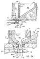
- Figure 2 and 2A are sectional view of an atomizer and tundish for practicing the invention.
- Figure 3 is sectional view of a collector for the sprayed melt.
- Figures 4A1 and 4B1 are photographs of as-sprayed IN718 nickel bsae superalloy material sprayed at 53.2 kPa (400 Torr) and 97.1 kPa (730 Torr), respectively, on an approximately) 51 cm (20 inch) diameter mandrel.
- Figures 4A2 and 4B2 are photomicrographs of the as-sprayed IN718 nickel base superalloy material sprayed at 53.2 kPa (400 Torr) and 97.1 kPa (730 Torr), respectively, showing grain size and porosity.
- the preforms depicted in Figures 4A1 and 4B1 were sprayed at an angle of 0 degrees (see angle AA of Figure 1; i.e. where the longitudinal axis of the collector is horizontal).
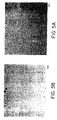
- Figures 5A and 5B are photomicrographs of electron beam weld heat affected zones of hot isostactically pressed spraycast Waspaloy nickel base superalloy material sprayed at 53.2 kPa (400 Torr) and 97.1 kPa (730 Torr), respectively, showing higher porosity at the weld heat affected zone for the sample sprayed at 97.1 kPa (730 Torr), Fig. 5B.
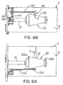
- Figure 6A is a side elevational view of a DC plasma heating torch useful in practicing an embodiment of the invention.
- Figure 6B is a plan view of the preheat torch of Figure 6A.
- Figure 6C is an end elevational view of the preheat torch of Figure 6A.
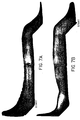
- Figure 7A, 7B are photographs of as-sprayed IN718 nickel base superalloy material sprayed at 97.1 kPa (730 Torr) on an approximately 51 cm (20 inch) diameter tapered collector surface at an angle of 45 degrees, Figure 7B, (see angle AA of Figure 1) as compared to Figure 7A of 25 degrees, wherein the central regions of the deposits were at 45 and 25 degree angles, respectvely, for Figs. 7A and 7B
- Figure 8A, 8B are photographs of as-sprayed IN718 nickel base superalloy material sprayed at 53.2 kPa (400 Torr) on an approximately 51 cm (20 inch) diameter tapered collector surface at an angle of 25 degrees (see angle AA of Figure 1), wherein the central regions of the deposits were at 25 degree angles for Figs. 8A, 8B.
- the spray deposits in Figs. 4B, 7 and 8 are shown cut into two pieces after spraying.
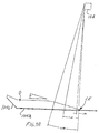
- Figure 9A illustrates the collector outer surface having a spray cast deposit thereon and the oscillation cycle comprisng incremental spray angles of the atomizing nozzle.
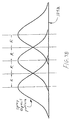
- Figure 9B illustrates the overlapping spray distribution collected on the collector outer surface as a result of the oscillation spray cycle.
- apparatus is schematically illustrated for spraycasting using the pressure control technique in accordance with an embodiment of the present invention.
- the apparatus comprises a vacuum melting chamber A and a spray chamber B in a walled chamber C.
- a refractory crucible 10 Disposed in the melting chamber A is a refractory crucible 10 in which a metal or alloy charge is melted by induction melting using induction coil 12 disposed about the crucible.
- the crucible 10 can be tilted about a crucible trunion T as shown to pour the metal or alloy melt at a proper superheat temperature into a refractory tundish 14.
- the tundish 14 includes a melt holding chamber 14b and a refractory melt discharge nozzle 14c defining a melt discharge orifice 14d (typical diameter of 6.35 - 7.62 mm (0.250-0.300 inch) such as 7.42 mm (0.292 inch) for IN 718 melt). Melt is discharged from the orifice 14d to an underlying atomizer means 18 disposed beneath the intermediate wall 19 separating the melting chamber A and the spray chamber B.
- the tundish functions to filter and control flow rate of the metal.
- the melting chamber A is communicated by conduit C1 to a conventional vacuum pump 20 that can evacuate the melting chamber A to very low vacuum levels, such as less than or equal to 1.33 Pa (10 micron Hg), prior to induction melting of the charge in the crucible 10. In this way, oxygen, nitrogen and other gases that could contaminate and/or react with the melt are removed from the chamber A prior to and during melting.
- spraycasting of a known nickel base superalloy IN 718 begins with charging the crucible 10 with bar stock of the IN 718 superalloy in the appropriate quantity needed.
- the crucible 10 comprises an alumina lined crucible that is substantially non-reactive with the melted IN 718 superalloy.
- the solid charge of the IN718 superalloy is induction melted in the crucible 10 by energizing the induction coils 12.
- the IN 718 melt is heated to an appropriate superheat above the alloy melting point (e.g. plus 93.3 to 149°C (200 to 300 degrees F) such as for example plus 149°C (300 degrees F) for IN 718 superalloy melt) prior to pouring.
- the melt temperature is measured by an infrared radiation (IR) pyrometer.
- IR infrared radiation
- both the melting chamber A and spray chamber B are backfilled with a partial pressure of inert or non-reactive gas to a level of 26.6 kPa (200 torr) to less than or equal to 53.2 kPa (400 torr) via gas discharged from atomizer 18 to be described or from gas sources S1 and/or S2, such as high pressure cylinders or bottles of inert (e.g. argon) or non-reactive gas, and valves V1, V2.
- Sources S1, S2 can be combined into a single gas source to this end to provide the gas to chambers A, B.
- the superheated melt is poured into preheated tundish 14.
- the tundish 14 includes an upstanding reticulated ceramic (zirconia) filter 17 having for example 10 to 20 pores per 2.54 cm (1 inch) that divides the tundish melt holding chamber 14b into a pour chamber 14g that receives the melt from the crucible 10 and a quiescent chamber 14h that is disposed above the melt discharge nozzle 14c to supply quiet melt thereto.
- the filter 17 acts to filter the alloy melt as it moves from pour chamber 14g to quiescent chamber 14h where the melt enters the melt discharge nozzle 14c and to diffuse turbulence from the pour chamber to the quiescent chamber.
- a thermocouple array 15 in the tundish records the tundish metal temperature during a spray run.
- the filter 17 is held fixed in lateral position in the tundish as shown by the filter width dimension being received in a cast-in complementary slot in the tundish and is held down vertically by a zirconia brick 17b.
- the filter 17 has an upper overflow channel 17a and a V-shaped bottom extending in a direction normal to the plane of the drawing with the apex of the shape cut off to promote drainage of the filter between pours of molten metal in the tundish and to concentrate drainage to this local filter region.
- the melt poured from the crucible 10 into the preheated tundish 14 is discharged from the melt discharge nozzle 14c having nozzle heater 14j disposed therearound.
- Flow rate of the melt from the discharge orifice 14d is controlled by maintaining an appropriate in-tundish metal head level.
- a typical flow rate for IN 718 superalloy melt can be in the range of 34 to 43 kg (75 to 95 pounds) per minute.
- the melt discharged from the tundish discharge orifice 14d flows to the atomizer means 18.
- Atomizer means 18 shown in Figures 2 and 2A for atomizing the melt is of the type described in U.S. Patent 4 779 802 and 4 905 899.
- Atomizer means 18 comprises a static primary gas nozzle 18a disposed about the melt discharge nozzle 14c.
- the primary gas nozzle 18a uses a primary gas such as an inert gas (e.g. argon) at a pressure in the range of 307.5 to 514 kPa (30 to 60 psig) supplied from manifold 19a to prevent splashback of the melt discharged from orifice 14d, a particular primary gas (argon) pressure for IN 718 melt being 342 kPa (35 psig) for splashback prevention.
- an inert gas e.g. argon
- the manifold 19a of the static gas nozzle 18a receives gas from a gas source 22 disposed outside the spray chamber B.
- the gas source can comprise conventional high pressure cylinders or bottles of inert gas, such as high purity argon, or other gas that is substantially non-reactive with the melt.
- Atomizer means 18 also comprises a scanning gas atomizer 18d that receives the atomized melt from the primary nozzle 18a and uses an atomizing gas such as an inert gas (e.g. argon) at an atomizing gas pressure in the range of 583 to 1064 kPa (70 to 140 psig) supplied from a gas manifold 21 for melt atomization, a particular secondary atomizing gas pressure for IN 718 superalloy melt being 858 kPa (110 psig).
- an inert gas e.g. argon
- the scanning atomizer 18d is termed a scanning atomizer because it oscillates in repeated cycles wherein each oscillation cycle includes oscillation through progressively increasing spray angles (relative to its vertical axis) as the collector 30 is axially moved and rotated at controlled rates relative to the atomizer 18d.
- the atomizer 18d can be operated through repeated cycles wherein each cycle includes oscillation through an angle of about 1, 7, and 13 degrees per one revolution of the collector starting from the vertical axis of the atomizer, Figures 9A. That is, the atomizer 18d will oscillate through a 1.06 degree range relative to the vertical axis for one revolution of the collector 30, then oscillate through a 7.41 degree range for one revolution of the collector, and then oscillate through a 13.58 degree range for one revolution of the collector 30.
- This cycle is repeated as the collector 30 is moved axially from a start deposition position to a finish deposition position in a single pass to form the desired sprayed deposit as a preform on the collector.
- the scanning cycle of the atomizer 18d embodying increasing oscillation angles for each revolution of the collector serves to overlap the sprayed deposit as a pattern schematically illustrated in Figure 9B in a uniform distribution over collector lengths limited only by the length of collector 30 in a single pass deposition operation; i.e. where the collector 30 is moved axially from right to the left in Figures 1 and 6 in a single pass relative to atomizer 18d to form the spray deposited preform on the collector surface 104a.
- so-called "sweet spots" of the spray deposit are generally equally spaced by distance R from one another on the collector surface to form a generally uniform spray deposit having the leading edge region shown oriented within 10 to 20 degrees (e.g. 15 degrees shown) to horizontal (or to an axis perpendicular to the spray axis of the atomizing nozzle 18d in the event a non-horizontal nozzle/collector orientation is used).
- the rpm of the collector 30 can be varied as a function of the outer diameter of collector surface 104a to minimize centrifugal stress on the spray cast deposit; e.g. so as not to exceed 137.6 kPa (20 psi).
- Oscillation of the atomizer 18d is slaved to the rpm of the collector 30 in that the approximate 1, 7, and 13 degree oscillation sequences will still occur over one revolution of the collector, regardless of the collector rpm, and then be repeated until the desired deposit is formed.
- the dwell time (spraying time) of each oscillation of the cycle thereby is lessened as the collector rotational speed (rpm) is increased.
- the manifold 21 of the scanning atomizer means 18d receives atomizing gas from a gas source 23 disposed outside the spray chamber B.
- the gas source can comprise conventional high pressure cylinders or bottles of inert gas, such as high purity argon, or other gas that is substantially non-reactive with the melt.
- the static gas nozzle 18a comprises a plurality (12) of gas discharge orifices 18f (diameter of 1.4 mm (0.055 inch)) spaced circumferentially about the melt discharge orifice 14d as shown in Figure 2A.
- the scannning gas atomizer 18d comprises a plurality (24) of gas discharge orifices 18i (diameter of 4 mm (0.1570 inch)) spaced circumferentially about the atomizer spray opening 18j as shown in Figure 2.
- the opening 18j and gas discharge orifices 18i of atomizer means 18 are relatively located effective to atomize the metal or alloy melt into a spray of fine molten droplets, an atomizer of use being described in U.S. Patent 4 779 802 and 4 905 899,
- the atomized metal or alloy spray S is directed at underlying mild steel substrate 104 of collector 30 disposed in the spray chamber B in the path of the spray S as shown in Figures 1.
- the collector 30 is mounted on double coaxial shaft mechanism, Figure 3, that rotates the collector and also moves the collector axially from an axial start deposition position to an axial finish deposition position relative to the atomizer 18d.
- the inner shaft 31 rotates via the bearing assembly shown between shafts 31, 33 of the collector while the outer shaft 33 mounts the collector 30 for axial motion relative to the atomizer 18d.
- a vacuum seal assembly 31b shown and bearing assembly shown are provided on the chamber double wall to this end.
- Rotary shaft 31 is driven in rotation by a AC servomotor 34.
- AC servomotor 34 and AC servomotor 32 are mounted on a common slide or carriage (not shown).
- AC servomotor 32 through a conventional ball/screw drive arrangement (not shown) drives the common slide or carriage on which motors 32, 34 are disposed for sliding motion together to impart axial motion to shaft 33 while shaft 31 rotates.
- the collector 30 includes external collector substrate surface 104a shaped to impart a desired shape to the spraycast metal or alloy deposited on the collector.
- Typical standoff distance between the collector outer surface 104a and the atomizer 18d is from 58.4 to 73.7 cm (23 to 29 inches) such as 66 cm (26 inches) for spraying IN 718 superalloy melt.
- the collector 30 can have a cylindrical outer collector surface 104a to form an annular or tubular deposit D having an inner and outer cylindrical collector surface 104a, such as required for a ring or tube.
- the collector surface 104a can be configured as a tapered cone, Figure 6, or any other shape to form the desired spray cast depsoit preform thereon.
- the collector 30 typically can be preheated prior to initiation of melt spraying by a static induction coil (not shown in Figure 1).
- the power and time of the collector preheating vary as a function of substrate size and geometry with the final preheat temperaure of the substrate typically being in the range of 927 to 982 °C (1700 degrees F to 1800 degrees F) for In 718 nickel base alloy.
- the DC plasma arc torch described below can be used in lieu of such induction preheating.
- the collector can comprise mild steel, although other materials can be used for the collector depending upon the metal or alloy being spraycast.
- Typical dimensions for a cylindrical collector outer surface 104a employed can include an outer diameter in the range of about 8.9 to 152 cm (3.5 inches to 60 inches)and a length of 152 cm (60 inches)having a usable spray length of about 142 cm (56 inches).
- the collector 30 is shown in more detail in Figure 3 as having a hollow tubular structure that comprises a simple, low-cost. construction, supports quick change manufacturing operations, permits insulation of the collector inner diameter, and accommodates thermal expansion of the collector.
- the collector 30 comprises axial substrate support end plates 100a, 100b and a stainless steel strongback 102 bearing the weight of the other collector components as well as concentrically positioning the end plates 100a, 100b and mild steel collector substrate 104 and its collector surface 104a relative to collector longitudinal axis.
- the strongback 102 is welded at its axial end 102a to hub 112.
- the tension ring 106 is fastened to the strongback by a tension ring fastening pin 106a that extends through appropriate diametral holes (not shown) in the tension ring and strongback 102 and by retaining clips 106b that retain the fastening pins in position at their ends.
- the left hand support end plate 100a is fastened to hub 112 by screws 114.
- the hub 112 in turn is fastened to an end hub 31a of the rotary shaft by a splne and bolt connection shown for rotation thereby.
- a vacuum o-ring pack assembly 31b provides a seal at the shaft 33.
- the diameters of the end plates 100a, 100b can be different to provide a tapered collector outer surface profile, Figure 6, in which the outer diameter of the substrate 104 decreases from one end to the other, or vice versa.
- Annular space 120 between the outer diameter of the strongback 102 and the inner diameter of the collector substrate 104 is filled with thermal insulation 122 (partially shown), such as Kaowool insulation, which helps to maintain the temperature of the substrate 104 to a sufficient degree to reduce or eliminate inner diameter fissure porosity during the spraying process; e.g. compare upper preform of Figure 8A sans insulation with lower preform of Figure 8B with insulation.
- thermal insulation 122 such as Kaowool insulation
- the collector 30 is rotated relative to the atomizer 18 during deposition of the spray S thereon by the drive motor and shaft 31 connecting the motor and collector 30.
- the spray S thereby can be deposited around the entire periphery or circumference of the collector outer surface 104a.
- the speed of rotation of the collector 30 typically is in the range of 100 to 200 rpm for IN 718 melt at af low rate of 34 to 43 kg (75 to 95 pounds) per minute.
- the speed of collector rotation is dictated by the allowable centrifugal stress on the deposit; e.g. to maintain the centrifugal stress to not exceed about 138 kPa (20 psi).
- the atomizer 18d oscillates through repeated cycles each comprising approximate 1, 7 and 13 degree oscillation for each revolution of the collector 30 as it is rotated and moved axially until the deposit is built up along the desired length of the collector.
- the collector preferably includes an angled peripheral "start" surface region 104b typically disposed proximate collector end plate 100a at which surface region spraying of the atomized. metal or alloy is started.
- the angled surface region 104b helps to catch sprayed material and form a "quick" build up of material at the region 104a (see Figs. 4 and 9A and "start” in Figs. 7 and 8) and conservation of material in the part envelope region. That is, without the collector region 104b, there will be a fall off or tapering off of the deposited material in a manner that is not useful to form the component, thus providing wasted material deposited on the collector.
- the surface region 104b can be disposed to also shield collector end plate 100a from molten metal spray.
- a similar angled surface region (not shown) can be provided proximate an opposite end plate 100b or other region of the collector 30 as for example was used to form the end region features of the deposits shown in Figures 7 and 8.
- the spray, chamber B is communicated by conduit C2 disposed opposite from the atomizer 18d to a vacuum pumping system that is capable of evacuating the spray chamber B at a high enough rate in order to maintain a selected low gas partial pressure (e.g. argon gas partial pressure when argon is the gas discharged from static atomizer 18a and scanning atomizer 18d) in the spray chamber B during spraycasting of the spray S onto the collector 30.
- a selected low gas partial pressure e.g. argon gas partial pressure when argon is the gas discharged from static atomizer 18a and scanning atomizer 18d
- the vacuum system must be capable of exhausting the argon gas from the spray chamber B at a rapid enough rate to maintain the selected low gas partial pressure in the spray chamber while the spray S is directed at and deposited onto the collector 30.
- the gas partial pressure in the spray chamber B is maintained at 53.2 kPa (400 torr) and below down to 1.3 kPa (10 torr).
- the gas partial pressure in chamber B is maintained from 33 kPa (250 torr) to less than 53.2 kPa (400 torr) using the vacuum system described below for spraycasting of superalloy melts, such as IN 718 superalloy melt.
- a suitable vacuum pumping system to achieve such gas partial pressure levels in the spray chamber B comprises first and second stage blowers (pumps) B1, B2 in series with an intercooler B3 disposed between the blowers to lower the heat of compression.
- the 1st stage blower B1 is a commercially available Stokes HPB 622 blower, while the 2nd stage blower B2 is a commercially available Hibbon SIAV 25 blower.
- the 1st and second stage blowers B1, B2 provide enough vacuum to overcome the atomizing gas flow at 757 kPa (110 psi) (i.e.
- the vacuum level in the spray chamber B is preset into a proportional integrative derivative controller CC (e.g. UDC 3000 controller from Honeywell Inc.) that automatically controls a modulation valve VV between the blowers B1, B2 and the spray chamber B.
- a proportional integrative derivative controller CC e.g. UDC 3000 controller from Honeywell Inc.
- the spray chamber B Prior to the atomized spray S being directed into the spray chamber at the collector 30, the spray chamber B is initally evacuated to less than 0.133 Pa (1 micron) in concert with evacuation of the melting chamber A by vacuum pump system 20 to remove oxygen, nitrogen and other unwanted gases. After the alloy is melted in crucible 10 under hard vacuum, the chambers A, B are backfilled with inert (e.g. high purity argon) or non-reactive gas in a range of 26.6 kPa (200 torr) to less than or equal to 53.2 kPa 400 torr gas partial pressure.
- inert e.g. high purity argon
- the backfill gas is provided from the atomizer 18 or gas source S1 and/or S2, such as high pressure cylinders or bottles of high purity inert or non-reactive gas, via valves V1 and/or V2.
- gas source S1 and/or S2 such as high pressure cylinders or bottles of high purity inert or non-reactive gas
- valves V1 and/or V2 A single common gas source (not shown) can be provided for the chambers A, B to this same end via a common valve (not shown).
- the melt is teamed or supplied to the atomizer 18 through the tundish 14, and the atomized spray S is directed at the preheated collector 30 for deposition thereon as a spraycast deposit with typical deposit thicknesses being in the range of 1.27 to 10.2 cm (0.5 inch to 4.0 inches).
- the collector 30 is rotated and moved axailly relative to atomizer 18d in a single pass to deposit the sprayed material to form the desired preform shape on the collector surface 104a.
- a typical typical ratio of atomizing gas-to-metal flow rate ratio used in practicing the invention especially for spray casting nickel base superalloys such as IN 718 is approximately 1.2 to 1, although the invention is not limited in this regard.
- An advantage of the invention is that the quality of the sprayed deposit does not appear to be as critically tied to gas to metal ratio as it is when the spray pressure in spray chamber B is near atmospheric.
- the collector 30 is rotated while the spray S is scanned at the collector 30 by scanning atomizer 18d in repeated cycles each including oscillation at approximate 1, 7, and 13 degrees.
- the vacuum pumps B1, B2 are operable to maintain the gas partial pressure (e.g. argon partial pressure if argon is the atomizing gas) at a low level preferably from 1.33 kPa (10 torr) to no greater than 53.2 kPa (400 torr).
- the collector 30 is preheated during spraying by a DC plasma torch or gun 130, Figures 6A, 6B, and 6C.
- a low pressure DC arc plasma preheat torch or gun is shown to actively heat the collector surface 104 just ahead of the leading edge LE of the deposit as it is formed; i.e. to provide an active in-situ substrate heating during deposition.
- the torch or gun 130 heats the substrate 104 just ahead of the deposit to 1) increase the bond between the deposit and substrate 104, 2) reduce inner diameter fissure porosity by maintaining a 927 to 982°C (1700 to 1800 degree F)deposit-to-interface thermal profile, and 3) allow for the focus of thermal energy at the leading edge of the deposit where the thermal energy is needed to these ends.
- the in-situ preheat of the collector substrate 104 by torch 130 in combination with the collector construction used having thermal insulation 122 yield a consistent inner diameter thermal profile with an attendant elimination of inner diameter fissure porosity in the deposit.
- the DC plasma arc torch or gun 130 comprises a typical conventional argon plus helium plasma gun typically used in vacuum plasma spray applications.
- the torch or gun is water cooled via suitable water lines 150 shown connected to the gun 130 and receives suitable plasma gas via suitable gas lines (not shown) connected to the gun.
- the aforementioned induction preheating technique can be used to heat the collector; however, induction preheating may only be used to preheat the collector prior to start of spraying whereas the DC plasma source technique can be used prior to and during the spraying.
- the torch or gun 130 is mounted on a slide mechanism shown in Figures 6a, 6B, and 6C residing in the spray chamber B.
- the slide mechanism carries a boom 142 which is part of the torch assembly.
- the boom 142 is carried on a slide 144 which is movable by servomotor 145 and ball/screw mechanism 146 in a direction parallel to the diameter of the collector 30 to permit the torch plume P to adjust in radial dimension to the profile of the sprayed deposit to be built up on the substrate surface 104 during spraying; e g. see Figure 6C.
- the torch 130 and collector 30 initially are positioned at the start deposition position on the collector 30 by axial movement of the double shaft mechanism.
- the torch 130 can be adjusted such that plasma plume is directed normal to the collector substrate surface 104a or at an angle thereto using a tapered collector surface as decsribed.
- the collector 30 is moved axially (from right to left in Figure 6B) during deposition, the plasma plume is directed just ahead of the deposit leading edge LE for the purposes described hereabove.
- the present invention envisions selecting the angle of leading edge region LE of the spray deposit, Figure 9A, to be at an acute angle to an axis perpendicular to the spray axis of the atomizing nozzle 18d to reduce inner diameter fissure porosity regardless of pressure in the spray chamber. This can be achieved by proper adjustment of the oscillation angles of the atomizing nozzle 18d. Alternately or in addition, the collector outer surface 104a (or alternately angle of the longitudinal axis of collector 30) can oriented to be off-horizontal to this end.
- the angle AA, Figure 1 of the collector surface 104a can be selected to be from 10 to 30 degrees such as 25 degrees relative to horiziontal (or other acute angle to horizontal) to improve the quality of the spray deposit by reducing inner diameter fissure porosity.
- spray cast IN 718 deposits on the collector 30 may be produced which have less than optimized inner diameter porosity; e.g.
- Adjustment of the angle AA of the collector surface 104a relative to horizontal can be effected by using a tapered collector substrate 104 as shown in Figure 6.
- the adjustment of the angle AA can be achieved by mounting the aforementioned double shaft mechanism and AC servomotors for the coaxial shafts 31, 33 in a manner to vary the angle of the shafts relative to horizontal to this same end.
- the deposited ring or tube typically of thickness from 1.27 to 10.2 cm (0.5 to 4.0 inches) is cooled in the spray chamber B under a relative vacuum.
- the spraycast ring or tube is removed from the collector 30 at ambinet temperature and then can be hot isotatically pressed to densify the deposited ring or tube.
- Maintaining of the low gas partial pressure in the spray chamber B in accordance with the invention provides improved control of the temperature of the atomized spray droplets in flight in the spray chamber B and of the atomized metal or alloy deposited on the collector 30 as well as in the reduction of as-sprayed porosity; e.g. see Figures 4B2 having 2.1 volume % porosity at a spray pressure of 97.1 kPa (730 torr) as compared Figure 4A2 having 0.9 volume % porosity at a spray pressure of 53.2 kPa (400 torr).
- the spray chamber pressure control technique provides a higher temperature of the atomized spray droplets in flight in the spray chamber B and as deposited on the collector by reducing droplet thermal convection heat loss that otherwise can occur at higher spray chamber pressures and by allowing thermal equilbrium conditions to be established more quickly in the deposited metal or alloy on the collector 30.
- Figure 4 illustrates the difference in spray-deposited IN 718 ring made at the low pressure (e.g. 53.2 kPa (400 torr)) in spray chamber B pursuant to the invention, Figure 4A1, versus a spray-deposited IN 718 ring made at much higher pressure (e.g. 97.1 kPa (730 torr)) in spray chamber B, Figure 4B1.
- the fissure porosity at the inner diameter (inner diameter of ring proximate the collector 30) and entrapped gas porosity within the ring deposit are both significantly reduced while the same uniform grain size (e.g. ASTM 6-6.5 grain size) is maintained in each ring microstructure without grain banding or layering.
- Figure 4A2 and Figure 4B2 illustrate microstructures of the spray rings of Figure 4A1 and 4B1, respectively.
- Entrapped argon in the spray deposit pursuant to the invention is significantly reduced (e.g. 0.9 volume % porosity) as compared to entrapped argon in the spray deposit made at the higher 97.1 kPa (730 torr) spary atmophere (e.g. 2.1 volume% porosity).
- entrapped argon in Waspaloy spray cast rings pursuant to the invention exhibit 0.5 ppm by weight Ar as compared to entrapped argon of 1.5 ppm by weight Ar in Waspaloy spray cast rings spray cast near atmopheric pressure in the spray chamber B.
- Figure 5 illustrates a lower electron beam weld porosity in a spray-deposited Waspaloy ring made at the low pressure (e.g. 400 torr) in spray chamber B pursuant to the invention, Figure 5A, as compared to electron weld porosity spray-deposited Waspaloy ring made at much higher pressure (e.g. 97.1 kPa (730 torr)) in spray chamber B, Figure 5B.
- the spray chamber pressure control technique reduces entrapped atomizing gas (as porosity) in the metal or alloy deposited on the collector 30, reduces fissure voids at the inner surface of the deposit immediately adjacent the collector outer surface 30a, and provides a substantially uniform grain size across the thickness of the deposit on the collector 30 as a result of improved thermal equilbrium conditions established in the deposit during spray deposition. Still further, larger diameter ring or tube deposits can be built up on the collector 30; e.g. deposits having a diameter greater than about 76.2 cm (30 inches) while avoiding grain layering or banding in the deposit can be achieved.
- Spraycasting at 53.2 kPa (400 torr) or less pursuant to the invention versus 730 torr as used heretofore also allows for scalability of the method and apparatus to make larger diameter preforms (deposits) as the convective cooling is lessened with an attendant increase in spray and deposit temperature.
- Higher spray/deposit temperatures allow for spraying larger diameter preforms at slower rotational speeds (i.e. reduced centrifugal stresses) while maintaining acceptable thermal profiles even at the larger diameters effective to reduce inner diameter fissure porosity and broaden the processing window.
- Spraycasting at 53.2 kPa (400 torr) or less pursuant to the invention reduces inner diameter fissure porosity, reduces entrapped gas in the deposit, and broadens the processing window to produce a variety of component shapes and sizes with uniform deposit microstructure. Further, control of the substrate angle pursuant to an embodiment of the invention also reduces inner diameter fissure porosity and and broadens the processing window to produce a variety of component shapes and sizes with uniform deposit microstructure.
- Use of the scanning atomizer cycle described above, of the thermally insulated collector, and DC plasma arc torch pursuant to other embodiments of the invention also reduce inner diameter fissure porosity and and broaden the processing window to produce a variety of component shapes and sizes with uniform deposit microstructure.
- the present invention thus can produce spray deposited rings and tubes having reduced inner diameter fissures and porosity as compared to spray deposition at the higher (e.g. 97.1 kPa (730 torr)) pressure while retaining uniform grain size across the thickness of the spray deposit with no grain banding.
Landscapes
- Chemical & Material Sciences (AREA)
- Engineering & Computer Science (AREA)
- Mechanical Engineering (AREA)
- Physics & Mathematics (AREA)
- Plasma & Fusion (AREA)
- Chemical Kinetics & Catalysis (AREA)
- Materials Engineering (AREA)
- Metallurgy (AREA)
- Organic Chemistry (AREA)
- Coating By Spraying Or Casting (AREA)
- Nozzles (AREA)
- Powder Metallurgy (AREA)
Description
it as a spray of molten droplets into the spray chamber having an initial (backfilled) inert or non-reactive gas partial pressure of 53.2 kPa (400 torr) or less therein. Thereafter, the gas partial pressure in the spray chamber is maintained at 53.2 kPa (400 torr) or less during spray deposition of the atomized spray on the collector by in-situ evacuation of the spray chamber to remove the atomizing gas introduced therein from the atomized spray. For spray cast articles, such as rings and tubes, having rotational symmetry, the collector can be rotated and moved in a single pass relative to the atomizing device to build up a spray deposit thereon.
Claims (11)
- Method of making a metallic article by spraycasting an atomized melt of a metal or metal alloy onto a collector (30), comprising:evacuating a spray chamber (B) accommodating said collector (30);filling the spray chamber with a gas being inert or non-reactive to said melt;atomizing the melt by a pressurized atomizing gas being inert or non-reactive to said melt, and directing the so obtained spray (S) of atomized melt and atomizing gas at said collector (30), andcontrolling the temperature of said spray (S) of atomized melt in flight in the spray chamber (B) and of the atomized metal or metal alloy as it is deposited on the collector (30) by evacuating the spray chamber as said spray (S) is directed at the collector to remove the atomizing gas using a vacuum pumping system (B1, B2, B3, VV, CC) to provide and maintain the spray chamber at a vacuum of 26.6 to 53,2 kPa (200 torr to 400 torr) during spraying to reduce fissure porosity of the deposit proximate the collector and to obtain a substantially uniform grain size across the thickness of the deposit.
- The method of claim 1, wherein the initial partial pressure of inert or non-reactive gas in the spray chamber is 53,2 kPa (400 torr) or less.
- The method of claim 1 or 2, wherein the spray chamber is maintained at a vacuum of 26.6 kPa (200 torr) to less than 53.2 kPa (400 torr).
- The method of one of claims 1 or 2, wherein the partial pressure of the atomizing gas in the spray chamber is maintained between 1,33 kPa (10 torr), preferably between 33,24 kPa (250 torr), and less than 53,2 kPa (400 torr) as the spray is directed at the collector.
- The method of one of claims 1 to 4, wherein the collector is rotated as the spray is directed thereat.
- The method of one of claims 1 to 5, wherein the temperature of the spray in the spray chamber and of the atomized metal or alloy deposited on the collector is maintained higher as compared to their temperature in the event the spray chamber would be maintained near atmospheric pressure.
- The method of one of claims 1 to 6, further including controlling temperature of the spray in flight in the spray chamber and of the atomized metal or alloy as it is deposited on the collector to reach thermal equilibrium in the deposit on the collector from an inner region to an outer region of the deposit such that grain layering or grain banding is reduced in the deposit.
- The method of one of claims 1 to 6, further including controlling temperature of the spray in flight in the spray chamber and of the atomized metal or alloy as it is deposited on the collector to reach thermal equilibrium in the deposit on the collector from an inner region to an outer region of the deposit such that a substantially uniform grain size Is provided between said inner region and outer region.
- The method of one of claims 1 to 8, further including controlling temperature of the deposit by heat retention in the deposit by virtue of its thickness.
- The method of one of claims 1 to 9, including collecting the spray on the collector to build up a deposit having a wall thickness greater than about 5 cm (2 inches) and avoiding grain layering or banding in the deposit.
- A spray cast metallic tubular article having an Inner diameter made by the method of one of claims 1 to 10 with substantially reduced Inner diameter porosity.
Applications Claiming Priority (2)
| Application Number | Priority Date | Filing Date | Title |
|---|---|---|---|
| US763009 | 1996-12-10 | ||
| US08/763,009 US6296043B1 (en) | 1996-12-10 | 1996-12-10 | Spraycast method and article |
Publications (2)
| Publication Number | Publication Date |
|---|---|
| EP0848078A1 EP0848078A1 (en) | 1998-06-17 |
| EP0848078B1 true EP0848078B1 (en) | 2002-09-25 |
Family
ID=25066648
Family Applications (1)
| Application Number | Title | Priority Date | Filing Date |
|---|---|---|---|
| EP97121391A Expired - Lifetime EP0848078B1 (en) | 1996-12-10 | 1997-12-05 | Spraycast method and article |
Country Status (4)
| Country | Link |
|---|---|
| US (1) | US6296043B1 (en) |
| EP (1) | EP0848078B1 (en) |
| JP (1) | JPH10216921A (en) |
| DE (1) | DE69715795T2 (en) |
Families Citing this family (26)
| Publication number | Priority date | Publication date | Assignee | Title |
|---|---|---|---|---|
| US6746225B1 (en) * | 1992-11-30 | 2004-06-08 | Bechtel Bwtx Idaho, Llc | Rapid solidification processing system for producing molds, dies and related tooling |
| US6063212A (en) * | 1998-05-12 | 2000-05-16 | United Technologies Corporation | Heat treated, spray formed superalloy articles and method of making the same |
| AT409348B (en) * | 1999-04-22 | 2002-07-25 | Thallner Erich | DEVICE FOR APPLYING MATERIALS TO SUBSTRATES, ESPECIALLY FOR PAINTING SI WAFERS |
| US6305459B1 (en) * | 1999-08-09 | 2001-10-23 | Ford Global Technologies, Inc. | Method of making spray-formed articles using a polymeric mandrel |
| AU3886401A (en) * | 1999-09-21 | 2001-04-24 | Hypertherm, Inc. | Process and apparatus for cutting or welding a workpiece |
| US6883581B2 (en) * | 2001-11-27 | 2005-04-26 | Ford Motor Company | Method and arrangement for implementing heat treatment during the execution of spray-form techniques |
| US7026016B2 (en) * | 2004-01-02 | 2006-04-11 | Bauer Eric C | Method of fabricating free standing objects using thermal spraying |
| US20070295833A1 (en) * | 2005-01-07 | 2007-12-27 | Tsuyoshi Oda | Thermal Spraying Nozzle Device and Thermal Spraying System |
| DE102006051936B4 (en) * | 2006-11-01 | 2014-03-20 | Zollern Bhw Gleitlager Gmbh & Co. Kg | Process for producing two interconnected layers and functional component which can be produced by the process |
| US7601399B2 (en) * | 2007-01-31 | 2009-10-13 | Surface Modification Systems, Inc. | High density low pressure plasma sprayed focal tracks for X-ray anodes |
| US8287966B2 (en) * | 2007-10-10 | 2012-10-16 | GM Global Technology Operations LLC | Spray cast mixed-material vehicle closure panels |
| US20110308760A1 (en) * | 2009-02-09 | 2011-12-22 | Hisamune Tanaka | Apparatus for production of metallic slab using electron beam, and process for production of metallic slab using the apparatus |
| US9267184B2 (en) | 2010-02-05 | 2016-02-23 | Ati Properties, Inc. | Systems and methods for processing alloy ingots |
| US10207312B2 (en) | 2010-06-14 | 2019-02-19 | Ati Properties Llc | Lubrication processes for enhanced forgeability |
| EP2718101A4 (en) * | 2011-06-08 | 2015-12-02 | Univ Virginia Patent Found | SUPERHYDROPHOBIC NANOCOMPOSITE COATINGS |
| US9027374B2 (en) * | 2013-03-15 | 2015-05-12 | Ati Properties, Inc. | Methods to improve hot workability of metal alloys |
| CN103894610B (en) * | 2014-04-18 | 2017-03-01 | 机械科学研究总院先进制造技术研究中心 | A kind of controllable temperature forming platform system |
| DE102014220180A1 (en) * | 2014-10-06 | 2016-06-09 | Siemens Aktiengesellschaft | Monitoring and controlling a coating process based on a heat distribution on the workpiece |
| CN105345001B (en) * | 2015-12-01 | 2017-12-19 | 吉林大学 | Nail-plate 3D printer built in a kind of orthopaedics titanium alloy |
| CN105397088A (en) * | 2015-12-16 | 2016-03-16 | 吉林大学 | Laser sintering and 3DP comprehensive 3D printing processing system and printing method |
| BR112019007190B1 (en) * | 2016-10-11 | 2022-11-01 | Effusiontech IP Pty Ltd | METHOD FOR FORMING 3D OBJECTS |
| CN107639828B (en) * | 2017-10-11 | 2024-05-28 | 安溪县贤彩茶叶机械有限公司 | A protective gas circulation device suitable for 3D printing |
| NL2021507B1 (en) * | 2018-08-28 | 2020-03-09 | Space Xyz B V | Assembly and method for producing metal powder |
| CN112410730B (en) * | 2020-11-21 | 2022-11-18 | 浙江曜创科技有限公司 | Coating equipment for semiconductor production |
| EP4259361A1 (en) * | 2020-12-08 | 2023-10-18 | Danmarks Tekniske Universitet | Powder manufacturing for powder metallurgy |
| CN113502446B (en) * | 2021-05-27 | 2023-07-28 | 中国航发南方工业有限公司 | Quick-turn and quick-change spraying protection clamp and spraying method |
Family Cites Families (20)
| Publication number | Priority date | Publication date | Assignee | Title |
|---|---|---|---|---|
| US2639490A (en) * | 1948-08-12 | 1953-05-26 | Joseph B Brennan | Formation of metal strip under controlled pressures |
| BE790453A (en) | 1971-10-26 | 1973-02-15 | Brooks Reginald G | MANUFACTURE OF METAL ARTICLES |
| GB1455862A (en) | 1973-11-06 | 1976-11-17 | Nat Res Dev | Spraying atomised particles |
| US4064295A (en) | 1973-11-06 | 1977-12-20 | National Research Development Corporation | Spraying atomized particles |
| GB1517283A (en) | 1974-06-28 | 1978-07-12 | Singer Alec | Production of metal articles |
| US4066117A (en) | 1975-10-28 | 1978-01-03 | The International Nickel Company, Inc. | Spray casting of gas atomized molten metal to produce high density ingots |
| US4420441A (en) | 1982-02-23 | 1983-12-13 | National Research Development Corp. | Method of making a two-phase or multi-phase metallic material |
| GB8306428D0 (en) | 1983-03-09 | 1983-04-13 | Singer A R E | Metal-coating metallic substrate |
| GB8311167D0 (en) | 1983-04-25 | 1983-06-02 | Jenkins W N | Directed spray |
| GB8405982D0 (en) | 1984-03-07 | 1984-04-11 | Singer A R E | Making metal strip and slab from spray |
| GB8420699D0 (en) | 1984-08-15 | 1984-09-19 | Singer A R E | Flow coating of metals |
| GB8507647D0 (en) * | 1985-03-25 | 1985-05-01 | Osprey Metals Ltd | Manufacturing metal products |
| DE3667496D1 (en) | 1985-03-25 | 1990-01-18 | Osprey Metals Ltd | METHOD FOR PRODUCING METALLIC PRODUCTS. |
| DE3664487D1 (en) | 1985-04-19 | 1989-08-24 | Nat Res Dev | Metal forming |
| DE3681732D1 (en) | 1985-11-12 | 1991-10-31 | Osprey Metals Ltd | PRODUCING LAYERS BY SPRAYING LIQUID METALS. |
| GB8527852D0 (en) | 1985-11-12 | 1985-12-18 | Osprey Metals Ltd | Atomization of metals |
| DE3683610D1 (en) | 1985-11-12 | 1992-03-05 | Osprey Metals Ltd | PRODUCING LAYERS BY SPRAYING LIQUID METALS. |
| US4905899A (en) | 1985-11-12 | 1990-03-06 | Osprey Metals Limited | Atomisation of metals |
| JP3170269B2 (en) * | 1988-06-06 | 2001-05-28 | オスピレイ.メタルス.リミテッド | Spray deposition |
| US5669433A (en) * | 1995-09-08 | 1997-09-23 | Aeroquip Corporation | Method for creating a free-form metal three-dimensional article using a layer-by-layer deposition of a molten metal |
-
1996
- 1996-12-10 US US08/763,009 patent/US6296043B1/en not_active Expired - Fee Related
-
1997
- 1997-12-05 EP EP97121391A patent/EP0848078B1/en not_active Expired - Lifetime
- 1997-12-05 DE DE69715795T patent/DE69715795T2/en not_active Expired - Fee Related
- 1997-12-10 JP JP9361936A patent/JPH10216921A/en active Pending
Also Published As
| Publication number | Publication date |
|---|---|
| EP0848078A1 (en) | 1998-06-17 |
| US6296043B1 (en) | 2001-10-02 |
| JPH10216921A (en) | 1998-08-18 |
| DE69715795T2 (en) | 2003-05-28 |
| DE69715795D1 (en) | 2002-10-31 |
Similar Documents
| Publication | Publication Date | Title |
|---|---|---|
| US6296043B1 (en) | Spraycast method and article | |
| EP3131684B1 (en) | Process for producing a preform using cold spray | |
| EP0852976B1 (en) | Method and apparatus for spraycasting | |
| EP0225080B1 (en) | Atomisation of metals | |
| US5208431A (en) | Method for producing object by laser spraying and apparatus for conducting the method | |
| EP0404274A1 (en) | Production of tubular deposits | |
| JP3170269B2 (en) | Spray deposition | |
| JP3065305B2 (en) | Method of manufacturing large-diameter spray-molded article using auxiliary heating and apparatus used for the method | |
| US4853250A (en) | Process of depositing particulate material on a substrate | |
| JP2515522B2 (en) | Method and apparatus for producing spray deposition bar or ingot | |
| CN101332511B (en) | Injection device, spray forming atomization chamber and spray forming method thereof | |
| US4905899A (en) | Atomisation of metals | |
| US5401539A (en) | Production of metal spray deposits | |
| US5993509A (en) | Atomizing apparatus and process | |
| JP2012006037A (en) | Spray-forming deposition method | |
| RU2171160C1 (en) | Method for centrifugal spraying of metal and apparatus for performing the same | |
| CN1140767A (en) | Equipment and process for injection deposition | |
| EP0440706B1 (en) | Atomization of metals | |
| US5060713A (en) | Method of and apparatus for spraycasting | |
| CN222001858U (en) | A high-end metal billet preparation device combining suspension melting and spray forming | |
| CA1263062A (en) | Production of spray deposits | |
| SU1444311A1 (en) | Installation for coating glass articles | |
| CN117583615A (en) | A centrifugal disk atomization preparation device and method based on suspension smelting | |
| JPH0581663B2 (en) |
Legal Events
| Date | Code | Title | Description |
|---|---|---|---|
| PUAI | Public reference made under article 153(3) epc to a published international application that has entered the european phase |
Free format text: ORIGINAL CODE: 0009012 |
|
| AK | Designated contracting states |
Kind code of ref document: A1 Designated state(s): DE FR GB |
|
| AX | Request for extension of the european patent |
Free format text: AL;LT;LV;MK;RO;SI |
|
| RIN1 | Information on inventor provided before grant (corrected) |
Inventor name: DALAL, RANES P. Inventor name: VAN HEEST, JACK W. Inventor name: INGERSOLL, DAVID P. Inventor name: COOK, DAVID A. Inventor name: POTTER, DOUGLAS S. Inventor name: BOWEN, KIM E. |
|
| 17P | Request for examination filed |
Effective date: 19981202 |
|
| AKX | Designation fees paid |
Free format text: DE FR GB |
|
| RBV | Designated contracting states (corrected) |
Designated state(s): DE FR GB |
|
| 17Q | First examination report despatched |
Effective date: 19990928 |
|
| RBV | Designated contracting states (corrected) |
Designated state(s): DE FR GB |
|
| GRAG | Despatch of communication of intention to grant |
Free format text: ORIGINAL CODE: EPIDOS AGRA |
|
| GRAG | Despatch of communication of intention to grant |
Free format text: ORIGINAL CODE: EPIDOS AGRA |
|
| GRAH | Despatch of communication of intention to grant a patent |
Free format text: ORIGINAL CODE: EPIDOS IGRA |
|
| GRAH | Despatch of communication of intention to grant a patent |
Free format text: ORIGINAL CODE: EPIDOS IGRA |
|
| GRAA | (expected) grant |
Free format text: ORIGINAL CODE: 0009210 |
|
| AK | Designated contracting states |
Kind code of ref document: B1 Designated state(s): DE FR GB |
|
| REG | Reference to a national code |
Ref country code: GB Ref legal event code: FG4D |
|
| REF | Corresponds to: |
Ref document number: 69715795 Country of ref document: DE Date of ref document: 20021031 |
|
| ET | Fr: translation filed | ||
| PLBE | No opposition filed within time limit |
Free format text: ORIGINAL CODE: 0009261 |
|
| STAA | Information on the status of an ep patent application or granted ep patent |
Free format text: STATUS: NO OPPOSITION FILED WITHIN TIME LIMIT |
|
| 26N | No opposition filed |
Effective date: 20030626 |
|
| PGFP | Annual fee paid to national office [announced via postgrant information from national office to epo] |
Ref country code: GB Payment date: 20041104 Year of fee payment: 8 |
|
| PGFP | Annual fee paid to national office [announced via postgrant information from national office to epo] |
Ref country code: FR Payment date: 20041201 Year of fee payment: 8 |
|
| PGFP | Annual fee paid to national office [announced via postgrant information from national office to epo] |
Ref country code: DE Payment date: 20041230 Year of fee payment: 8 |
|
| PG25 | Lapsed in a contracting state [announced via postgrant information from national office to epo] |
Ref country code: GB Free format text: LAPSE BECAUSE OF NON-PAYMENT OF DUE FEES Effective date: 20051205 |
|
| PG25 | Lapsed in a contracting state [announced via postgrant information from national office to epo] |
Ref country code: DE Free format text: LAPSE BECAUSE OF NON-PAYMENT OF DUE FEES Effective date: 20060701 |
|
| GBPC | Gb: european patent ceased through non-payment of renewal fee |
Effective date: 20051205 |
|
| PG25 | Lapsed in a contracting state [announced via postgrant information from national office to epo] |
Ref country code: FR Free format text: LAPSE BECAUSE OF NON-PAYMENT OF DUE FEES Effective date: 20060831 |
|
| REG | Reference to a national code |
Ref country code: FR Ref legal event code: ST Effective date: 20060831 |