EP0847809A1 - Container liner and method - Google Patents
Container liner and method Download PDFInfo
- Publication number
- EP0847809A1 EP0847809A1 EP97309892A EP97309892A EP0847809A1 EP 0847809 A1 EP0847809 A1 EP 0847809A1 EP 97309892 A EP97309892 A EP 97309892A EP 97309892 A EP97309892 A EP 97309892A EP 0847809 A1 EP0847809 A1 EP 0847809A1
- Authority
- EP
- European Patent Office
- Prior art keywords
- paint
- lid
- container
- open
- disposable
- Prior art date
- Legal status (The legal status is an assumption and is not a legal conclusion. Google has not performed a legal analysis and makes no representation as to the accuracy of the status listed.)
- Granted
Links
Images


Classifications
-
- B—PERFORMING OPERATIONS; TRANSPORTING
- B05—SPRAYING OR ATOMISING IN GENERAL; APPLYING FLUENT MATERIALS TO SURFACES, IN GENERAL
- B05B—SPRAYING APPARATUS; ATOMISING APPARATUS; NOZZLES
- B05B7/00—Spraying apparatus for discharge of liquids or other fluent materials from two or more sources, e.g. of liquid and air, of powder and gas
- B05B7/24—Spraying apparatus for discharge of liquids or other fluent materials from two or more sources, e.g. of liquid and air, of powder and gas with means, e.g. a container, for supplying liquid or other fluent material to a discharge device
- B05B7/2402—Apparatus to be carried on or by a person, e.g. by hand; Apparatus comprising containers fixed to the discharge device
- B05B7/2481—Apparatus to be carried on or by a person, e.g. by hand; Apparatus comprising containers fixed to the discharge device with a flexible container for liquid or other fluent material
-
- B—PERFORMING OPERATIONS; TRANSPORTING
- B05—SPRAYING OR ATOMISING IN GENERAL; APPLYING FLUENT MATERIALS TO SURFACES, IN GENERAL
- B05B—SPRAYING APPARATUS; ATOMISING APPARATUS; NOZZLES
- B05B7/00—Spraying apparatus for discharge of liquids or other fluent materials from two or more sources, e.g. of liquid and air, of powder and gas
- B05B7/24—Spraying apparatus for discharge of liquids or other fluent materials from two or more sources, e.g. of liquid and air, of powder and gas with means, e.g. a container, for supplying liquid or other fluent material to a discharge device
- B05B7/2402—Apparatus to be carried on or by a person, e.g. by hand; Apparatus comprising containers fixed to the discharge device
- B05B7/2405—Apparatus to be carried on or by a person, e.g. by hand; Apparatus comprising containers fixed to the discharge device using an atomising fluid as carrying fluid for feeding, e.g. by suction or pressure, a carried liquid from the container to the nozzle
- B05B7/2408—Apparatus to be carried on or by a person, e.g. by hand; Apparatus comprising containers fixed to the discharge device using an atomising fluid as carrying fluid for feeding, e.g. by suction or pressure, a carried liquid from the container to the nozzle characterised by the container or its attachment means to the spray apparatus
- B05B7/241—Apparatus to be carried on or by a person, e.g. by hand; Apparatus comprising containers fixed to the discharge device using an atomising fluid as carrying fluid for feeding, e.g. by suction or pressure, a carried liquid from the container to the nozzle characterised by the container or its attachment means to the spray apparatus the container being pressurised
-
- Y—GENERAL TAGGING OF NEW TECHNOLOGICAL DEVELOPMENTS; GENERAL TAGGING OF CROSS-SECTIONAL TECHNOLOGIES SPANNING OVER SEVERAL SECTIONS OF THE IPC; TECHNICAL SUBJECTS COVERED BY FORMER USPC CROSS-REFERENCE ART COLLECTIONS [XRACs] AND DIGESTS
- Y10—TECHNICAL SUBJECTS COVERED BY FORMER USPC
- Y10S—TECHNICAL SUBJECTS COVERED BY FORMER USPC CROSS-REFERENCE ART COLLECTIONS [XRACs] AND DIGESTS
- Y10S239/00—Fluid sprinkling, spraying, and diffusing
- Y10S239/14—Paint sprayers
Definitions
- paint When painting with a hand held spray gun, paint may be supplied from a paint cup mounted on the spray gun or from a paint cup which is connected through a hose to the spray gun.
- the paint cup When the paint cup is attached to the spray gun, it commonly uses suction for feeding the paint to the gun.
- suction As atomization air flows through a nozzle assembly on the spray gun, it creates a reduced pressure which draws the paint from the paint cup to the nozzle where it is discharged and atomized by the air flow.
- the maximum fluid flow rate is limited since the suction which creates the fluid flow is a function of the atomization air flow rate. Consequently, the operator's flexibility in using the gun may be limited in certain application.
- it is possible to pressurize an attached paint cup in order to provide for positive pressure paint feed to the gun nozzle. This is particularly useful for spraying more viscous materials.
- Spray guns with attached paint cups are relatively easy to clean when painting is finished or when the paint colour is changed.
- these spray guns have some disadvantages. Since the paint cup is attached to the spray gun during use, the operator will have to hold the relatively heavy weight of the cup and the paint in the cup during spraying. If the painter is painting objects which require a large volume of paint or is painting for a very long time, the added weight may quickly tire the painter and possibly stress the painter's wrist.
- An alterative to using an attached paint cup is to use a remote pressurized paint cup which is attached through a hose to deliver paint under pressure to a hand held spray gun.
- the paint cup may be designed so that it can be either held in the operator's free hand during spraying or hooked on, for example, a ladder step.
- the paint hose may only be about 1 or 2 meters in length.
- a longer paint hose may connect the remote cup to the spray gun and the paint cup may be set on the ground.
- longer hoses require more solvent for cleaning during paint change or upon completion of painting.
- These spray guns can be more user friendly, since they reduce the weight that the operator must hold during spraying and the paint cup may be sized to hold a larger volume of paint.
- a method for using a pressurized liquid coating material container which has a removable container lid which when secured to said container closes an open container end, said lid mounting a paint feed tube which extends through said open container end to adjacent a bottom of said container when said lid is secured to said container, comprises the steps of:-
- the container subsequently called a paint cup has a lid or cover which is secured to the cup either with a threaded ring which engages complementary threads on a paint cup rim or with a conventional clamping arrangement.
- the open end of the liner bag is folded over the upper end of the cup to protect the cup rim and any threads from paint during filling.
- the disposable lid and the disposable bag are thus clamped between the paint cup and the paint cup lid to prevent paint leakage between the disposable lid and bag.
- a paint feed tube is preferably pushed through a tight fitting opening in the disposable lid to extend to adjacent a bottom of the bag in the paint cup.
- an insert ring may be positioned in a recess in the disposable lid to hold the open disposable bag end away from threads on the paint cup as the paint cup lid is secured to the paint cup.
- the disposable lid preferably includes at least one vent opening for providing an air passage between the paint in the paint cup liner and the space between the disposable lid and the paint cup lid.
- the paint cup lid is removed, withdrawing the paint feed tube from the liner cover.
- the liner cover has a sufficiently tight fit with the paint feed tube to wipe paint from the exterior of the tube as it is withdrawn from the disposable lid.
- air pressure may be applied to the spray gun nozzle to purge any paint remaining in the spray gun and the connecting hose back into the liner so that it can be easily disposed of with the liner.
- the disposable liner and any remaining paint may be lifted from the paint cup and easily disposed of.
- the liner may, for example, be placed in a plastic bag which is sealed with a zipper closure for a mess free disposal.
- a disposable paint feed tube may be secured to the paint cup lid.
- the disposable paint feed tube will then remain with the disposable liner and lid when the paint cup lid is removed from the paint cup.
- the disposable paint cup liner has the benefit of reducing labor, cleaning solvent and disposal costs when cleaning the paint cup for a colour change, for other change in the type of paint being sprayed and when painting is completed.
- a disposable liner for a paint container including a paint cup having an open end and a lid adapted to be removably secured to and to close the open paint cup end, comprises a disposable bag adapted to line the paint cup and to have an open end which extends from the open paint cup end and is of a sufficiently large size to permit folding outwardly over the open paint cup end, a disposable lid adapted to engage the open paint cup end, said disposable lid having an opening adapted to receive and engage a paint feed tube on the paint cup lid and having at least one vent opening, said disposable lid having an annular step over which said open liner end may be folded, and an insert ring adapted to be inserted into said annular step to retain said open liner end folded over said step.
- the paint cup assembly 10 includes a paint cup 11 and a lid 12 which is secured to the paint cup 11 with a retainer ring 13.
- the retainer ring 13 is internally threaded to engage an externally threaded rim 14 on the paint cup for removably securing the paint cup lid 12 to the paint cup 11.
- the paint cup assembly 10 may be designed for setting on the floor during use, or for holding in the painter's free hand or for hanging from any available support.
- the lid 12 has an integral handle 15 for holding the paint cup assembly 10.
- An air hose fitting 16 is mounted on the handle 15 for connection to a conventional source of pressurized air (not shown). Pressurized air flows from the fitting 16 through a manually adjustable pressure setting valve 17 and into the interior of the paint cup 11. The air pressure in the paint cup 11 causes the paint to flow through a paint hose 18 to a conventional hand held spray gun (not shown).
- the pressurized air passages in the handle 15 also may be connected to an overpressure safety valve 19 and a pressure indicating gauge 20, both of which are downstream from the valve 17.
- a manual paint cup vent 21 is provided in the lid 12 for venting pressure within the paint cup 11 to facilitate removing the lid 12 from the paint cup 11.
- a hook 22 may be secured to the lid 12 for hanging the paint cup assembly 10 during spraying from any available support, such as a ladder step.
- the paint cup 11 is provided with a flat bottom 23 to permit standing the paint cup assembly 10 on any available flat surface, such as the floor or a work table.
- the paint hose 18 should be only as long as necessary. If the paint cup assembly 10 is to be hand held during painting, the paint hose 18 may only need to be 1 to 2 meters long. If the paint cup is to be set on the floor during use, the paint hose 18 will need to be significantly longer.
- a disposable liner is placed in the paint cup during spraying.
- the disposable liner is removed from the paint cup and is discarded.
- the pressurized air flow to the paint cup 11 may be shut off and the paint cup vent 21 opened to vent the paint cup to the atmosphere prior to removing the lid 12.
- air pressure may be applied to the spray gun nozzle to blow paint from the spray gun and the paint hose 18 back into the disposable liner in the paint cup 11. This paint will then be disposed of with the disposable liner.
- the liner and any paint remaining in the liner may be sealed in a plastic bag having a zipper closure for disposal to prevent paint spillage.
- the disposable paint cup liner and its use are illustrated in Figures 2-6.
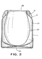
- the disposable paint cup liner includes a disposable bag 28 which is of a thin, flexible solvent tolerant material, such as polyethylene or a high density polyethylene (HDPE).
- the actual material used for the bag 28 may vary with the particular solvents in the coating material which will be placed in the bag 28.
- the bag 28 is inserted through an end opening 29 in the paint cup 11 and into an interior cavity 30 in the paint cup 11.
- the end opening 29 is defined by the paint cup rim 14.
- a sufficient portion of the disposable bag 28 is positioned in the cavity 30 so as to permit it to expand to the size of the cavity 30.
- the disposable bag 28 is sufficiently large as to have an open end 31 which extends from the open paint cup end 29.
- the disposable bag 28 may have a rectangular shape when flattened, or it may be shaped to more closely conform to the shape of the paint cup cavity 30 and the open paint cup end 29.
- the open bag end 31 is then folded outwardly and downwardly over the paint cup rim 14. In this position, the open bag end 31 protects the paint cup rim 14 from possible contamination with paint when the paint cup 11 is filled.
- Figure 3 shows the paint cup 11 and attached disposable bag 28 after a volume of paint 32 has been poured into the disposable bag 28.
- a disposable lid 33 is shown positioned on the paint cup rim 14.
- the disposable bag 28 and the disposable lid 33 together form the disposable liner 34.
- the disposable bag 28 extends radially outwardly between the paint cup rim 14 and a radial rim 35 on the disposable lid 33.
- the disposable lid 33 has a recessed portion 36 which extends slightly into the paint cup cavity 30 and closely engages the interior of the rim 14 for positioning the disposable lid 33 on the rim 14.
- the illustrated disposable lid 33 has in the recessed portion 36 an opening 37 for passing a paint feed tube 38 (shown only in Figure 6) and further may have a central recess 39 in which a vent opening 40 is formed.
- vent opening 40 is located at or near the center of the disposable lid 33, the risk of paint leaking through the vent opening 40 is minimized if the paint cup assembly 10 is tipped. However, since the paint cup assembly 10 is not attached to and tipped with a spray gun, the risk of leakage through vents in the disposable lid 33 is minimal. In place of a single central vent opening 40, a plurality of vent openings may be spaced around the disposable lid 33 at a radial distance from the center.
- the open end 31 of the disposable liner bag 28 is folded inwardly over the disposable lid rim 35.
- An optional insert ring 41 may be pushed into the recess 36 to hold the open bag end 31 in the inwardly folded position.
- the insert ring 41 may be circular in cross section or, as shown, may have a generally flat inner surface 42.
- the flat surface 42 aids in picking up the insert ring 41. It is preferable for the insert ring 41 to have a snug fit and not a press fit in the recessed portion 36 to facilitate inserting and removing the insert ring 41.
- the insert ring 41 functions to keep the open bag end 31 away from the threads on the paint cup rim 14 when the retainer ring 13 is secured to the threaded paint cup rim 14.
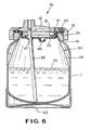
- FIG. 6 shows the paint cup lid 12 secured to the paint cup 11 to complete the paint cup assembly 10.
- the paint feed tube 38 is pushed through the disposable lid opening 37.
- the fit between the disposable lid opening 37 and the paint feed tube 38 is sufficiently snug to prevent paint leakage therebetween.
- the retainer ring 13 is secured to the threaded rim 14 to seal the paint cup 11.
- the open end 31 of the disposable bag 28 is wrapped around the disposable lid rim 35 and is clamped between the paint cup rim 14 and a resilient seal 43 on the paint cup lid 12.
- a seal is formed between the disposable bag 28 and the disposable lid 33.
- air pressure is delivered through the paint cup lid 12 to the space between the paint cup lid 12 and the disposable lid 33, it is free to flow through the vent opening 40 to force the paint 32 to flow through the paint feed tube 38 to the spray gun.
- the paint cup lid 12 may be removed from the paint cup 11.
- the paint feed tube 38 is withdrawn from the disposable lid opening 37, the exterior surface of the paint feed tube 38 is wiped clean to prevent dripping.
- the insert ring 41 will pop out of the recess 36.
- the open bag end 31 is then folded outwardly over the paint cup rim 14, the disposable lid 33 is removed from the paint cup 11 and additional paint 32 is added to the disposable bag 28 in the paint cup 11.
- the paint cup assembly 10 is then reassembled as described above.
- the paint cup 11 When painting with a particular paint is completed, the paint cup 11 may be vented to atmosphere and pressurized air may be used to force any paint remaining in the spray gun, the paint hose 18 and the paint feed tube 38 back into the disposable bag 28.
- the paint cup lid 12 is removed from the paint cup 11, withdrawing the paint feed tube 38, and the disposable liner 34 is disposed of.
- the disposable liner 34 and any remaining paint may be placed in a plastic bag (not shown) which is sealed with a zipper closure.
- the paint feed tube 38 also may be constructed of an inexpensive material and disposed of with the disposable liner 34. It is only necessary to clean the paint passages in the spray gun, in the paint hose 18 and in the paint cup lid 12. Consequently, the time, labor and solvent required for cleaning is reduced.
- the paint hose 18 and the paint feed tube 38 may be formed to be disposable as a unit with the disposable liner 34.
- the paint cup assembly 10 has been described with a retainer ring 13 for securing the lid 12 to the paint cup 11.
- Other conventional arrangements also may be used for securing the lid 12 to the paint cup 11.
- the threads on the paint cup rim 14 may be replaced with two or more projecting pins which are engaged by a known clamping mechanism on the lid 12.
Abstract
Description
Claims (5)
- A method for using a pressurized liquid coating material container (11) which has a removable container lid (12) which when secured to said container (11) closes an open container end, said lid mounting a paint feed tube (38) which extends through said open container end to adjacent a bottom of said container (11) when said lid (12) is secured to said container (11), said method comprising the steps of:-a) inserting a disposable liner bag (28) through said open container end (29) into said paint container (11), said liner bag (28) having an open bag end (31) which extends through said open container end (29) ;b) folding said open bag end (31) over said open container end (29) ;c) filling said liner bag (28) with a predetermined quantity of coating material (32) ;d) placing a disposable lid (33) over said open container end (29) in contact with said folded open bag end (31) ;e) folding said open bag end (31) inwardly over said disposable lid (33); and,f) securing said removable container lid (12) to said container (11), whereby said liner bag (28) and said disposable lid (33) are clamped between said open container end (29) and said removable container lid (12).
- A method for using a pressurized liquid coating material container, according to claim 1, and wherein said container (11) has external threads (14) adjacent said open container end (29) to which said container lid (11) is removably secured, and wherein said open bag end (31) is folded over said threads (14) prior to filling said liner bag (28) to protect said threads (14) from contact with coating material (32) during filing.
- A method for using a pressurized liquid coating material container, according to claim 1 or 2, wherein said disposable lid (33) has a circular recess (36), and, after said open bag end (31) is folded inwardly and prior to securing said removable container lid (12) to said container (11), further including the step of positioning a ring (41) to hold said open bag end (31) in said circular recess (36) to retain said open bag end (31) in its inwardly folded position while said removable container lid (12) is secured to said container (11).
- A method for using a pressurized liquid coating material container, according to any one of the preceding claims, wherein said disposable lid (33) has an opening (37) adapted to pass said material feed tube (38) while engaging an exterior surface of it, and further including the step of pushing said material feed tube (38) through said disposable lid opening (37) as said removable container lid (12) is secured to said container (11).
- A disposable liner for a paint container including a paint cup (11) having an open end (29) and a lid (12) adapted to be removably secured to and to close the open paint cup (11) end, said liner comprising a disposable bag (28) adapted to line the paint cup (11) and to have an open end (31) which extends from the open paint cup end (29) and is of a sufficiently large size to permit folding outwardly over the open paint cup end (29), a disposable lid (33) adapted to engage the open paint cup end (29), said disposable lid (33) having an opening (37) adapted to receive and engage a paint feed tube (38) on the paint cup lid (12) and having at least one vent opening (40), said disposable lid (33) having an annular step (36) over which said open liner end (31) may be folded, and an insert ring (40) adapted to be inserted into said annular step (36) to retain said open liner end (31) folded over said step (36) .
Applications Claiming Priority (2)
| Application Number | Priority Date | Filing Date | Title |
|---|---|---|---|
| US767339 | 1996-12-16 | ||
| US08/767,339 US5816501A (en) | 1996-12-16 | 1996-12-16 | Disposable paint container liner and method |
Publications (2)
| Publication Number | Publication Date |
|---|---|
| EP0847809A1 true EP0847809A1 (en) | 1998-06-17 |
| EP0847809B1 EP0847809B1 (en) | 2003-03-19 |
Family
ID=25079182
Family Applications (1)
| Application Number | Title | Priority Date | Filing Date |
|---|---|---|---|
| EP97309892A Expired - Lifetime EP0847809B1 (en) | 1996-12-16 | 1997-12-08 | Container liner and method |
Country Status (4)
| Country | Link |
|---|---|
| US (1) | US5816501A (en) |
| EP (1) | EP0847809B1 (en) |
| CA (1) | CA2219842C (en) |
| DE (1) | DE69719926D1 (en) |
Cited By (18)
| Publication number | Priority date | Publication date | Assignee | Title |
|---|---|---|---|---|
| WO2002085533A1 (en) * | 2001-04-24 | 2002-10-31 | 3M Innovative Properties Company | Reservoir with refill inlet for hand-held spray guns |
| US6938836B2 (en) | 2002-05-08 | 2005-09-06 | 3M Innovative Properties Company | Valve closure for spray gun reservoir |
| US7083119B2 (en) | 2003-09-25 | 2006-08-01 | 3M Innovative Properties Company | Security clip for spray gun connector |
| US7188785B2 (en) | 2001-04-24 | 2007-03-13 | 3M Innovative Properties Company | Reservoir with refill inlet for hand-held spray guns |
| WO2006086317A3 (en) * | 2005-02-08 | 2007-03-22 | 3M Innovative Properties Co | Pressurised paint supply cup comprising a liner and a bottom air inlet |
| WO2007079143A1 (en) * | 2005-12-30 | 2007-07-12 | 3M Innovative Properties Company | Liquid supply assembly and liquid spray apparatus |
| WO2007079188A2 (en) * | 2005-12-30 | 2007-07-12 | 3M Innovative Properties Company | Liquid supply assembly and liquid spray apparatus |
| WO2007149760A3 (en) * | 2006-06-20 | 2008-04-17 | Gerson Co Inc Louis M | Liquid supply assembly |
| US8127963B2 (en) | 2004-12-16 | 2012-03-06 | Saint-Gobain Abrasives, Inc. | Liquid container system for a spray gun |
| CN103350056A (en) * | 2013-07-10 | 2013-10-16 | 台州市桑妮气动工具有限公司 | Lower kettle for paint spraying |
| US8944351B2 (en) | 2011-05-06 | 2015-02-03 | Saint-Gobain Abrasives, Inc. | Paint cup assembly with an outlet valve |
| EP2771127A4 (en) * | 2011-10-27 | 2015-08-12 | Graco Minnesota Inc | Sprayer fluid supply with collapsible liner |
| US9586220B2 (en) | 2011-06-30 | 2017-03-07 | Saint-Gobain Abrasives, Inc. | Paint cup assembly |
| US9796492B2 (en) | 2015-03-12 | 2017-10-24 | Graco Minnesota Inc. | Manual check valve for priming a collapsible fluid liner for a sprayer |
| US10882064B2 (en) | 2011-12-30 | 2021-01-05 | Saint-Gobain Abrasives, Inc./Saint-Gobain Abrasifs | Convertible paint cup assembly with air inlet valve |
| US11040360B2 (en) | 2006-06-20 | 2021-06-22 | Saint-Gobain Abrasives, Inc. | Liquid supply assembly |
| WO2022074173A1 (en) * | 2020-10-09 | 2022-04-14 | J. Wagner Gmbh | Paint-spraying device for producing a paint spray jet and method for venting a paint container |
| US11707753B2 (en) | 2019-05-31 | 2023-07-25 | Graco Minnesota Inc. | Handheld fluid sprayer |
Families Citing this family (56)
| Publication number | Priority date | Publication date | Assignee | Title |
|---|---|---|---|---|
| US6820824B1 (en) | 1998-01-14 | 2004-11-23 | 3M Innovative Properties Company | Apparatus for spraying liquids, disposable containers and liners suitable for use therewith |
| WO2000067915A1 (en) * | 1999-05-07 | 2000-11-16 | Designetics | Automated priming station |
| EP1216758A1 (en) * | 2000-11-17 | 2002-06-26 | McLaws, Brent D. | Identifier label application system |
| US7143960B2 (en) * | 2001-03-14 | 2006-12-05 | 3M Innovative Properties Company | Liquid sample reservoir suitable for use with a spraying apparatus |
| GB0210446D0 (en) * | 2002-05-08 | 2002-06-12 | 3M Innovative Properties Co | Conformable pouch reservoir for spray gun |
| US7918369B2 (en) * | 2002-09-25 | 2011-04-05 | Illinois Tool Works Inc. | Two-component spray gun with solvent flush/blend |
| US7845582B2 (en) * | 2002-12-18 | 2010-12-07 | 3M Innovative Properties Company | Spray gun reservoir with oversize, fast-fill opening |
| US20040134917A1 (en) * | 2003-01-15 | 2004-07-15 | Lavern Carnegie | Paint tray liner |
| US6796514B1 (en) * | 2003-05-02 | 2004-09-28 | 3M Innovative Properties Company | Pre-packaged material supply assembly |
| US6945429B2 (en) * | 2003-06-10 | 2005-09-20 | Illinois Tool Works Inc. | Disposable paint cup attachment system for gravity-feed paint sprayer |
| FR2859118B1 (en) * | 2003-08-26 | 2007-03-09 | Michel Camilleri | DISPOSABLE BUCKET TO BE MOUNTED ON A GUN FOR THE PREPARATION, APPLICATION AND PRESERVATION OF A PAINT |
| CA2455182A1 (en) * | 2004-01-14 | 2005-07-14 | Charles Harland | Spray gun receptacle |
| US7165732B2 (en) | 2004-01-16 | 2007-01-23 | Illinois Tool Works Inc. | Adapter assembly for a fluid supply assembly |
| US7665672B2 (en) * | 2004-01-16 | 2010-02-23 | Illinois Tool Works Inc. | Antistatic paint cup |
| US7086549B2 (en) * | 2004-01-16 | 2006-08-08 | Illinois Tool Works Inc. | Fluid supply assembly |
| US7380680B2 (en) * | 2004-01-16 | 2008-06-03 | Illinois Tool Works Inc. | Fluid supply assembly |
| US7766250B2 (en) * | 2004-06-01 | 2010-08-03 | Illinois Tool Works Inc. | Antistatic paint cup |
| US7757972B2 (en) | 2004-06-03 | 2010-07-20 | Illinois Tool Works Inc. | Conversion adapter for a fluid supply assembly |
| US7353964B2 (en) | 2004-06-10 | 2008-04-08 | Illinois Tool Works Inc. | Fluid supply assembly |
| US20060021995A1 (en) * | 2004-07-30 | 2006-02-02 | Ralph Lavin | Storage and uncontaminated dispensing of fluids |
| US20060037960A1 (en) * | 2004-08-20 | 2006-02-23 | Rosa Wallace B | Paint tray cover and liner membrane |
| US7175110B2 (en) * | 2004-12-21 | 2007-02-13 | Anest Iwata Corporation | Manual spray gun and associated disposable cup |
| JP4965461B2 (en) | 2005-01-31 | 2012-07-04 | イリノイ トゥール ワークス インコーポレイティド | Fluid supply assembly with metering guide |
| US8393267B2 (en) | 2005-12-29 | 2013-03-12 | Illinois Tool Works, Inc. | Disposable cup insert for pad printing and decorating |
| EP2010337B1 (en) * | 2006-04-24 | 2013-12-04 | Millard F. Wallace | Paint tray and method of manufacture |
| US20100200596A1 (en) * | 2007-04-12 | 2010-08-12 | Wallace Millard F | Multilayer Thermoformable Materials and Shaped Articles and Containers Made Therefrom |
| US7891588B2 (en) * | 2006-05-31 | 2011-02-22 | Wagner Spray Tech Corporation | Quick disconnect for wetted parts in a paint spray gun |
| DE502007000825D1 (en) | 2006-12-05 | 2009-07-16 | Sata Gmbh & Co Kg | Ventilation for the gravity cup of a paint spray gun |
| EP2098458A1 (en) * | 2008-03-03 | 2009-09-09 | Superfos a/s | Container comprising an inner lining, a method of applying such a lining to a container and use of a peel able coating as an inner lining in a container |
| CA2717749C (en) | 2008-03-12 | 2014-06-03 | Jeffrey D. Fox | Disposable spray gun cartridge |
| DE202008014389U1 (en) | 2008-10-29 | 2010-04-08 | Sata Gmbh & Co. Kg | Gravity cup for a paint spray gun |
| US20100126998A1 (en) * | 2008-11-26 | 2010-05-27 | Corey Wilson | Food and Beverage Container with Integrated Disposable Liner Dispenser |
| DE102009032399A1 (en) | 2009-07-08 | 2011-01-13 | Sata Gmbh & Co. Kg | Spray Gun |
| DE202010007355U1 (en) | 2010-05-28 | 2011-10-20 | Sata Gmbh & Co. Kg | Nozzle head for a spraying device |
| EP2646166B1 (en) | 2010-12-02 | 2018-11-07 | SATA GmbH & Co. KG | Spray gun and accessories |
| CN107537707B (en) | 2011-06-30 | 2021-09-03 | 萨塔有限两合公司 | Spray gun, spray medium guide unit, cover, base body and related method |
| US9598208B2 (en) | 2013-08-15 | 2017-03-21 | Brannon K. Aki | Disposable bucket liner |
| CA155474S (en) | 2013-09-27 | 2015-08-27 | Sata Gmbh & Co Kg | Spray gun |
| MX2016007249A (en) | 2013-12-05 | 2017-01-05 | 3M Innovative Properties Co | Container for a spraying device. |
| DE202013105779U1 (en) | 2013-12-18 | 2015-03-19 | Sata Gmbh & Co. Kg | Air nozzle termination for a paint spray gun |
| USD758537S1 (en) | 2014-07-31 | 2016-06-07 | Sata Gmbh & Co. Kg | Paint spray gun rear portion |
| CN105289870B (en) | 2014-07-31 | 2019-09-24 | 萨塔有限两合公司 | Manufacturing method, spray gun, gun body and the lid of spray gun |
| CA159961S (en) | 2014-07-31 | 2015-07-17 | Sata Gmbh & Co Kg | Spray gun |
| USD768820S1 (en) | 2014-09-03 | 2016-10-11 | Sata Gmbh & Co. Kg | Paint spray gun with pattern |
| US9259960B1 (en) | 2014-09-03 | 2016-02-16 | Johnny Tepsi | Paint can assembly |
| WO2016141344A1 (en) * | 2015-03-05 | 2016-09-09 | Karcher North America, Inc. | Pressure washing system with selective fluid injection features |
| DE102015006484A1 (en) | 2015-05-22 | 2016-11-24 | Sata Gmbh & Co. Kg | Nozzle arrangement for a spray gun, in particular paint spray gun and spray gun, in particular paint spray gun |
| DE102015016474A1 (en) | 2015-12-21 | 2017-06-22 | Sata Gmbh & Co. Kg | Air cap and nozzle assembly for a spray gun and spray gun |
| CA3011425A1 (en) | 2016-01-15 | 2017-07-20 | 3M Innovative Properties Company | Modular spray gun lid assemblies and methods of design and use |
| CA3011437C (en) | 2016-01-15 | 2024-02-13 | 3M Innovative Properties Company | Spray gun cups, receptacles, lids, and methods of use |
| CN205995666U (en) | 2016-08-19 | 2017-03-08 | 萨塔有限两合公司 | Spray gun and its trigger |
| CN205966208U (en) | 2016-08-19 | 2017-02-22 | 萨塔有限两合公司 | Hood subassembly and spray gun |
| ES1166710Y (en) * | 2016-09-21 | 2017-01-03 | Sportshower S L | Portable dispenser |
| DE102018118738A1 (en) | 2018-08-01 | 2020-02-06 | Sata Gmbh & Co. Kg | Base body for a spray gun, spray guns, spray gun set, method for producing a base body for a spray gun and method for converting a spray gun |
| DE102018118737A1 (en) | 2018-08-01 | 2020-02-06 | Sata Gmbh & Co. Kg | Nozzle for a spray gun, nozzle set for a spray gun, spray guns and method for producing a nozzle for a spray gun |
| WO2018184636A2 (en) | 2018-08-01 | 2018-10-11 | Sata Gmbh & Co. Kg | Set of nozzles for a spray gun, spray gun system, method for embodying a nozzle module, method for seelcting a nozzle module from a set of nozzles for a paint job, selection system and computer program product |
Citations (8)
| Publication number | Priority date | Publication date | Assignee | Title |
|---|---|---|---|---|
| FR747268A (en) * | 1932-03-07 | 1933-06-14 | Applic Des Gaz Ind Liquides S | Transportable container for sprayer of paint or other liquids |
| US3227305A (en) * | 1963-08-09 | 1966-01-04 | Binks Mfg Co | Disposable liner |
| US3401842A (en) * | 1966-11-28 | 1968-09-17 | Betty L Morrison | Combination paint cup and filler for spray guns |
| US3432104A (en) * | 1967-03-23 | 1969-03-11 | Theodore L Kaltenbach | Seal spray gun siphon cup |
| US4043510A (en) * | 1975-11-21 | 1977-08-23 | Morris William E | Non-aerosol type dispenser |
| US4151929A (en) * | 1976-07-09 | 1979-05-01 | Sapien Sisto V | Plastic liner with collar for a paint receptacle |
| US4471911A (en) * | 1981-10-21 | 1984-09-18 | Hengesbach Robert W | Spraying apparatus and method |
| US4951875A (en) * | 1988-09-19 | 1990-08-28 | Devey Daniel A | Diposable liner system for spray guns |
Family Cites Families (6)
| Publication number | Priority date | Publication date | Assignee | Title |
|---|---|---|---|---|
| US2177032A (en) * | 1938-06-14 | 1939-10-24 | Baumgardner Henry Charles | Spraying device |
| USRE30968E (en) * | 1976-03-12 | 1982-06-15 | Champion Spark Plug Company | Attachment for paint spray gun systems |
| US5115943A (en) * | 1988-09-30 | 1992-05-26 | Fabricated Metals, Inc. | Bulk material container with a flexible liner |
| US5143294A (en) * | 1991-04-08 | 1992-09-01 | Lintvedt Arnold M | Pliant container for storage of a liquid and liquid application therefrom |
| US5143242A (en) * | 1991-04-25 | 1992-09-01 | Millasich David S | Paint bucket with disposable liner |
| CA2143277C (en) * | 1994-04-19 | 2000-05-16 | Michael J. Kosmyna | Hand held paint spray gun with top mounted paint cup |
-
1996
- 1996-12-16 US US08/767,339 patent/US5816501A/en not_active Expired - Lifetime
-
1997
- 1997-10-31 CA CA002219842A patent/CA2219842C/en not_active Expired - Lifetime
- 1997-12-08 EP EP97309892A patent/EP0847809B1/en not_active Expired - Lifetime
- 1997-12-08 DE DE69719926T patent/DE69719926D1/en not_active Expired - Lifetime
Patent Citations (8)
| Publication number | Priority date | Publication date | Assignee | Title |
|---|---|---|---|---|
| FR747268A (en) * | 1932-03-07 | 1933-06-14 | Applic Des Gaz Ind Liquides S | Transportable container for sprayer of paint or other liquids |
| US3227305A (en) * | 1963-08-09 | 1966-01-04 | Binks Mfg Co | Disposable liner |
| US3401842A (en) * | 1966-11-28 | 1968-09-17 | Betty L Morrison | Combination paint cup and filler for spray guns |
| US3432104A (en) * | 1967-03-23 | 1969-03-11 | Theodore L Kaltenbach | Seal spray gun siphon cup |
| US4043510A (en) * | 1975-11-21 | 1977-08-23 | Morris William E | Non-aerosol type dispenser |
| US4151929A (en) * | 1976-07-09 | 1979-05-01 | Sapien Sisto V | Plastic liner with collar for a paint receptacle |
| US4471911A (en) * | 1981-10-21 | 1984-09-18 | Hengesbach Robert W | Spraying apparatus and method |
| US4951875A (en) * | 1988-09-19 | 1990-08-28 | Devey Daniel A | Diposable liner system for spray guns |
Cited By (38)
| Publication number | Priority date | Publication date | Assignee | Title |
|---|---|---|---|---|
| JP2009131845A (en) * | 2001-04-24 | 2009-06-18 | Three M Innovative Properties Co | Reservoir with replenishment entrance for handy type spray gun |
| US7815130B2 (en) | 2001-04-24 | 2010-10-19 | 3M Innovative Properties Company | Reservoir with refill inlet for hand-held spray guns |
| US7188785B2 (en) | 2001-04-24 | 2007-03-13 | 3M Innovative Properties Company | Reservoir with refill inlet for hand-held spray guns |
| WO2002085533A1 (en) * | 2001-04-24 | 2002-10-31 | 3M Innovative Properties Company | Reservoir with refill inlet for hand-held spray guns |
| US6938836B2 (en) | 2002-05-08 | 2005-09-06 | 3M Innovative Properties Company | Valve closure for spray gun reservoir |
| US7172139B2 (en) | 2003-09-25 | 2007-02-06 | 3M Innovative Properties Company | Security clip for spray gun connector |
| US7789324B2 (en) | 2003-09-25 | 2010-09-07 | 3M Innovative Properties Company | Security clip for spray gun connector |
| US7083119B2 (en) | 2003-09-25 | 2006-08-01 | 3M Innovative Properties Company | Security clip for spray gun connector |
| US9162240B2 (en) | 2004-12-16 | 2015-10-20 | Saint-Gobain Abrasives, Inc./Saint-Gobain Abrasie | Liquid container system for a spray gun |
| US8127963B2 (en) | 2004-12-16 | 2012-03-06 | Saint-Gobain Abrasives, Inc. | Liquid container system for a spray gun |
| WO2006086317A3 (en) * | 2005-02-08 | 2007-03-22 | 3M Innovative Properties Co | Pressurised paint supply cup comprising a liner and a bottom air inlet |
| US7513443B2 (en) | 2005-02-08 | 2009-04-07 | 3M Innovative Properties Company | Pressurized liquid supply assembly |
| AU2006212918B2 (en) * | 2005-02-08 | 2010-07-29 | 3M Innovative Properties Company | Pressurised paint supply cup comprising a liner and a bottom air inlet |
| US7410106B2 (en) | 2005-02-08 | 2008-08-12 | 3M Innovative Properties Company | Pressurized liquid supply assembly |
| US8490892B2 (en) | 2005-02-08 | 2013-07-23 | 3M Innovative Properties Company | Pressurized liquid supply assembly |
| WO2007079188A2 (en) * | 2005-12-30 | 2007-07-12 | 3M Innovative Properties Company | Liquid supply assembly and liquid spray apparatus |
| WO2007079143A1 (en) * | 2005-12-30 | 2007-07-12 | 3M Innovative Properties Company | Liquid supply assembly and liquid spray apparatus |
| WO2007079188A3 (en) * | 2005-12-30 | 2007-08-30 | 3M Innovative Properties Co | Liquid supply assembly and liquid spray apparatus |
| EP2564937A1 (en) * | 2006-06-20 | 2013-03-06 | Saint-Gobain Abrasives, Inc. | Liquid supply assembly |
| US10035156B2 (en) | 2006-06-20 | 2018-07-31 | Saint-Gobain Abrasives, Inc. | Liquid supply assembly |
| US11679399B2 (en) | 2006-06-20 | 2023-06-20 | Saint-Gobain Abrasives, Inc. | Liquid supply assembly |
| US8033413B2 (en) | 2006-06-20 | 2011-10-11 | Saint-Gobain Abrastives, Inc. | Liquid supply assembly |
| WO2007149760A3 (en) * | 2006-06-20 | 2008-04-17 | Gerson Co Inc Louis M | Liquid supply assembly |
| US11548018B1 (en) | 2006-06-20 | 2023-01-10 | Saint-Gobain Abrasives, Inc. | Liquid supply assembly |
| US11040360B2 (en) | 2006-06-20 | 2021-06-22 | Saint-Gobain Abrasives, Inc. | Liquid supply assembly |
| US8944351B2 (en) | 2011-05-06 | 2015-02-03 | Saint-Gobain Abrasives, Inc. | Paint cup assembly with an outlet valve |
| US8998018B2 (en) | 2011-05-06 | 2015-04-07 | Saint-Gobain Abrasives, Inc. | Paint cup assembly with an extended ring |
| US9335198B2 (en) | 2011-05-06 | 2016-05-10 | Saint-Gobain Abrasives, Inc. | Method of using a paint cup assembly |
| US9586220B2 (en) | 2011-06-30 | 2017-03-07 | Saint-Gobain Abrasives, Inc. | Paint cup assembly |
| EP2771127A4 (en) * | 2011-10-27 | 2015-08-12 | Graco Minnesota Inc | Sprayer fluid supply with collapsible liner |
| CN107262308A (en) * | 2011-10-27 | 2017-10-20 | 固瑞克明尼苏达有限公司 | Sprayer fluid feed system with collapsible bushing pipe |
| US9174231B2 (en) | 2011-10-27 | 2015-11-03 | Graco Minnesota Inc. | Sprayer fluid supply with collapsible liner |
| US10882064B2 (en) | 2011-12-30 | 2021-01-05 | Saint-Gobain Abrasives, Inc./Saint-Gobain Abrasifs | Convertible paint cup assembly with air inlet valve |
| CN103350056A (en) * | 2013-07-10 | 2013-10-16 | 台州市桑妮气动工具有限公司 | Lower kettle for paint spraying |
| US9796492B2 (en) | 2015-03-12 | 2017-10-24 | Graco Minnesota Inc. | Manual check valve for priming a collapsible fluid liner for a sprayer |
| US10315787B2 (en) | 2015-03-12 | 2019-06-11 | Graco Minnesota Inc. | Manual check valve for priming a collapsible fluid liner for a sprayer |
| US11707753B2 (en) | 2019-05-31 | 2023-07-25 | Graco Minnesota Inc. | Handheld fluid sprayer |
| WO2022074173A1 (en) * | 2020-10-09 | 2022-04-14 | J. Wagner Gmbh | Paint-spraying device for producing a paint spray jet and method for venting a paint container |
Also Published As
| Publication number | Publication date |
|---|---|
| CA2219842C (en) | 2001-06-05 |
| MX9709762A (en) | 1998-07-31 |
| US5816501A (en) | 1998-10-06 |
| EP0847809B1 (en) | 2003-03-19 |
| DE69719926D1 (en) | 2003-04-24 |
| CA2219842A1 (en) | 1998-06-16 |
Similar Documents
| Publication | Publication Date | Title |
|---|---|---|
| EP0847809B1 (en) | Container liner and method | |
| EP1507596B1 (en) | Conformable pouch reservoir for spray gun | |
| EP1385632B1 (en) | Reservoir with refill inlet for hand-held spray guns | |
| CA2675563C (en) | Fluid supply assembly | |
| US7815130B2 (en) | Reservoir with refill inlet for hand-held spray guns | |
| CA2143277C (en) | Hand held paint spray gun with top mounted paint cup | |
| EP1961488B2 (en) | Apparatus for spraying liquids, and disposable containers and liners suitable for use therewith | |
| US7374111B2 (en) | Apparatus for spraying liquids, and disposable containers and liners suitable for use therewith | |
| EP1415719B1 (en) | Apparatus for spraying liquids, and disposable containers and liners suitable for use therewith | |
| WO2004037431A1 (en) | Spray gun with pressure assisted liquid supply cup comprising an inner liner | |
| MXPA97009762A (en) | Disposable liner for painting containers and method for use |
Legal Events
| Date | Code | Title | Description |
|---|---|---|---|
| PUAI | Public reference made under article 153(3) epc to a published international application that has entered the european phase |
Free format text: ORIGINAL CODE: 0009012 |
|
| AK | Designated contracting states |
Kind code of ref document: A1 Designated state(s): DE ES FR GB IE IT NL |
|
| AX | Request for extension of the european patent |
Free format text: AL;LT;LV;MK;RO;SI |
|
| 17P | Request for examination filed |
Effective date: 19981127 |
|
| AKX | Designation fees paid |
Free format text: DE ES FR GB IE IT NL |
|
| RBV | Designated contracting states (corrected) |
Designated state(s): DE ES FR GB IE IT NL |
|
| GRAG | Despatch of communication of intention to grant |
Free format text: ORIGINAL CODE: EPIDOS AGRA |
|
| 17Q | First examination report despatched |
Effective date: 20020523 |
|
| GRAG | Despatch of communication of intention to grant |
Free format text: ORIGINAL CODE: EPIDOS AGRA |
|
| GRAH | Despatch of communication of intention to grant a patent |
Free format text: ORIGINAL CODE: EPIDOS IGRA |
|
| GRAH | Despatch of communication of intention to grant a patent |
Free format text: ORIGINAL CODE: EPIDOS IGRA |
|
| GRAA | (expected) grant |
Free format text: ORIGINAL CODE: 0009210 |
|
| AK | Designated contracting states |
Designated state(s): DE ES FR GB IE IT NL |
|
| PG25 | Lapsed in a contracting state [announced via postgrant information from national office to epo] |
Ref country code: NL Free format text: LAPSE BECAUSE OF FAILURE TO SUBMIT A TRANSLATION OF THE DESCRIPTION OR TO PAY THE FEE WITHIN THE PRESCRIBED TIME-LIMIT Effective date: 20030319 Ref country code: IT Free format text: LAPSE BECAUSE OF FAILURE TO SUBMIT A TRANSLATION OF THE DESCRIPTION OR TO PAY THE FEE WITHIN THE PRESCRIBED TIME-LIMIT;WARNING: LAPSES OF ITALIAN PATENTS WITH EFFECTIVE DATE BEFORE 2007 MAY HAVE OCCURRED AT ANY TIME BEFORE 2007. THE CORRECT EFFECTIVE DATE MAY BE DIFFERENT FROM THE ONE RECORDED. Effective date: 20030319 |
|
| REG | Reference to a national code |
Ref country code: GB Ref legal event code: FG4D |
|
| REG | Reference to a national code |
Ref country code: IE Ref legal event code: FG4D |
|
| REF | Corresponds to: |
Ref document number: 69719926 Country of ref document: DE Date of ref document: 20030424 Kind code of ref document: P |
|
| PG25 | Lapsed in a contracting state [announced via postgrant information from national office to epo] |
Ref country code: DE Free format text: LAPSE BECAUSE OF FAILURE TO SUBMIT A TRANSLATION OF THE DESCRIPTION OR TO PAY THE FEE WITHIN THE PRESCRIBED TIME-LIMIT Effective date: 20030621 |
|
| NLV1 | Nl: lapsed or annulled due to failure to fulfill the requirements of art. 29p and 29m of the patents act | ||
| PG25 | Lapsed in a contracting state [announced via postgrant information from national office to epo] |
Ref country code: ES Free format text: LAPSE BECAUSE OF FAILURE TO SUBMIT A TRANSLATION OF THE DESCRIPTION OR TO PAY THE FEE WITHIN THE PRESCRIBED TIME-LIMIT Effective date: 20030930 |
|
| ET | Fr: translation filed | ||
| PLBE | No opposition filed within time limit |
Free format text: ORIGINAL CODE: 0009261 |
|
| STAA | Information on the status of an ep patent application or granted ep patent |
Free format text: STATUS: NO OPPOSITION FILED WITHIN TIME LIMIT |
|
| 26N | No opposition filed |
Effective date: 20031222 |
|
| PGFP | Annual fee paid to national office [announced via postgrant information from national office to epo] |
Ref country code: IE Payment date: 20041222 Year of fee payment: 8 |
|
| PG25 | Lapsed in a contracting state [announced via postgrant information from national office to epo] |
Ref country code: IE Free format text: LAPSE BECAUSE OF NON-PAYMENT OF DUE FEES Effective date: 20051208 |
|
| REG | Reference to a national code |
Ref country code: IE Ref legal event code: MM4A |
|
| REG | Reference to a national code |
Ref country code: GB Ref legal event code: 732E Free format text: REGISTERED BETWEEN 20120126 AND 20120201 |
|
| REG | Reference to a national code |
Ref country code: FR Ref legal event code: PLFP Year of fee payment: 19 |
|
| REG | Reference to a national code |
Ref country code: FR Ref legal event code: PLFP Year of fee payment: 20 |
|
| PGFP | Annual fee paid to national office [announced via postgrant information from national office to epo] |
Ref country code: GB Payment date: 20161228 Year of fee payment: 20 |
|
| PGFP | Annual fee paid to national office [announced via postgrant information from national office to epo] |
Ref country code: FR Payment date: 20161227 Year of fee payment: 20 |
|
| REG | Reference to a national code |
Ref country code: GB Ref legal event code: PE20 Expiry date: 20171207 |
|
| PG25 | Lapsed in a contracting state [announced via postgrant information from national office to epo] |
Ref country code: GB Free format text: LAPSE BECAUSE OF EXPIRATION OF PROTECTION Effective date: 20171207 |