EP0847257B1 - Hole caps for prosthetic implants - Google Patents
Hole caps for prosthetic implants Download PDFInfo
- Publication number
- EP0847257B1 EP0847257B1 EP95943068A EP95943068A EP0847257B1 EP 0847257 B1 EP0847257 B1 EP 0847257B1 EP 95943068 A EP95943068 A EP 95943068A EP 95943068 A EP95943068 A EP 95943068A EP 0847257 B1 EP0847257 B1 EP 0847257B1
- Authority
- EP
- European Patent Office
- Prior art keywords
- cap
- hole
- counter
- bored
- retaining
- Prior art date
- Legal status (The legal status is an assumption and is not a legal conclusion. Google has not performed a legal analysis and makes no representation as to the accuracy of the status listed.)
- Expired - Lifetime
Links
- 239000007943 implant Substances 0.000 title claims abstract description 38
- 210000000988 bone and bone Anatomy 0.000 claims abstract description 52
- 230000006835 compression Effects 0.000 claims abstract description 51
- 238000007906 compression Methods 0.000 claims abstract description 51
- 238000003780 insertion Methods 0.000 claims description 17
- 230000037431 insertion Effects 0.000 claims description 17
- 229910001069 Ti alloy Inorganic materials 0.000 claims description 3
- WAIPAZQMEIHHTJ-UHFFFAOYSA-N [Cr].[Co] Chemical class [Cr].[Co] WAIPAZQMEIHHTJ-UHFFFAOYSA-N 0.000 claims description 3
- 230000013011 mating Effects 0.000 claims description 3
- 230000004888 barrier function Effects 0.000 abstract description 3
- 239000011799 hole material Substances 0.000 description 147
- 239000002639 bone cement Substances 0.000 description 18
- -1 polyethylene Polymers 0.000 description 13
- 239000004698 Polyethylene Substances 0.000 description 12
- 229920000573 polyethylene Polymers 0.000 description 12
- 239000000463 material Substances 0.000 description 9
- 238000004519 manufacturing process Methods 0.000 description 7
- 229910052751 metal Inorganic materials 0.000 description 6
- 239000002184 metal Substances 0.000 description 6
- 239000004568 cement Substances 0.000 description 5
- 239000002245 particle Substances 0.000 description 4
- 210000002303 tibia Anatomy 0.000 description 4
- 238000000034 method Methods 0.000 description 3
- 230000002028 premature Effects 0.000 description 3
- 229910000684 Cobalt-chrome Inorganic materials 0.000 description 2
- 239000010952 cobalt-chrome Substances 0.000 description 2
- 238000003754 machining Methods 0.000 description 2
- 230000007246 mechanism Effects 0.000 description 2
- 229920003023 plastic Polymers 0.000 description 2
- 239000004033 plastic Substances 0.000 description 2
- 238000003825 pressing Methods 0.000 description 2
- 230000004044 response Effects 0.000 description 2
- 230000000153 supplemental effect Effects 0.000 description 2
- 238000001356 surgical procedure Methods 0.000 description 2
- 208000006386 Bone Resorption Diseases 0.000 description 1
- 241001653121 Glenoides Species 0.000 description 1
- 229910000831 Steel Inorganic materials 0.000 description 1
- 238000005452 bending Methods 0.000 description 1
- 230000008901 benefit Effects 0.000 description 1
- 230000024279 bone resorption Effects 0.000 description 1
- 238000004140 cleaning Methods 0.000 description 1
- 230000002542 deteriorative effect Effects 0.000 description 1
- 230000000694 effects Effects 0.000 description 1
- 238000001727 in vivo Methods 0.000 description 1
- 238000012986 modification Methods 0.000 description 1
- 230000004048 modification Effects 0.000 description 1
- 230000000010 osteolytic effect Effects 0.000 description 1
- 230000008569 process Effects 0.000 description 1
- 239000010959 steel Substances 0.000 description 1
Images






Classifications
-
- A—HUMAN NECESSITIES
- A61—MEDICAL OR VETERINARY SCIENCE; HYGIENE
- A61F—FILTERS IMPLANTABLE INTO BLOOD VESSELS; PROSTHESES; DEVICES PROVIDING PATENCY TO, OR PREVENTING COLLAPSING OF, TUBULAR STRUCTURES OF THE BODY, e.g. STENTS; ORTHOPAEDIC, NURSING OR CONTRACEPTIVE DEVICES; FOMENTATION; TREATMENT OR PROTECTION OF EYES OR EARS; BANDAGES, DRESSINGS OR ABSORBENT PADS; FIRST-AID KITS
- A61F2/00—Filters implantable into blood vessels; Prostheses, i.e. artificial substitutes or replacements for parts of the body; Appliances for connecting them with the body; Devices providing patency to, or preventing collapsing of, tubular structures of the body, e.g. stents
- A61F2/02—Prostheses implantable into the body
- A61F2/30—Joints
- A61F2/30721—Accessories
- A61F2/30744—End caps, e.g. for closing an endoprosthetic cavity
-
- A—HUMAN NECESSITIES
- A61—MEDICAL OR VETERINARY SCIENCE; HYGIENE
- A61F—FILTERS IMPLANTABLE INTO BLOOD VESSELS; PROSTHESES; DEVICES PROVIDING PATENCY TO, OR PREVENTING COLLAPSING OF, TUBULAR STRUCTURES OF THE BODY, e.g. STENTS; ORTHOPAEDIC, NURSING OR CONTRACEPTIVE DEVICES; FOMENTATION; TREATMENT OR PROTECTION OF EYES OR EARS; BANDAGES, DRESSINGS OR ABSORBENT PADS; FIRST-AID KITS
- A61F2/00—Filters implantable into blood vessels; Prostheses, i.e. artificial substitutes or replacements for parts of the body; Appliances for connecting them with the body; Devices providing patency to, or preventing collapsing of, tubular structures of the body, e.g. stents
- A61F2/02—Prostheses implantable into the body
- A61F2/30—Joints
- A61F2/38—Joints for elbows or knees
- A61F2/389—Tibial components
-
- A—HUMAN NECESSITIES
- A61—MEDICAL OR VETERINARY SCIENCE; HYGIENE
- A61B—DIAGNOSIS; SURGERY; IDENTIFICATION
- A61B17/00—Surgical instruments, devices or methods
- A61B17/56—Surgical instruments or methods for treatment of bones or joints; Devices specially adapted therefor
- A61B17/58—Surgical instruments or methods for treatment of bones or joints; Devices specially adapted therefor for osteosynthesis, e.g. bone plates, screws or setting implements
- A61B17/68—Internal fixation devices, including fasteners and spinal fixators, even if a part thereof projects from the skin
- A61B17/685—Elements to be fitted on the end of screws or wires, e.g. protective caps
-
- A—HUMAN NECESSITIES
- A61—MEDICAL OR VETERINARY SCIENCE; HYGIENE
- A61B—DIAGNOSIS; SURGERY; IDENTIFICATION
- A61B17/00—Surgical instruments, devices or methods
- A61B17/56—Surgical instruments or methods for treatment of bones or joints; Devices specially adapted therefor
- A61B17/58—Surgical instruments or methods for treatment of bones or joints; Devices specially adapted therefor for osteosynthesis, e.g. bone plates, screws or setting implements
- A61B17/68—Internal fixation devices, including fasteners and spinal fixators, even if a part thereof projects from the skin
- A61B17/84—Fasteners therefor or fasteners being internal fixation devices
- A61B17/86—Pins or screws or threaded wires; nuts therefor
-
- A—HUMAN NECESSITIES
- A61—MEDICAL OR VETERINARY SCIENCE; HYGIENE
- A61F—FILTERS IMPLANTABLE INTO BLOOD VESSELS; PROSTHESES; DEVICES PROVIDING PATENCY TO, OR PREVENTING COLLAPSING OF, TUBULAR STRUCTURES OF THE BODY, e.g. STENTS; ORTHOPAEDIC, NURSING OR CONTRACEPTIVE DEVICES; FOMENTATION; TREATMENT OR PROTECTION OF EYES OR EARS; BANDAGES, DRESSINGS OR ABSORBENT PADS; FIRST-AID KITS
- A61F2/00—Filters implantable into blood vessels; Prostheses, i.e. artificial substitutes or replacements for parts of the body; Appliances for connecting them with the body; Devices providing patency to, or preventing collapsing of, tubular structures of the body, e.g. stents
- A61F2/02—Prostheses implantable into the body
- A61F2/30—Joints
- A61F2002/30001—Additional features of subject-matter classified in A61F2/28, A61F2/30 and subgroups thereof
- A61F2002/30108—Shapes
- A61F2002/3011—Cross-sections or two-dimensional shapes
- A61F2002/30112—Rounded shapes, e.g. with rounded corners
- A61F2002/30113—Rounded shapes, e.g. with rounded corners circular
-
- A—HUMAN NECESSITIES
- A61—MEDICAL OR VETERINARY SCIENCE; HYGIENE
- A61F—FILTERS IMPLANTABLE INTO BLOOD VESSELS; PROSTHESES; DEVICES PROVIDING PATENCY TO, OR PREVENTING COLLAPSING OF, TUBULAR STRUCTURES OF THE BODY, e.g. STENTS; ORTHOPAEDIC, NURSING OR CONTRACEPTIVE DEVICES; FOMENTATION; TREATMENT OR PROTECTION OF EYES OR EARS; BANDAGES, DRESSINGS OR ABSORBENT PADS; FIRST-AID KITS
- A61F2/00—Filters implantable into blood vessels; Prostheses, i.e. artificial substitutes or replacements for parts of the body; Appliances for connecting them with the body; Devices providing patency to, or preventing collapsing of, tubular structures of the body, e.g. stents
- A61F2/02—Prostheses implantable into the body
- A61F2/30—Joints
- A61F2002/30001—Additional features of subject-matter classified in A61F2/28, A61F2/30 and subgroups thereof
- A61F2002/30108—Shapes
- A61F2002/3011—Cross-sections or two-dimensional shapes
- A61F2002/30159—Concave polygonal shapes
- A61F2002/30169—Pi-shaped
-
- A—HUMAN NECESSITIES
- A61—MEDICAL OR VETERINARY SCIENCE; HYGIENE
- A61F—FILTERS IMPLANTABLE INTO BLOOD VESSELS; PROSTHESES; DEVICES PROVIDING PATENCY TO, OR PREVENTING COLLAPSING OF, TUBULAR STRUCTURES OF THE BODY, e.g. STENTS; ORTHOPAEDIC, NURSING OR CONTRACEPTIVE DEVICES; FOMENTATION; TREATMENT OR PROTECTION OF EYES OR EARS; BANDAGES, DRESSINGS OR ABSORBENT PADS; FIRST-AID KITS
- A61F2/00—Filters implantable into blood vessels; Prostheses, i.e. artificial substitutes or replacements for parts of the body; Appliances for connecting them with the body; Devices providing patency to, or preventing collapsing of, tubular structures of the body, e.g. stents
- A61F2/02—Prostheses implantable into the body
- A61F2/30—Joints
- A61F2002/30001—Additional features of subject-matter classified in A61F2/28, A61F2/30 and subgroups thereof
- A61F2002/30316—The prosthesis having different structural features at different locations within the same prosthesis; Connections between prosthetic parts; Special structural features of bone or joint prostheses not otherwise provided for
- A61F2002/30329—Connections or couplings between prosthetic parts, e.g. between modular parts; Connecting elements
- A61F2002/30433—Connections or couplings between prosthetic parts, e.g. between modular parts; Connecting elements using additional screws, bolts, dowels, rivets or washers e.g. connecting screws
-
- A—HUMAN NECESSITIES
- A61—MEDICAL OR VETERINARY SCIENCE; HYGIENE
- A61F—FILTERS IMPLANTABLE INTO BLOOD VESSELS; PROSTHESES; DEVICES PROVIDING PATENCY TO, OR PREVENTING COLLAPSING OF, TUBULAR STRUCTURES OF THE BODY, e.g. STENTS; ORTHOPAEDIC, NURSING OR CONTRACEPTIVE DEVICES; FOMENTATION; TREATMENT OR PROTECTION OF EYES OR EARS; BANDAGES, DRESSINGS OR ABSORBENT PADS; FIRST-AID KITS
- A61F2/00—Filters implantable into blood vessels; Prostheses, i.e. artificial substitutes or replacements for parts of the body; Appliances for connecting them with the body; Devices providing patency to, or preventing collapsing of, tubular structures of the body, e.g. stents
- A61F2/02—Prostheses implantable into the body
- A61F2/30—Joints
- A61F2002/30001—Additional features of subject-matter classified in A61F2/28, A61F2/30 and subgroups thereof
- A61F2002/30316—The prosthesis having different structural features at different locations within the same prosthesis; Connections between prosthetic parts; Special structural features of bone or joint prostheses not otherwise provided for
- A61F2002/30329—Connections or couplings between prosthetic parts, e.g. between modular parts; Connecting elements
- A61F2002/30476—Connections or couplings between prosthetic parts, e.g. between modular parts; Connecting elements locked by an additional locking mechanism
- A61F2002/305—Snap connection
-
- A—HUMAN NECESSITIES
- A61—MEDICAL OR VETERINARY SCIENCE; HYGIENE
- A61F—FILTERS IMPLANTABLE INTO BLOOD VESSELS; PROSTHESES; DEVICES PROVIDING PATENCY TO, OR PREVENTING COLLAPSING OF, TUBULAR STRUCTURES OF THE BODY, e.g. STENTS; ORTHOPAEDIC, NURSING OR CONTRACEPTIVE DEVICES; FOMENTATION; TREATMENT OR PROTECTION OF EYES OR EARS; BANDAGES, DRESSINGS OR ABSORBENT PADS; FIRST-AID KITS
- A61F2/00—Filters implantable into blood vessels; Prostheses, i.e. artificial substitutes or replacements for parts of the body; Appliances for connecting them with the body; Devices providing patency to, or preventing collapsing of, tubular structures of the body, e.g. stents
- A61F2/02—Prostheses implantable into the body
- A61F2/30—Joints
- A61F2002/30001—Additional features of subject-matter classified in A61F2/28, A61F2/30 and subgroups thereof
- A61F2002/30316—The prosthesis having different structural features at different locations within the same prosthesis; Connections between prosthetic parts; Special structural features of bone or joint prostheses not otherwise provided for
- A61F2002/30535—Special structural features of bone or joint prostheses not otherwise provided for
- A61F2002/30565—Special structural features of bone or joint prostheses not otherwise provided for having spring elements
- A61F2002/30571—Leaf springs
-
- A—HUMAN NECESSITIES
- A61—MEDICAL OR VETERINARY SCIENCE; HYGIENE
- A61F—FILTERS IMPLANTABLE INTO BLOOD VESSELS; PROSTHESES; DEVICES PROVIDING PATENCY TO, OR PREVENTING COLLAPSING OF, TUBULAR STRUCTURES OF THE BODY, e.g. STENTS; ORTHOPAEDIC, NURSING OR CONTRACEPTIVE DEVICES; FOMENTATION; TREATMENT OR PROTECTION OF EYES OR EARS; BANDAGES, DRESSINGS OR ABSORBENT PADS; FIRST-AID KITS
- A61F2/00—Filters implantable into blood vessels; Prostheses, i.e. artificial substitutes or replacements for parts of the body; Appliances for connecting them with the body; Devices providing patency to, or preventing collapsing of, tubular structures of the body, e.g. stents
- A61F2/02—Prostheses implantable into the body
- A61F2/30—Joints
- A61F2002/30001—Additional features of subject-matter classified in A61F2/28, A61F2/30 and subgroups thereof
- A61F2002/30316—The prosthesis having different structural features at different locations within the same prosthesis; Connections between prosthetic parts; Special structural features of bone or joint prostheses not otherwise provided for
- A61F2002/30535—Special structural features of bone or joint prostheses not otherwise provided for
- A61F2002/30594—Special structural features of bone or joint prostheses not otherwise provided for slotted, e.g. radial or meridian slot ending in a polar aperture, non-polar slots, horizontal or arcuate slots
-
- A—HUMAN NECESSITIES
- A61—MEDICAL OR VETERINARY SCIENCE; HYGIENE
- A61F—FILTERS IMPLANTABLE INTO BLOOD VESSELS; PROSTHESES; DEVICES PROVIDING PATENCY TO, OR PREVENTING COLLAPSING OF, TUBULAR STRUCTURES OF THE BODY, e.g. STENTS; ORTHOPAEDIC, NURSING OR CONTRACEPTIVE DEVICES; FOMENTATION; TREATMENT OR PROTECTION OF EYES OR EARS; BANDAGES, DRESSINGS OR ABSORBENT PADS; FIRST-AID KITS
- A61F2/00—Filters implantable into blood vessels; Prostheses, i.e. artificial substitutes or replacements for parts of the body; Appliances for connecting them with the body; Devices providing patency to, or preventing collapsing of, tubular structures of the body, e.g. stents
- A61F2/02—Prostheses implantable into the body
- A61F2/30—Joints
- A61F2002/30001—Additional features of subject-matter classified in A61F2/28, A61F2/30 and subgroups thereof
- A61F2002/30667—Features concerning an interaction with the environment or a particular use of the prosthesis
- A61F2002/30682—Means for preventing migration of particles released by the joint, e.g. wear debris or cement particles
-
- A—HUMAN NECESSITIES
- A61—MEDICAL OR VETERINARY SCIENCE; HYGIENE
- A61F—FILTERS IMPLANTABLE INTO BLOOD VESSELS; PROSTHESES; DEVICES PROVIDING PATENCY TO, OR PREVENTING COLLAPSING OF, TUBULAR STRUCTURES OF THE BODY, e.g. STENTS; ORTHOPAEDIC, NURSING OR CONTRACEPTIVE DEVICES; FOMENTATION; TREATMENT OR PROTECTION OF EYES OR EARS; BANDAGES, DRESSINGS OR ABSORBENT PADS; FIRST-AID KITS
- A61F2/00—Filters implantable into blood vessels; Prostheses, i.e. artificial substitutes or replacements for parts of the body; Appliances for connecting them with the body; Devices providing patency to, or preventing collapsing of, tubular structures of the body, e.g. stents
- A61F2/02—Prostheses implantable into the body
- A61F2/30—Joints
- A61F2/30767—Special external or bone-contacting surface, e.g. coating for improving bone ingrowth
- A61F2/30771—Special external or bone-contacting surface, e.g. coating for improving bone ingrowth applied in original prostheses, e.g. holes or grooves
- A61F2002/30772—Apertures or holes, e.g. of circular cross section
-
- A—HUMAN NECESSITIES
- A61—MEDICAL OR VETERINARY SCIENCE; HYGIENE
- A61F—FILTERS IMPLANTABLE INTO BLOOD VESSELS; PROSTHESES; DEVICES PROVIDING PATENCY TO, OR PREVENTING COLLAPSING OF, TUBULAR STRUCTURES OF THE BODY, e.g. STENTS; ORTHOPAEDIC, NURSING OR CONTRACEPTIVE DEVICES; FOMENTATION; TREATMENT OR PROTECTION OF EYES OR EARS; BANDAGES, DRESSINGS OR ABSORBENT PADS; FIRST-AID KITS
- A61F2/00—Filters implantable into blood vessels; Prostheses, i.e. artificial substitutes or replacements for parts of the body; Appliances for connecting them with the body; Devices providing patency to, or preventing collapsing of, tubular structures of the body, e.g. stents
- A61F2/02—Prostheses implantable into the body
- A61F2/30—Joints
- A61F2/30767—Special external or bone-contacting surface, e.g. coating for improving bone ingrowth
- A61F2/30771—Special external or bone-contacting surface, e.g. coating for improving bone ingrowth applied in original prostheses, e.g. holes or grooves
- A61F2002/30878—Special external or bone-contacting surface, e.g. coating for improving bone ingrowth applied in original prostheses, e.g. holes or grooves with non-sharp protrusions, for instance contacting the bone for anchoring, e.g. keels, pegs, pins, posts, shanks, stems, struts
-
- A—HUMAN NECESSITIES
- A61—MEDICAL OR VETERINARY SCIENCE; HYGIENE
- A61F—FILTERS IMPLANTABLE INTO BLOOD VESSELS; PROSTHESES; DEVICES PROVIDING PATENCY TO, OR PREVENTING COLLAPSING OF, TUBULAR STRUCTURES OF THE BODY, e.g. STENTS; ORTHOPAEDIC, NURSING OR CONTRACEPTIVE DEVICES; FOMENTATION; TREATMENT OR PROTECTION OF EYES OR EARS; BANDAGES, DRESSINGS OR ABSORBENT PADS; FIRST-AID KITS
- A61F2/00—Filters implantable into blood vessels; Prostheses, i.e. artificial substitutes or replacements for parts of the body; Appliances for connecting them with the body; Devices providing patency to, or preventing collapsing of, tubular structures of the body, e.g. stents
- A61F2/02—Prostheses implantable into the body
- A61F2/30—Joints
- A61F2/3094—Designing or manufacturing processes
- A61F2002/30978—Designing or manufacturing processes using electrical discharge machining [EDM]
-
- A—HUMAN NECESSITIES
- A61—MEDICAL OR VETERINARY SCIENCE; HYGIENE
- A61F—FILTERS IMPLANTABLE INTO BLOOD VESSELS; PROSTHESES; DEVICES PROVIDING PATENCY TO, OR PREVENTING COLLAPSING OF, TUBULAR STRUCTURES OF THE BODY, e.g. STENTS; ORTHOPAEDIC, NURSING OR CONTRACEPTIVE DEVICES; FOMENTATION; TREATMENT OR PROTECTION OF EYES OR EARS; BANDAGES, DRESSINGS OR ABSORBENT PADS; FIRST-AID KITS
- A61F2/00—Filters implantable into blood vessels; Prostheses, i.e. artificial substitutes or replacements for parts of the body; Appliances for connecting them with the body; Devices providing patency to, or preventing collapsing of, tubular structures of the body, e.g. stents
- A61F2/02—Prostheses implantable into the body
- A61F2/30—Joints
- A61F2/46—Special tools for implanting artificial joints
- A61F2002/4631—Special tools for implanting artificial joints the prosthesis being specially adapted for being cemented
-
- A—HUMAN NECESSITIES
- A61—MEDICAL OR VETERINARY SCIENCE; HYGIENE
- A61F—FILTERS IMPLANTABLE INTO BLOOD VESSELS; PROSTHESES; DEVICES PROVIDING PATENCY TO, OR PREVENTING COLLAPSING OF, TUBULAR STRUCTURES OF THE BODY, e.g. STENTS; ORTHOPAEDIC, NURSING OR CONTRACEPTIVE DEVICES; FOMENTATION; TREATMENT OR PROTECTION OF EYES OR EARS; BANDAGES, DRESSINGS OR ABSORBENT PADS; FIRST-AID KITS
- A61F2220/00—Fixations or connections for prostheses classified in groups A61F2/00 - A61F2/26 or A61F2/82 or A61F9/00 or A61F11/00 or subgroups thereof
- A61F2220/0025—Connections or couplings between prosthetic parts, e.g. between modular parts; Connecting elements
-
- A—HUMAN NECESSITIES
- A61—MEDICAL OR VETERINARY SCIENCE; HYGIENE
- A61F—FILTERS IMPLANTABLE INTO BLOOD VESSELS; PROSTHESES; DEVICES PROVIDING PATENCY TO, OR PREVENTING COLLAPSING OF, TUBULAR STRUCTURES OF THE BODY, e.g. STENTS; ORTHOPAEDIC, NURSING OR CONTRACEPTIVE DEVICES; FOMENTATION; TREATMENT OR PROTECTION OF EYES OR EARS; BANDAGES, DRESSINGS OR ABSORBENT PADS; FIRST-AID KITS
- A61F2220/00—Fixations or connections for prostheses classified in groups A61F2/00 - A61F2/26 or A61F2/82 or A61F9/00 or A61F11/00 or subgroups thereof
- A61F2220/0025—Connections or couplings between prosthetic parts, e.g. between modular parts; Connecting elements
- A61F2220/0041—Connections or couplings between prosthetic parts, e.g. between modular parts; Connecting elements using additional screws, bolts, dowels or rivets, e.g. connecting screws
-
- A—HUMAN NECESSITIES
- A61—MEDICAL OR VETERINARY SCIENCE; HYGIENE
- A61F—FILTERS IMPLANTABLE INTO BLOOD VESSELS; PROSTHESES; DEVICES PROVIDING PATENCY TO, OR PREVENTING COLLAPSING OF, TUBULAR STRUCTURES OF THE BODY, e.g. STENTS; ORTHOPAEDIC, NURSING OR CONTRACEPTIVE DEVICES; FOMENTATION; TREATMENT OR PROTECTION OF EYES OR EARS; BANDAGES, DRESSINGS OR ABSORBENT PADS; FIRST-AID KITS
- A61F2230/00—Geometry of prostheses classified in groups A61F2/00 - A61F2/26 or A61F2/82 or A61F9/00 or A61F11/00 or subgroups thereof
- A61F2230/0002—Two-dimensional shapes, e.g. cross-sections
- A61F2230/0004—Rounded shapes, e.g. with rounded corners
- A61F2230/0006—Rounded shapes, e.g. with rounded corners circular
-
- A—HUMAN NECESSITIES
- A61—MEDICAL OR VETERINARY SCIENCE; HYGIENE
- A61F—FILTERS IMPLANTABLE INTO BLOOD VESSELS; PROSTHESES; DEVICES PROVIDING PATENCY TO, OR PREVENTING COLLAPSING OF, TUBULAR STRUCTURES OF THE BODY, e.g. STENTS; ORTHOPAEDIC, NURSING OR CONTRACEPTIVE DEVICES; FOMENTATION; TREATMENT OR PROTECTION OF EYES OR EARS; BANDAGES, DRESSINGS OR ABSORBENT PADS; FIRST-AID KITS
- A61F2230/00—Geometry of prostheses classified in groups A61F2/00 - A61F2/26 or A61F2/82 or A61F9/00 or A61F11/00 or subgroups thereof
- A61F2230/0002—Two-dimensional shapes, e.g. cross-sections
- A61F2230/0028—Shapes in the form of latin or greek characters
- A61F2230/0047—Pi-shaped
-
- A—HUMAN NECESSITIES
- A61—MEDICAL OR VETERINARY SCIENCE; HYGIENE
- A61F—FILTERS IMPLANTABLE INTO BLOOD VESSELS; PROSTHESES; DEVICES PROVIDING PATENCY TO, OR PREVENTING COLLAPSING OF, TUBULAR STRUCTURES OF THE BODY, e.g. STENTS; ORTHOPAEDIC, NURSING OR CONTRACEPTIVE DEVICES; FOMENTATION; TREATMENT OR PROTECTION OF EYES OR EARS; BANDAGES, DRESSINGS OR ABSORBENT PADS; FIRST-AID KITS
- A61F2310/00—Prostheses classified in A61F2/28 or A61F2/30 - A61F2/44 being constructed from or coated with a particular material
- A61F2310/00005—The prosthesis being constructed from a particular material
- A61F2310/00011—Metals or alloys
- A61F2310/00023—Titanium or titanium-based alloys, e.g. Ti-Ni alloys
-
- A—HUMAN NECESSITIES
- A61—MEDICAL OR VETERINARY SCIENCE; HYGIENE
- A61F—FILTERS IMPLANTABLE INTO BLOOD VESSELS; PROSTHESES; DEVICES PROVIDING PATENCY TO, OR PREVENTING COLLAPSING OF, TUBULAR STRUCTURES OF THE BODY, e.g. STENTS; ORTHOPAEDIC, NURSING OR CONTRACEPTIVE DEVICES; FOMENTATION; TREATMENT OR PROTECTION OF EYES OR EARS; BANDAGES, DRESSINGS OR ABSORBENT PADS; FIRST-AID KITS
- A61F2310/00—Prostheses classified in A61F2/28 or A61F2/30 - A61F2/44 being constructed from or coated with a particular material
- A61F2310/00005—The prosthesis being constructed from a particular material
- A61F2310/00011—Metals or alloys
- A61F2310/00029—Cobalt-based alloys, e.g. Co-Cr alloys or Vitallium
Definitions
- This invention relates generally to prosthetic implants, and more particularly to such implants which use caps or covers to support the prosthesis and to maintain a physical barrier between the prosthesis and the bone to which the prosthesis is secured.
- a tibial tray 100 includes a plurality of holes 102 which are designed to receive a plurality of bone screws 104.
- a surgeon prepares a patient's bone by first cleaning and then placing bone cement into a properly prepared proximal end of the tibia.
- the bone cement is preferably applied using a syringe or with digital pressure to obtain intrusion of bone cement into the trabeculae of the patient's tibia.
- the surgeon typically inserts the stem 103 of the tibial tray 100 into the prepared tibia by hand or by using an impactor or similar tool. After inserting the tibial tray 100 into the prepared tibia, the tibial cement is allowed to harden. The surgeon maintains pressure across the tibial tray 100 while the cement hardens. Supplemental fixation of the tibial tray can also be achieved by screwing the plurality of bone screws 104 into the patient's tibial bone through the plurality of holes 102 in the tibial tray 100 with or without cement. Not all holes 102 are necessarily used to receive a bone screw 104.
- the plurality of bone screw holes 102 in the tibial tray 100 provide passageways for debris to pass from a top surface 106 of the tibial tray through the tibial tray 100. If a hole 102 is not occupied by a bone screw 104, and if bone cement is not used, such debris has a higher likelihood of coming into contact with the patient's underlying bone than it does if the hole 102 is occupied by a bone screw 104.
- unwanted debris or particles of polyethylene or metal may be generated by the articulation of the mating femoral component during use
- this unwanted debris can comprise polyethylene particles, or "shavings", or metal debris which result when a polyethylene tibial insert 108 bears, over a period of time, upon the top surface 106 of the tibial tray 100.
- US patent No. 2,401,856 discloses a retaining washer stamped out of steel. However, when installed in an opening, the retaining washer disclosed has openings in its surface thereby not providing a substantially voidless surface.
- An inventive hole cap and associated counter-bored hole for use in protecting and supporting a prosthetic implant are disclosed.
- the hole cap is preferably sufficiently thick to adequately withstand loading forces produced by a prosthetic insert during use.
- a surgeon quickly and easily inserts the hole cap into an associated counter-bored hole to prevent the flow of unwanted debris into the counter-bored hole and thereafter into the patient's bone underlying the implant.
- the present hole cap can be used to cover bone screw holes in applications where bone screws are not used and where only bone cement is used to affix the implant to the patient's bone.
- the present hole cap includes at least one compression spring.
- the compression spring When deflected inwardly toward the center of the hole cap, the compression spring is designed to provide a bias force in an outward direction away from the center of the hole cap.
- the compression spring When inserted within the counter-bored hole, the compression spring is deflected by the sidewalls of the counter-bored hole and thereby is compressed outwardly against the surface walls of the hole.
- the outward compression force of the spring is sufficient to hold the cap in place within the counter-bored hole.
- the cap thereby provides a block or seal against unwanted flow of metal or plastic debris through the hole and into the patient's bone matter. The cap is easily removed by forcing an instrument through the underside of the hole in an upward direction against the cap.
- the cap includes a flat-topped disk having a plurality of compression springs formed along the circumference of the disk.
- the compression springs are formed around the circumference of the cap by forming a plurality of compression spring slots along an inner diameter of the cap.
- Each compression spring preferably includes a protrusion formed along the tips of the springs.
- the protrusions are designed to ease the insertion of the caps into the counter-bored hole.
- the edges or comers of the disk are preferably rounded during manufacture to also ease the insertion and removal of the caps into and out of the counter-bored holes.
- the configuration of the present hole cap and counter-bored hole facilitates the intrusion of bone cement into the counter-bored hole which advantageously increases the strength of the mechanical interlock between the implant and the cement mantle.
- the cap is preferably manufactured using an Electro-Discharge Machining (EDM) manufacturing process.
- FIGURE 2 shows hole caps or covers 110 and associated counter-bored holes 112 of the present invention.
- the invention is illustrated throughout the specification as being used in a tibial tray 100 and tibial insert prosthetic device.
- the tibial tray 100 and tibial insert 108 is exemplary only, and should not be taken as a limitation of the present invention.
- the inventive cap 110 and counter-bored holes 112 can be used with any prosthetic device having holes for the supplemental fixation of the prosthetic device using bone screws.
- the present invention may be used with many other prosthetic devices including an acetabular cup, a glenoid component, an ulnar component, a vertebral body, and a bone plate.
- the bone screws 104 can be used to affix the tray 100 to the patient's bone.
- the bone screws 104 may be used with or without bone cement.
- the head of the screws 114 are received by spherical screw head counter-bores 116 formed into the holes 102.
- a top surface 118 in the bone screw head 114 is positioned below the top surface 106 of the tibial tray 100.
- the surgeon prepares the tibial tray for the tibial insert 108 by placing the caps 110 within the counter-bored holes 112 formed in the holes 102.
- the diameter of the cap 110 and its associated counter-bored hole 112 slightly exceeds the diameter of the screw head spherical counter-bore 116.
- the cap 110 is manufactured sufficiently thin to provide adequate clearance between the bottom-facing surface of the cap 110 and the top surface 118 of the screw head 114.
- the cap 110 is manufactured sufficiently thick to adequately withstand loading forces produced by the insert 108 on the cap 110.
- the caps 110 include at least one compression spring 120, each of which compress outwardly against the surface walls of the counter-bored holes 112.
- the downward force created by the surgeon's placement of a cap 110 into a counter-bored hole 112 causes each spring 120 to deflect in an inward direction toward the center of the cap 110.
- the compression springs 120 compress outwardly against the surface walls of the counter-bored holes 112. The compression force of each spring 120 holds the caps 210 in place during use.
- the upwardly facing surface of the caps 110 are preferably flush with the top surface 106 of the tibial tray 100.
- the caps 110 in combination with the top surface 106 of the tibial tray, provide a substantially continuous surface against which the tibial insert 108 bears during use.
- the caps 110 provide a block or a seal which prevents metal and plastic debris from flowing through the holes 102 and becoming lodged within the patient's bone.
- the caps 110 also provide a bearing support to the polyethylene liner or insert which prevents cold flow of polyethylene material which consequently can compromise the strength of the implant 108.
- the caps 110 are easily pressed into place by the surgeon by simply placing the cap 110 over the hole 102 and pressing the cap within the counter-bored hole 112.
- the caps 110 are easily removed from a tibial tray 100 (prior to insertion in a patient) by forcing an instrument having a smaller diameter than the diameter of the hole 102 through the underside of the hole 102 in an upward direction against the cup 110.
- the instrument is pressed against the underside of the caps 110 with a force that exceeds the compression force produced by the compression springs 120.
- the compression force exerted by the compression springs 120 is preferably approximately between 2.2 and 4.4 N (0.5 and 1.0 pound-force).
- the compression force is easily overcome by the surgeon and the caps 110 are thereby easily removed.
- FIGURE 3a shows a top view of the cap 110 of the present invention.
- each cap 110 preferably comprises a flat-topped disk having at least one compression spring 120 formed along the perimeter of the cap 110.
- the diameter "D" 122 of the cap 110 is manufactured to be slightly smaller than the diameter of the counter-bored hole 112 (FIGURE 2) into which the cap 110 is inserted during use.
- the difference in diameters between the diameter D 122 and the diameter of the hole 112 preferably ranges between 0.0127 to 0.0635mm (-0.0005 to 0.0025 inches).
- the caps 110 are manufactured so that the diameter d 124 is always greater than the diameter D 122.
- the maximum ratio of D/d is preferably approximately 0.995.
- the ratio of the diameter d 124 over the diameter of the counter-bore hole 112 ranges between approximately 1.009 (max) to 1.001 (min).
- the preferred cap 110 includes a plurality of compression springs 120 formed along its circumference.
- FIGURE 3a shows the cap 110 having four compression springs 120, one or more compression springs may be used.
- the compression springs 120 are formed around the circumference of the cap 110 by forming a plurality of compression spring slots 126 as shown in FIGURE 3a.
- the slots 126 provide an area into which the compression springs 120 are deflected when the cap 110 is fully inserted within the counter-bored hole 112 of the tibial tray 100 (FIGURE 2).
- FIGURE 3a shows a number of alternative embodiments are contemplated.
- an alternative embodiment of the inventive hole cap 110 is shown in FIGURES 3f.
- FIGURE 3f shows a top plan view of an alternative embodiment of the inventive cap 110. Similar to the embodiment shown in FIGURE 3a, the embodiment shown in FIGURE 3f includes compression springs 120 formed along the outer circumference of the cap 110. The compression springs 120 are formed into the cap 110 by forming a plurality of compression spring slots 126 into the cap as shown in FIGURE 3f. The slots 126 and springs 120 shown in FIGURE 3f are elongated relative to those shown in FIGURE 3a. As described above with reference to the preferred embodiment shown in FIGURE 3a, the compression springs 120 flex in an inward direction when inserted within an associated counter-bored hole. The springs 120 exert a sufficient force away from the center 202 of the cap 110 and against the sidewalls of the hole 112 to prevent the cap from inadvertently disengaging from the hole 112 during use.
- FIGURE 4 shows a detailed top view of one compression spring 120 shown in FIGURE 3a.
- the compression springs 120 preferably include a protrusion 128 formed along tips of the springs 120.
- the diameter of the cap 110 when measured from the outer periphery of the protrusion 128, is slightly larger than the diameter of the cap 110 when measured from the outer periphery of the remainder of the spring 120. That is, the protrusion 128 extends a distance slightly beyond the rest of the perimeter of the hole cap 110.
- the distance that the protrusion 128 extends beyond the perimeter of the hole cap is preferably approximately between 0.0254 to 0.0254mm (0.001 to 0.010 in).
- FIGURE 5 shows a cross-sectional view of the hole 102 and the inventive cap 110 of FIGURES 2-4.
- the bone screw hole 102 preferably includes a counter-bored hole 112 configured to receive the cap 110 when the cap 110 is inserted within the counter-bored hole 112.
- the diameter of the cap 110 and the counter-bored hole 112 slightly exceeds the diameter of the spherical counter-bore 116.
- the cap protrusions 128 extend slightly beyond the diameter of the counter-bored hole 112.
- an insertion ramp or an inclined surface 130 is milled around the top-facing surface of the counter-bored hole 112 and inclined in a direction toward the center of the counter-bored hole 112 as shown in FIGURE 5.
- the inclined surface 130 of the counter-bored hole 112 has a diameter which is slightly larger than the diameter of the counter-bored hole 112. The inclined surface 130 allows the cap 110 to be easily centered within the counter-bored hole 112 and allows the surgeon to insert the cap within the hole 112.
- the inventive cap 110 preferably is removed of all burrs during manufacture and is turnble-polished so that all of the edges of the cap 110 have a slightly curved corner radius.
- the corners 132 of the cap 110 shown in FIGURE 5 are slightly curved so that they have no sharp edges.
- the curved corners 132 of the cap 110 serve to aid assembly of the cap 110 into the counter-bored hole 112.
- the cap 110 is preferably inserted by a surgeon into the counter-bored hole 112 by placing the cap 110 over the hole 102 and pressing the cap against the inclined surface 130 in a downward direction toward the screw hole 102.
- the cap 110 may be assembled having either side facing upward, and is also rotationally independent. That is the rotation of the cap 110 within the counter-bored hole 112 is unimportant to the operation of the implant.
- the downward force applied by the surgeon upon a top-facing surface 134 of the cap 110 causes the compression springs 120 to compress and deflect in an inward direction into an area 123 defined by the slots 126 (FIGURE 3a).
- Some slight resistanec is initially exerted by the compression springs 120 because the protrusions 128 and the compression springs 120 have a slightly greater diameter than the diameter of the counter-bored hole 112.
- the resistance exerted by the compression springs 120 is easily overcome due to the inclined surfaces 130 and the curved corners 132 of the cap 110.
- the cap is pushed downward into the counter-bored hole 112.
- the caps 110 are self-centering within the counter-bored hole 112 once the surgeon places the cap over the hole 102 as shown in FIGURE 5.
- the top-facing surface 134 of the cap 110 is substantially flush with the top surface 106 of the implant 100 as shown in FIGURE 6.
- a bottom-facing surface 136 of the cap 110 is kept a short distance away from the top surface 118 of the screw head 114 when the screw 104 is completely inserted within the patient's bone.
- the bottom surface 136 of the cap 110 and the top surface 118 of the screw head 114 define a volume 138 within which the top surface 118 of the screw head 114 can be angled or rotated.
- the spacing between the present hole cap 110 and the counter-bored hole 112 provides adequate room in the area 138 into which the bone screw head 114 can be angled or rotated. This feature is particularly advantageous because a surgeon often needs to tilt the screw 104 to reach good bone purchase.
- the compression springs 120 exert a sufficient force away from the center of the cap 110 and against the sidewalls of the counter-bored hole 112 to prevent the cap 110 from inadvertently disengaging from the counter-bored hole 112 during use.
- the springs 120 preferably exert a compression force which falls within the elastic range of the counter-bored hole material (i.e., below the yield strength).
- the compression springs also preferably remain in their elastic range during insertion. That is, the force exerted by the springs 120 also falls below the yield strength of the compression springs 120. Thus, neither the springs 120, nor the sidewalls of the counter-bored hole 112, are permanently deformed during insertion and removal of the cap 110.
- the spring slots 126 are designed to provide adequate room for the plurality of springs 120 to deflect into when the cap 110 is fully inserted within the counter-bored hole 112. However, the deflection area 123 formed by the slots 126 is dimensioned to be less than the width 133 of the base of the counter-bored hole 112. This ensures that unwanted debris does not pass through the slot 126 into the hole 102.
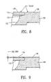
- FIGURE 8 shows details of the cap 110 and the top surface 106 of the implant 100 shown in FIGURES 2-6.
- the forces exerted by the compression springs 120 (FIGURE 3a) keep the cap 110 within the counter-bored hole 112.
- the cap provides a seal to the bone screw hole 102.
- the cap 110 prevents flow of polyethylene and metal from the top surface 106 of the insert 100 through the hole 102.
- the cap 110 also provides a surface upon which the insert 108 (FIGURE 1) can bear during use.
- the cap 110 is manufactured to be relatively thin to provide adequate room for the screw head 114 and the screw head surface 118 as described above with reference to FIGURE 7. However, the cap 110 must be sufficiently thick to withstand the bending loads that are applied to it via compression forces exerted by the insert 108 (FIGURE 1).
- the thickness of the cap 110 and the depth of the counter-bored hole 112 are machined to very close tolerances. At their maximum material condition, the top-facing surface 134 of the cap 110 is exactly flush with the top surface 106 of the tray 100 as shown in FIGURE 8. However, when both the cap 110 and the counter-bored hole 112 are at their least material condition, the top surface 134 of the cap 110 is not flush with the top surface 106 of the tray 100 as shown in FIGURE 9. Rather, a slight step-down of preferably approximately no greater than 002 inches exists between the top surface 106 of the tray 100 and the top surface 134 of the cap 110.
- the top surface 134 of the cap 110 does not interfere with the bottom-facing surface of the polyethylene insert 108 (FIGURE 1). These tolerances also ensure that the cap 110 will not cause premature wear to the insert 108 nor will it interfere with the insertion of the insert 108 in the prosthetic device.
- the cap 110 is preferably manufactured using an Electro-Discharge Machining (EDM) manufacturing process.
- EDM Electro-Discharge Machining
- the caps 110 are easily and inexpensively manufactured within desired tolerances using this well-known manufacturing technique. Several caps can be concurrently machined by stacking sufficiently thin sheets of metal on top of each other.
- the material from which the caps are manufactured is preferably of the same type as the prosthetic implant material. For example, if the implant 100 comprises titanium alloy, the caps 100 are produced from substantially the same titanium alloy. Similarly, if cobalt chromium implants are used, the caps 110 are preferably produced from cobalt chromium.
- the specific materials used for the caps 110 and implants 100 are not crucial, as long as the corrosive effects of in vivo prosthetics are avoided.
- FIGURE 10 shows the inventive cap 110 and the counter-bored hole 112 used with an implant 100 when the implant 100 is secured to the patient's bone using bone cement 140 in addition to, or alternatively, in the place of the plurality of bone screws 104 (FIGURE 2).
- the present invention allows bone cement to intrude into the spherical counter-bored hole 116 as shown in FIGURE 10
- the intrusion of bone cement 140 into the counter-bored hole 116 and the screw hole 102 creates a strong mechanical interlock between the implant and the cement mantle.
- Prior art prosthetic devices require a surgeon to manually prevent the intrusion of the bone cement 140 into the liner cavity.
- the present invention takes advantage of the intrusion of the bone cement 140 into the spherical counter-bored hole 116
- the cap serves as a barrier to the bone cement intruding into the liner cavity.
- FIGURE 11 shows an alternative embodiment of the inventive cap 110 and the counter-bored hole 112 used with an implant 100 when the implant 100 is secured to the patient's bone.
- the present invention contemplates an inventive cap 110 which includes a plurality of protrusions 150 formed into the sidewalls 152 of the cap 110.
- the protrusions 150 are designed to mate with detents or undercuts 154 formed within the sidewalls of the counter-bored hole 112.
Landscapes
- Health & Medical Sciences (AREA)
- Orthopedic Medicine & Surgery (AREA)
- Heart & Thoracic Surgery (AREA)
- Vascular Medicine (AREA)
- Oral & Maxillofacial Surgery (AREA)
- Transplantation (AREA)
- Engineering & Computer Science (AREA)
- Biomedical Technology (AREA)
- Veterinary Medicine (AREA)
- Cardiology (AREA)
- Life Sciences & Earth Sciences (AREA)
- Animal Behavior & Ethology (AREA)
- General Health & Medical Sciences (AREA)
- Public Health (AREA)
- Physical Education & Sports Medicine (AREA)
- Prostheses (AREA)
Abstract
Description
- This invention relates generally to prosthetic implants, and more particularly to such implants which use caps or covers to support the prosthesis and to maintain a physical barrier between the prosthesis and the bone to which the prosthesis is secured.
- Prosthetic implant devices for replacement of damaged or deteriorating portions of bone are well known in the art. There are currently two prevailing means used to secure prosthetic implants to the patient's bone: bone cement or a plurality of bone fixation screws. Both bone cement and fixation screws can be used separately or together to ensure that the implant is secured to the patient's bone. Many commercially available prosthetic implants accommodate both affixation methods. For example, as shown in FIGURE 1, a
tibial tray 100 includes a plurality ofholes 102 which are designed to receive a plurality ofbone screws 104. In practice, a surgeon prepares a patient's bone by first cleaning and then placing bone cement into a properly prepared proximal end of the tibia. The bone cement is preferably applied using a syringe or with digital pressure to obtain intrusion of bone cement into the trabeculae of the patient's tibia. The surgeon typically inserts thestem 103 of thetibial tray 100 into the prepared tibia by hand or by using an impactor or similar tool. After inserting thetibial tray 100 into the prepared tibia, the tibial cement is allowed to harden. The surgeon maintains pressure across thetibial tray 100 while the cement hardens. Supplemental fixation of the tibial tray can also be achieved by screwing the plurality ofbone screws 104 into the patient's tibial bone through the plurality ofholes 102 in thetibial tray 100 with or without cement. Not allholes 102 are necessarily used to receive abone screw 104. - Disadvantageously, the plurality of
bone screw holes 102 in thetibial tray 100 provide passageways for debris to pass from atop surface 106 of the tibial tray through thetibial tray 100. If ahole 102 is not occupied by abone screw 104, and if bone cement is not used, such debris has a higher likelihood of coming into contact with the patient's underlying bone than it does if thehole 102 is occupied by abone screw 104. As is known, unwanted debris or particles of polyethylene or metal may be generated by the articulation of the mating femoral component during use In addition, this unwanted debris can comprise polyethylene particles, or "shavings", or metal debris which result when a polyethylenetibial insert 108 bears, over a period of time, upon thetop surface 106 of thetibial tray 100. Additionally, experience has shown that the polyethylene tibial insert 108 deforms slightly when bearing the weight of a patient over a period of time, causing the polyethylene material on the bottom surface of theinsert 108 to "cold flow" or protrude slighrly into theholes 102 and may also lead to particle wear with time. The unwanted debris has been shown to elieit an osteolytic response in the patient's bone tissue. Disadvantageously, this response can lead to bone resorption and eventual loss of foundation strength within the patient's bone which supports the fixation of theimplant 100. Eventually, theimplant 100 can become loose causing further complications. - In addition, even when
bone screws 104 are inserted in theholes 102, cold flow of the polyethylenetibial insert 108 into the space above the screws can cause problems. As the polyethylene material flows into theholes 102, the thickness of the polyethylenetibial insert 108 is reduced or its shape distorted, increasing the likelihood of premature wear of the prosthetic implant, and thereby reducing the bearing capability of theinsert 108. - Therefore, there is a need for a mechanism which will eliminate the problems associated with the presence of
bone screw holes 102 used in existing prosthetic devices. The present invention provides such a mechanism. - US patent No. 2,401,856 discloses a retaining washer stamped out of steel. However, when installed in an opening, the retaining washer disclosed has openings in its surface thereby not providing a substantially voidless surface.
- An inventive hole cap and associated counter-bored hole for use in protecting and supporting a prosthetic implant are disclosed. The hole cap is preferably sufficiently thick to adequately withstand loading forces produced by a prosthetic insert during use. During surgery, after inserting bone screws into a patient's body, a surgeon quickly and easily inserts the hole cap into an associated counter-bored hole to prevent the flow of unwanted debris into the counter-bored hole and thereafter into the patient's bone underlying the implant. Alternatively, the present hole cap can be used to cover bone screw holes in applications where bone screws are not used and where only bone cement is used to affix the implant to the patient's bone.
- In accordance with one preferred embodiment, the present hole cap includes at least one compression spring. When deflected inwardly toward the center of the hole cap, the compression spring is designed to provide a bias force in an outward direction away from the center of the hole cap. When inserted within the counter-bored hole, the compression spring is deflected by the sidewalls of the counter-bored hole and thereby is compressed outwardly against the surface walls of the hole. During use, the outward compression force of the spring is sufficient to hold the cap in place within the counter-bored hole. The cap thereby provides a block or seal against unwanted flow of metal or plastic debris through the hole and into the patient's bone matter. The cap is easily removed by forcing an instrument through the underside of the hole in an upward direction against the cap.
- In the preferred embodiment, the cap includes a flat-topped disk having a plurality of compression springs formed along the circumference of the disk. The compression springs are formed around the circumference of the cap by forming a plurality of compression spring slots along an inner diameter of the cap. Each compression spring preferably includes a protrusion formed along the tips of the springs. The protrusions are designed to ease the insertion of the caps into the counter-bored hole. The edges or comers of the disk are preferably rounded during manufacture to also ease the insertion and removal of the caps into and out of the counter-bored holes. Once inserted within the hole, the top-facing surface of the cap is substantially flush with the top surface of the implant. The configuration of the present hole cap and counter-bored hole facilitates the intrusion of bone cement into the counter-bored hole which advantageously increases the strength of the mechanical interlock between the implant and the cement mantle. The cap is preferably manufactured using an Electro-Discharge Machining (EDM) manufacturing process.
- Alternative configurations for the inventive hole cap are disclosed These alternative embodiments contemplate the use of various cap retaining means and associated implant holes which are shaped to receive the alternative cap embodiments.
- The details of the preferred embodiment and the alternative embodiments of the present invention are set forth in the accompanying drawings and the description below. Once the details of the invention are known, numerous additional innovations and changes will become obvious to one skilled in the art.
-
- FIGURE 1 is a front perspective exploded view of a tibial tray insert including a plurality of screw holes designed to receive a plurality of bone screws.
- FIGURE 2 is a front perspective exploded view of a tibial tray showing the hole caps and associated counter-bored holes of the present invention.
- FIGURE 3a shows a top plan view of the preferred embodiment of the hole cap of the present invention.
- FIGURE 3b shows a top plan view of a hole cap not representing the invention.
- FIGURE 3c shows a side cross-sectional view of the hole cap shown in FIGURE 3b.
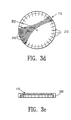
- FIGURE 3d shows a top plan view of a hole cap not representing the invention.
- FIGURE 3e shows a side cross-sectional view of the hole cap shown in FIGURE 3d.
- FIGURE 3f shows a top plan view of an alternative embodiment of the inventive hole cap.
- FIGURE 3g shows a top plan view of a hole cap not representing the invention.
- FIGURE 4 shows a detailed top view of one compression spring of the hole cap of FIGURE 3a.
- FIGURE 5 shows a cross-sectional view of the screw hole and the hole cap of FIGURES 2-4.
- FIGURE 6 shows a side cross-sectional view of the hole cap of FIGURES 2-5 showing the
top-facing surface of the hole cap substantially flush with the top surface of the
implant 100 after insertion of the hole cap within the counter-bored hole. - FIGURE 7 shows the hole cap of FIGURE 6 showing the spacing between the hole cap and the counter-bored hole which allows the bone screw head to rotate with respect to the hole cap.
- FIGURE 8 shows details of the hole cap and the top surface of the implant shown in FIGURES 2-6.
- FIGURE 9 shows the hole cap and counter-bored hole of FIGURE 8 in their least material condition.
- FIGURE 10 shows a side cross-sectional view of the implant, hole cap, and counter-bored hole of FIGURE 5, shown with the implant secured to a patient's bone using bone cement in addition to, or alternatively, in the place of the plurality of bone screws shown in FIGURE 2.
- FIGURE 11 shows a side cross-sectional view of an alternative embodiment of the present hole cap and counter-bored hole.
-
- Like reference numbers and designations in the various drawings refer to like elements.
- Throughout this description, the preferred embodiment and examples shown should be considered as exemplars, rather than as limitations on the present invention.
- FIGURE 2 shows hole caps or covers 110 and associated
counter-bored holes 112 of the present invention. The invention is illustrated throughout the specification as being used in atibial tray 100 and tibial insert prosthetic device. However, thetibial tray 100 andtibial insert 108 is exemplary only, and should not be taken as a limitation of the present invention. For example, theinventive cap 110 andcounter-bored holes 112 can be used with any prosthetic device having holes for the supplemental fixation of the prosthetic device using bone screws. In particular, the present invention may be used with many other prosthetic devices including an acetabular cup, a glenoid component, an ulnar component, a vertebral body, and a bone plate. - Referring again to FIGURE 2, once the
tibial tray 100 is inserted within the patient's bone, the bone screws 104 can be used to affix thetray 100 to the patient's bone. The bone screws 104 may be used with or without bone cement. Once the screws are fully inserted within theholes 102, the head of thescrews 114 are received by sphericalscrew head counter-bores 116 formed into theholes 102. When fully inserted within theholes 102, atop surface 118 in thebone screw head 114 is positioned below thetop surface 106 of thetibial tray 100. With thetibial tray 100 securely attached to the bone, and the bone screws 1.04 fully inserted within the patient's bone, the surgeon prepares the tibial tray for thetibial insert 108 by placing thecaps 110 within thecounter-bored holes 112 formed in theholes 102. As shown in FIGURE 2 and described in more detail hereinbelow with respect to FIGURES 5, 8 and 9, the diameter of thecap 110 and its associatedcounter-bored hole 112 slightly exceeds the diameter of the screw headspherical counter-bore 116. In addition, thecap 110 is manufactured sufficiently thin to provide adequate clearance between the bottom-facing surface of thecap 110 and thetop surface 118 of thescrew head 114. However, thecap 110 is manufactured sufficiently thick to adequately withstand loading forces produced by theinsert 108 on thecap 110. - As described in more detail hereinbelow with reference to FIGURES 5 and 6, a surgeon simply inserts the
cap 110 into its associatedcounter-bored hole 112 after thescrews 104 are fully inserted within the patient's bone. Thecaps 110 include at least onecompression spring 120, each of which compress outwardly against the surface walls of thecounter-bored holes 112. During insertion, the downward force created by the surgeon's placement of acap 110 into acounter-bored hole 112 causes eachspring 120 to deflect in an inward direction toward the center of thecap 110. Once thecaps 110 are fully inserted within theholes 112, the compression springs 120 compress outwardly against the surface walls of thecounter-bored holes 112. The compression force of eachspring 120 holds thecaps 210 in place during use. While inserted within thecounter-bored holes 112, the upwardly facing surface of thecaps 110 are preferably flush with thetop surface 106 of thetibial tray 100. Thus, thecaps 110, in combination with thetop surface 106 of the tibial tray, provide a substantially continuous surface against which thetibial insert 108 bears during use. - The
caps 110 provide a block or a seal which prevents metal and plastic debris from flowing through theholes 102 and becoming lodged within the patient's bone. Thecaps 110 also provide a bearing support to the polyethylene liner or insert which prevents cold flow of polyethylene material which consequently can compromise the strength of theimplant 108. Thecaps 110 are easily pressed into place by the surgeon by simply placing thecap 110 over thehole 102 and pressing the cap within thecounter-bored hole 112. Thecaps 110 are easily removed from a tibial tray 100 (prior to insertion in a patient) by forcing an instrument having a smaller diameter than the diameter of thehole 102 through the underside of thehole 102 in an upward direction against thecup 110. The instrument is pressed against the underside of thecaps 110 with a force that exceeds the compression force produced by the compression springs 120. The compression force exerted by the compression springs 120 is preferably approximately between 2.2 and 4.4 N (0.5 and 1.0 pound-force). Thus, in the preferred embodiment, the compression force is easily overcome by the surgeon and thecaps 110 are thereby easily removed. - FIGURE 3a shows a top view of the
cap 110 of the present invention. As shown in FIGURE 3a, and described above, eachcap 110 preferably comprises a flat-topped disk having at least onecompression spring 120 formed along the perimeter of thecap 110. The diameter "D" 122 of thecap 110 is manufactured to be slightly smaller than the diameter of the counter-bored hole 112 (FIGURE 2) into which thecap 110 is inserted during use. The difference in diameters between thediameter D 122 and the diameter of thehole 112 preferably ranges between 0.0127 to 0.0635mm (-0.0005 to 0.0025 inches). Thecaps 110 are manufactured so that thediameter d 124 is always greater than thediameter D 122. This ensures that the sidewalls of thecounter-bored holes 112 first contact the compression springs 120 when thecap 110 is first inserted within theholes 102. The maximum ratio of D/d is preferably approximately 0.995. The ratio of thediameter d 124 over the diameter of thecounter-bore hole 112 ranges between approximately 1.009 (max) to 1.001 (min). - As shown in FIGURE 3a, the
preferred cap 110 includes a plurality of compression springs 120 formed along its circumference. Although FIGURE 3a shows thecap 110 having four compression springs 120, one or more compression springs may be used. The compression springs 120 are formed around the circumference of thecap 110 by forming a plurality ofcompression spring slots 126 as shown in FIGURE 3a. Theslots 126 provide an area into which the compression springs 120 are deflected when thecap 110 is fully inserted within thecounter-bored hole 112 of the tibial tray 100 (FIGURE 2). Although the preferred embodiment of the hole cap is shown in FIGURE 3a, a number of alternative embodiments are contemplated. For example, an alternative embodiment of theinventive hole cap 110 is shown in FIGURES 3f. - FIGURE 3f shows a top plan view of an alternative embodiment of the
inventive cap 110. Similar to the embodiment shown in FIGURE 3a, the embodiment shown in FIGURE 3f includes compression springs 120 formed along the outer circumference of thecap 110. The compression springs 120 are formed into thecap 110 by forming a plurality ofcompression spring slots 126 into the cap as shown in FIGURE 3f. Theslots 126 and springs 120 shown in FIGURE 3f are elongated relative to those shown in FIGURE 3a. As described above with reference to the preferred embodiment shown in FIGURE 3a, the compression springs 120 flex in an inward direction when inserted within an associated counter-bored hole. Thesprings 120 exert a sufficient force away from thecenter 202 of thecap 110 and against the sidewalls of thehole 112 to prevent the cap from inadvertently disengaging from thehole 112 during use. - FIGURE 4 shows a detailed top view of one
compression spring 120 shown in FIGURE 3a. The compression springs 120 preferably include aprotrusion 128 formed along tips of thesprings 120. As shown in FIGURE 4, the diameter of thecap 110, when measured from the outer periphery of theprotrusion 128, is slightly larger than the diameter of thecap 110 when measured from the outer periphery of the remainder of thespring 120. That is, theprotrusion 128 extends a distance slightly beyond the rest of the perimeter of thehole cap 110. The distance that theprotrusion 128 extends beyond the perimeter of the hole cap is preferably approximately between 0.0254 to 0.0254mm (0.001 to 0.010 in). - FIGURE 5 shows a cross-sectional view of the
hole 102 and theinventive cap 110 of FIGURES 2-4. Thebone screw hole 102 preferably includes acounter-bored hole 112 configured to receive thecap 110 when thecap 110 is inserted within thecounter-bored hole 112. As shown in FIGURE 5, the diameter of thecap 110 and thecounter-bored hole 112 slightly exceeds the diameter of thespherical counter-bore 116. The cap protrusions 128 (FIGURE 4) extend slightly beyond the diameter of thecounter-bored hole 112. In one preferred embodiment, an insertion ramp or aninclined surface 130 is milled around the top-facing surface of thecounter-bored hole 112 and inclined in a direction toward the center of thecounter-bored hole 112 as shown in FIGURE 5. Theinclined surface 130 of thecounter-bored hole 112 has a diameter which is slightly larger than the diameter of thecounter-bored hole 112. Theinclined surface 130 allows thecap 110 to be easily centered within thecounter-bored hole 112 and allows the surgeon to insert the cap within thehole 112. - During manufacture, the
inventive cap 110 preferably is removed of all burrs during manufacture and is turnble-polished so that all of the edges of thecap 110 have a slightly curved corner radius. For example, thecorners 132 of thecap 110 shown in FIGURE 5 are slightly curved so that they have no sharp edges. Thecurved corners 132 of thecap 110 serve to aid assembly of thecap 110 into thecounter-bored hole 112. Thecap 110 is preferably inserted by a surgeon into thecounter-bored hole 112 by placing thecap 110 over thehole 102 and pressing the cap against theinclined surface 130 in a downward direction toward thescrew hole 102. Thecap 110 may be assembled having either side facing upward, and is also rotationally independent. That is the rotation of thecap 110 within thecounter-bored hole 112 is unimportant to the operation of the implant. - During insertion, the downward force applied by the surgeon upon a top-facing
surface 134 of thecap 110 causes the compression springs 120 to compress and deflect in an inward direction into anarea 123 defined by the slots 126 (FIGURE 3a). Some slight resistanec is initially exerted by the compression springs 120 because theprotrusions 128 and the compression springs 120 have a slightly greater diameter than the diameter of thecounter-bored hole 112. The resistance exerted by the compression springs 120 is easily overcome due to theinclined surfaces 130 and thecurved corners 132 of thecap 110. Once the surgeon overcomes the resistance exerted by the compression springs 120, the cap is pushed downward into thecounter-bored hole 112. Thus, thecaps 110 are self-centering within thecounter-bored hole 112 once the surgeon places the cap over thehole 102 as shown in FIGURE 5. - Once inserted within the
counter-bored hole 112, the top-facingsurface 134 of thecap 110 is substantially flush with thetop surface 106 of theimplant 100 as shown in FIGURE 6. A bottom-facingsurface 136 of thecap 110 is kept a short distance away from thetop surface 118 of thescrew head 114 when thescrew 104 is completely inserted within the patient's bone. When fully inserted within thecounter-bored hole 112, thebottom surface 136 of thecap 110 and thetop surface 118 of thescrew head 114 define avolume 138 within which thetop surface 118 of thescrew head 114 can be angled or rotated. For example, as shown in FIGURE 7, the spacing between thepresent hole cap 110 and thecounter-bored hole 112 provides adequate room in thearea 138 into which thebone screw head 114 can be angled or rotated. This feature is particularly advantageous because a surgeon often needs to tilt thescrew 104 to reach good bone purchase. - The compression springs 120 exert a sufficient force away from the center of the
cap 110 and against the sidewalls of thecounter-bored hole 112 to prevent thecap 110 from inadvertently disengaging from thecounter-bored hole 112 during use. Thesprings 120 preferably exert a compression force which falls within the elastic range of the counter-bored hole material (i.e., below the yield strength). The compression springs also preferably remain in their elastic range during insertion. That is, the force exerted by thesprings 120 also falls below the yield strength of the compression springs 120. Thus, neither thesprings 120, nor the sidewalls of thecounter-bored hole 112, are permanently deformed during insertion and removal of thecap 110. The spring slots 126 (FIGURE 3a) are designed to provide adequate room for the plurality ofsprings 120 to deflect into when thecap 110 is fully inserted within thecounter-bored hole 112. However, thedeflection area 123 formed by theslots 126 is dimensioned to be less than thewidth 133 of the base of thecounter-bored hole 112. This ensures that unwanted debris does not pass through theslot 126 into thehole 102. - FIGURE 8 shows details of the
cap 110 and thetop surface 106 of theimplant 100 shown in FIGURES 2-6. As shown in FIGURE 8, when thecap 110 is fully inserted within thecounter-bored hole 112, the forces exerted by the compression springs 120 (FIGURE 3a) keep thecap 110 within thecounter-bored hole 112. The cap provides a seal to thebone screw hole 102. When fully inserted within thecounter-bored hole 112, thecap 110 prevents flow of polyethylene and metal from thetop surface 106 of theinsert 100 through thehole 102. Thecap 110 also provides a surface upon which the insert 108 (FIGURE 1) can bear during use. Thecap 110 is manufactured to be relatively thin to provide adequate room for thescrew head 114 and thescrew head surface 118 as described above with reference to FIGURE 7. However, thecap 110 must be sufficiently thick to withstand the bending loads that are applied to it via compression forces exerted by the insert 108 (FIGURE 1). - The thickness of the
cap 110 and the depth of thecounter-bored hole 112 are machined to very close tolerances. At their maximum material condition, the top-facingsurface 134 of thecap 110 is exactly flush with thetop surface 106 of thetray 100 as shown in FIGURE 8. However, when both thecap 110 and thecounter-bored hole 112 are at their least material condition, thetop surface 134 of thecap 110 is not flush with thetop surface 106 of thetray 100 as shown in FIGURE 9. Rather, a slight step-down of preferably approximately no greater than 002 inches exists between thetop surface 106 of thetray 100 and thetop surface 134 of thecap 110. By manufacturing thecap 110 and thecounter-bored hole 112 to these tolerances, thetop surface 134 of thecap 110 does not interfere with the bottom-facing surface of the polyethylene insert 108 (FIGURE 1). These tolerances also ensure that thecap 110 will not cause premature wear to theinsert 108 nor will it interfere with the insertion of theinsert 108 in the prosthetic device. - The
cap 110 is preferably manufactured using an Electro-Discharge Machining (EDM) manufacturing process. Thecaps 110 are easily and inexpensively manufactured within desired tolerances using this well-known manufacturing technique. Several caps can be concurrently machined by stacking sufficiently thin sheets of metal on top of each other. The material from which the caps are manufactured is preferably of the same type as the prosthetic implant material. For example, if theimplant 100 comprises titanium alloy, thecaps 100 are produced from substantially the same titanium alloy. Similarly, if cobalt chromium implants are used, thecaps 110 are preferably produced from cobalt chromium. The specific materials used for thecaps 110 andimplants 100 are not crucial, as long as the corrosive effects of in vivo prosthetics are avoided. - FIGURE 10 shows the
inventive cap 110 and thecounter-bored hole 112 used with animplant 100 when theimplant 100 is secured to the patient's bone usingbone cement 140 in addition to, or alternatively, in the place of the plurality of bone screws 104 (FIGURE 2). The present invention allows bone cement to intrude into the sphericalcounter-bored hole 116 as shown in FIGURE 10 The intrusion ofbone cement 140 into thecounter-bored hole 116 and thescrew hole 102 creates a strong mechanical interlock between the implant and the cement mantle. Prior art prosthetic devices require a surgeon to manually prevent the intrusion of thebone cement 140 into the liner cavity. Preventing intrusion of the bone cement is a time-consuming process and thus increases operating-room time and thereby increases the costs and morbidity associated with prosthetic surgery. In addition, bone cement particles often become loose within the patient's joint, leading to foreign body abrasive wear which in turn leads to premature insert wear. As shown in FIGURE 10, the present invention takes advantage of the intrusion of thebone cement 140 into the sphericalcounter-bored hole 116 The cap serves as a barrier to the bone cement intruding into the liner cavity. - A number of embodiments of the present invention have been described. Nevertheless, it will be understood that various modifications may be made without departing from the scope of the invention. For example, FIGURE 11 shows an alternative embodiment of the
inventive cap 110 and thecounter-bored hole 112 used with animplant 100 when theimplant 100 is secured to the patient's bone. As shown in FIGURE 11, the present invention contemplates aninventive cap 110 which includes a plurality ofprotrusions 150 formed into thesidewalls 152 of thecap 110. As shown in FIGURE 11, theprotrusions 150 are designed to mate with detents or undercuts 154 formed within the sidewalls of thecounter-bored hole 112. Thus, when thecap 110 is inserted within thecounter-bored hole 112, theprotrusions 150 interlock with thedetents 154 formed within thehole 112. Thecap 110 is thereby secured in place within thehole 112. Accordingly, it is to be understood that the invention is not to be limited by the specific illustrated embodiment, but only by the scope of the appended claims.
Claims (16)
- A hole cap adapted to be received in an opening provided in a prosthetic device to seal the opening when the hole cap (110) is received therein, the hole cap (110) characterized by comprising:a substantially flat and essentially voidless disk; andat least one compression spring (120) that, when the hole cap (110) is in an uncompressed state, is separated from the disk by a slot which defines an open area, wherein the hole cap is sized and dimensioned for receipt by the opening formed in the prosthetic implant, wherein the at least one compression spring is compressed into the open area defined by the slot to render the hole cap essentially voidless when the hole cap is received in the opening in the prosthetic implant.
- The hole cap of claim 1, wherein the hole cap (110) is substantially round.
- The hole cap of claim 1, wherein the spring is deflected when the cap (110) is inserted into the counter-bored hole (112).
- The hole cap of claim 1, wherein the at least one compression spring (120) includes a protrusion which extends the spring slightly beyond the diameter of the disk.
- The hole cap of claim 1, wherein the disk comprises titanium alloy.
- The hole cap of claim 1, wherein the disk comprises cobalt chromium alloy.
- The hole cap of claim 1, wherein the counter-bored hole (112) includes a cap insertion ramp, and wherein the insertion ramp has an inclined surface (130) which assists insertion of the cap into the hole.
- The hole cap to claim 1 installed in a cap retaining hole in an arrangement that seals a screwhole of a prosthetic implant wherein the cap retaining hole is formed in a side wall (200) of the screw hole, wherein the cap retaining hole is shaped to recieve the hole cap, and wherein at least one the compression spring exerts forces against the sidewall of the cap retaining hole sufficient to prevent inadvertant removal of the hole cap from the cap retaining hole, the hole cap forming a substanitally voidless surface over the cap retaining hole.
- The hole cap of claim 8, wherein the screw hole (102) includes a top portion which is shaped to receive a screw head of a bone screw, and wherein the hole cap (110) does not interfere with a tilting of the screw head when the cap is fully inserted within the cap retaining hole.
- The hole cap of claim 8, wherein at least one the compression springs include protrusions which extend slightly beyond the outer diameter of the hole cap (110), and wherein the protrusions contact the sidewalls of the cap retaining hole when the cap is inserted within the retaining hole.
- The hole cap of claim 8, wherein the hole cap (110) includes a plurality of rounded edges.
- The hole cap of claim 8, wherein the cap retaining hole includes a cap insertion ramp, and wherein the insertion ramp has an inclined surface which assists insertion of the cap into the hole.
- The hole cap of claim 8, wherein the hole cap (110) includes at least one protrusion formed along the perimeter of the cap, and wherein the cap retaining hole includes at least one detent formed into the side wall of the screw hole (102), and wherein the at least one protrusion interlocks with the at least one detent when the hole cap is inserted into the hole.
- The hole cap of claim 1, wherein at least one the compression spring is comprised of mating tines extending from an outer perimeter of the disk, and wherein the mating tines are shaped to be received by an insertion slot formed into the cap retaining hole, such that where the hole cap is inserted in the prosthetic device, it forms a substantially voidless surface along the prosthetic implant over the cap retaining hole.
- The hole cap of claim 1, wherein the hole cap (110) is adapted to be received in a counter-bored hole (112) in the opening of the prosthetic device.
- The hole cap of claim 8, wherein the screw hole (102) is provided with a counter-bored hole (112) in the opening of the screw hole (102).
Applications Claiming Priority (3)
| Application Number | Priority Date | Filing Date | Title |
|---|---|---|---|
| US35785594A | 1994-12-16 | 1994-12-16 | |
| US357855 | 1994-12-16 | ||
| PCT/US1995/016111 WO1996018362A1 (en) | 1994-12-16 | 1995-12-13 | Hole caps for prosthetic implants |
Publications (3)
| Publication Number | Publication Date |
|---|---|
| EP0847257A1 EP0847257A1 (en) | 1998-06-17 |
| EP0847257A4 EP0847257A4 (en) | 1999-10-13 |
| EP0847257B1 true EP0847257B1 (en) | 2003-07-09 |
Family
ID=23407316
Family Applications (1)
| Application Number | Title | Priority Date | Filing Date |
|---|---|---|---|
| EP95943068A Expired - Lifetime EP0847257B1 (en) | 1994-12-16 | 1995-12-13 | Hole caps for prosthetic implants |
Country Status (6)
| Country | Link |
|---|---|
| US (1) | US5725580A (en) |
| EP (1) | EP0847257B1 (en) |
| JP (1) | JPH10510735A (en) |
| DE (1) | DE69531259T2 (en) |
| ES (1) | ES2202383T3 (en) |
| WO (1) | WO1996018362A1 (en) |
Families Citing this family (41)
| Publication number | Priority date | Publication date | Assignee | Title |
|---|---|---|---|---|
| US5925077A (en) * | 1997-04-02 | 1999-07-20 | Biomet, Inc. | Apparatus and method for plugging holes in an acetabular shell component |
| US6585770B1 (en) * | 1997-06-02 | 2003-07-01 | Sdgi Holdings, Inc. | Devices for supporting bony structures |
| US6120541A (en) * | 1999-03-23 | 2000-09-19 | Johnson; Lanny L. | Apparatus for use in grafting articular cartilage |
| DE10029637C2 (en) * | 2000-06-17 | 2002-04-11 | Biomet Merck Deutschland Gmbh | endoprosthesis |
| US6413259B1 (en) | 2000-12-14 | 2002-07-02 | Blackstone Medical, Inc | Bone plate assembly including a screw retaining member |
| US6485519B2 (en) | 2001-01-29 | 2002-11-26 | Bristol-Myers Squibb Company | Constrained prosthetic knee with rotating bearing |
| US6719800B2 (en) | 2001-01-29 | 2004-04-13 | Zimmer Technology, Inc. | Constrained prosthetic knee with rotating bearing |
| US6783547B2 (en) | 2002-04-05 | 2004-08-31 | Howmedica Corp. | Apparatus for fusing adjacent bone structures |
| US7001389B1 (en) | 2002-07-05 | 2006-02-21 | Navarro Richard R | Fixed and variable locking fixation assembly |
| US7524325B2 (en) * | 2002-11-04 | 2009-04-28 | Farid Bruce Khalili | Fastener retention system |
| WO2004089245A2 (en) * | 2003-04-04 | 2004-10-21 | Theken Surgical, Llc | Bone anchor |
| US20040220679A1 (en) * | 2003-05-01 | 2004-11-04 | Diaz Robert L. | Hybrid ceramic composite implants |
| FR2869216B1 (en) * | 2004-04-26 | 2006-11-17 | Fournitures Hospitalieres Ind | SYSTEM FOR FASTENING A TIBIAL PLATE FOR KNEE PROSTHESIS |
| US20070173934A1 (en) * | 2006-01-20 | 2007-07-26 | Sdgi Holdings, Inc. | Devices to protect features on an implant and methods of use |
| US8560047B2 (en) | 2006-06-16 | 2013-10-15 | Board Of Regents Of The University Of Nebraska | Method and apparatus for computer aided surgery |
| US8632600B2 (en) | 2007-09-25 | 2014-01-21 | Depuy (Ireland) | Prosthesis with modular extensions |
| US7988736B2 (en) * | 2008-02-27 | 2011-08-02 | Biomet Manufacturing Corp. | Method and apparatus for providing resorbable fixation of press-fit implants |
| FR2928828B1 (en) * | 2008-03-21 | 2010-04-02 | Tornier Sa | CARTILAGE RESURFACING IMPLANT |
| US8123815B2 (en) * | 2008-11-24 | 2012-02-28 | Biomet Manufacturing Corp. | Multiple bearing acetabular prosthesis |
| US8454707B2 (en) * | 2009-04-03 | 2013-06-04 | University Of Maryland | Biomedical implantable material and methods of producing the same |
| US8308810B2 (en) | 2009-07-14 | 2012-11-13 | Biomet Manufacturing Corp. | Multiple bearing acetabular prosthesis |
| US11484627B2 (en) | 2010-10-20 | 2022-11-01 | 206 Ortho, Inc. | Method and apparatus for treating bone fractures, and/or for fortifying and/or augmenting bone, including the provision and use of composite implants, and novel composite structures which may be used for medical and non-medical applications |
| US9320601B2 (en) | 2011-10-20 | 2016-04-26 | 206 Ortho, Inc. | Method and apparatus for treating bone fractures, and/or for fortifying and/or augmenting bone, including the provision and use of composite implants |
| US11207109B2 (en) | 2010-10-20 | 2021-12-28 | 206 Ortho, Inc. | Method and apparatus for treating bone fractures, and/or for fortifying and/or augmenting bone, including the provision and use of composite implants, and novel composite structures which may be used for medical and non-medical applications |
| US11291483B2 (en) | 2010-10-20 | 2022-04-05 | 206 Ortho, Inc. | Method and apparatus for treating bone fractures, and/or for fortifying and/or augmenting bone, including the provision and use of composite implants |
| US11058796B2 (en) | 2010-10-20 | 2021-07-13 | 206 Ortho, Inc. | Method and apparatus for treating bone fractures, and/or for fortifying and/or augmenting bone, including the provision and use of composite implants, and novel composite structures which may be used for medical and non-medical applications |
| US10525168B2 (en) * | 2010-10-20 | 2020-01-07 | 206 Ortho, Inc. | Method and apparatus for treating bone fractures, and/or for fortifying and/or augmenting bone, including the provision and use of composite implants, and novel composite structures which may be used for medical and non-medical applications |
| US10525169B2 (en) | 2010-10-20 | 2020-01-07 | 206 Ortho, Inc. | Method and apparatus for treating bone fractures, and/or for fortifying and/or augmenting bone, including the provision and use of composite implants, and novel composite structures which may be used for medical and non-medical applications |
| EP2629780A4 (en) | 2010-10-20 | 2014-10-01 | 206 Ortho Inc | Implantable polymer for bone and vascular lesions |
| US20120109111A1 (en) * | 2010-10-29 | 2012-05-03 | Empire Technology Development Llc | Fenestration system |
| US9498231B2 (en) | 2011-06-27 | 2016-11-22 | Board Of Regents Of The University Of Nebraska | On-board tool tracking system and methods of computer assisted surgery |
| US11911117B2 (en) | 2011-06-27 | 2024-02-27 | Board Of Regents Of The University Of Nebraska | On-board tool tracking system and methods of computer assisted surgery |
| WO2013052187A2 (en) | 2011-06-27 | 2013-04-11 | Board Of Regents Of The University Of Nebraska | On-board tool tracking system and methods of computer assisted surgery |
| US8882851B2 (en) * | 2011-09-20 | 2014-11-11 | Larry Nelson Smith | Implantable prosthetic device for distribution of weight on amputated limb and method of use with an external prosthetic device |
| US8932367B2 (en) | 2013-02-13 | 2015-01-13 | Larry N. Smith | Shock absorbing implantable limb prosthetic |
| US9237953B2 (en) * | 2013-03-15 | 2016-01-19 | Depuy (Ireland) | Mechanical assembly of pegs to prosthesis |
| US10105149B2 (en) | 2013-03-15 | 2018-10-23 | Board Of Regents Of The University Of Nebraska | On-board tool tracking system and methods of computer assisted surgery |
| JP2016525379A (en) | 2013-05-23 | 2016-08-25 | 206 オーソ,インコーポレーテッド | Methods and apparatus for treating fractures and / or for reinforcing and / or augmenting bone, including the provision and use of composite implants |
| DE102013213831B4 (en) * | 2013-07-15 | 2015-01-29 | Heraeus Medical Gmbh | Knee spacer for temporary replacement of an artificial knee joint |
| CN104887355B (en) * | 2015-05-08 | 2017-05-03 | 江苏奥康尼医疗科技发展有限公司 | Artificial knee joint tibial tray |
| CN111248990B (en) * | 2020-02-11 | 2022-08-05 | 云阳县江口镇中心卫生院(云阳县第二人民医院) | Proximal tibia end fixing device for knee joint replacement surgery |
Family Cites Families (15)
| Publication number | Priority date | Publication date | Assignee | Title |
|---|---|---|---|---|
| US1765239A (en) * | 1928-12-22 | 1930-06-17 | Viscose Co | Retaining ring for spinning-box lids |
| GB566073A (en) * | 1943-05-06 | 1944-12-12 | Automotive Prod Co Ltd | Improved locating means for retaining washers and the like |
| US3023925A (en) * | 1959-09-21 | 1962-03-06 | Fred D Sher | Container for packaging merchandise |
| US4320421A (en) * | 1980-05-27 | 1982-03-16 | International Business Machines Corporation | Rotary actuator for file protect function |
| US4566138A (en) * | 1983-03-08 | 1986-01-28 | Zimmer, Inc. | Prosthetic device with spacers |
| US4536897B1 (en) * | 1983-07-08 | 1995-11-21 | Robert M Powell | Intraocular lens |
| CH670381A5 (en) * | 1986-05-05 | 1989-06-15 | Sulzer Ag | |
| US4795468A (en) * | 1987-12-23 | 1989-01-03 | Zimmer, Inc. | Mechanism and method for locking a bearing insert to the base of a prosthetic implant |
| US4955325A (en) * | 1989-06-14 | 1990-09-11 | Osteonics Corp. | Acetabular cup component cement spacer system |
| US4973844A (en) * | 1989-07-10 | 1990-11-27 | Donnelly Corporation | Vehicular moisture sensor and mounting apparatus therefor |
| WO1991003994A1 (en) * | 1989-09-21 | 1991-04-04 | Krasnodarsky Kraevoi Sovet Vsesojuznogo Obschestva Izobretatelei I Ratsionalizatorov | Device for fitting a prosthesis for an extremity |
| FR2651996B3 (en) * | 1989-09-21 | 1991-08-09 | Augoyard Marc | CEMENTED PROSTHESIS CUP. |
| EP0434604A1 (en) * | 1989-12-15 | 1991-06-26 | GebràDer Sulzer Aktiengesellschaft | Anchored shaft for a femoral prosthesis |
| US5435455A (en) * | 1989-12-22 | 1995-07-25 | Volkswagon Ag | Locking device |
| US5226917A (en) * | 1991-02-14 | 1993-07-13 | Smith & Nephew Richards Inc. | Acetabular prosthesis with anchoring pegs |
-
1995
- 1995-12-13 EP EP95943068A patent/EP0847257B1/en not_active Expired - Lifetime
- 1995-12-13 JP JP8519220A patent/JPH10510735A/en active Pending
- 1995-12-13 ES ES95943068T patent/ES2202383T3/en not_active Expired - Lifetime
- 1995-12-13 WO PCT/US1995/016111 patent/WO1996018362A1/en not_active Ceased
- 1995-12-13 DE DE69531259T patent/DE69531259T2/en not_active Expired - Lifetime
-
1996
- 1996-07-11 US US08/680,276 patent/US5725580A/en not_active Expired - Lifetime
Also Published As
| Publication number | Publication date |
|---|---|
| DE69531259T2 (en) | 2004-05-19 |
| EP0847257A4 (en) | 1999-10-13 |
| WO1996018362A1 (en) | 1996-06-20 |
| JPH10510735A (en) | 1998-10-20 |
| EP0847257A1 (en) | 1998-06-17 |
| US5725580A (en) | 1998-03-10 |
| ES2202383T3 (en) | 2004-04-01 |
| DE69531259D1 (en) | 2003-08-14 |
Similar Documents
| Publication | Publication Date | Title |
|---|---|---|
| US5725580A (en) | Hole caps for prosthetic implants | |
| US5702461A (en) | Prosthesis fixturing device | |
| AU695430B2 (en) | Cup | |
| US5080677A (en) | Acetabular component of hip joint prosthesis | |
| EP0941718B1 (en) | Acetabular prosthesis with ring lock mechanism | |
| US9445903B2 (en) | Multi-bearing acetabular prosthesis | |
| US6569202B2 (en) | Tray and liner for joint replacement system | |
| US5782929A (en) | Acetabular shell having sintered screw hole plugs | |
| US7371261B2 (en) | Acetabular component of total hip replacement assembly | |
| US5443520A (en) | Cementless fixation element for an artificial hip joint with rotating cover element | |
| CA2842421C (en) | Lined femoral cup | |
| JP2010515478A (en) | Artificial acetabulum with a sterile contact surface | |
| US20080208350A1 (en) | Acetabular component of total hip replacement assembly | |
| US20040225369A1 (en) | Method and apparatus for use of a metal-metal constrained liner | |
| US8128705B2 (en) | Assembly for use in implantation of a joint component | |
| US5935174A (en) | Acetabular shell having flexible dome hole diaphragm | |
| US20090171464A1 (en) | Joint socket for a hip endoprosthesis | |
| JPS61217159A (en) | Artificial acetabulum equipped with holder and acetabulum insert | |
| EP0701420B1 (en) | Acetabular shell having screw holes with breakout seals | |
| EP1395206B1 (en) | Acetabular cup for hip joint prosthesis | |
| RU2240757C1 (en) | Endoprosthesis of hip joint cotyloid cavity | |
| AU702143B2 (en) | Prosthesis fixturing device | |
| CA2430306C (en) | Prosthesis fixturing device | |
| EP1441673B1 (en) | Method of production of an artificial joint prosthesis with closing element | |
| JP2581551Y2 (en) | Acetabular socket in artificial hip joint |
Legal Events
| Date | Code | Title | Description |
|---|---|---|---|
| PUAI | Public reference made under article 153(3) epc to a published international application that has entered the european phase |
Free format text: ORIGINAL CODE: 0009012 |
|
| 17P | Request for examination filed |
Effective date: 19970711 |
|
| AK | Designated contracting states |
Kind code of ref document: A1 Designated state(s): DE ES FR GB IT |
|
| A4 | Supplementary search report drawn up and despatched |
Effective date: 19990826 |
|
| AK | Designated contracting states |
Kind code of ref document: A4 Designated state(s): DE ES FR GB IT |
|
| RIC1 | Information provided on ipc code assigned before grant |
Free format text: 6A 61F 2/28 A, 6A 61F 2/38 B |
|
| 17Q | First examination report despatched |
Effective date: 20020218 |
|
| GRAH | Despatch of communication of intention to grant a patent |
Free format text: ORIGINAL CODE: EPIDOS IGRA |
|
| GRAH | Despatch of communication of intention to grant a patent |
Free format text: ORIGINAL CODE: EPIDOS IGRA |
|
| GRAA | (expected) grant |
Free format text: ORIGINAL CODE: 0009210 |
|
| AK | Designated contracting states |
Designated state(s): DE ES FR GB IT |
|
| REG | Reference to a national code |
Ref country code: GB Ref legal event code: FG4D |
|
| REF | Corresponds to: |
Ref document number: 69531259 Country of ref document: DE Date of ref document: 20030814 Kind code of ref document: P |
|
| REG | Reference to a national code |
Ref country code: ES Ref legal event code: FG2A Ref document number: 2202383 Country of ref document: ES Kind code of ref document: T3 |
|
| PLBE | No opposition filed within time limit |
Free format text: ORIGINAL CODE: 0009261 |
|
| STAA | Information on the status of an ep patent application or granted ep patent |
Free format text: STATUS: NO OPPOSITION FILED WITHIN TIME LIMIT |
|
| ET | Fr: translation filed | ||
| 26N | No opposition filed |
Effective date: 20040414 |
|
| PGFP | Annual fee paid to national office [announced via postgrant information from national office to epo] |
Ref country code: IT Payment date: 20101218 Year of fee payment: 16 Ref country code: GB Payment date: 20101208 Year of fee payment: 16 |
|
| PGFP | Annual fee paid to national office [announced via postgrant information from national office to epo] |
Ref country code: DE Payment date: 20101208 Year of fee payment: 16 |
|
| PGFP | Annual fee paid to national office [announced via postgrant information from national office to epo] |
Ref country code: FR Payment date: 20111219 Year of fee payment: 17 |
|
| PGFP | Annual fee paid to national office [announced via postgrant information from national office to epo] |
Ref country code: ES Payment date: 20120116 Year of fee payment: 17 |
|
| GBPC | Gb: european patent ceased through non-payment of renewal fee |
Effective date: 20121213 |
|
| REG | Reference to a national code |
Ref country code: FR Ref legal event code: ST Effective date: 20130830 |
|
| REG | Reference to a national code |
Ref country code: DE Ref legal event code: R119 Ref document number: 69531259 Country of ref document: DE Effective date: 20130702 |
|
| PG25 | Lapsed in a contracting state [announced via postgrant information from national office to epo] |
Ref country code: DE Free format text: LAPSE BECAUSE OF NON-PAYMENT OF DUE FEES Effective date: 20130702 |
|
| PG25 | Lapsed in a contracting state [announced via postgrant information from national office to epo] |
Ref country code: FR Free format text: LAPSE BECAUSE OF NON-PAYMENT OF DUE FEES Effective date: 20130102 Ref country code: GB Free format text: LAPSE BECAUSE OF NON-PAYMENT OF DUE FEES Effective date: 20121213 |
|
| PG25 | Lapsed in a contracting state [announced via postgrant information from national office to epo] |
Ref country code: IT Free format text: LAPSE BECAUSE OF NON-PAYMENT OF DUE FEES Effective date: 20121213 |
|
| REG | Reference to a national code |
Ref country code: ES Ref legal event code: FD2A Effective date: 20140307 |
|
| PG25 | Lapsed in a contracting state [announced via postgrant information from national office to epo] |
Ref country code: ES Free format text: LAPSE BECAUSE OF NON-PAYMENT OF DUE FEES Effective date: 20121214 |