EP0846839B1 - Method and apparatus for placing and cementing casing in horizontal wells - Google Patents
Method and apparatus for placing and cementing casing in horizontal wells Download PDFInfo
- Publication number
- EP0846839B1 EP0846839B1 EP97309000A EP97309000A EP0846839B1 EP 0846839 B1 EP0846839 B1 EP 0846839B1 EP 97309000 A EP97309000 A EP 97309000A EP 97309000 A EP97309000 A EP 97309000A EP 0846839 B1 EP0846839 B1 EP 0846839B1
- Authority
- EP
- European Patent Office
- Prior art keywords
- casing
- string
- baffle assembly
- collet
- fluid pressure
- Prior art date
- Legal status (The legal status is an assumption and is not a legal conclusion. Google has not performed a legal analysis and makes no representation as to the accuracy of the status listed.)
- Expired - Lifetime
Links
Images




Classifications
-
- E—FIXED CONSTRUCTIONS
- E21—EARTH OR ROCK DRILLING; MINING
- E21B—EARTH OR ROCK DRILLING; OBTAINING OIL, GAS, WATER, SOLUBLE OR MELTABLE MATERIALS OR A SLURRY OF MINERALS FROM WELLS
- E21B23/00—Apparatus for displacing, setting, locking, releasing or removing tools, packers or the like in boreholes or wells
-
- E—FIXED CONSTRUCTIONS
- E21—EARTH OR ROCK DRILLING; MINING
- E21B—EARTH OR ROCK DRILLING; OBTAINING OIL, GAS, WATER, SOLUBLE OR MELTABLE MATERIALS OR A SLURRY OF MINERALS FROM WELLS
- E21B21/00—Methods or apparatus for flushing boreholes, e.g. by use of exhaust air from motor
- E21B21/10—Valve arrangements in drilling-fluid circulation systems
-
- E—FIXED CONSTRUCTIONS
- E21—EARTH OR ROCK DRILLING; MINING
- E21B—EARTH OR ROCK DRILLING; OBTAINING OIL, GAS, WATER, SOLUBLE OR MELTABLE MATERIALS OR A SLURRY OF MINERALS FROM WELLS
- E21B23/00—Apparatus for displacing, setting, locking, releasing or removing tools, packers or the like in boreholes or wells
- E21B23/04—Apparatus for displacing, setting, locking, releasing or removing tools, packers or the like in boreholes or wells operated by fluid means, e.g. actuated by explosion
-
- E—FIXED CONSTRUCTIONS
- E21—EARTH OR ROCK DRILLING; MINING
- E21B—EARTH OR ROCK DRILLING; OBTAINING OIL, GAS, WATER, SOLUBLE OR MELTABLE MATERIALS OR A SLURRY OF MINERALS FROM WELLS
- E21B33/00—Sealing or packing boreholes or wells
- E21B33/10—Sealing or packing boreholes or wells in the borehole
- E21B33/13—Methods or devices for cementing, for plugging holes, crevices or the like
- E21B33/14—Methods or devices for cementing, for plugging holes, crevices or the like for cementing casings into boreholes
- E21B33/16—Methods or devices for cementing, for plugging holes, crevices or the like for cementing casings into boreholes using plugs for isolating cement charge; Plugs therefor
-
- E—FIXED CONSTRUCTIONS
- E21—EARTH OR ROCK DRILLING; MINING
- E21B—EARTH OR ROCK DRILLING; OBTAINING OIL, GAS, WATER, SOLUBLE OR MELTABLE MATERIALS OR A SLURRY OF MINERALS FROM WELLS
- E21B33/00—Sealing or packing boreholes or wells
- E21B33/10—Sealing or packing boreholes or wells in the borehole
- E21B33/13—Methods or devices for cementing, for plugging holes, crevices or the like
- E21B33/14—Methods or devices for cementing, for plugging holes, crevices or the like for cementing casings into boreholes
- E21B33/16—Methods or devices for cementing, for plugging holes, crevices or the like for cementing casings into boreholes using plugs for isolating cement charge; Plugs therefor
- E21B33/167—Cementing plugs provided with anti-rotation mechanisms, e.g. for easier drill-out
-
- E—FIXED CONSTRUCTIONS
- E21—EARTH OR ROCK DRILLING; MINING
- E21B—EARTH OR ROCK DRILLING; OBTAINING OIL, GAS, WATER, SOLUBLE OR MELTABLE MATERIALS OR A SLURRY OF MINERALS FROM WELLS
- E21B43/00—Methods or apparatus for obtaining oil, gas, water, soluble or meltable materials or a slurry of minerals from wells
- E21B43/02—Subsoil filtering
- E21B43/10—Setting of casings, screens, liners or the like in wells
Definitions
- the present invention relates to a method and apparatus for placing and cementing casing in a horizontal well.
- a horizontal well is one which includes one or more horizontal well bore sections, i.e. well bores drilled at an angle from vertical of about 60° or greater.
- the horizontal well bore section or sections usually extend from a vertical or inclined well bore section.
- the drilling of a horizontal well bore section in a hydrocarbon producing zone allows more of the zone to be in direct contact with the well bore which results in a higher displacement efficiency of the zone as a whole.
- the horizontal well bore sections frequently approach 90° from vertical and the horizontal well bore sections are longer than the vertical sections.
- a casing string In completing a horizontal well, a casing string usually must be run into the horizontal well bore section by sliding it through the well bore.
- the high drag forces exerted on the casing string can damage the casing joints at their threaded connections.
- expensive heavy casing joints with premium thread connections and torque shoulders have been utilized.
- the casing string can also become stuck as a result of differential pressures which requires the application of additional forces on the casing string to overcome. If sufficient additional forces cannot be applied, the stuck pipe may result in the loss of the well.
- the apparatus includes a float shoe and a sliding air trapping insert in the casing string.
- the air trapping insert is opened to allow fluid circulation and then moved to a position adjacent the float shoe when a cementing plug followed by a cement slurry is pumped into contact with the insert. Thereafter the cement slurry is pumped into the annulus and allowed to set.
- WO 91 03620 discloses a device for and method of placing a casing in a horizontal well bore section of a horizontal well, in which a float shoe and a landing collar are attached at a first end of a portion of a casing spring, and sliding air trapping insert is inserted at the other end.
- the air trapping insert includes a fluid flow passageway blocked by a plug attached by shear pins to the insert, and the air trapping insert and float shoe together form an air cavity within the string portion. The air cavity thereby produces buoyant forces during running, cementing or other casing operation within the well bore.
- US-A-5150756 discloses another well completion apparatus which includes a tool adaptor to be connected to a casing string and having a plug therein above a back pressure valve installed in the lower end of the sting to form a buoyant chamber within the casing spring, the chamber is filled with a low density fluid for lowing into a substantially horizontally extending lower end of a well bore.
- EP-A-0697496 discloses a well cementing plug assembly which comprises top and bottom cementing plugs, each including a high strength inner tube for supporting high differential pressures exhorted on the plugs.
- the bottom end of the inner tube of the bottom plug is adapted to supportingly engage a float tube or the like upon landing.
- baffle assembly for attachment within a pipe string
- baffle assembly comprises an internal collet retainer adapted to be connected to said pipe string; a cylindrical collet disposed within and retained by said collet retainer having an annular recess form in an exterior surface thereof; an annular lip seal disposed in said recess for providing a seal between said collet and the interior surface of said pipe string; an O-ring disposed in said recess between said collet and said lip seal for facilitating the movement of said lip seal into sealing contact with said interior surface of said pipe string; a collet releasing sleeve slidably disposed within said collet positioned to engage a cementing plug displaced into landing contact therewith; at least one shear pin engaged with said collet and extending into a recess in said collet releasing sleeve, said shear pin shearing when a predetermined fluid pressure is exerted on
- the present invention provides an apparatus for facilitating the placement of a casing string in a horizontal well bore section of a horizontal well containing drilling fluid, said apparatus comprising a float shoe attached to the end of said casing string which first enters said horizontal well bore section during placement; and a collar connected in said casing string for trapping air in a first portion of said casing string thereby causing said first portion to be buoyed up during placement in said horizontal well bore section by said drilling fluid therein whereby drag on first portion is reduced, characterised in that the collar is a flood collar; and a selectively openable and releasable closed baffle assembly according to the first aspect of the invention is connected in said casing string for trapping air or a low density fluid in a second portion of said casing string thereby causing said second portion to be buoyed up during placement in said horizontal well bore section by said drilling fluid therein, whereby drag on said second portion is reduced.
- the present invention includes A method of placing casing (12) in a horizontal well bore section (14) of a horizontal well which section contains drilling fluid, the method comprising the step of connecting a selectively openable and releasable closed baffle assembly according to any of claims 1 to 4 within the interior of a string of casing thereby trapping air or low density fluid within a portion of said string of casing between a float collar and said baffle assembly whereby that portion of said string of casing and a portion filled with air between said float collar and a float shoe are buoyed up by drilling fluid in said horizontal well bore section of said well thereby reducing the drag on said portions during their placement in said horizontal well bore section, said baffle assembly being closed by a predetermined fluid pressure operable valve member attached thereto and being connect within the interior of said string of casing by a releasable fluid pressure operable connector attached thereto.
- the improved method according to the invention for placing and cementing casing in a horizontal well bore section of a horizontal well containing drilling fluid preferably includes the further steps of connecting a float shoe to the lower end of a first joint of casing and running the first joint of casing into the well. Additional joints of casing are connected to the first joint and to each other which are run into the well without being filled with fluid thereby forming a string of casing containing only air.
- a float collar is connected to the string of casing containing air to trap the air therein, and additional joints of casing are connected to the float collar which are filled with air or other low density fluid as they are run into the well.
- the selectively openable and releasable closed baffle assembly is next connected within the interior of the string of casing which traps the air or low density fluid within the portion of the string of casing between the float collar and the baffle assembly whereby that portion of the string of casing and the portion of the string of casing between the float shoe and float collar filled with air are buoyed up by drilling fluid in the horizontal well bore section as the string of casing is run therein. Additional joints of casing are connected to the string of casing above the closed baffle assembly and such joints are filled with drilling fluid as they are run into the well.
- the closed baffle assembly is opened whereby the low density fluid and/or air percolates up through the drilling fluid in the casing to the surface. If desired, the low density fluid and/or air can be displaced through the string of casing into the annulus between the string of casing and the well and circulated to the surface. Thereafter, a cement slurry is flowed through the string of casing into the annulus and allowed to set into a hard impermeable mass therein.
- FIGURE 1 is a side cross-sectional view of a horizontal well bore section having a casing string including one embodiment of apparatus of the present invention disposed therein.
- FIGURE 2 is a cross-sectional view similar to FIG. 1 showing the casing string apparatus after a baffle assembly has been opened and drilling fluid circulated through the drill string into the annulus.
- FIGURE 3 is a cross-sectional view similar to FIG. 1 showing the casing string apparatus after a bottom cement plug displaced by a cement slurry has landed on the baffle assembly.
- FIGURE 4 is a cross-sectional view similar to FIG. 1 showing the casing string apparatus after the baffle assembly has been released and it and the bottom cementing plug have landed on a float collar.
- FIGURE 5 is a cross-sectional view similar to FIG. I showing the casing string apparatus after the cement slurry has flowed through the casing string into the annulus and a top cementing plug has landed on the bottom cementing plug.
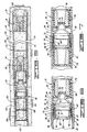
- FIGURE 6 is an enlarged cross-sectional view of the embodiment of baffle assembly shown in FIG. 1 releasably connected within a casing string.
- FIGURE 7 is an enlarged cross-sectional view similar to FIG. 6 showing the baffle assembly after the bottom cementing plug has landed thereon.
- FIGURE 8 is an enlarged cross-sectional view similar to FIG. 6 showing the baffle assembly after it has been released and started moving in the casing string.
- FIGURE 9 is a cross-sectional view of another embodiment of baffle assembly which can be utilized in accordance with the present invention, releasably connected within a casing string.
- FIGURE 10 is an enlarged cross-sectional view of a portion of the baffle assembly of FIG. 9.
- FIGURE 11 is a cross-sectional view similar to FIG. 9 showing the baffle assembly after a bottom cementing plug has landed thereon.
- FIGURE 12 is a cross-sectional view similar to FIG. 9 showing the baffle assembly after it has been released and started moving in the casing string.
- horizontal wells generally include a first vertical or inclined well bore section which is connected to one or more horizontal well bore sections.
- the horizontal well bore section or sections deviate from vertical by at least about 60° and can and often do deviate as much as 90° or greater.
- the string of casing In order to place a string of casing in a well bore including a horizontal well bore section, the string of casing usually must be lowered through the vertical or inclined well bore section and then slid into the horizontal well bore section. Because a great deal of force is often required to slide the casing string into the horizontal well bore section, it has heretofore been necessary to utilize expensive heavy casing joints which include premium thread connections and torque shoulders whereby they resist damage as a result of the high forces exerted on them.
- the methods and apparatus of the present invention may reduce the forces which are required to be exerted on the casing string during placement in a horizontal well, and may eliminate the necessity of using expensive high strength casing joints, and/or allow the use of larger casing sizes in extended reach wells.
- the apparatus of this invention reduces or obviates the requirement of either special surface equipment or the use of any type of work string or line to operate as do some prior art apparatus.
- the apparatus is fluid pressure operated from the surface and may be adaptable to any casing size or type of cementing plug.
- the embodiments of the present invention including selectively openable and movable baffle assemblies which do not require the drill-out of special collars and the like may be used in performing a variety of down hole operations including cementing operations involving selective release cementing plug apparatus and the like.
- the apparatus 10 includes a string of casing 12 which has been placed in a horizontal well bore section 14 while being buoyed up by drilling fluid 16 contained in the well bore 14. The buoying up of the casing string 12 by the drilling fluid 16 allows the casing string 12 to be run or placed in the horizontal well bore section 14 without incurring excessive drag and without requiring excessive forces to be placed on the casing string 12.
- the horizontal casing string 12 is comprised of a plurality of casing joints threadedly connected together and the string of casing 12 is connected to additional casing 28 which extends to the surface through an upwardly extending well bore section (not shown).
- casing is used herein to mean casing, liners or other pipe which is cemented in a well bore.
- the apparatus 10 basically comprises a conventional float shoe 18 connected to a plurality of connected casing joints 20.
- the other end of the connected casing joints 20 is connected to a conventional float collar 22.
- the float shoe 18, the connected joints of casing 20 and the float collar 22 make up a first portion 24 of the casing string 12 which is filled with air (designated by the numeral 25) as will be described further hereinbelow.
- Connected to the opposite end of the float collar 22 from the connected joints of casing 20 is another plurality of connected casing joints 26.
- the other end of the connected casing joints 26 is connected to connected casing joints 28 forming the vertical or inclined section of the well bore (not shown) by a threaded casing collar 30.
- a collet retainer 32 is clamped between the ends of the casing joints 26 and 28 connected by the collar 30, and a selectively openable and releasable closed baffle assembly 34 is releasably connected to the collet retainer 32.
- the connected casing joints 26 between the float collar 22 and the baffle assembly 34 make up a second portion 36 of the casing string 12 which is also filled with air or a low density fluid 38.
- the casing string 12, as well as the additional connected casing joints 28 that extend to the surface, are made up on the surface as the casing is being inserted in the well bore. That is, the float shoe 18 is connected to the end of a first joint of casing 20 and the float shoe and first joint of casing are run into the well. Additional joints of casing 20 are connected to the first joint 20, and the first and additional joints 20 are run into the well without filling them with drilling or other fluid thereby forming the first casing string portion 24 containing only air.
- the float collar 22 is next connected to the casing string portion 24 which traps the air therein followed by the additional casing joints 26 which are connected to the float collar 22 and to each other forming the second casing string portion 36.
- the casing joints 26 forming the casing string portion 36 are connected and run into the well bore, they are filled with air or a low density fluid 38.
- the selectively openable and releasable closed baffle assembly 34 is connected within the interior of the casing string portion 36 which traps the air or low density fluid 38 therein.
- the additional casing joints 28 are connected to the casing string portion 36 while being filled with drilling fluid.
- the casing string portions 24 and 36 containing air 25 and air or low density fluid 38, respectively, are buoyed up by the higher density drilling fluid 16 contained in the well bore 14 as the casing string 12 is inserted in the well bore 14.
- both the float shoe 18 and float collar 22 include spring biased check valves 40A and 40B, respectively, comprised of valves 41A and 41B connected to valve stems 42A and 42B.
- the valves 41A and 41B seat on valve seats 44A and 44B and are urged to the closed position by springs 46A and 46B.
- Both the float shoe 18 and float collar 22 allow pressurized fluid outflow (in directions toward and through the leading end of the casing string 12), but prevent inflow.
- the air trapped within the casing string portion 24 is prevented from entering the casing string portion 36 by the check valve 40B of the float collar 22.
- the air is initially prevented from flowing through the check valve 40A of the float shoe 18 by the bias applied to the valve 41A by the spring 46A. Thereafter, the hydrostatic pressure of the drilling fluid in the well bore is greater than the pressure of the air in the casing string portion 24 which prevents the check valve 40A from opening.
- the portion 36 of the casing string 12 can be filled with a low density fluid other than air to increase the weight of the casing string or for any other reason, the portion 36 will normally be filled with air.
- the low density fluid can be any fluid which is compatible with the drilling fluid used and has a desired density. Examples of such low density fluids are water, aqueous emulsions, aqueous foams, hydrocarbon liquids and the like.
- the drilling fluid 16 contained in the well bore 12, placed in the connected casing joints 28 and circulated through the casing string 12 and annulus 13 can be any conventional weighted drilling fluid.
- the term "drilling fluid” is used herein to mean any fluid utilized to drill the well bore 14 or otherwise circulated into the well bore 14 and/or annulus 13.
- the drilling fluid is an aqueous fluid containing viscosifying agents such as hydratable clays and polymers, weighting materials and other additives. Regardless of the particular type of drilling fluid used, it should have as high a density as is practical without exceeding the fracture gradients of the subterranean zones penetrated by the well bore.
- the drilling fluid has a density in the range of from about 9 to 20 pounds per gallon (1078 to 2396 Kg per m 3 ), more preferably from about 10 to about 18 pounds per gallon (1198 to 2156 Kg per m 3 ) and most preferably from about 12 to about 15.5 pounds per gallon (1438 to 1857 Kg per m 3 ).
- the closed baffle assembly 34 basically comprises a funnel shaped baffle member 50 which is rigidly connected at its enlarged end 51 to a cylindrical collet 52 that is a part of a releasable connector assembly, generally referred to by the numeral 35.
- Conventional O-rings 53 disposed between the baffle member 50 and collet 52 provide a fluid tight seal therebetween.
- the collet 52 includes a plurality of flexible collet fingers 54 having collet heads 56 thereon.
- the collet 52 is disposed within the previously mentioned cylindrical collet retainer 32 which includes an outwardly extending annular lip portion 58 clamped between the ends of a casing joint 26 and a casing joint 28 connected within the threaded casing collar 30.
- a cylindrical collet releasing sleeve 60 is slidably disposed within the collet 52, and at least one shear pin 62 (two are shown) is engaged with the collet 52 and extends into a recess 64 in the releasing sleeve 60.
- An O-ring 61 provides a seal between the releasing sleeve 60 and the collet 52.
- the enlarged collet heads 56 of the collet 52 include outwardly extending portions which form exterior sloping shoulders 55 for contacting a corresponding annular shoulder 57 on the collet retainer 32.
- An O-ring 33 provides a seal between the collet 52 and the collet retainer 32.
- the releasing sleeve 60 contacts the collet heads 56 and prevents them from moving inwardly and disengaging from the collet retainer 32.
- An annular cementing plug landing seat 66 is attached to the releasing sleeve 60.
- valve 72 Attached within the opening 70 formed by the reduced diameter portion 59 of the baffle member 50 is a predetermined fluid pressure operable valve 72. While the valve 72 can take various mechanical forms, it is preferably a rupturable member sealingly attached across the opening 70 in the baffle member 50 which ruptures when a predetermined fluid pressure is exerted thereon.
- a hollow wiper plug 74 is connected to the exterior of the reduced diameter portion 59 of the baffle member 50.
- the wiper plug 74 includes a plurality of resilient wipers 76 which contact the inside surfaces of the casing string 12.
- the air 25 in the casing string 12 is allowed to percolate through the drilling fluid in the casing to the surface. Thereafter, the drilling fluid is circulated through the casing string 12 and into the annulus 13 between the walls of the well bore 14 and the exterior surface of the casing string 12 (FIG. 1).
- a less preferable method of removing the air is to circulate drilling fluid through the baffle assembly 34 and through the drill string 12 whereby the air or low density fluid 38 and air 25 are circulated out of the casing string 12.
- the circulation of drilling fluid for a period of time clears the annulus of debris and conditions it for subsequently receiving a cement slurry.
- a bottom cementing plug 80 is displaced by a surface pumped cement slurry through the connected casing joints 28 to the baffle assembly 34 whereupon the plug 80 lands on the seat 66 of the baffle assembly 34 as shown in FIG. 7.
- the baffle assembly 34 is then released from the collet retainer 32 by increasing the fluid pressure of the cement slurry behind the cement plug 80 to the predetermined fluid pressure required to shear the shear pins 62 and move the releasing sleeve 60 forward.
- the increased pressure of the cement slurry is exerted by way of the cementing plug 80, the seat 66 and the releasing sleeve 60 on the one or more shear pins 62 retaining the releasing sleeve 60 within the collet 52.
- the shear pins 62 are sheared which allows the releasing sleeve 60 to move forward a distance sufficient to free the collet heads 56 of the collet 52.
- the fluid pressure exerted on the cementing plug 80 and baffle assembly 34 causes the collet heads 56 to move inwardly and slide past the collet retainer 32 as the cementing plug 80 and baffle assembly 34 are moved forwardly as shown in FIG. 8.
- the baffle assembly 34 and cementing plug 80 are moved through the casing string 12 to the float collar 22 as will be described further below.
- the baffle assembly 90 includes a threaded casing sub 92 having an annular collet retaining recess 94 formed in an interior surface thereof.
- the casing sub 92 and the other components of the closed baffle assembly 90 connected thereto are threadedly connected between a casing joint 26 and a casing joint 28 previously described.
- a cylindrical collet 96 having a plurality of flexible collet fingers 98 including head portions 100 is disposed within the casing sub 92.
- the head portions 100 of the collet 96 include exterior sloping shoulders 102 thereon which engage a sloping complimentary annular shoulder 104 formed in the interior recess 94 in the casing sub 92.
- a collet releasing sleeve 106 is slidably disposed within the collet 96 which is positioned to engage a cementing plug displaced into landing contact therewith as will be described below.
- the releasing sleeve 106 includes an external annular surface 108 which contacts the head portions 100 of the collet 96 and maintains them in engagement with the recess 94 in the casing sub 92.
- At least one shear pin 110 (two are shown) is engaged with the collet 96 and extends into a recess 112 in the releasing sleeve 106.
- the releasing sleeve 106 is of a size and shape similar to the internal hollow core of a cementing plug and includes a central opening 114 extending therethrough.
- the opposite ends 116 and 118 of the releasing sleeve 106 each include an annular serrated surface 120 and 122, respectively, for preventing the rotation of the releasing sleeve in the event that it and similarly formed cementing plugs are drilled out of the casing string.
- the collet 96 includes an annular recess 124 disposed in an external surface thereof.
- An annular lip seal 126 for providing a seal between the collet 96 and an internal surface of the casing sub 92 is disposed in the recess 124.
- an O-ring 128 is positioned within the recess 124 between a surface of the recess 124 and the lip seal 126.
- the O-ring 128 is positioned within a groove within the recess 124, thereby pre-loading the lip seal 126, between a surface of the recess 124 and the lip seal 126.
- the lip seal 126 is formed of a hard elastomer material which will withstand high fluid pressures without extruding out of the recess 124. However, because of the hardness of the lip seal 126, a relatively high fluid pressure is required to force it into sealing contact with the casing sub 92 when the O-ring 128 is not present. The O-ring 128 is forced towards the enlarged end portion 127 of the lip seal 126 at relatively low pressures thereby moving the lip seal into sealing contact with the interior surface of the casing sub 92 whereby it provides a seal at such low pressures.
- a hollow baffle member 130 which includes a hollow core 131 similar in size and shape to the releasing sleeve 106 and a plurality of wipers 132 for contacting the inside surfaces of the casing string 12, is rigidly attached to the collet 96. Sealingly disposed within the opening 134 extending through the baffle member 130 is a predetermined fluid pressure operable valve 136.
- the valve 136 is preferably a rupturable valve member which ruptures when the predetermined fluid pressure is exerted thereon.
- the baffle member 130 includes opposite annular serrated ends 138 and 140 for engaging the serrated surface 122 of the releasing sleeve 106 and a complimentary serrated surface on a float collar or float shoe when landed thereon. At least one lock ring disposed in a groove, both designated by the numeral 14, are utilized to maintain the collet 96 and other parts of the assembly attached thereto within the casing sub 92.
- the operation of the closed baffle assembly 90 is similar to the operation of the closed baffle assembly 34 described above.
- drilling fluid is pumped into the casing string from the surface to increase the fluid pressure exerted on the closed baffle assembly 90 to cause it to open. That is, the increasing fluid pressure is exerted on the rupturable valve member 136 by way of the hollow interiors of the releasing sleeve 106 and baffle member 130 until the predetermined pressure level required to rupture the rupturable member 136 is reached and the rupturable member 136 ruptures as illustrated in FIGS. 11 and 12. After the opening of the rupturable valve member 136, the air in the casing string is allowed to percolate out of the casing string. Thereafter, the drilling fluid is circulated through the drill string and annulus as previously described in connection with the closed baffle assembly 34.
- a bottom cementing plug 142 which includes a serrated surface 144 that is complimentary to the serrated surface 120 of the releasing sleeve 106 is displaced by a surface pumped cement slurry through the connected casing joints 28 into landing contact with the releasing sleeve 106 as shown in FIG. 11.
- the portion of the closed baffle assembly 90 within the casing sub 92 is then released from the casing sub by increasing the pressure of the cement slurry on the cement plug 142 to the predetermined fluid pressure required.
- the pressure of the cement slurry is increased to a level equal to or greater than the predetermined fluid pressure which is exerted on the shear pins 110 retaining the releasing sleeve 106 within the collet 96 by way of the cementing plug 142 and releasing sleeve 106.
- the shear pins 110 are sheared which allows the releasing sleeve 106 to move forwardly a distance sufficient to release the collet heads 100 from the recess 94 in the casing sub 92.
- the fluid pressure exerted on the cementing plug 142 and the releasing sleeve 106 causes the cementing plug 142, the releasing sleeve 106 and the other internal baffle assembly parts to move toward the leading end of the casing string 12 as shown in FIG. 12.
- the improved methods of the present invention for placing casing in a horizontal well bore section of a horizontal well containing drilling fluid basically comprise the following steps which are described with reference to FIGS. 1-5:
- the cementing plugs 150 and 156, the baffle assembly 34, the float collar 22, set cement in the connected casing joints 20 and the float shoe 18 can all be drilled out of the casing string 12.
- FIG. 1 of the drawings and the reference numerals thereon are referred to.
- An extended reach well bore is drilled into a hydrocarbon producing formation at a depth of about 2,000 feet (610 metres) having a substantially vertical well bore section extending into the formation and a substantially horizontal well bore section extending within the formation for a distance of about 4,000 feet (1220 metres) from a vertical well bore section.
- the horizontal and vertical well bore sections both contain drilling fluid.
- a conventional float shoe 18 is connected to the lower end of a first joint 20 of 7 inch (17.8 cm) casing and the first joint is run in the well followed by 1 or more (generally 1-3) additional 7 inch (17.8 cm) casing joints none of which are filled with drilling or other fluid.
- a float collar 22 is connected to the resulting string of casing which traps the air therein thereby forming a 40-120 foot (12.2 to 36.6 metres) long string of casing between the float shoe 18 and the float collar 22 containing only air.
- a selectively openable and releasable closed baffle assembly 34 is connected within the interior of the portion of the casing string formed by the joints 26 whereby air is trapped therein forming a 3,000-4,000 foot (914 to 1220 metres) portion of the casing string between the float collar 22 and the baffle assembly 34 containing air.
- the baffle assembly 34 includes a predetermined fluid pressure rupturable valve member 72 attached thereto and is connected within the interior of the casing string by a predetermined fluid pressure releasable collet connector 35.
- Additional casing joints 28 are connected to the string of casing above the closed baffle assembly 34 and to each other which are filled with drilling fluid as they are run into the well bore.
- the drilling fluid contained in the well bore and placed within the casing string above the closed baffle assembly is a water based drilling fluid containing hydrated clay, hydrated polymer, weighting material and other additives whereby it has a density of from about 9 to about 20 pounds per gallon (1078 to 2396 Kg per m 3 ).
- the leading portion of the drill string containing air and the following portion containing air are buoyed up by the drilling fluid contained in the horizontal well bore section as the casing string is inserted therein.
- the buoying up of the casing string substantially reduces the drag forces exerted on the casing string as it is slid through the horizontal well bore section.
- Additional casing joints 28 are added to the casing string at the surface until the buoyed up portions of the casing string are placed in a desired location in the horizontal well bore section.
- the closed baffle assembly 34 is opened by exerting the predetermined fluid pressure required to rupture the valve member 72 attached thereto.
- the air in the casing string is allowed to percolate through the casing to the surface, and drilling fluid is then circulated through the casing string and through the annulus whereby the annulus is conditioned for receiving a cement slurry.
- a cement slurry is next flowed through the casing string behind a selectively openable bottom cementing plug whereby the bottom plug is displaced into landing contact with the baffle assembly.
- the baffle assembly is released from its connection with the interior of the string of casing by the exertion of a predetermined fluid pressure on the bottom plug which in turn exerts a force on the releasable fluid pressure operable collet connector 35 so that the baffle assembly is released.
- the flow of the cement slurry through the casing string is continued whereby the bottom plug and baffle assembly are displaced through the casing string into landing contact on the float collar.
- the closed bottom plug is then opened by exerting a predetermined fluid pressure on a rupturable valve member attached thereto so that the cement slurry is flowed through the casing string into the annulus.
- a displacement fluid behind a top cementing plug is next flowed into the casing string whereby the top plug is displaced into landing contact with the bottom plug and the cement slurry is displaced into the annulus. Thereafter the cement slurry is allowed to set into a hard impermeable mass in the annulus.
Landscapes
- Engineering & Computer Science (AREA)
- Life Sciences & Earth Sciences (AREA)
- Geology (AREA)
- Mining & Mineral Resources (AREA)
- Physics & Mathematics (AREA)
- Environmental & Geological Engineering (AREA)
- Fluid Mechanics (AREA)
- General Life Sciences & Earth Sciences (AREA)
- Geochemistry & Mineralogy (AREA)
- Mechanical Engineering (AREA)
- Earth Drilling (AREA)
- Devices For Post-Treatments, Processing, Supply, Discharge, And Other Processes (AREA)
Description
- The present invention relates to a method and apparatus for placing and cementing casing in a horizontal well.
- In recent years, the drilling and completion of horizontal wells has increased appreciably. A horizontal well is one which includes one or more horizontal well bore sections, i.e. well bores drilled at an angle from vertical of about 60° or greater. The horizontal well bore section or sections usually extend from a vertical or inclined well bore section. The drilling of a horizontal well bore section in a hydrocarbon producing zone allows more of the zone to be in direct contact with the well bore which results in a higher displacement efficiency of the zone as a whole. In some "extended reach wells", the horizontal well bore sections frequently approach 90° from vertical and the horizontal well bore sections are longer than the vertical sections.
- In completing a horizontal well, a casing string usually must be run into the horizontal well bore section by sliding it through the well bore. The high drag forces exerted on the casing string can damage the casing joints at their threaded connections. As a result, expensive heavy casing joints with premium thread connections and torque shoulders have been utilized. The casing string can also become stuck as a result of differential pressures which requires the application of additional forces on the casing string to overcome. If sufficient additional forces cannot be applied, the stuck pipe may result in the loss of the well.
- Various techniques have heretofor been developed and used for decreasing the forces required to run casing strings in horizontal wells. For example, the well bore drilling fluid has been replaced with a high density fluid prior to running a casing string in a horizontal well bore section to provide buoyant forces on the casing. In addition, a retrievable packer has been included in the casing string for the purpose of trapping a fluid lighter than the well bore fluids between the packer and the end of the casing string. U.S. Patent No. 4,986,361 dated January 22, 1991, U.S. Patent No. 5,117,915 dated June 2, 1992 and U.S. Patent No. 5,181,571 dated January 26, 1993, all issued to Mueller et al., disclose apparatus for trapping air in the leading portion of a casing string to thereby increase the buoyancy of the casing string in drilling fluid contained in the well bore. In one embodiment, the apparatus includes a float shoe and a sliding air trapping insert in the casing string. The air trapping insert is opened to allow fluid circulation and then moved to a position adjacent the float shoe when a cementing plug followed by a cement slurry is pumped into contact with the insert. Thereafter the cement slurry is pumped into the annulus and allowed to set.
- While the above and other methods and apparatus have been utilized successfully, there is still a need for improved methods and apparatus for reducing casing string drag and reducing or eliminating the need for the use of expensive heavy casing joints to prevent damage as a result of excessive forces exerted on the casing string.
- We have now devised a method and apparatus which meet or reduce the problems associated with the prior art.
- WO 91 03620 discloses a device for and method of placing a casing in a horizontal well bore section of a horizontal well, in which a float shoe and a landing collar are attached at a first end of a portion of a casing spring, and sliding air trapping insert is inserted at the other end. The air trapping insert includes a fluid flow passageway blocked by a plug attached by shear pins to the insert, and the air trapping insert and float shoe together form an air cavity within the string portion. The air cavity thereby produces buoyant forces during running, cementing or other casing operation within the well bore.
- US-A-5150756 discloses another well completion apparatus which includes a tool adaptor to be connected to a casing string and having a plug therein above a back pressure valve installed in the lower end of the sting to form a buoyant chamber within the casing spring, the chamber is filled with a low density fluid for lowing into a substantially horizontally extending lower end of a well bore.
- EP-A-0697496 discloses a well cementing plug assembly which comprises top and bottom cementing plugs, each including a high strength inner tube for supporting high differential pressures exhorted on the plugs. The bottom end of the inner tube of the bottom plug is adapted to supportingly engage a float tube or the like upon landing.
- According to one aspect of the present invention there is provided a selectively operable and releasable closed baffle assembly for attachment within a pipe string, which baffle assembly comprises an internal collet retainer adapted to be connected to said pipe string; a cylindrical collet disposed within and retained by said collet retainer having an annular recess form in an exterior surface thereof; an annular lip seal disposed in said recess for providing a seal between said collet and the interior surface of said pipe string; an O-ring disposed in said recess between said collet and said lip seal for facilitating the movement of said lip seal into sealing contact with said interior surface of said pipe string; a collet releasing sleeve slidably disposed within said collet positioned to engage a cementing plug displaced into landing contact therewith; at least one shear pin engaged with said collet and extending into a recess in said collet releasing sleeve, said shear pin shearing when a predetermined fluid pressure is exerted on said releasing sleeve by a cementing plug landed thereon; a baffle member sealingly connected to said collet having an opening therethrough; and a predetermined fluid pressure operable valve means sealingly attached to said opening in said baffle member.
- In a further aspect, the present invention provides an apparatus for facilitating the placement of a casing string in a horizontal well bore section of a horizontal well containing drilling fluid, said apparatus comprising a float shoe attached to the end of said casing string which first enters said horizontal well bore section during placement; and a collar connected in said casing string for trapping air in a first portion of said casing string thereby causing said first portion to be buoyed up during placement in said horizontal well bore section by said drilling fluid therein whereby drag on first portion is reduced, characterised in that the collar is a flood collar; and a selectively openable and releasable closed baffle assembly according to the first aspect of the invention is connected in said casing string for trapping air or a low density fluid in a second portion of said casing string thereby causing said second portion to be buoyed up during placement in said horizontal well bore section by said drilling fluid therein, whereby drag on said second portion is reduced.
- In a further aspect, the present invention includes A method of placing casing (12) in a horizontal well bore section (14) of a horizontal well which section contains drilling fluid, the method comprising the step of connecting a selectively openable and releasable closed baffle assembly according to any of
claims 1 to 4 within the interior of a string of casing thereby trapping air or low density fluid within a portion of said string of casing between a float collar and said baffle assembly whereby that portion of said string of casing and a portion filled with air between said float collar and a float shoe are buoyed up by drilling fluid in said horizontal well bore section of said well thereby reducing the drag on said portions during their placement in said horizontal well bore section, said baffle assembly being closed by a predetermined fluid pressure operable valve member attached thereto and being connect within the interior of said string of casing by a releasable fluid pressure operable connector attached thereto. - The improved method according to the invention for placing and cementing casing in a horizontal well bore section of a horizontal well containing drilling fluid preferably includes the further steps of connecting a float shoe to the lower end of a first joint of casing and running the first joint of casing into the well. Additional joints of casing are connected to the first joint and to each other which are run into the well without being filled with fluid thereby forming a string of casing containing only air. A float collar is connected to the string of casing containing air to trap the air therein, and additional joints of casing are connected to the float collar which are filled with air or other low density fluid as they are run into the well. The selectively openable and releasable closed baffle assembly is next connected within the interior of the string of casing which traps the air or low density fluid within the portion of the string of casing between the float collar and the baffle assembly whereby that portion of the string of casing and the portion of the string of casing between the float shoe and float collar filled with air are buoyed up by drilling fluid in the horizontal well bore section as the string of casing is run therein. Additional joints of casing are connected to the string of casing above the closed baffle assembly and such joints are filled with drilling fluid as they are run into the well. After the string of casing has been placed in the well, the closed baffle assembly is opened whereby the low density fluid and/or air percolates up through the drilling fluid in the casing to the surface. If desired, the low density fluid and/or air can be displaced through the string of casing into the annulus between the string of casing and the well and circulated to the surface. Thereafter, a cement slurry is flowed through the string of casing into the annulus and allowed to set into a hard impermeable mass therein.
- In order that the invention may be more fully understood, embodiments thereof will now be described by way of illustration only, with reference to the accompanying drawings, in which:
- FIGURE 1 is a side cross-sectional view of a horizontal well bore section having a casing string including one embodiment of apparatus of the present invention disposed therein.
- FIGURE 2 is a cross-sectional view similar to FIG. 1 showing the casing string apparatus after a baffle assembly has been opened and drilling fluid circulated through the drill string into the annulus.
- FIGURE 3 is a cross-sectional view similar to FIG. 1 showing the casing string apparatus after a bottom cement plug displaced by a cement slurry has landed on the baffle assembly.
- FIGURE 4 is a cross-sectional view similar to FIG. 1 showing the casing string apparatus after the baffle assembly has been released and it and the bottom cementing plug have landed on a float collar.
- FIGURE 5 is a cross-sectional view similar to FIG. I showing the casing string apparatus after the cement slurry has flowed through the casing string into the annulus and a top cementing plug has landed on the bottom cementing plug.
- FIGURE 6 is an enlarged cross-sectional view of the embodiment of baffle assembly shown in FIG. 1 releasably connected within a casing string.
- FIGURE 7 is an enlarged cross-sectional view similar to FIG. 6 showing the baffle assembly after the bottom cementing plug has landed thereon.
- FIGURE 8 is an enlarged cross-sectional view similar to FIG. 6 showing the baffle assembly after it has been released and started moving in the casing string.
- FIGURE 9-is a cross-sectional view of another embodiment of baffle assembly which can be utilized in accordance with the present invention, releasably connected within a casing string.
- FIGURE 10 is an enlarged cross-sectional view of a portion of the baffle assembly of FIG. 9.
- FIGURE 11 is a cross-sectional view similar to FIG. 9 showing the baffle assembly after a bottom cementing plug has landed thereon.
- FIGURE 12 is a cross-sectional view similar to FIG. 9 showing the baffle assembly after it has been released and started moving in the casing string.
- As is well understood, horizontal wells generally include a first vertical or inclined well bore section which is connected to one or more horizontal well bore sections. The horizontal well bore section or sections deviate from vertical by at least about 60° and can and often do deviate as much as 90° or greater. In order to place a string of casing in a well bore including a horizontal well bore section, the string of casing usually must be lowered through the vertical or inclined well bore section and then slid into the horizontal well bore section. Because a great deal of force is often required to slide the casing string into the horizontal well bore section, it has heretofore been necessary to utilize expensive heavy casing joints which include premium thread connections and torque shoulders whereby they resist damage as a result of the high forces exerted on them. The methods and apparatus of the present invention may reduce the forces which are required to be exerted on the casing string during placement in a horizontal well, and may eliminate the necessity of using expensive high strength casing joints, and/or allow the use of larger casing sizes in extended reach wells. In addition, the apparatus of this invention reduces or obviates the requirement of either special surface equipment or the use of any type of work string or line to operate as do some prior art apparatus. Further, the apparatus is fluid pressure operated from the surface and may be adaptable to any casing size or type of cementing plug. Also, the embodiments of the present invention including selectively openable and movable baffle assemblies which do not require the drill-out of special collars and the like may be used in performing a variety of down hole operations including cementing operations involving selective release cementing plug apparatus and the like.
- Referring now to the drawings, and particularly to FIG. 1, the improved apparatus of the present invention for placing and cementing a string of casing in a horizontal well is illustrated and generally designated by the
numeral 10. Theapparatus 10 includes a string ofcasing 12 which has been placed in a horizontalwell bore section 14 while being buoyed up by drillingfluid 16 contained in thewell bore 14. The buoying up of thecasing string 12 by thedrilling fluid 16 allows thecasing string 12 to be run or placed in the horizontalwell bore section 14 without incurring excessive drag and without requiring excessive forces to be placed on thecasing string 12. As will be understood by those skilled in the art, thehorizontal casing string 12 is comprised of a plurality of casing joints threadedly connected together and the string ofcasing 12 is connected toadditional casing 28 which extends to the surface through an upwardly extending well bore section (not shown). The term "casing" is used herein to mean casing, liners or other pipe which is cemented in a well bore. - The
apparatus 10 basically comprises aconventional float shoe 18 connected to a plurality of connectedcasing joints 20. The other end of the connected casing joints 20 is connected to aconventional float collar 22. Thefloat shoe 18, the connected joints ofcasing 20 and thefloat collar 22 make up afirst portion 24 of thecasing string 12 which is filled with air (designated by the numeral 25) as will be described further hereinbelow. Connected to the opposite end of thefloat collar 22 from the connected joints ofcasing 20 is another plurality of connected casing joints 26. The other end of the connected casing joints 26 is connected to connected casing joints 28 forming the vertical or inclined section of the well bore (not shown) by a threadedcasing collar 30. Acollet retainer 32 is clamped between the ends of the casing joints 26 and 28 connected by thecollar 30, and a selectively openable and releasableclosed baffle assembly 34 is releasably connected to thecollet retainer 32. The connected casing joints 26 between thefloat collar 22 and thebaffle assembly 34 make up asecond portion 36 of thecasing string 12 which is also filled with air or alow density fluid 38. - The
casing string 12, as well as the additional connected casing joints 28 that extend to the surface, are made up on the surface as the casing is being inserted in the well bore. That is, thefloat shoe 18 is connected to the end of a first joint ofcasing 20 and the float shoe and first joint of casing are run into the well. Additional joints ofcasing 20 are connected to the first joint 20, and the first andadditional joints 20 are run into the well without filling them with drilling or other fluid thereby forming the firstcasing string portion 24 containing only air. Thefloat collar 22 is next connected to thecasing string portion 24 which traps the air therein followed by theadditional casing joints 26 which are connected to thefloat collar 22 and to each other forming the secondcasing string portion 36. As the casing joints 26 forming thecasing string portion 36 are connected and run into the well bore, they are filled with air or alow density fluid 38. The selectively openable and releasableclosed baffle assembly 34 is connected within the interior of thecasing string portion 36 which traps the air orlow density fluid 38 therein. Thereafter, theadditional casing joints 28 are connected to thecasing string portion 36 while being filled with drilling fluid. As mentioned, thecasing string portions air 25 and air orlow density fluid 38, respectively, are buoyed up by the higherdensity drilling fluid 16 contained in the well bore 14 as thecasing string 12 is inserted in the well bore 14. - The structure and operation of the
float shoe 18 andfloat collar 22 are conventional and well understood. As illustrated in the drawings, both thefloat shoe 18 andfloat collar 22 include springbiased check valves valve seats 44A and 44B and are urged to the closed position bysprings 46A and 46B. Both thefloat shoe 18 andfloat collar 22 allow pressurized fluid outflow (in directions toward and through the leading end of the casing string 12), but prevent inflow. Thus, the air trapped within thecasing string portion 24 is prevented from entering thecasing string portion 36 by thecheck valve 40B of thefloat collar 22. The air is initially prevented from flowing through thecheck valve 40A of thefloat shoe 18 by the bias applied to the valve 41A by thespring 46A. Thereafter, the hydrostatic pressure of the drilling fluid in the well bore is greater than the pressure of the air in thecasing string portion 24 which prevents thecheck valve 40A from opening. - While, as indicated above, the
portion 36 of thecasing string 12 can be filled with a low density fluid other than air to increase the weight of the casing string or for any other reason, theportion 36 will normally be filled with air. When used, the low density fluid can be any fluid which is compatible with the drilling fluid used and has a desired density. Examples of such low density fluids are water, aqueous emulsions, aqueous foams, hydrocarbon liquids and the like. - The
drilling fluid 16 contained in the well bore 12, placed in the connected casing joints 28 and circulated through thecasing string 12 andannulus 13 can be any conventional weighted drilling fluid. The term "drilling fluid" is used herein to mean any fluid utilized to drill the well bore 14 or otherwise circulated into the well bore 14 and/orannulus 13. Most commonly, the drilling fluid is an aqueous fluid containing viscosifying agents such as hydratable clays and polymers, weighting materials and other additives. Regardless of the particular type of drilling fluid used, it should have as high a density as is practical without exceeding the fracture gradients of the subterranean zones penetrated by the well bore. Generally, the drilling fluid has a density in the range of from about 9 to 20 pounds per gallon (1078 to 2396 Kg per m3), more preferably from about 10 to about 18 pounds per gallon (1198 to 2156 Kg per m3) and most preferably from about 12 to about 15.5 pounds per gallon (1438 to 1857 Kg per m3). - Referring now to FIGS. 6-8, and particularly to FIG. 6, the selectively openable and releasable
closed baffle assembly 34 is illustrated in enlarged detail releasably connected within the secondcasing string portion 36 of thecasing string 12. Theclosed baffle assembly 34 basically comprises a funnel shapedbaffle member 50 which is rigidly connected at itsenlarged end 51 to acylindrical collet 52 that is a part of a releasable connector assembly, generally referred to by the numeral 35. Conventional O-rings 53 disposed between thebaffle member 50 andcollet 52 provide a fluid tight seal therebetween. Thecollet 52 includes a plurality offlexible collet fingers 54 having collet heads 56 thereon. Thecollet 52 is disposed within the previously mentionedcylindrical collet retainer 32 which includes an outwardly extendingannular lip portion 58 clamped between the ends of a casing joint 26 and a casing joint 28 connected within the threadedcasing collar 30. - A cylindrical
collet releasing sleeve 60 is slidably disposed within thecollet 52, and at least one shear pin 62 (two are shown) is engaged with thecollet 52 and extends into arecess 64 in the releasingsleeve 60. An O-ring 61 provides a seal between the releasingsleeve 60 and thecollet 52. - The enlarged collet heads 56 of the
collet 52 include outwardly extending portions which formexterior sloping shoulders 55 for contacting a correspondingannular shoulder 57 on thecollet retainer 32. An O-ring 33 provides a seal between thecollet 52 and thecollet retainer 32. The releasingsleeve 60 contacts the collet heads 56 and prevents them from moving inwardly and disengaging from thecollet retainer 32. An annular cementingplug landing seat 66 is attached to the releasingsleeve 60. - Attached within the
opening 70 formed by the reduceddiameter portion 59 of thebaffle member 50 is a predetermined fluid pressureoperable valve 72. While thevalve 72 can take various mechanical forms, it is preferably a rupturable member sealingly attached across theopening 70 in thebaffle member 50 which ruptures when a predetermined fluid pressure is exerted thereon. - A
hollow wiper plug 74 is connected to the exterior of the reduceddiameter portion 59 of thebaffle member 50. The wiper plug 74 includes a plurality ofresilient wipers 76 which contact the inside surfaces of thecasing string 12. - In the operation of the closed baffle assembly 34 (referring to FIGS. 6-8), after the
casing string 12 has been placed in the horizontalwell bore section 14, drilling fluid is pumped into the casing string at the surface to increase the fluid pressure within the connected casing joints 28 to the predetermined fluid pressure level required to open thevalve 72 in thebaffle assembly 34. That is, fluid pressure is exerted on therupturable member 72 by way of the hollow interiors of thereleasable connector assembly 35 and thebaffle member 50 until the predetermined pressure level required to rupture therupturable member 72 is equaled or exceeded, and therupturable member 72 ruptures as illustrated in FIG. 7. After the rupture of therupturable member 70, theair 25 in thecasing string 12 is allowed to percolate through the drilling fluid in the casing to the surface. Thereafter, the drilling fluid is circulated through thecasing string 12 and into theannulus 13 between the walls of the well bore 14 and the exterior surface of the casing string 12 (FIG. 1). As mentioned, a less preferable method of removing the air is to circulate drilling fluid through thebaffle assembly 34 and through thedrill string 12 whereby the air orlow density fluid 38 andair 25 are circulated out of thecasing string 12. The circulation of drilling fluid for a period of time clears the annulus of debris and conditions it for subsequently receiving a cement slurry. - After the above mentioned circulation has been completed, a
bottom cementing plug 80 is displaced by a surface pumped cement slurry through the connected casing joints 28 to thebaffle assembly 34 whereupon theplug 80 lands on theseat 66 of thebaffle assembly 34 as shown in FIG. 7. Thebaffle assembly 34 is then released from thecollet retainer 32 by increasing the fluid pressure of the cement slurry behind thecement plug 80 to the predetermined fluid pressure required to shear the shear pins 62 and move the releasingsleeve 60 forward. That is, the increased pressure of the cement slurry is exerted by way of the cementingplug 80, theseat 66 and the releasingsleeve 60 on the one or more shear pins 62 retaining the releasingsleeve 60 within thecollet 52. As a result and as shown in FIG. 7, the shear pins 62 are sheared which allows the releasingsleeve 60 to move forward a distance sufficient to free the collet heads 56 of thecollet 52. Once the collet heads 56 are free to move inwardly, the fluid pressure exerted on the cementingplug 80 and baffleassembly 34 causes the collet heads 56 to move inwardly and slide past thecollet retainer 32 as the cementingplug 80 and baffleassembly 34 are moved forwardly as shown in FIG. 8. Thebaffle assembly 34 and cementingplug 80 are moved through thecasing string 12 to thefloat collar 22 as will be described further below. - Referring now to FIGS. 9-12, and particularly to FIGS. 9 and 10, an alternate embodiment of the selectively openable and releasable closed baffle assembly of this invention, generally designated by the numeral 90, is illustrated. Instead of the
collet retainer 32 clamped between adjacent casing joints as is utilized by theclosed baffle assembly 34 described above, thebaffle assembly 90 includes a threadedcasing sub 92 having an annularcollet retaining recess 94 formed in an interior surface thereof. Thecasing sub 92 and the other components of theclosed baffle assembly 90 connected thereto are threadedly connected between a casing joint 26 and a casing joint 28 previously described. - A
cylindrical collet 96 having a plurality offlexible collet fingers 98 includinghead portions 100 is disposed within thecasing sub 92. Thehead portions 100 of thecollet 96 includeexterior sloping shoulders 102 thereon which engage a sloping complimentaryannular shoulder 104 formed in theinterior recess 94 in thecasing sub 92. - A
collet releasing sleeve 106 is slidably disposed within thecollet 96 which is positioned to engage a cementing plug displaced into landing contact therewith as will be described below. The releasingsleeve 106 includes an externalannular surface 108 which contacts thehead portions 100 of thecollet 96 and maintains them in engagement with therecess 94 in thecasing sub 92. At least one shear pin 110 (two are shown) is engaged with thecollet 96 and extends into arecess 112 in the releasingsleeve 106. The releasingsleeve 106 is of a size and shape similar to the internal hollow core of a cementing plug and includes acentral opening 114 extending therethrough. The opposite ends 116 and 118 of the releasingsleeve 106 each include an annularserrated surface - As best shown in FIG. 10, the
collet 96 includes anannular recess 124 disposed in an external surface thereof. Anannular lip seal 126 for providing a seal between thecollet 96 and an internal surface of thecasing sub 92 is disposed in therecess 124. In addition, an O-ring 128 is positioned within therecess 124 between a surface of therecess 124 and thelip seal 126. Alternatively, the O-ring 128 is positioned within a groove within therecess 124, thereby pre-loading thelip seal 126, between a surface of therecess 124 and thelip seal 126. When fluid pressure is applied to the O-ring 128 and thelip seal 126, the O-ring 128 is forced towards theenlarged end portion 127 of thelip seal 126 which in turn forces thelip seal 126 into contact with the interior surface of thecasing sub 92 whereby a seal is provided between thecasing sub 92 and thecollet 96. Thelip seal 126 is formed of a hard elastomer material which will withstand high fluid pressures without extruding out of therecess 124. However, because of the hardness of thelip seal 126, a relatively high fluid pressure is required to force it into sealing contact with thecasing sub 92 when the O-ring 128 is not present. The O-ring 128 is forced towards theenlarged end portion 127 of thelip seal 126 at relatively low pressures thereby moving the lip seal into sealing contact with the interior surface of thecasing sub 92 whereby it provides a seal at such low pressures. - A
hollow baffle member 130, which includes ahollow core 131 similar in size and shape to the releasingsleeve 106 and a plurality ofwipers 132 for contacting the inside surfaces of thecasing string 12, is rigidly attached to thecollet 96. Sealingly disposed within theopening 134 extending through thebaffle member 130 is a predetermined fluid pressureoperable valve 136. Thevalve 136 is preferably a rupturable valve member which ruptures when the predetermined fluid pressure is exerted thereon. Like the releasingsleeve 106, thebaffle member 130 includes opposite annular serrated ends 138 and 140 for engaging theserrated surface 122 of the releasingsleeve 106 and a complimentary serrated surface on a float collar or float shoe when landed thereon. At least one lock ring disposed in a groove, both designated by the numeral 14, are utilized to maintain thecollet 96 and other parts of the assembly attached thereto within thecasing sub 92. - The operation of the
closed baffle assembly 90 is similar to the operation of theclosed baffle assembly 34 described above. Referring to FIGS. 11 and 12, after the casing string within which theclosed baffle assembly 90 is attached has been placed in a horizontal well bore section, drilling fluid is pumped into the casing string from the surface to increase the fluid pressure exerted on theclosed baffle assembly 90 to cause it to open. That is, the increasing fluid pressure is exerted on therupturable valve member 136 by way of the hollow interiors of the releasingsleeve 106 andbaffle member 130 until the predetermined pressure level required to rupture therupturable member 136 is reached and therupturable member 136 ruptures as illustrated in FIGS. 11 and 12. After the opening of therupturable valve member 136, the air in the casing string is allowed to percolate out of the casing string. Thereafter, the drilling fluid is circulated through the drill string and annulus as previously described in connection with theclosed baffle assembly 34. - After the circulation of drilling fluid has been completed, a
bottom cementing plug 142 which includes aserrated surface 144 that is complimentary to theserrated surface 120 of the releasingsleeve 106 is displaced by a surface pumped cement slurry through the connected casing joints 28 into landing contact with the releasingsleeve 106 as shown in FIG. 11. The portion of theclosed baffle assembly 90 within thecasing sub 92 is then released from the casing sub by increasing the pressure of the cement slurry on thecement plug 142 to the predetermined fluid pressure required. That is, the pressure of the cement slurry is increased to a level equal to or greater than the predetermined fluid pressure which is exerted on the shear pins 110 retaining the releasingsleeve 106 within thecollet 96 by way of the cementingplug 142 and releasingsleeve 106. As a result and as shown in FIG. 12, the shear pins 110 are sheared which allows the releasingsleeve 106 to move forwardly a distance sufficient to release the collet heads 100 from therecess 94 in thecasing sub 92. Once the collet heads 100 are released, the fluid pressure exerted on the cementingplug 142 and the releasingsleeve 106 causes the cementingplug 142, the releasingsleeve 106 and the other internal baffle assembly parts to move toward the leading end of thecasing string 12 as shown in FIG. 12. - The improved methods of the present invention for placing casing in a horizontal well bore section of a horizontal well containing drilling fluid basically comprise the following steps which are described with reference to FIGS. 1-5:
- (1) connecting the
float shoe 18 to the lower end of a first joint ofcasing 20 and running the first joint 20 into the well without filling it with drilling fluid, - (2) connecting
additional casing joints 20 to the first joint 20 as theadditional joints 20 are run into the well without filling the additional joints with drilling fluid thereby forming a string of casing containing onlyair 25, - (3) connecting the
float collar 22 to the connected casing joints 20 to thereby trap theair 25 in the connected casing joints 20, - (4) connecting
additional casing joints 26 to thefloat collar 22 without filling theconnected joints 26 or filling theconnected joints 26 with a low density fluid other than air as thejoints 26 are run into the well, - (5) connecting the closed baffle assembly 34 (or the closed
baffle assembly 90) within the interior of the connected casing
joints 26 thereby trapping the air or other
low density fluid 38 within the connected casing joints 26 whereby theportion 36 of thecasing string 12 filled with air orlow density fluid 38 and theportion 24 filled withair 25 are buoyed up by drillingfluid 16 in the horizontalwell bore section 14 thereby reducing the drag on those portions during their placement in the horizontalwell bore section 14, - (6) connecting
additional casing joints 28 to the string ofcasing 12 and filling the additional joints withdrilling fluid 16 as they are run into the well until the buoyed upportions casing 12 are placed in a desired location in the horizontalwell bore section 14, and - (7) opening the
closed baffle assembly 34 by exerting thereon the predetermined fluid pressure required to rupture therupturable valve member 72 thereof as shown in FIG. 2. After the string ofcasing 12 has been placed and the predetermined fluid pressureoperable valve 72 of theclosed baffle assembly 34 has been opened, the following additional steps are performed to cement thecasing string 12 in the horizontalwell bore section 14, - (8) allowing the
air 25 to percolate out of thecasing string 12 or circulating the air out and flowing drilling fluid through thecasing string 12 into theannulus 13 to condition theannulus 13 for receiving a cement slurry as shown in FIG. 2, - (9) flowing a
cement slurry 152 behind a selectively openablebottom cementing plug 150 into thecasing string 12 whereby thebottom plug 150 is displaced into landing contact with thebaffle assembly 34, - (10) releasing the
baffle assembly 34 from its connection with the string ofcasing 12 by exerting the predetermined fluid pressure by way of thebottom plug 150 on thebaffle assembly 34 required to release thebaffle assembly 34, - (11) continuing the flow of the
cement slurry 152 whereby thebottom plug 150 and thebaffle assembly 34 are displaced through the string ofcasing 12 and land on thefloat collar 22 as shown in FIG. 4, - (12) opening the
bottom plug 150 by exerting the predetermined fluid pressure on thebottom plug 150 required to rupture therupturable valve member 154 attached thereto as shown in FIG. 5, - (13) flowing a
displacement fluid 158 behind atop cementing plug 156 into thecasing string 12 whereby thetop plug 156 is displaced into landing contact with thebottom plug 150 and thecement slurry 152 is displaced into theannulus 13 as illustrated in FIG. 5, and - (14) allowing the
cement slurry 152 to set into a hard impermeable mass in theannulus 13. -
- As will be understood by those skilled in the art, after the cement slurry has set in the annulus, if it is necessary or desirable, the cementing plugs 150 and 156, the
baffle assembly 34, thefloat collar 22, set cement in the connected casing joints 20 and thefloat shoe 18 can all be drilled out of thecasing string 12. - In order to further illustrate the methods and apparatus of this invention, the following Example is given by way of illustration only. In the Example, FIG. 1 of the drawings and the reference numerals thereon are referred to.
- An extended reach well bore is drilled into a hydrocarbon producing formation at a depth of about 2,000 feet (610 metres) having a substantially vertical well bore section extending into the formation and a substantially horizontal well bore section extending within the formation for a distance of about 4,000 feet (1220 metres) from a vertical well bore section. After the drilling is completed, the horizontal and vertical well bore sections both contain drilling fluid.
- A
conventional float shoe 18 is connected to the lower end of a first joint 20 of 7 inch (17.8 cm) casing and the first joint is run in the well followed by 1 or more (generally 1-3) additional 7 inch (17.8 cm) casing joints none of which are filled with drilling or other fluid. Afloat collar 22 is connected to the resulting string of casing which traps the air therein thereby forming a 40-120 foot (12.2 to 36.6 metres) long string of casing between thefloat shoe 18 and thefloat collar 22 containing only air. - 80-100 additional 7 inch (17.8 cm) casing joints 26 are connected to the
float collar 22 and to each other which are also not filled with drilling or other fluid. A selectively openable and releasableclosed baffle assembly 34 is connected within the interior of the portion of the casing string formed by thejoints 26 whereby air is trapped therein forming a 3,000-4,000 foot (914 to 1220 metres) portion of the casing string between thefloat collar 22 and thebaffle assembly 34 containing air. Thebaffle assembly 34 includes a predetermined fluid pressurerupturable valve member 72 attached thereto and is connected within the interior of the casing string by a predetermined fluid pressurereleasable collet connector 35. - Additional casing joints 28 are connected to the string of casing above the
closed baffle assembly 34 and to each other which are filled with drilling fluid as they are run into the well bore. The drilling fluid contained in the well bore and placed within the casing string above the closed baffle assembly is a water based drilling fluid containing hydrated clay, hydrated polymer, weighting material and other additives whereby it has a density of from about 9 to about 20 pounds per gallon (1078 to 2396 Kg per m3). - The leading portion of the drill string containing air and the following portion containing air are buoyed up by the drilling fluid contained in the horizontal well bore section as the casing string is inserted therein. The buoying up of the casing string substantially reduces the drag forces exerted on the casing string as it is slid through the horizontal well bore section. Additional casing joints 28 are added to the casing string at the surface until the buoyed up portions of the casing string are placed in a desired location in the horizontal well bore section.
- After placement of the casing string, the
closed baffle assembly 34 is opened by exerting the predetermined fluid pressure required to rupture thevalve member 72 attached thereto. The air in the casing string is allowed to percolate through the casing to the surface, and drilling fluid is then circulated through the casing string and through the annulus whereby the annulus is conditioned for receiving a cement slurry. - A cement slurry is next flowed through the casing string behind a selectively openable bottom cementing plug whereby the bottom plug is displaced into landing contact with the baffle assembly. The baffle assembly is released from its connection with the interior of the string of casing by the exertion of a predetermined fluid pressure on the bottom plug which in turn exerts a force on the releasable fluid pressure
operable collet connector 35 so that the baffle assembly is released. - The flow of the cement slurry through the casing string is continued whereby the bottom plug and baffle assembly are displaced through the casing string into landing contact on the float collar. The closed bottom plug is then opened by exerting a predetermined fluid pressure on a rupturable valve member attached thereto so that the cement slurry is flowed through the casing string into the annulus. A displacement fluid behind a top cementing plug is next flowed into the casing string whereby the top plug is displaced into landing contact with the bottom plug and the cement slurry is displaced into the annulus. Thereafter the cement slurry is allowed to set into a hard impermeable mass in the annulus.
Claims (17)
- A selectively operable and releasable closed baffle assembly (90) for attachment within a pipe string (12), which baffle assembly comprises an internal collet retainer adapted to be connected to said pipe string (12); a cylindrical collet (96) disposed within and retained by said collet retainer having an annular recess (124) formed in an exterior surface thereof; an annular lip seal (126) disposed in said recess (124) for providing a seal between said collet (96) and the interior surface of said pipe string; an O-ring (120) disposed in said recess (124) between said collet (96) and said lip seal (126) for facilitating the movement of said lip seal (126) into sealing contact with said interior surface of said pipe string (12); a collet releasing sleeve (106) slidably disposed within said collet (96) positioned to engage a cementing plug (142) displaced into landing contact therewith; at least one shear pin (11) engaged with said collet (96) and extending into a recess (112) in said collet releasing sleeve (106), said shear pin (110) shearing when a predetermined fluid pressure is exerted on said releasing sleeve (106) by a cementing plug (142) landed thereon; a baffle member (90) sealingly connected to said collet (96) having an opening (114) therethrough; and a predetermined fluid pressure operable valve means (136) sealingly attached to said opening (114) in said baffle member (90).
- A assembly according to claim 1, wherein said collet retaining is a threaded pipe sub (92) having an annular collet retaining recess (94) formed in an interior surface thereof threadedly connected in said pipe string (12).
- An assembly according to claim 1 or claim 2, wherein said closed baffle assembly (34; 90) further comprises slidable wiper means (76; 132) attached thereto.
- An assembly according to any of claims I to 3, wherein said closed baffle assembly (34; 90) further comprises a seat (66; 120) for sealingly receiving said cementing plug (80; 150; 142) attached to said releasing sleeve (60; 106).
- An apparatus (10) for facilitating the placement of a casing string (12) in a horizontal well bore section (14) of a horizontal well containing drilling fluid (16), said apparatus comprising a float shoe (18) attached to the end of said casing string (12) which first enters said horizontal well bore section (14) during placement; and a collar (22) connected in said casing string (12) for trapping air (25) in a first portion (24) of said casing string (12) thereby causing said first portion (24) to be buoyed up during placement in said horizontal well bore section (14) by said drilling fluid (16) therein whereby drag on first portion (24) is reduced, characterised in that the collar (22) is a flood collar, and a selectively operable and releasable closed baffle assembly (34; 90) according to any of the preceding claims is connected in said casing string (12) for trapping air (25) or a low density fluid (38) in a second portion (36) of said casing string (12) thereby causing said second portion (36) to be buoyed up during placement in said horizontal well bore section (14) by said drilling fluid (16) therein, whereby drag on said second portion (36) is reduced.
- An apparatus according to claim 5, wherein said closed baffle. assembly (34; 90) includes a predetermined fluid pressure operable valve (72; 136) attached there to and a predetermined fluid pressure operable releasable connector assembly (35) by means of which it is connected in said string casing (12).
- An apparatus according to claim 6, wherein said predetermined fluid pressure operable valve (72; 136) attached to said closed baffle assembly (34; 90) is comprised of a rupturable member sealingly attached over an opening (70; 114) in said baffle assembly (34; 90) which ruptures when said predetermined fluid pressure is exerted thereon.
- An apparatus according to claim 6 or claim 7, wherein said predetermined fluid pressure operable releasable container assembly (35) attached to said baffle means (90) comprises: a threaded casing sub (92) having the annular collet retaining recess (94) formed in an interior surface thereof threadedly connected to said casing string (12); the cylindrical collet (96) being disposed within said sub (92) and retained therein by said retaining recess (94); and a cementing plug (80; 150; 142) adapted to land on said releasing sleeve (106) and transmit fluid pressure exerted on it to said releasing sleeve (106) and to said shear pin (11).
- An apparatus according to claim 8, wherein said cementing plug (80; 150 142) includes a predetermined fluid pressure operable valve (72; 154) attached thereto for allowing the passage of a cement slurry (152) therethrough.
- An apparatus according to claim 9, wherein said predetermined fluid pressure operable valve (72; 154) attached to said cementing plug (80; 150; 142) is comprised of a rupturable member sealingly attached over an opening in said cementing plug (80; 150; 142) which ruptures when said predetermined fluid pressure is exerted thereon.
- A method of placing casing (12) in a horizontal well bore section (14) of a horizontal well which section contains drilling fluid; the method comprising the step of:a) connecting a float shoe (18) to the lower end of a first joint of casing (20) and running said first joint (20) into said well;b) connecting additional joints of casing to said first joint (20) as said joints are run into said well without filling said joints with drilling or other fluid thereby forming the string of casing (12) containing only air (25);c) connecting a float collar (22) to said string casing;d) connecting additional joints (26) of casing to said string of casing above said float collar (22) without filling said joints (26) with drilling or other fluid whereby said joints contain only air (25) or filling said joints (26) with a low density fluid (38) as said joints (26) are run into said well;e) connecting a selectively openable and releasable closed baffle assembly (34; 90) according to any of claims 1 to 4 within the interior of said string of casing (36) thereby trapping said air (25) or low density fluid (38) within a portion of said string of casing (36) between said float collar (22) and said baffle assembly (34; 90) whereby that portion (36) of said string of casing (26) and the portion (24) filled with air (25) between said float collar (22) and said float shoe (18) are buoyed up by drilling fluid (16) in said horizontal well bore section (14) of said well thereby reducing the drag on said portions (24; 36) during their placement in said horizontal well bore section (14), said baffle assembly (34; 90) being closed by a predetermined fluid pressure operable valve member (72; 136) attached thereto and being connect within the interior of said string of casing (12) by a releasable fluid pressure operable connector (35) attached thereto;f) connecting addition joints of casing (28) to said string of casing (12) above said closed baffle assembly (34; 90) and filling said joints (28) with drilling fluid (16) as said joints are run into said well until said buoyed up portions (24; 36) of said string of casing (12) are placed in a desired location in said horizontal well bore section (14) of said well; andg) opening said closed baffle assembly (34; 90) by exerting said predetermined fluid pressure on said valve member (72; 136) attached thereto whereby fluids may be flowed through said string casing (12) into the annulus (13) between said strong of casing (12) and said well.
- A method according to claim 11 comprising the subsequent steps of:flowing one or more fluids through said string of casing (12) and said annulus (13) whereby said annulus (13) is conditioned for receiving a cement slurry (152);flowing a cement slurry (152) through said string of casing (12) and into said annulus (13); andallowing said cement slurry (153) to set in said annulus (13).
- A method according to claim 11, comprising the subsequent steps of:allowing said air (25) in said string of casing (12) to percolate through said casing (12) to the surface;flowing one or more fluids through said string of casing (12) and said annulus (13) whereby said annulus (13) is conditioned for receiving a cement slurry (152);flowing a cement slurry (153) behind a selectively openable bottom cementing plug (80; 150; 142) into said string of casing (12) whereby said bottom plug (80; 150; 142) is displaced into landing contact with said closed baffle assembly (34; 90), said bottom plug (80; 150; 125) being closed by a predetermined fluid pressure operable valve member (154) attached thereto;releasing said baffle assembly (34; 90) from its connection with the interior of said string of casing (12) by exerting said predetermined fluid pressure by way of said bottom plug (80; 150; 142) on said connector (35) attached to said baffle assembly (34; 90);continuing the flow of said cement slurry (152) through said string of casing (12) whereby said bottom plug.(80;150; 142) and said baffle assembly (34; 90) are displaced through said string of casing (12) and land on said float collar (22);opening said closed bottom plug (80; 150; 142) by exerting said predetermined fluid pressure on said valve member (154) attached thereto whereby said cement slurry (152) can be flowed through said string casing (12) into said annulus (13);flowing a displacement fluid (158) behind a top cementing plug (156) into said string of casing (12) whereby said top plug (156) is displaced into landing contact with said bottom plug and said cement slurry is displaced into said annulus; andallowing said cement slurry (152) to set in said annulus (13).
- A method according to any of claims 11 to 13, wherein said predetermined fluid pressure operable valve member (72; 136) attached to said baffle assembly (34; 90) is comprises of a rupturable member sealingly attached over an opening in said baffle assembly (34; 90) which ruptures when said predetermined fluid pressure is exerted thereon.
- A method according to any of claim 11 to 14, wherein said drilling fluid is a liquid having a density of from 9 to 20 pounds per gallon (1078 to 2396 Kg m-3).
- A method according to claim 14, wherein said drilling fluid has a density of from 12 to 15.5 pounds per gallon (1438 to 1857 Kg m-3).
- A method according to any of claim s 11 to 15, wherein said low density fluid comprises water, an aqueous emulsion, and aqueous foam or a hydrocarbon liquid.
Applications Claiming Priority (2)
| Application Number | Priority Date | Filing Date | Title |
|---|---|---|---|
| US745546 | 1985-06-17 | ||
| US08/745,546 US5829526A (en) | 1996-11-12 | 1996-11-12 | Method and apparatus for placing and cementing casing in horizontal wells |
Publications (3)
| Publication Number | Publication Date |
|---|---|
| EP0846839A2 EP0846839A2 (en) | 1998-06-10 |
| EP0846839A3 EP0846839A3 (en) | 1999-10-27 |
| EP0846839B1 true EP0846839B1 (en) | 2003-04-23 |
Family
ID=24997148
Family Applications (1)
| Application Number | Title | Priority Date | Filing Date |
|---|---|---|---|
| EP97309000A Expired - Lifetime EP0846839B1 (en) | 1996-11-12 | 1997-11-10 | Method and apparatus for placing and cementing casing in horizontal wells |
Country Status (5)
| Country | Link |
|---|---|
| US (1) | US5829526A (en) |
| EP (1) | EP0846839B1 (en) |
| CA (1) | CA2220385C (en) |
| DE (1) | DE69721196T2 (en) |
| NO (1) | NO317404B1 (en) |
Families Citing this family (59)
| Publication number | Priority date | Publication date | Assignee | Title |
|---|---|---|---|---|
| GB9525044D0 (en) * | 1995-12-07 | 1996-02-07 | Nodeco Ltd | Plugs for downhole tools |
| NO303742B1 (en) | 1996-12-06 | 1998-08-24 | Nodeco As | Device for insertion of one or more scratch plugs in an extension year |
| WO2000011312A1 (en) * | 1998-08-19 | 2000-03-02 | Songdo Technopark | Grouting pipe equipment and method of grouting using the same for an underground water well |
| GB9901738D0 (en) * | 1999-01-27 | 1999-03-17 | Specialised Petroleum Serv Ltd | Floatation device |
| US6311774B1 (en) * | 1999-01-29 | 2001-11-06 | Schlumberger Technology Corporation | Method and apparatus for securing a well casing to a wellbore |
| GB2346398A (en) * | 1999-02-06 | 2000-08-09 | Weatherford Lamb | Liner assembly and method of running the same |
| US6318472B1 (en) * | 1999-05-28 | 2001-11-20 | Halliburton Energy Services, Inc. | Hydraulic set liner hanger setting mechanism and method |
| US6505685B1 (en) | 2000-08-31 | 2003-01-14 | Halliburton Energy Services, Inc. | Methods and apparatus for creating a downhole buoyant casing chamber |
| US6755256B2 (en) * | 2001-01-19 | 2004-06-29 | Schlumberger Technology Corporation | System for cementing a liner of a subterranean well |
| US6634430B2 (en) * | 2001-12-20 | 2003-10-21 | Exxonmobil Upstream Research Company | Method for installation of evacuated tubular conduits |
| US6622798B1 (en) | 2002-05-08 | 2003-09-23 | Halliburton Energy Services, Inc. | Method and apparatus for maintaining a fluid column in a wellbore annulus |
| US6668927B1 (en) * | 2003-03-21 | 2003-12-30 | Halliburton Energy Services, Inc. | Well completion foamed spacer fluids and methods |
| US7143827B2 (en) * | 2003-03-21 | 2006-12-05 | Halliburton Energy Services, Inc. | Well completion spacer fluids containing fibers and methods |
| US7182135B2 (en) | 2003-11-14 | 2007-02-27 | Halliburton Energy Services, Inc. | Plug systems and methods for using plugs in subterranean formations |
| US7204304B2 (en) * | 2004-02-25 | 2007-04-17 | Halliburton Energy Services, Inc. | Removable surface pack-off device for reverse cementing applications |
| US7290612B2 (en) * | 2004-12-16 | 2007-11-06 | Halliburton Energy Services, Inc. | Apparatus and method for reverse circulation cementing a casing in an open-hole wellbore |
| US7252147B2 (en) * | 2004-07-22 | 2007-08-07 | Halliburton Energy Services, Inc. | Cementing methods and systems for initiating fluid flow with reduced pumping pressure |
| US7290611B2 (en) * | 2004-07-22 | 2007-11-06 | Halliburton Energy Services, Inc. | Methods and systems for cementing wells that lack surface casing |
| US7322412B2 (en) | 2004-08-30 | 2008-01-29 | Halliburton Energy Services, Inc. | Casing shoes and methods of reverse-circulation cementing of casing |
| US7303014B2 (en) | 2004-10-26 | 2007-12-04 | Halliburton Energy Services, Inc. | Casing strings and methods of using such strings in subterranean cementing operations |
| US7303008B2 (en) | 2004-10-26 | 2007-12-04 | Halliburton Energy Services, Inc. | Methods and systems for reverse-circulation cementing in subterranean formations |
| US7284608B2 (en) * | 2004-10-26 | 2007-10-23 | Halliburton Energy Services, Inc. | Casing strings and methods of using such strings in subterranean cementing operations |
| US7270183B2 (en) | 2004-11-16 | 2007-09-18 | Halliburton Energy Services, Inc. | Cementing methods using compressible cement compositions |
| WO2006065393A2 (en) * | 2004-12-10 | 2006-06-22 | Exxonmobil Upstream Research Company | Tubular flotation with pressurized fluid |
| CA2540990C (en) * | 2005-03-21 | 2015-11-24 | Bbj Tools Inc. | Method and tool for placing a well bore liner |
| US7322413B2 (en) * | 2005-07-15 | 2008-01-29 | Halliburton Energy Services, Inc. | Equalizer valve assembly |
| US7357181B2 (en) | 2005-09-20 | 2008-04-15 | Halliburton Energy Services, Inc. | Apparatus for autofill deactivation of float equipment and method of reverse cementing |
| US20070089678A1 (en) * | 2005-10-21 | 2007-04-26 | Petstages, Inc. | Pet feeding apparatus having adjustable elevation |
| US7533729B2 (en) | 2005-11-01 | 2009-05-19 | Halliburton Energy Services, Inc. | Reverse cementing float equipment |
| US7392840B2 (en) | 2005-12-20 | 2008-07-01 | Halliburton Energy Services, Inc. | Method and means to seal the casing-by-casing annulus at the surface for reverse circulation cement jobs |
| US7527104B2 (en) * | 2006-02-07 | 2009-05-05 | Halliburton Energy Services, Inc. | Selectively activated float equipment |
| US7597146B2 (en) | 2006-10-06 | 2009-10-06 | Halliburton Energy Services, Inc. | Methods and apparatus for completion of well bores |
| US7533728B2 (en) | 2007-01-04 | 2009-05-19 | Halliburton Energy Services, Inc. | Ball operated back pressure valve |
| US7677322B2 (en) | 2007-02-07 | 2010-03-16 | Bj Services Company | System and method for a low drag flotation system |
| US7614451B2 (en) | 2007-02-16 | 2009-11-10 | Halliburton Energy Services, Inc. | Method for constructing and treating subterranean formations |
| US7654324B2 (en) | 2007-07-16 | 2010-02-02 | Halliburton Energy Services, Inc. | Reverse-circulation cementing of surface casing |
| US7806189B2 (en) | 2007-12-03 | 2010-10-05 | W. Lynn Frazier | Downhole valve assembly |
| US8267173B2 (en) * | 2009-05-20 | 2012-09-18 | Halliburton Energy Services, Inc. | Open hole completion apparatus and method for use of same |
| US8109340B2 (en) | 2009-06-27 | 2012-02-07 | Baker Hughes Incorporated | High-pressure/high temperature packer seal |
| US8474530B2 (en) | 2010-10-13 | 2013-07-02 | Halliburton Energy Services, Inc. | Method and apparatus for a high side orienting sub for multi-lateral installations |
| MX346701B (en) | 2012-04-16 | 2017-03-28 | Halliburton Energy Services Inc | Completing long, deviated wells. |
| US9279295B2 (en) | 2012-06-28 | 2016-03-08 | Weatherford Technology Holdings, Llc | Liner flotation system |
| US9593542B2 (en) | 2013-02-05 | 2017-03-14 | Ncs Multistage Inc. | Casing float tool |
| US9683416B2 (en) | 2013-05-31 | 2017-06-20 | Halliburton Energy Services, Inc. | System and methods for recovering hydrocarbons |
| CN105257241B (en) * | 2015-09-24 | 2018-03-09 | 中国石油天然气股份有限公司 | A method for drilling cement plugs in horizontal wells |
| CN105443072B (en) * | 2015-12-09 | 2019-06-18 | 中国石油化工股份有限公司 | A kind of oil reservoirs of horizontal well casing cementing method |
| AU2017101933A4 (en) * | 2016-01-27 | 2022-12-15 | Reflex Instruments Asia Pacific Pty Ltd | Method and system for enabling acquisition of borehole survey data and core orientation data |
| US10648272B2 (en) * | 2016-10-26 | 2020-05-12 | Weatherford Technology Holdings, Llc | Casing floatation system with latch-in-plugs |
| US10954740B2 (en) | 2016-10-26 | 2021-03-23 | Weatherford Netherlands, B.V. | Top plug with transitionable seal |
| CN106555565B (en) * | 2016-11-30 | 2019-03-01 | 中石化石油工程技术服务有限公司 | A cementing method of positive injection and reverse extrusion for low pressure and easy to leak wells |
| US10927635B2 (en) * | 2017-10-10 | 2021-02-23 | Baker Hughes, A Ge Company, Llc | Pump down isolation plug |
| US11098552B2 (en) | 2019-05-13 | 2021-08-24 | Saudi Arabian Oil Company | Systems and methods for freeing stuck pipe |
| US11149522B2 (en) | 2020-02-20 | 2021-10-19 | Nine Downhole Technologies, Llc | Plugging device |
| NO346282B1 (en) | 2020-05-04 | 2022-05-23 | Nine Downhole Norway As | Shearable sleeve |
| US11506015B2 (en) * | 2020-11-06 | 2022-11-22 | Baker Hughes Oilfield Operations Llc | Top down cement plug and method |
| US12006786B2 (en) * | 2021-04-15 | 2024-06-11 | Canadian Casing Accessories, Inc. | Modified casing buoyancy system and methods of use |
| US12055000B2 (en) | 2021-12-28 | 2024-08-06 | Baker Hughes Oilfield Operations Llc | Liner/casing buoyancy arrangement, method and system |
| US20230203893A1 (en) * | 2021-12-28 | 2023-06-29 | Baker Hughes Oilfield Operations Llc | Liner/casing buoyancy arrangement, method and system |
| US12442273B1 (en) * | 2024-08-19 | 2025-10-14 | Weatherford Technology Holdings, LLC. | Limitless injection shoe |
Family Cites Families (17)
| Publication number | Priority date | Publication date | Assignee | Title |
|---|---|---|---|---|
| US3358770A (en) * | 1965-04-16 | 1967-12-19 | Zanal Corp Of Alberta Ltd | Cementing valve for oil well casing |
| US3526280A (en) * | 1967-10-17 | 1970-09-01 | Halliburton Co | Method for flotation completion for highly deviated wells |
| US3572432A (en) * | 1969-09-25 | 1971-03-23 | Halliburton Co | Apparatus for flotation completion for highly deviated wells |
| US4384616A (en) * | 1980-11-28 | 1983-05-24 | Mobil Oil Corporation | Method of placing pipe into deviated boreholes |
| US4671358A (en) * | 1985-12-18 | 1987-06-09 | Mwl Tool Company | Wiper plug cementing system and method of use thereof |
| US4809776A (en) * | 1987-09-04 | 1989-03-07 | Halliburton Company | Sub-surface release plug assembly |
| HUT60362A (en) * | 1989-08-31 | 1992-08-28 | Union Oil Co | Method and apparatus for flotating the casing of bore |
| US4986361A (en) * | 1989-08-31 | 1991-01-22 | Union Oil Company Of California | Well casing flotation device and method |
| US5456317A (en) * | 1989-08-31 | 1995-10-10 | Union Oil Co | Buoyancy assisted running of perforated tubulars |
| US5117915A (en) * | 1989-08-31 | 1992-06-02 | Union Oil Company Of California | Well casing flotation device and method |
| IE903114A1 (en) * | 1989-08-31 | 1991-03-13 | Union Oil Co | Well casing flotation device and method |
| US5086844A (en) * | 1989-10-10 | 1992-02-11 | Union Oil Company Of California | Hydraulic release oil tool |
| US5174375A (en) * | 1989-10-10 | 1992-12-29 | Union Oil Company Of California | Hydraulic release system |
| US5086843A (en) * | 1990-09-27 | 1992-02-11 | Union Oil Company Of California | Oil tool release joint |
| US5170847A (en) * | 1989-10-10 | 1992-12-15 | Union Oil Company Of California | Hydraulic release oil tool |
| US5150756A (en) * | 1991-02-25 | 1992-09-29 | Davis-Lynch, Inc. | Well completion apparatus |
| US5522458A (en) * | 1994-08-18 | 1996-06-04 | Halliburton Company | High pressure cementing plug assemblies |
-
1996
- 1996-11-12 US US08/745,546 patent/US5829526A/en not_active Expired - Lifetime
-
1997
- 1997-10-29 NO NO19974983A patent/NO317404B1/en not_active IP Right Cessation
- 1997-11-06 CA CA002220385A patent/CA2220385C/en not_active Expired - Fee Related
- 1997-11-10 DE DE69721196T patent/DE69721196T2/en not_active Expired - Fee Related
- 1997-11-10 EP EP97309000A patent/EP0846839B1/en not_active Expired - Lifetime
Also Published As
| Publication number | Publication date |
|---|---|
| EP0846839A2 (en) | 1998-06-10 |
| NO317404B1 (en) | 2004-10-25 |
| CA2220385C (en) | 2003-09-16 |
| DE69721196D1 (en) | 2003-05-28 |
| DE69721196T2 (en) | 2004-01-29 |
| EP0846839A3 (en) | 1999-10-27 |
| US5829526A (en) | 1998-11-03 |
| CA2220385A1 (en) | 1998-05-12 |
| NO974983D0 (en) | 1997-10-29 |
| NO974983L (en) | 1998-05-13 |
Similar Documents
| Publication | Publication Date | Title |
|---|---|---|
| US5829526A (en) | Method and apparatus for placing and cementing casing in horizontal wells | |
| US5181571A (en) | Well casing flotation device and method | |
| US5117915A (en) | Well casing flotation device and method | |
| US4986361A (en) | Well casing flotation device and method | |
| US6318472B1 (en) | Hydraulic set liner hanger setting mechanism and method | |
| US6802372B2 (en) | Apparatus for releasing a ball into a wellbore | |
| US8201634B2 (en) | Subsea cementing plug system with plug launching tool | |
| US6622798B1 (en) | Method and apparatus for maintaining a fluid column in a wellbore annulus | |
| US6799638B2 (en) | Method, apparatus and system for selective release of cementing plugs | |
| US4042014A (en) | Multiple stage cementing of well casing in subsea wells | |
| US5762139A (en) | Subsurface release cementing plug apparatus and methods | |
| US9279295B2 (en) | Liner flotation system | |
| EP1438482B1 (en) | Cementing system for wellbores | |
| US5522458A (en) | High pressure cementing plug assemblies | |
| EP0835982A2 (en) | Well cementing plug assembly | |
| EP4118298B1 (en) | Downhole apparatus and methods | |
| WO1991003620A1 (en) | Well casing flotation device and method | |
| US20030230405A1 (en) | System for running tubular members | |
| CA1062151A (en) | Method of cementing a composite string of a well casing | |
| CA2781413C (en) | Liner flotation system |
Legal Events
| Date | Code | Title | Description |
|---|---|---|---|
| PUAI | Public reference made under article 153(3) epc to a published international application that has entered the european phase |
Free format text: ORIGINAL CODE: 0009012 |
|
| AK | Designated contracting states |
Kind code of ref document: A2 Designated state(s): DE FR GB IT NL |
|
| AX | Request for extension of the european patent |
Free format text: AL;LT;LV;MK;RO;SI |
|
| RIC1 | Information provided on ipc code assigned before grant |
Free format text: 6E 21B 33/14 A, 6E 21B 33/16 B, 6E 21B 23/00 B, 6E 21B 43/10 B, 6E 21B 21/10 B, 6E 21B 23/04 B |
|
| PUAL | Search report despatched |
Free format text: ORIGINAL CODE: 0009013 |
|
| AK | Designated contracting states |
Kind code of ref document: A3 Designated state(s): AT BE CH DE DK ES FI FR GB GR IE IT LI LU MC NL PT SE |
|
| AX | Request for extension of the european patent |
Free format text: AL;LT;LV;MK;RO;SI |
|
| 17P | Request for examination filed |
Effective date: 19991206 |
|
| AKX | Designation fees paid |
Free format text: DE FR GB IT NL |
|
| 17Q | First examination report despatched |
Effective date: 20011031 |
|
| GRAG | Despatch of communication of intention to grant |
Free format text: ORIGINAL CODE: EPIDOS AGRA |
|
| GRAG | Despatch of communication of intention to grant |
Free format text: ORIGINAL CODE: EPIDOS AGRA |
|
| GRAG | Despatch of communication of intention to grant |
Free format text: ORIGINAL CODE: EPIDOS AGRA |
|
| GRAH | Despatch of communication of intention to grant a patent |
Free format text: ORIGINAL CODE: EPIDOS IGRA |
|
| GRAH | Despatch of communication of intention to grant a patent |
Free format text: ORIGINAL CODE: EPIDOS IGRA |
|
| GRAA | (expected) grant |
Free format text: ORIGINAL CODE: 0009210 |
|
| AK | Designated contracting states |
Designated state(s): DE FR GB IT NL |
|
| REG | Reference to a national code |
Ref country code: GB Ref legal event code: FG4D |
|
| REF | Corresponds to: |
Ref document number: 69721196 Country of ref document: DE Date of ref document: 20030528 Kind code of ref document: P |
|
| ET | Fr: translation filed | ||
| PLBE | No opposition filed within time limit |
Free format text: ORIGINAL CODE: 0009261 |
|
| STAA | Information on the status of an ep patent application or granted ep patent |
Free format text: STATUS: NO OPPOSITION FILED WITHIN TIME LIMIT |
|
| 26N | No opposition filed |
Effective date: 20040126 |
|
| PGFP | Annual fee paid to national office [announced via postgrant information from national office to epo] |
Ref country code: DE Payment date: 20051103 Year of fee payment: 9 |
|
| PGFP | Annual fee paid to national office [announced via postgrant information from national office to epo] |
Ref country code: FR Payment date: 20051108 Year of fee payment: 9 |
|
| PGFP | Annual fee paid to national office [announced via postgrant information from national office to epo] |
Ref country code: IT Payment date: 20061130 Year of fee payment: 10 |
|
| PG25 | Lapsed in a contracting state [announced via postgrant information from national office to epo] |
Ref country code: DE Free format text: LAPSE BECAUSE OF NON-PAYMENT OF DUE FEES Effective date: 20070601 |
|
| REG | Reference to a national code |
Ref country code: FR Ref legal event code: ST Effective date: 20070731 |
|
| PG25 | Lapsed in a contracting state [announced via postgrant information from national office to epo] |
Ref country code: FR Free format text: LAPSE BECAUSE OF NON-PAYMENT OF DUE FEES Effective date: 20061130 |
|
| PG25 | Lapsed in a contracting state [announced via postgrant information from national office to epo] |
Ref country code: IT Free format text: LAPSE BECAUSE OF NON-PAYMENT OF DUE FEES Effective date: 20071110 |
|
| PGFP | Annual fee paid to national office [announced via postgrant information from national office to epo] |
Ref country code: GB Payment date: 20151027 Year of fee payment: 19 |
|
| PGFP | Annual fee paid to national office [announced via postgrant information from national office to epo] |
Ref country code: NL Payment date: 20151106 Year of fee payment: 19 |
|
| REG | Reference to a national code |
Ref country code: NL Ref legal event code: MM Effective date: 20161201 |
|
| GBPC | Gb: european patent ceased through non-payment of renewal fee |
Effective date: 20161110 |
|
| PG25 | Lapsed in a contracting state [announced via postgrant information from national office to epo] |
Ref country code: NL Free format text: LAPSE BECAUSE OF NON-PAYMENT OF DUE FEES Effective date: 20161201 |
|
| PG25 | Lapsed in a contracting state [announced via postgrant information from national office to epo] |
Ref country code: GB Free format text: LAPSE BECAUSE OF NON-PAYMENT OF DUE FEES Effective date: 20161110 |