EP0846429A2 - A chair structure - Google Patents
A chair structure Download PDFInfo
- Publication number
- EP0846429A2 EP0846429A2 EP97203375A EP97203375A EP0846429A2 EP 0846429 A2 EP0846429 A2 EP 0846429A2 EP 97203375 A EP97203375 A EP 97203375A EP 97203375 A EP97203375 A EP 97203375A EP 0846429 A2 EP0846429 A2 EP 0846429A2
- Authority
- EP
- European Patent Office
- Prior art keywords
- structure according
- chair structure
- backrest
- frame
- slot
- Prior art date
- Legal status (The legal status is an assumption and is not a legal conclusion. Google has not performed a legal analysis and makes no representation as to the accuracy of the status listed.)
- Withdrawn
Links
- 230000008878 coupling Effects 0.000 claims 1
- 238000010168 coupling process Methods 0.000 claims 1
- 238000005859 coupling reaction Methods 0.000 claims 1
- 239000000463 material Substances 0.000 description 3
- 230000015572 biosynthetic process Effects 0.000 description 2
- 210000003127 knee Anatomy 0.000 description 2
- 230000007246 mechanism Effects 0.000 description 2
- 230000000276 sedentary effect Effects 0.000 description 2
- 210000000689 upper leg Anatomy 0.000 description 2
- 239000004677 Nylon Substances 0.000 description 1
- 208000001431 Psychomotor Agitation Diseases 0.000 description 1
- 206010038743 Restlessness Diseases 0.000 description 1
- 210000001217 buttock Anatomy 0.000 description 1
- 230000006835 compression Effects 0.000 description 1
- 238000007906 compression Methods 0.000 description 1
- 238000006073 displacement reaction Methods 0.000 description 1
- 230000000694 effects Effects 0.000 description 1
- 238000003780 insertion Methods 0.000 description 1
- 230000037431 insertion Effects 0.000 description 1
- 238000004519 manufacturing process Methods 0.000 description 1
- 239000002184 metal Substances 0.000 description 1
- 238000012986 modification Methods 0.000 description 1
- 230000004048 modification Effects 0.000 description 1
- 230000003387 muscular Effects 0.000 description 1
- 210000000653 nervous system Anatomy 0.000 description 1
- 229920001778 nylon Polymers 0.000 description 1
- 210000004197 pelvis Anatomy 0.000 description 1
- 230000002093 peripheral effect Effects 0.000 description 1
- 239000004033 plastic Substances 0.000 description 1
- 229920003023 plastic Polymers 0.000 description 1
- 230000002035 prolonged effect Effects 0.000 description 1
- 230000003068 static effect Effects 0.000 description 1
- 210000002435 tendon Anatomy 0.000 description 1
- 230000002792 vascular Effects 0.000 description 1
- 238000009423 ventilation Methods 0.000 description 1
Images

Classifications
-
- A—HUMAN NECESSITIES
- A47—FURNITURE; DOMESTIC ARTICLES OR APPLIANCES; COFFEE MILLS; SPICE MILLS; SUCTION CLEANERS IN GENERAL
- A47C—CHAIRS; SOFAS; BEDS
- A47C7/00—Parts, details, or accessories of chairs or stools
- A47C7/36—Supports for the head or the back
- A47C7/40—Supports for the head or the back for the back
-
- A—HUMAN NECESSITIES
- A47—FURNITURE; DOMESTIC ARTICLES OR APPLIANCES; COFFEE MILLS; SPICE MILLS; SUCTION CLEANERS IN GENERAL
- A47C—CHAIRS; SOFAS; BEDS
- A47C1/00—Chairs adapted for special purposes
- A47C1/02—Reclining or easy chairs
- A47C1/022—Reclining or easy chairs having independently-adjustable supporting parts
-
- A—HUMAN NECESSITIES
- A47—FURNITURE; DOMESTIC ARTICLES OR APPLIANCES; COFFEE MILLS; SPICE MILLS; SUCTION CLEANERS IN GENERAL
- A47C—CHAIRS; SOFAS; BEDS
- A47C7/00—Parts, details, or accessories of chairs or stools
- A47C7/02—Seat parts
- A47C7/024—Seat parts with double seats
-
- A—HUMAN NECESSITIES
- A47—FURNITURE; DOMESTIC ARTICLES OR APPLIANCES; COFFEE MILLS; SPICE MILLS; SUCTION CLEANERS IN GENERAL
- A47C—CHAIRS; SOFAS; BEDS
- A47C7/00—Parts, details, or accessories of chairs or stools
- A47C7/36—Supports for the head or the back
- A47C7/40—Supports for the head or the back for the back
- A47C7/405—Supports for the head or the back for the back with double backrests
Definitions
- the present invention relates in general to a chair structure for continuous use by the same person for prolonged sessions as is the case, for example, with chairs used in offices, laboratories, data-processing centres and similar so-called sedentary work-stations.
- the problem upon which the present invention is based is that of providing a chair particularly for so-called sedentary work-stations, which has structural and functional characteristics such that, as well as satisfying all of the requirements set out above, it can be adapted quickly and easily ad personam, that is, it can be adapted to changed requirements of the same person, even within the same "session", all without in any way hindering the user's ability to work.
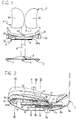
- a chair according to the invention comprises a base 2 with wheels 3 which are orientable in some manner, a telescopically-extendable pillar 4 extending from centre of the base, means not shown since they are wholly conventional for adjusting the height of the pillar 4, a seat, generally indicated 5, supported by the pillar 4 and rotatable relative to the base 2, and a backrest 6 supported by a curved, resiliently yielding arm 7, with marked concavity facing towards the seat 5 with the rear of which it is associated in the manner which will be described further below.
- the seat 5 in turn comprises a substantially box-like frame 8 for supporting a body 9, preferably made of a suitable resiliently-deformable material, for example and preferably, a plastics material such as nylon.
- a pad/squab 10 is associated with the body 9, to which it is fixed in order substantially to form a single body with regard to "movements or displacements" and/or the deformations which the body 9 has to undergo (also limited to its parts) for the desired adjustments of the seat of the invention, as will become clear from the following description.
- the body 9 is controlled by means for adjusting its fore-and-aft inclination to the horizontal.
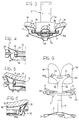
- the body 9 is mounted for pivoting on pins 11, 11 carried by opposite sides 8a, 8b of the box-like frame 8 and defining a horizontal articulation axis (with reference to the chair 1 in its condition of use), transverse the body.
- a shaft 12 parallel to the articulation axis of the body is supported for rotating by the sides 8a, 8b of the frame 8 and two pinions 13, 13 are keyed to the shaft 12. These pinions 13, 13 are in engagement with respective racks 14, 15 slidable in guides 16, 17 fixed to or otherwise formed in the frame 8 and extending perpendicular to the shaft 12.
- Respective vertical supports 18, 19 are fixed to the front portions of the racks and a respective idle wheel (or roller) 20, 21 is associated with the top of each support 18, 19 with its axis parallel to the articulation axis 11-11.
- the wall of the body 9 facing the frame 8 defines, at the front, two straight ramps 22, 23 inclined downwardly towards the front of the body.
- Each ramp 22, 23 is intended to be engaged by a corresponding idle wheel 20, 21 for which it constitutes essentially a straight cam profile.
- the racks 14 and 15 and the wheels 20, 21 fixed thereto can be moved to and fro along the respective guides 16, 17 in the two directions towards the front and towards the rear of the seat 5.
- the racks 14, 15 may be fixed to the frame 8 and the pinions 13, 13 and the shaft 12 to which they are keyed may be free to translate.
- the shaft 12 will again be supported for rotation by the frame 8 with the formation of slit-like slots in the opposite sides 8a, 8b of the frame to allow the shaft 12 and the pinions 13-13 associated therewith to perform the desired rectilinear movements in opposite directions.
- the idle wheels 20-21 (or rollers) in this case are fixed for rectilinear movement with the pinions 13-13.
- the body 9 and the squab 10 are formed with an accentuated transverse concavity ( Figure 1) so as to achieve a marked "wrap-around” effect with consequent considerable lateral restraint.
- the body 9 is controlled by means for gradually varying its transverse concavity.
- a shaft 25a supported for rotation by opposite sides 8a, 8b of the frame 8 extends beneath the front portion of the body 9.
- Two threaded portions 26, 27 with right-hand and left-hand threads formed on the shaft 25a in the region of the parts 9a, 9b of the front portion are engaged by respective threaded sleeves (or nuts) 28, 29 ( Figure 7).
- a corresponding wedge 30, 31 fixed to each of the said sleeves 28, 29 extends transversely relative to the body 9 and has an upper active profile extending transversely relative to the body; the active profile matches and is engaged with the profile of the respective part 9a, 9b of the front body portion.
- the wedges 30, 31 are moved towards one another or apart, that is, towards and away from the centre of the front body portion.
- the parts 9a, 9b of the body are gradually raised with a consequent increase in the transverse concavity of the front portion.
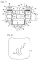
- a U-shaped slot 34 with sides extending towards the front of the seat is formed ( Figure 8) in the central rear region of the squab/pad 10 where, statistically, the bony "projections" of the user's pelvis and coccyx are supported.
- the slot 34 also affects the underlying body 9 ( Figure 3).
- this slot 34 substantially reduces the amount of pressure which is normally exerted on the aforesaid bony projections when chairs of the prior art are in use. This reduction results in a delay in the onset of a condition of restlessness (and often discomfort) which always arises when a fixed position is maintained for too long.
- the presence of the slot 34 considerably improves ventilation in a region of the body which, as is well known, is characterized by the highest skin temperatures.
- a further advantage of the slot 34 is of a static nature, since the lateral portions of the user's buttocks and thighs are "loaded", and a widened support base characterized by reduced pressure and in particular by an absence of excessive pressure peaks is created in these portions.
- the arm 7 supporting the backrest 6 is preferably constituted by a resiliently-deformable metal strip which, in accordance with a non-limiting embodiment, comprises an arcuate central portion 7a with marked concavity, extended by a straight portion 7b and, at the other end, by a branched, Y-shaped end portion forming two identical wings 7c, 7d.
- the straight portion 7b ( Figure 2) is engaged for sliding in an essentially sheath-like guide 35 defined in the frame 8 beneath the body 9 and extending longitudinally relative to the seat 5.
- Means are provided for positioning the portion 7b adjustably along the respective guide 35 so that the backrest 6 can be moved away from or towards the seat 5 at will.
- These means are wholly conventional and comprise, for example, one (or more) pins 36 fixed to the straight portion 7b and a plurality of holes 37 formed in the guide 35 and aligned along it at a predetermined pitch.
- a grip 38 is provided for moving the backrest 6 along the axis defined by the guide 35 and is fixed to the arm 7, for example, in the region in which it branches into the two wings 7c, 7d ( Figure 9).
- the backrest 6 is constituted by two identical, independent portions 39, 40 actuated independently by identical mechanisms so that they can be adapted to the user's back in the manner described below.
- Each of the portions 39, 40 and the respective actuating mechanism are mounted on a respective wing 7c, 7d of the support 7, as will become clear from the following description relating to only one of them.
- each wing 7c (7d) supports for rotation a shaft 41 to which a pinion 42 and an operating knob 43 (43a) are keyed in the front portion and in the rear portion of the backrest 6, respectively.
- Two identical idle gears 44, 45 supported by the same wing 7c (7d) mesh with the pinion 42.
- the idle gears 44, 45 have respective eccentric pins 46, 47 (crank pins) which extend from the same side and the axes of which, in a preferred but not exclusive embodiment, lie in the same horizontal plane.
- the backrest portion 39, 40 in question is fixed to the eccentric pins 46, 47 and follows all of their movements (like a connecting rod).
- each portion 39, 40 of the backrest 6 is constituted by two plate-like elements 39a, 39b ( Figure 11) connected to one another by means of a universal joint 48 (or ball joint or equivalent system), the element 39a being associated with the eccentric pins 46, 47, and the element 39b being intended to "cling" to the user's back.
Landscapes
- Health & Medical Sciences (AREA)
- Dentistry (AREA)
- General Health & Medical Sciences (AREA)
- Chair Legs, Seat Parts, And Backrests (AREA)
- Chairs Characterized By Structure (AREA)
- Chairs For Special Purposes, Such As Reclining Chairs (AREA)
Abstract
Description
- to achieve movement on wheels,
- to rotate the seat/backrest unit relative to the base,
- to adjust the height of the seat/backrest unit,
- to adjust the distance between the seat and the backrest regardless of the backrest position,
- to adjust the inclination of the seat to the horizontal,
- to adjust the height of a front portion of the seat (support for the backs of the knees),
- to adjust the degree of wrap-around/lateral restraint
of the seat, and
regardless of the position and of the "state" of the seat - to identify for the portions of the backrest, each independently of the other, the most suitable spatial arrangement for supporting the user's back, and
- to achieve better lateral restraint and support of the user's vertebral column at the lumbar level.
Claims (16)
- A chair structure comprising a seat (5) and a backrest (6), characterized in that it comprises adjustment means associated with the seat and with the backrest for adjustably varying the orientation of the seat and of the backrest independently of one another according to the desired conditions of support.
- A chair structure according to Claim 1, in which the seat (5) comprises a frame (8) for supporting a body (9) articulated to the frame in the region of a side thereof extending close to the backrest (6) with an articulation axis (11-11) transverse the body (9), and the adjustment means comprise cam means (20-23) between the frame and the body for moving the body (9) angularly about the articulation axis (11-11).
- A chair structure according to Claim 2, in which the cam means comprise at least one ramp (22, 23) on the body extending transversely relative to the articulation axis, at least one ramp-follower element (20, 21) supported on the frame (8) in contact with the respective ramp, and means for driving the ramp-follower element relative to the frame in order to move the ramp-follower element (20, 21) along and in contact with the respective ramp (22, 23) so as to bring about a consequent angular movement of the body about the articulation axis (11-11).
- A chair structure according to Claim 3, in which there are two ramps (22, 23) parallel to one another and spaced apart and the ramp-follower element comprises, for each ramp, a respective idle wheel (20, 21) rotatable about an axis parallel to the articulation axis (11-11).
- A chair structure according to Claim 3 or Claim 4, in which the drive means comprise at least one rack-and-pinion set (13-15) supported by the frame (8) and having one element fixed to the frame and one element movable relative thereto, the cam-follower elements being supported by the movable element of the rack-and-pinion set.
- A chair structure according to Claim 5, in which each ramp-follower element (20, 21) is supported by a respective rack (14, 15) of the rack-and-pinion set, the rack (14, 15) being guided for sliding on the frame (8) along an axis substantially perpendicular to the articulation axis (11-11) and parallel to the corresponding ramp (22, 23).
- A chair structure according to Claim 1, in which the body (9) comprises a slot (24a) extending from an opposite side thereof to the backrest (6) in a central longitudinal position, the slot (24a) defining, in a front portion of the body having transverse concavity relative to the major axis of the slot, two parts (9a, 9b) controlled by means for varying the said concavity.
- A chair structure according to Claim 7, in which the means for varying the concavity of the front parts (9a, 9b) of the body (9) comprise an inclined-plane device interposed between the frame (8) and the body (9).
- A chair structure according to Claim 8, in which the inclined-plane device comprises a pair of wedge-shaped elements (30, 31) slidable on the frame, relative to the respective parts (9a, 9b) of the body (9), along an axis substantially perpendicular to the major axis of the slot (24a), the wedge-shaped elements and the body having coupling surfaces with planes inclined in the direction of sliding.
- A chair structure according to Claim 9, in which the inclined-plane device comprises male-and-female threaded means (26-28, 27-29) associated with the wedge-shaped elements for bringing about rectilinear movement of the wedge-shaped elements towards and away from the slot (24a), the inclination selected for the surfaces with inclined planes being such that the concavity of the body portion defined by the parts (9a, 9b) is increased by a movement of the wedge-shaped elements towards the slot (24a).
- A chair structure according to Claim 1, comprising, on the body (9), a cover/squab (10) through a rear central region of which a slot (34) extends.
- A chair structure according to Claim 11, in which the slot (34) is U-shaped with sides extending towards the front of the seat (5).
- A chair structure according to Claims 11 and 12, in which a further slot extends through the body (9) in a substantially superimposed arrangement with the U-shaped slot in the cover-squab (10).
- A chair structure according to Claim 1, in which the backrest (6) comprises two identical, independent portions (39, 40) supported by respective wings (7c, 7d) formed by a support arm (7a) of the backrest (6), and the adjustment means comprise actuator means for moving the portions independently relative to one another so that the portions can be adapted independently of one another to different portions of the user's back.
- A chair structure according to Claim 14, in which the actuator means comprise, for each respective portion (39,40), a pinion (42) supported for rotating by a respective wing (7c, 7d) and in engagement with a pair of idle gears (44, 45) supported for rotation by the wing (7c, 7d), the gears having respective eccentric pins (46, 47) engaged in the corresponding portions (39, 40) of the backrest (6).
- A chair structure according to Claim 15, in which each of the portions (39, 40) of the backrest (6) comprises a first plate-shaped element (39a) associated with the corresponding eccentric pins (46, 47) and a second plate-shaped element (39b) connected to the first plate-shaped element (39a) by means of a universal joint (48), the second plate-shaped element (39b) being intended to cling to the user's back.
Applications Claiming Priority (2)
| Application Number | Priority Date | Filing Date | Title |
|---|---|---|---|
| ITPD960301 | 1996-12-06 | ||
| IT96PD000301 IT1288007B1 (en) | 1996-12-06 | 1996-12-06 | CHAIR STRUCTURE |
Publications (2)
| Publication Number | Publication Date |
|---|---|
| EP0846429A2 true EP0846429A2 (en) | 1998-06-10 |
| EP0846429A3 EP0846429A3 (en) | 2000-05-17 |
Family
ID=11391595
Family Applications (1)
| Application Number | Title | Priority Date | Filing Date |
|---|---|---|---|
| EP97203375A Withdrawn EP0846429A3 (en) | 1996-12-06 | 1997-10-30 | A chair structure |
Country Status (2)
| Country | Link |
|---|---|
| EP (1) | EP0846429A3 (en) |
| IT (1) | IT1288007B1 (en) |
Cited By (4)
| Publication number | Priority date | Publication date | Assignee | Title |
|---|---|---|---|---|
| RU2206295C1 (en) * | 2002-02-14 | 2003-06-20 | Быков Алексей Алексеевич | Method for unloading vertebral column |
| WO2011005231A1 (en) * | 2009-07-06 | 2011-01-13 | Burosit Buro Donanimlari Sanayi Ve Ticaret Anonim Sirketi | Sitting apparatus providing body ergonomy |
| CN109124132A (en) * | 2018-09-19 | 2019-01-04 | 宁波市玄图数字科技有限公司 | Office seating regulating device |
| CN119055480A (en) * | 2024-10-31 | 2024-12-03 | 佛山市思福特医疗设备有限公司 | Dental chair |
Family Cites Families (11)
| Publication number | Priority date | Publication date | Assignee | Title |
|---|---|---|---|---|
| US3463547A (en) * | 1967-10-20 | 1969-08-26 | John M Brennan | Flexible chair seat |
| DE7731339U1 (en) * | 1977-10-11 | 1978-01-26 | Fa. Willibald Grammer, 8450 Amberg | VEHICLE SEAT |
| JPS5849864Y2 (en) * | 1979-07-26 | 1983-11-14 | トヨタ自動車株式会社 | Seat cushion inclination angle adjustment device |
| US4479679A (en) * | 1981-06-08 | 1984-10-30 | Steelcase Inc. | Body weight chair control |
| DE3130999A1 (en) * | 1981-08-05 | 1983-02-24 | Sitag Sitzmöbel AG, 9430 St. Margrethen | WORK CHAIR WITH ADJUSTABLE SEAT AND BACKREST |
| IT1219314B (en) * | 1988-05-18 | 1990-05-03 | Pro Cord Srl | CHAIR WITH OSCILLATING SEAT |
| WO1990000873A1 (en) * | 1988-07-19 | 1990-02-08 | 'aura' Herbert D. Stolle Gmbh & Co. | Back-rest |
| DE9006316U1 (en) * | 1990-06-05 | 1990-08-16 | "Aura" Herbert D. Stolle GmbH & Co, 2000 Hamburg | backrest |
| ES2060507B1 (en) * | 1991-06-25 | 1997-04-16 | Normalien Srl | SUITABLE DEVICES FOR THE INCLINATION OF THE BACK AND SEAT OF CHAIRS AND ARMCHAIRS. |
| US5580128A (en) * | 1994-08-10 | 1996-12-03 | Johnson; Robert E. | Therapeutic seat |
| NL1001159C1 (en) * | 1995-09-08 | 1997-03-11 | Everwijn Petrus Maria Ridder | Chair or armchair. |
-
1996
- 1996-12-06 IT IT96PD000301 patent/IT1288007B1/en active IP Right Grant
-
1997
- 1997-10-30 EP EP97203375A patent/EP0846429A3/en not_active Withdrawn
Cited By (6)
| Publication number | Priority date | Publication date | Assignee | Title |
|---|---|---|---|---|
| RU2206295C1 (en) * | 2002-02-14 | 2003-06-20 | Быков Алексей Алексеевич | Method for unloading vertebral column |
| WO2003068114A1 (en) * | 2002-02-14 | 2003-08-21 | Alexei Alexeevich Bykov | Method for relieving the backbone |
| WO2011005231A1 (en) * | 2009-07-06 | 2011-01-13 | Burosit Buro Donanimlari Sanayi Ve Ticaret Anonim Sirketi | Sitting apparatus providing body ergonomy |
| CN109124132A (en) * | 2018-09-19 | 2019-01-04 | 宁波市玄图数字科技有限公司 | Office seating regulating device |
| CN109124132B (en) * | 2018-09-19 | 2021-06-08 | 宁波市玄图数字科技有限公司 | Office Seat Adjuster |
| CN119055480A (en) * | 2024-10-31 | 2024-12-03 | 佛山市思福特医疗设备有限公司 | Dental chair |
Also Published As
| Publication number | Publication date |
|---|---|
| EP0846429A3 (en) | 2000-05-17 |
| ITPD960301A1 (en) | 1998-06-06 |
| IT1288007B1 (en) | 1998-09-10 |
Similar Documents
| Publication | Publication Date | Title |
|---|---|---|
| US7669928B2 (en) | Adjustable thigh support for automobile seat via adjustment plate | |
| US6193313B1 (en) | Chair | |
| US5582459A (en) | Chair having tiltable seat back | |
| US5120109A (en) | Motor vehicle seat | |
| US5487591A (en) | Back shell with selective stiffening | |
| US6454353B1 (en) | Chair, in particular work chair | |
| US5704689A (en) | Chair having separable back | |
| US6213553B1 (en) | Seat element | |
| US20060152053A1 (en) | Seat apparatus having variable gap | |
| DE3930983A1 (en) | SEAT FURNITURE WITH TILT ADJUSTABLE SEAT | |
| KR960031199A (en) | Devices for adjusting the pressure distribution in the backrest of a vehicle chair | |
| US7354107B2 (en) | Vehicle seat with a deformable S-shaped backrest | |
| EP0846429A2 (en) | A chair structure | |
| EP0957721B1 (en) | Chair | |
| DE9416674U1 (en) | Seating and training area | |
| CA2041669A1 (en) | Adjustable seating assembly | |
| JP4838452B2 (en) | Tilting chair | |
| KR100708303B1 (en) | Chair with adjustable back | |
| KR20100059407A (en) | Chair | |
| GB2287649A (en) | Seat or support device for fork-lift truck operators | |
| EP0672370B1 (en) | Chair having an assisted scissor mechanism | |
| EP1579787A1 (en) | Chair having automatic back inclination adjustment | |
| JPH11253268A (en) | Automobile seat | |
| JPH0542772Y2 (en) | ||
| EP1306033A2 (en) | Chair |
Legal Events
| Date | Code | Title | Description |
|---|---|---|---|
| PUAI | Public reference made under article 153(3) epc to a published international application that has entered the european phase |
Free format text: ORIGINAL CODE: 0009012 |
|
| AK | Designated contracting states |
Kind code of ref document: A2 Designated state(s): AT BE CH DE DK ES FR GB IT LI NL PT SE |
|
| PUAL | Search report despatched |
Free format text: ORIGINAL CODE: 0009013 |
|
| AK | Designated contracting states |
Kind code of ref document: A3 Designated state(s): AT BE CH DE DK ES FI FR GB GR IE IT LI LU MC NL PT SE |
|
| 17P | Request for examination filed |
Effective date: 20000615 |
|
| AKX | Designation fees paid |
Free format text: AT BE CH DE DK ES FR GB IT LI NL PT SE |
|
| 17Q | First examination report despatched |
Effective date: 20020517 |
|
| STAA | Information on the status of an ep patent application or granted ep patent |
Free format text: STATUS: THE APPLICATION IS DEEMED TO BE WITHDRAWN |
|
| 18D | Application deemed to be withdrawn |
Effective date: 20030731 |