EP0845360B1 - Capping unit and ink-jet recording apparatus using the same - Google Patents
Capping unit and ink-jet recording apparatus using the same Download PDFInfo
- Publication number
- EP0845360B1 EP0845360B1 EP97120956A EP97120956A EP0845360B1 EP 0845360 B1 EP0845360 B1 EP 0845360B1 EP 97120956 A EP97120956 A EP 97120956A EP 97120956 A EP97120956 A EP 97120956A EP 0845360 B1 EP0845360 B1 EP 0845360B1
- Authority
- EP
- European Patent Office
- Prior art keywords
- capping unit
- holder
- cap
- recording head
- capping
- Prior art date
- Legal status (The legal status is an assumption and is not a legal conclusion. Google has not performed a legal analysis and makes no representation as to the accuracy of the status listed.)
- Expired - Lifetime
Links
Images


Classifications
-
- B—PERFORMING OPERATIONS; TRANSPORTING
- B41—PRINTING; LINING MACHINES; TYPEWRITERS; STAMPS
- B41J—TYPEWRITERS; SELECTIVE PRINTING MECHANISMS, i.e. MECHANISMS PRINTING OTHERWISE THAN FROM A FORME; CORRECTION OF TYPOGRAPHICAL ERRORS
- B41J2/00—Typewriters or selective printing mechanisms characterised by the printing or marking process for which they are designed
- B41J2/005—Typewriters or selective printing mechanisms characterised by the printing or marking process for which they are designed characterised by bringing liquid or particles selectively into contact with a printing material
- B41J2/01—Ink jet
- B41J2/135—Nozzles
- B41J2/165—Preventing or detecting of nozzle clogging, e.g. cleaning, capping or moistening for nozzles
- B41J2/16505—Caps, spittoons or covers for cleaning or preventing drying out
- B41J2/16508—Caps, spittoons or covers for cleaning or preventing drying out connected with the printer frame
- B41J2/16511—Constructions for cap positioning
-
- B—PERFORMING OPERATIONS; TRANSPORTING
- B41—PRINTING; LINING MACHINES; TYPEWRITERS; STAMPS
- B41J—TYPEWRITERS; SELECTIVE PRINTING MECHANISMS, i.e. MECHANISMS PRINTING OTHERWISE THAN FROM A FORME; CORRECTION OF TYPOGRAPHICAL ERRORS
- B41J2/00—Typewriters or selective printing mechanisms characterised by the printing or marking process for which they are designed
- B41J2/005—Typewriters or selective printing mechanisms characterised by the printing or marking process for which they are designed characterised by bringing liquid or particles selectively into contact with a printing material
- B41J2/01—Ink jet
- B41J2/135—Nozzles
- B41J2/165—Preventing or detecting of nozzle clogging, e.g. cleaning, capping or moistening for nozzles
- B41J2/16517—Cleaning of print head nozzles
- B41J2/16535—Cleaning of print head nozzles using wiping constructions
- B41J2/16544—Constructions for the positioning of wipers
- B41J2/16547—Constructions for the positioning of wipers the wipers and caps or spittoons being on the same movable support
Definitions
- This invention relates to a capping unit suitable for use in a recording apparatus having an ink-jet recording head which is moved in the width direction of a recording sheet, and forms images on the recording sheet or the like by jetting ink droplets according to print data.
- An ink-jet recording apparatus records print data on a recording sheet or the like by jetting ink droplets from nozzle openings while ink is pressurized in pressure generating chambers.
- an ink-jet recording apparatus has potential inconveniences resulting in poor printing quality due to an increase in ink viscosity caused by the evaporation of an ink solvent from the nozzle openings, the solidified ink and dust sticking to the nozzle openings and the penetration of air bubbles therethrough. Therefore, the ink-jet recording apparatus is normally provided with a capping means for sealing up the nozzle openings of a recording head during the non-printing operation and a cleaning means for cleaning a nozzle plate, if necessary.
- a capping unit having a cap which is pressed by a recording head or a carriage for carrying the recording head to move between a non-capping position and a capping position, the capping unit being placed outside a printing area, a cam face and a cam follower for moving the cap to the side of a nozzle plate of the recording head while the recording head is kept moving from the non-capping position to the capping position.
- the carriage is only moved whereby to ensure that it is brought into resilient contact with and seals up the nozzle plate.
- the number of nozzle openings of a black recording head for jetting black ink in order to meet high-density, high-speed printing requirements and the number of nozzle openings of a color recording head for jetting three kinds of colored ink tend to increase.
- the size in the paper feeding direction and the size in the width direction of paper grow larger, the size of the cap for sealing up each recording head becomes inevitably larger and the inconvenience is that the sealing capability is lowered.
- the ink penetrated between the cap and the recording head is set up because of the use of quick-drying ink and the like, thus causing the cap to rigidly stick to the recording head, and this develops the problem of necessitating a strong force of separating the cap therefrom.
- a tube pump is employed for a pump unit for filling the recording head with ink and supplying negative pressure to the cap at the time of cleaning in view of cost and reliability and besides part of the tube used to form the pump is directly used as a connection channel with the cap. Therefore, there still exists another problem resulting from great repulsive force of the tube, which acts as what impedes the adhesion of the cap, thus reducing the adhesion thereof because such a tube has to be placed in a limited space and is made of relatively rigid material so as to resist against the pressure applied by a roller while functioning as a pump tube.
- EP-A-653 306 discloses a cap urged by one spring.
- the present invention provides a capping unit as defined in claim 1 and an ink jet recording apparatus as defined in claim 61 respectively.
- a capping unit as defined in claim 1
- an ink jet recording apparatus as defined in claim 61 respectively.
- a capping unit is equipped with a holder receiving member which is pressed by a recording head or a carriage for carrying the recording head and whose central portion is rotatably supported by a shaft perpendicularly intersecting the moving direction of the carriage within a plane in parallel to a plane including the moving direction of the carriage; a first and a second holder each of which is urged toward the recording head by a spring which is brought into contact with the holder receiving member at two places in the moving direction of the carriage and supported by the holder receiving member with one point on the center line on one end side as a contact point and with two points holding the center line therebetween as contact points, the distance of the one point from the surface of the recording head on the side where the two points are supported is set greater than the distance of the other two points therefrom; and a first and a second cap respectively held by the first and second holders.
- the cap holders are supported at three points with respect to the holder supporting member and since there is a difference of the distance to the whole periphery of the cap for the recording head, the moment generated then lets a peeling-off operation start from one point and this causes the load to be decreased.
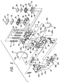
- FIG. 1 shows an embodiment of the present invention, wherein a carriage 1 is connected via a timing belt 2 to a motor 3 and adapted to move in parallel to a platen 5 by guidance of a guide member 4.
- An ink-jet recording head 7 for jetting black ink and an ink-jet recording head 8 for jetting color ink are installed on the opposite-to-recording-paper-6 side of the carriage 1, and the recording heads 7, 8 operate to print characters and patterns on recording sheet 6 on receiving supplies of ink from the respective ink cartridges 9, 10.
- a capping unit 11 is provided with caps 12, 13 of such a size as is large enough to seal up the nozzle openings of the recording heads 7, 8 in sealing spaces independent of each other, and functions as what seals up the nozzle plates of the recording heads 7, 8 at the time of non-printing in order to prevent ink in a nozzle opening orifice from drying up and what forces ink out of the recording heads 7, 8 on receiving negative pressure from a pump unit 14 when the jet capability is recovered.
- a wiping blade 15 made of elastic material such as rubber and used for removing ink and ink dregs by resiliently contacting the recording heads 7, 8 is installed so that it is movable back and forth on the moving loci of the recording heads 7, 8.
- a slider 20 follows the movement of the carriage 1 and is moved on the surface of a base 30 in a non-printing direction and on the recording head side, that is, in the vertical direction according to this embodiment of the present invention.
- the slider 20 has a contact piece 21 formed in the end portion on the non-printing area side and is supported with the first guide surface 31 of the base 30, one end of the slider 20 being supported by the other end of an arm 50 rotatably mounted on the base 30 on the front end side from the center (the right-hand side of FIG.
- the slider 20 is secured to the other end of a tension spring 51 whose one end is secured to the base 30 above the contact piece 21 and always urged in the direction of the printing area and in the direction in which it is separated from the recording heads 7, 8, that is, urged downward according to this embodiment of the present invention.
- a cap holder receiving member 40 is used for accommodating a first and a second cap holder 60, 70 and its shaft 41 is placed in the central portion, preferably in a position where the moments of compression springs 61, 62 for urging the cap holder 60 and those of compression springs 71, 72 for urging the cap holder 70 are balanced.
- the shaft 41 is rotatably supported by a receiving portion 22 provided in a front end portion on the printing area side of the slider 20 and also always urged by a tension spring 53 stretched to the slider 20 on the printing area side toward the rear end side (the left-hand side of FIG. 2(a) or right-hand side of FIG. 2(b)), that is, in the direction of the non-printing area and in the direction in which it is separated from the recording heads 7, 8, that is, urged downward according to this embodiment of the present invention.
- the first and second cap holders 60, 70 are accommodated in the cap holder receiving member 40 in such a state that it is always urged by the compression springs 61, 62 and 71, 72 separately fitted in the bottoms of the cap holders at two places in the longitudinal direction on the substantially center line of the cap holder receiving member 40 toward the recording head, that is, urged upward according to this embodiment of the present invention.
- Caps 65, 75 for containing a first and a second ink absorbing sheet 63, 64 and 73, 74, each being formed of a plurality of sheets of porous material, two sheets thereof according to this embodiment of the present invention, are fitted in the respective cap holders 60, 70.
- the first and second ink absorbing sheets 63, 64 and 73, 74 are such that those placed closer to the recording heads 7, 8 have larger diameter pores, and are arranged so that a different in capillary force is utilized for moving ink from the surface to the bottom.
- the base 30 has the first guide surface 31 on its rear end side and the second guide surface 32 on its front end side. There are formed three areas on the first guide surface 31; namely, a low place portion 31a on its front end side, a horizontal high place portion 31b on its rear end side and a slope portion 31c for connecting the former two portions 31a, 31b. Further, there are formed three areas on the second guide surface 32; namely, a low place portion 32a on its front end side, a horizontal high place portion 32b on its rear end side and a slope portion 32c for connecting the former two portions 32a, 32b. As shown in FIG.
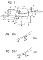
- the ascent quantity ⁇ H1 caused by the second guide surface 32 is set greater than the ascent quantity ⁇ H2 caused by the first guide surface 31, and an angle ⁇ with respect to the horizontal plane of the slope portion 31c of the first guide surface 31 is set smaller than an angle ⁇ connecting the support shaft 28 of the slider 20 and the contact piece 21.
- the resistance R generated when the slider 20 ascends along the slope portion 31c includes, as shown in FIG. 5(A), the upward-directed component R1 of the slope portion 31c.
- the cap holder receiving member 40 has a contact piece 42 to be guided by the second guide surface 32, the contact piece 42 being formed in the lower portion of the front end side. Further, guide pieces 43, 43 and 44, 44 which are brought into contact with the sides of the recording heads 7, 8 in order to guide the caps 65, 75 to predetermined positions are provided in the side portions of the cap holder receiving member 40, respectively.
- a separate or integral ink-splash shielding plate 45 so position as not to touch the recording heads 7, 8 but to be as wide as the print height of the recording heads 7, 8 is provided on the front edge face situated opposite to the wiping blade 15.
- the ink-splash shielding plate 45 is preferably formed of a polymer material or the like having ink absorbing properties.
- the slider 20 is formed with a flag piece 27 at its rear end, the flag piece being brought into contact with the side wall of the recording head 8 or the carriage 1 and pressed thereby according to this embodiment of the present invention.
- a valve seat 25 having two holes 23, 24 is fixed via a holder 26 on the rear side of the side portion of the slider 20.
- the slider 20 As the slider 20 is moved close to the marginal point in the rear end portion, on the other hand, it faces a valve 33 always urged by springs 34, 34 fitted in guide shafts 33a, 33a toward the front end side, the valve being installed on the base 30 and horizontally movable back and forth in a position opposite to the valve seat.
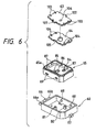
- the first cap holder 60 is formed with a T-shaped slip stop portion 66 on the center line on one side in the moving direction of the carriage 1 and an I-shaped slip stop portion 67 on the other side therein.
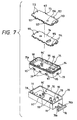
- the second cap holder 70 is formed with a T-shaped slip stop portion 76 on one side in the moving direction of the carriage 1 in such a manner as to pass the center line and an I-shaped slip stop portion 77 on the other side therein.
- These T-shaped slip stop portions 66, 76 have branch pieces 66a, 66b and 76a, 76b extending in a direction perpendicular to the moving direction of the carriage 1, respectively.
- the surfaces of the branch pieces 66a, 76a on one side are formed so that the surfaces thereof facing the recording heads are set closer to the recording heads than the other branch pieces 66b, 76b, that is, set higher than the latter according to this embodiment of the present invention.
- cap holders 60, 70 While the cap holders 60, 70 are being urged by the aforementioned springs 61, 62 and 71, 72 upward, they are accommodated in the cap holder receiving member 40 and held therein by pivotally engaging the upper ends of these slip stop portions 66, 67 and 76, 77 with the respective recesses of the cap holder receiving member 40.
- the rear sides of the cap holders are slightly expansively opened by ⁇ 1, ⁇ 2 with respect to the recording heads 7, 8, and as shown in Fig. 8(b), the cap holders are accommodated in the cap holder receiving member 40 in such a state that one end side of each cap holder is expansively opened by an angle of ⁇ 3 in the width direction.
- the springs 61, 62 and 71, 72 used to urge these cap holders 60, 70 are, as shown in FIGs. 9(a), 9(b), selected so that their external shapes D1, D2 cover at least 1/3 of the width W1, W2 of the short sides of the cap holders 60, 70.
- the springs 61, 62 and 71, 72 are arranged in that they are positioned on the respective end sides of the long sides of the cap holders 60, 70. Further, these springs 61, 62 and 71, 72 are preferably positioned inward from or across a triangular area (the area shown by hatching in FIG. 9) connection points where the slip stop portions 66, 67 and 76, 77 are brought into contact with the cap holder receiving member 40.
- the caps 65, 75 Since one end sides of the caps 65, 75 are tilted by the angles ⁇ 1, ⁇ 2, ⁇ 3 with respect to the planes of the recording heads 7, 8 so that the one end sides thereof are expansively opened as described above, the balance of the force of bringing the caps 65, 75 contact with the recording heads 7, 8 is lacking, that is, the gaps with respect to the recording heads 7, 8 tend to become varied. Therefore, as shown in FIGs 10(a), 10(b), the springs 62, 72 positioned in areas P1, P2 where the contact force is weakened are offset toward the areas P1, P2 by ⁇ S1, ⁇ S2 from the center line, and springs 62, 72 having greater resiliently pressing force are preferably employed.
- the first cap holder 60 has in its bottom portion the retaining member of the cap 65, the pump unit 14 and two cylindrical bodies 80, 81 simultaneously used as connection pipes with the valve seat 25.
- the cylindrical body 80 is, as shown in FIG. 12, used to connect a pump connection 100 integral therewith to the pump unit 14 via a tube 54, whereas the cylindrical body 81 is used to connect an air-communicating-port connection 100 to the opening 23 of the valve seat 25 via a tube 55.
- the cylindrical body 70 has in its bottom portion the retaining member of the cap 75, the pump unit 14 and two cylindrical bodies 90, 91 simultaneously used as connection pipes with the valve seat 25.
- the cylindrical body 90 is, as shown in FIG. 13, used to connect a pump connection 110 integral therewith to the pump unit 14 via a tube 56, whereas the cylindrical body 91 is used to connect an air-communicating-port connection 111 to the opening 24 of the valve seat 25 via a tube 57.
- FIG. 14 shows connecting relations between the pump unit 14 and the cap holders 60, 70, wherein the pump unit 14 is in a double strand of pump tubes according to this embodiment of the present invention, one ends of the tubes 54, 56 being drawn to suction port sides so as to form connection pipes.
- the tubes 54, 56 are, as shown in FIG. 15, led out in such a manner that it remains parallel to a plane perpendicular to what include the moving direction of the carriage 1 via a guide 14a, and tilted by an angle ⁇ .
- the tube is made of relatively rigid material because it has to be placed in a limited space, functions as a pump tube and has also to resist against the pressure applied by a roller.
- the great repulsive force of the tubes 54, 56 results in giving a moment to the cap holders 60, 70 in the direction of an arrow A of FIG. 15.
- This moment needless to say acts on the caps 65, 75 and the recording heads 7, 8 in such a way as to impair the adhesion therebetween.
- the tubes 54, 56 are, as shown in FIG. 16, twisted so that they are so postured as to be parallel to a plane including the moving direction of the carriage 1 by means of their individual resiliency.
- the twisting of this sort is, as shown in FIG. 14(a), given in the same direction mutually or, as shown in FIG. 14(b), in directions opposite to each other.
- the tubes 54, 56 are thus forcibly directed to the horizontal direction in order to prevent the generation of a moment which impairs the adhesive force without impairing the motion of the slider 20 and to decrease the height of the whole apparatus.
- one end 55a of the tube 55 connected to the first cap holder 60 separated from the valve 25 is connected to a connection port 26a formed in a direction parallel to the moving direction of the slider 20 from the side wall of the holder 26; the body area 55b thereof is secured to the side of the slider 20; and the other end 55c thereof is fitted in the connection 101 of the cylindrical body 81 formed vertically on the bottom of the holder 60.
- One end of the tube 57 connected to the second holder 70 position near the valve 25 is connected to a connection port 26b formed in a direction perpendicular to the moving direction of the carriage 1 from the side wall of the holder 26; the tube 57 is curved in substantially parallel to a plane perpendicular to the moving direction of the slider 20 so as to form a curved portion 57b; and the other end 57b thereof is fitted in the connection 111 of the cylindrical body 91 formed vertically on the bottom of the holder 70.
- a plurality of pawls 68, 68 are formed on the inner peripheral face of the first cap holder 60. Further, recesses 69, 69 engaging with the pawl 68 are formed in the outer peripheral side face of the cap 65, and through-holes 84, 85 engaging with the aforementioned cylindrical bodies 80, 81 are formed in the bottom thereof, these engaging with one another to have the cap 65 held by the holder 60.
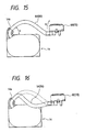
- the front of an ink absorbing plate 46 is, as shown in FIGs. 17(a), 17(b), disposed in contact with a thin-wall portion 102 for forming the sealing surface of the cap 65 on the opposite side of the wiping blade 15. The ink absorbing plate 46 is folded into the bottom of the holder 60 and clamped by the holder 60 and the cap 65.
- a plurality of pawls 78, 78 are formed on the inner peripheral face of the cap holder 70. Further, recesses 79, 79 engaging with the pawl 78 are formed in the outer peripheral side face of the cap 75, and through-holes 94, 95 and 94', 95' engaging with the cylindrical bodies 90, 91 and dummy cylindrical bodies 90', 91' are formed in the bottom thereof, these mutually engaging with one another to have the cap 75 held by the holder 70. Further, the cap 75 is installed so that receiving portions 93, 93 for holding rivets for use in surely holding the ink absorbing sheets 73, 74 are formed in order that the rivets 92, 92 are fixed in a position not facing a nozzle opening orifice N2. Further, the dummy cylindrical bodies 90', 91' are formed in a position symmetrical with the cylindrical bodies 90, 91.
- the thin-wall portion 102 of the cap 65 is formed whose rigidity is lower than that of any other portion in order for its open face to function as a sealing portion; thus, an ink repellent process is provided. Further, a plurality of pawls 87, 87 for retaining the surface of the upper-layer ink absorbing sheet 63 is formed closer to the bottom side from the thin-wall portion. A recess 86 communicating with the cylindrical body 81 is formed in the bottom.
- the pawl 87 of the cap 65 and the pawl 98 of the cap 75 press down the ink absorbing sheets 63, 64 and the ink absorbing sheets 73, 74 against their resiliency toward the bottom side in order to prevent them from floating up whereby to earn the distance between the recording heads 7, 8 and the ink absorbing sheets 63, 73 by decreasing the depth of the caps 65, 75 as much as possible. While an attempt is made to make compact the caps 65, 75, the ink forced to be discharged from the recording heads 7, 8 can thus be prevented from splashing back to the recording heads 7, 8 .
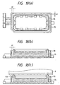
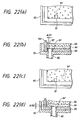
- gaps al, b1 wide enough to maintain the sealing condition and to absorb the expansion of the cap 75 are formed with respect to the cap 70 as shown in FIGs. 18(a), 18(b).
- the gap b1 on the long side which is comparatively less rigid is set smaller than the gap al on the short side.
- the gap b1 on the long side is, as shown in FIGs. 19(a), preferably formed with wide protrusions 70a, 70a protruding toward the cap side in the central area of the cap holder receiving member 70 or convex portions 70b, 70b as shown in FIGs.
- the protrusion 70a and the convex portion 70b for regulating the gap has obviously the same effect even though they are formed on the outer peripheral side of the cap 75.
- the caps 65, 75 are prevented from slipping off the holder 60, 70 even though the caps 65, 75 are stuck to the surface of the recording heads 7, 8 due to dried ink as the caps are brought into resilient contact with the holders 60, 70 due to distortion resulting from some amount of elastic deformation while the acting force applied when the caps 65, 75 are opened is absorbed by the resiliency of the caps 65, 75.
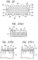
- the ink absorbing sheets 63, 64 and 73, 74 accommodated in the respective caps 65, 75 are provided with measures to prevent the ink absorbing sheets from stripping off because of swelling by providing a small number of relatively large through-holes 103, 104 and 113, 114 in a position where the common ink absorbing function is not specifically impaired, uniformly forming a number of very small through-holes 121 over the whole sheet as shown in FIG. 20, or providing cutouts in the corner portion to which the swelled volume is shifted so as to make the through-holes 103, 104, 113, 114, 121 or the cutouts 123, 123 absorb what is equivalent to the swelled volume.
- a relatively large through-hole 105 communicating with the recess 86 of the cap 65 is bored in the ink absorbing sheet 64 accommodated in the lower layer of the cap 65, whereas a relatively small through-hole 106 is bored in the ink absorbing sheet 63 accommodated in the upper layer thereof in such a position that the through-hole 106 is not made opposite to the through-hole 85. Further, these through-holes 105, 106 are, as shown FIG.
- the ink absorbing sheets 63, 73 disposed in the uppermost layers are formed with tongue pieces 107, 107,... and 117, 117, 117, 117,...
- the front end 117a is, as shown in FIG. 21(a), brought into contact with the proximity of the lower portion of the thin-wall portion 112 of the cap 75, and the side face 117b of the tongue piece 117 is, as shown in FIG. 21(b), brought into contact with the side face of the pawl 98 of the cap 75.
- tongue pieces 122, 122, 122,... are, as shown in FIG. 20, formed opposite to one another at the respective four corners of the caps 60, 70, so that the tongue piece 122 is desirably used to guide ink which tends to accumulate at the corners of the thin-wall portions 102, 112 of the caps 60, 70. Further, it is desired to form these tongue pieces 107, 117, 122 in positions not opposite to the nozzle opening orifices N1, N2 at the time of flushing and capping the recording heads 7, 8.
- a through-hole 84'' communicating with the pump unit 14 When a through-hole 84'' communicating with the pump unit 14 is formed in a position set away from the wall of the cap 65 or the pawl 87 as shown in FIGs, 22(c), 22(d), on the contrary, there is produced a gap ⁇ G2 between the through-hole 84'' and the ink absorbing sheets 63, 64 because of the floating-up of the ink absorbing sheets 63, 64 resulting from swelling and the like, and such idle suction is also caused. Therefore, at least the through-holes 84, 94 communicating with the pump unit 14 are preferably formed in the proximity of the pawls 87, 98 of the caps 65, 75 and separated by at least about the diameters of the through-holes 84, 94 from the respective walls of the caps.
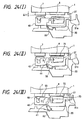
- the cap holder receiving member 40 is then positioned in parallel to the recording heads 7, 8 by the high place portions 31b, 32b of the first and second guide surfaces 31, 32 to ensure that the recording heads 7, 8 are sealed up by the caps 65, 75 even though there exists a slight difference ⁇ H in level between the surfaces of the two recording heads 7, 8 (FIG. 24(III)).
- the cap holder receiving member 40 is thus positioned in parallel to the planes of the recording heads 7, 8 to ensure that the recording heads 7, 8 are sealed up when a variable component ⁇ P occurs in the platen gap in accordance with the thickness of recording paper as shown in FIG. 25(a), that is, even when the recording heads 7, 8 are displaced relatively to the caps 65, 75.
- a gap ⁇ N is produced in the sealing surface between the recording heads 7, 8 due to variations in the fitting precision of the two recording heads 7, 8 to the carriage 1
- the cap holder receiving member 40 is rotated by an angle of ⁇ so that the counter force received from the recording heads 7, 8 on both sides of the shaft 41 this time is balanced as shown in FIG.
- the posture of the cap holder receiving member 40 is adjusted to become parallel to the planes of the recording heads 7, 8 before the caps 65, 75 are brought into contact with the recording heads 7, 8 according to this embodiment of the present invention, it is possible to reduce the load of the slider 20 by letting the cap holder receiving member 40 positively assume a non-parallel posture, that is, bringing the cap holder receiving member 40 into contact with one of the recording heads 7, 8 in a tilted condition by making the heights of the high place portions 31b, 32b of the slopes of the first and second guide surfaces 31, 32 different from each other. Even in this case, the cap holder receiving member 40 is made to rotate with respect to the slider 20 in order to bring ultimately the caps 65, 75 into resilient contact with the recording heads 7, 8.
- caps 65, 75 urged upward by the springs 61, 62 and 71, 72 respectively arrange in front and in the rear side immediately before they are brought into contact with the recording heads 7, 8 are, as shown in FIG. 8, slightly tilted with the rear end side as the lower side and one end side in the width direction as the lower side, whereby shock at the time of capping is eased since the thin wall portions 102, 112 are brought into contact with the recording heads 7, 8 while gradually increasing their contact areas from the one ends of their front end sides.
- the valve seat 25 is, as shown in FIG. 26, brought into resilient contact with the valve 33 installed on the base 30, and the caps 65, 75 are caused to cut off communication with the air and put in an airtight condition.
- the evaporation ink from the nozzle opening orifices N1, N2 is suppressed with the effect of preventing the nozzle from being clogged with ink. Since the tubes 54, 56 having relatively high rigidity as described above are made to have the habit of paralleling a plane including the moving directions of the recording heads 7, 8, the force of peeling the caps 65, 75 off the recording heads 7, 8 does not act on the caps 65, 75.
- the tubes 55, 57 connected to the valve seat 25 are vertically connected to the cap holders 60, 70, further, the force of peeling the caps 65, 75 off the recording heads 7, 8 does not also act on the caps 65, 75. Moreover, the force deriving from the tubes 54, 56 in the horizontal direction is received by the cap holder receiving member 40 and the sealing-up strength is not impeded accordingly.
- the pump unit 14 When the nozzle opening orifices N1, N2 of the recording heads 7, 8 are clogged or when ink is forced out of the recording heads 7, 8 because of replacement of cartridges, on the other hand, the pump unit 14 is operated in the above-described capping state.
- the negative pressure from the pump unit 14 caused negative pressure to act on the insides of the caps 65, 75 via the holes 84, 94 of the caps 65, 75, whereby ink is sucked out of the nozzle opening orifices N1, N2.
- dust and fine powder sticking to the proximity of the nozzle opening orifices N1, N2 are cleaned and bubbles in the recording heads 7, 8 together with ink are discharged into the caps 65, 75.
- the ink discharged from the recording heads 7, 8 is absorbed by the upper-layer ink absorbing sheets 63, 73 before being absorbed by the lower-layer ink absorbing sheets 64, 74 having finer pores by capillary force.
- the absorbing power is made improvable by decreasing the impregnated ink quantity in the upper-layer ink absorbing sheets 63, 73 as much as possible; ink is prevented from sticking to the recording heads 7, 8; and the splashing of ink is reduced when ink is forced to be discharged.
- the ink When ink is thus forced to be discharged, the ink tends to accumulate in the proximity of the thin-wall portions 102, 112 of the caps 65, 75 and at the pawls 87, 98 due to the splashing and spattering of ink from the ink absorbing sheets 63, 73.
- the ink never stays at such spots as these spots are kept in contact with the tongue pieces 107, 117 used to absorb the ink, whereby the ink is prevented from uselessly sticking to the nozzle plates of the recording heads.
- the provision of a suction port 130 and an air-communicating port 131 across a nozzle opening orifice N allows ink bubbles B, B,... generated when the air is introduced to cross the nozzle opening orifice N and the meniscus of the nozzle opening orifice N is destroyed.
- the pawls 87, 98 for resiliently pressing the upper ink absorbing sheets 63, 73 positioned in the proximity of the cylindrical bodies 80, 90 at least communicating with the pump unit 14 are formed in the caps 65, 75 in which the ink absorbing sheets 73, 74 are accommodated.
- the through-holes 84, 94 are also covered with the ink absorbing sheets 63, 64 and 73, 74 to ensure that ink is sucked without idle suction.
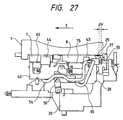
- the carriage 1 When the operation of forcing ink to be discharged from the recording heads 7, 8 is completed, the carriage 1 is, as shown in FIG. 27, moved by a small amount ⁇ V in the front end direction (in the direction of an arrow E in the drawing) in order to make the through-holes 85, 95 of the caps 65, 75 communicate with the air by separating the valve seat 25 from the valve 33.
- the rear end side of the slider 20 slides on the slope portion 31c of the base 30 by means of the contact piece 21 and the front end side is guided by the slope portion 32c of the base 30 by means of the contact piece 42 of the cap holder receiving member 40 and then lowered along the central portion while supported by the rotation of the lever 50.
- the caps 65, 75 urged upward by the springs 61, 62 and 71, 72 respectively arrange in front and in the rear side are made to slightly tilt with the rear end side as the lower side and one end side in the width direction as the lower side.
- the caps 65, 75 While the height and pressure contact force of the front end sides and the rear end sides of the caps 65, 75 are balanced by means of the rotation of the cap holder receiving member 40 around the central shaft 41, the thin-wall portions 102, 112 as sealing surfaces are made to follow the recording heads 7, 8 by the use of the swinging of the holders 60, 70 supported at three places of protrusions 66, 67 and 76, 77. Thus, the caps 65, 75 are separated from the surfaces of the recording heads 7, 8 while gradually increasing the contact areas from their rear end sides to one ends.
- the ink K (FIG. 33(I)) stuck in such a manner as to cover the whole open face of the cap 65 is uniformly extended to form the film K1 of the size which is able to seal up the whole open face of the cap 65 (FIG. 33(II)).
- a film K2' is extended in the direction in which the cap is separated by following the movement of the cap (FIG. 33(III)).
- the ink film K2' ultimately bursts and the splashed ink K3' sticks over the whole surface of the recording head 87 to the thin wall portion 102 of the cap 65 (FIG. 33(IV)).
- the splashed ink K3' affects the wetting properties of ink in the nozzle opening orifice N1, thus inducing printing quality to lower.
- a small amount of ink is splashed in the aforementioned restricted area when the cap 65 is peeled off and in order that in the case of a color recording head 8 as shown in FIG. 29(a), color which does not affect printing with splashed ink, that is, the yellow (Y) nozzle opening orifice N2 is used or otherwise the nozzle opening orifice N2 is preferably placed apart by relatively increasing its length by a small amount ⁇ W up to the position which no splashed ink reaches as shown in FIG. 29(b). In the case where its length is increased like this, no restriction will be imposed on the color nozzle opening orifice.
- the blade 15 When the nozzle opening is cleaned as it is clogged with ink, the blade 15 is moved forward within the moving locus of the recording head 8 and then the carriage 1 is moved to the printing area side (FIG. 30(I)). The blade 15 is subjected to elastic deformation and brought into resilient contact with the surface of the moving second recording head 8 (FIG. 30(II)), whereby ink and ink dregs sticking thereto are wiped away.
- the blade 15 bounds back without the support of the recording head 8 and part of the wiped ink in the form of splashes K is allowed to splash in the direction of the cap 65. However, the splashed ink is blocked by the ink-splash shielding plate 45 (FIG.
- tubes may be used to make the dummy through-holes 90', 91' respectively communicate with the pump unit 14 and the hole 24 of the valve seat 25 in the case of a especially large-sized cap 75, and through-holes 115', 116' also corresponding to the ink absorbing sheets 73, 74 are bored to ensure that waste ink in the ink absorbing sheets 73, 74 is discharged, irrespective of the size of the cap.
Description
- This invention relates to a capping unit suitable for use in a recording apparatus having an ink-jet recording head which is moved in the width direction of a recording sheet, and forms images on the recording sheet or the like by jetting ink droplets according to print data.
- An ink-jet recording apparatus records print data on a recording sheet or the like by jetting ink droplets from nozzle openings while ink is pressurized in pressure generating chambers. However, such an ink-jet recording apparatus has potential inconveniences resulting in poor printing quality due to an increase in ink viscosity caused by the evaporation of an ink solvent from the nozzle openings, the solidified ink and dust sticking to the nozzle openings and the penetration of air bubbles therethrough. Therefore, the ink-jet recording apparatus is normally provided with a capping means for sealing up the nozzle openings of a recording head during the non-printing operation and a cleaning means for cleaning a nozzle plate, if necessary.
- For example, as disclosed in Unexamined Japanese Patent Publication No. Hei. 6-8460, there has been proposed a capping unit having a cap which is pressed by a recording head or a carriage for carrying the recording head to move between a non-capping position and a capping position, the capping unit being placed outside a printing area, a cam face and a cam follower for moving the cap to the side of a nozzle plate of the recording head while the recording head is kept moving from the non-capping position to the capping position.
- According to the arrangement above, the carriage is only moved whereby to ensure that it is brought into resilient contact with and seals up the nozzle plate. However, the number of nozzle openings of a black recording head for jetting black ink in order to meet high-density, high-speed printing requirements and the number of nozzle openings of a color recording head for jetting three kinds of colored ink tend to increase. As the size in the paper feeding direction and the size in the width direction of paper grow larger, the size of the cap for sealing up each recording head becomes inevitably larger and the inconvenience is that the sealing capability is lowered.
- Moreover, the ink penetrated between the cap and the recording head is set up because of the use of quick-drying ink and the like, thus causing the cap to rigidly stick to the recording head, and this develops the problem of necessitating a strong force of separating the cap therefrom.
- Further, there is another problem arising from a decrease in sealing strength as the sealing surface varies with the head-to-head tolerance and so forth because a platen gap is caused to greatly fluctuate when characters are printed on various printing media.
- There is still another problem developing from the residual ink staying and setting up at the recording head when an attempt is made to form a thin-wall portion on the open face to secure a sealing condition by decreasing the elasticity of the cap in order to solve the problems mentioned above.
- On the other hand, a tube pump is employed for a pump unit for filling the recording head with ink and supplying negative pressure to the cap at the time of cleaning in view of cost and reliability and besides part of the tube used to form the pump is directly used as a connection channel with the cap. Therefore, there still exists another problem resulting from great repulsive force of the tube, which acts as what impedes the adhesion of the cap, thus reducing the adhesion thereof because such a tube has to be placed in a limited space and is made of relatively rigid material so as to resist against the pressure applied by a roller while functioning as a pump tube.
- EP-A-653 306 discloses a cap urged by one spring.
- It is therefore a primary object of the present invention to provide a capping unit capable of ensuring that one or a plurality of recording heads are sealed up and simply peeling off a cap sticking to the recording head.
- It is a second object of the present invention to provide a capping unit capable of ensuring that recording sheet is sealed up and decreasing the clinging of ink to a cap.
- It is a third object of the present invention to provide a ink-jet recording apparatus using such a capping unit as stated above.
- To solve this object the present invention provides a capping unit as defined in
claim 1 and an ink jet recording apparatus as defined inclaim 61 respectively. Preferred embodiments of the invention are described in the subclaims. - The claims are understood as a first non-limiting approach for defining the invention in general terms without restricting the scope thereof.
- A capping unit according to the present invention is equipped with a holder receiving member which is pressed by a recording head or a carriage for carrying the recording head and whose central portion is rotatably supported by a shaft perpendicularly intersecting the moving direction of the carriage within a plane in parallel to a plane including the moving direction of the carriage; a first and a second holder each of which is urged toward the recording head by a spring which is brought into contact with the holder receiving member at two places in the moving direction of the carriage and supported by the holder receiving member with one point on the center line on one end side as a contact point and with two points holding the center line therebetween as contact points, the distance of the one point from the surface of the recording head on the side where the two points are supported is set greater than the distance of the other two points therefrom; and a first and a second cap respectively held by the first and second holders. Thus, the cap holders are supported at three points with respect to the holder supporting member and since there is a difference of the distance to the whole periphery of the cap for the recording head, the moment generated then lets a peeling-off operation start from one point and this causes the load to be decreased.
- Further details, objects and advantages of the invention will be apparent from the following detailed description thereof in conjunction with the drawings, in which:
- FIG. 1 is a perspective view of an ink-jet recording apparatus using a capping unit embodying the present invention;
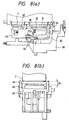
- FIGs. 2(a) and 2(b) are perspective views of the capping unit as viewed from both sides according to the embodiment of the present invention;
- FIG. 3 is a perspective assembly drawing of the capping unit;
- FIG. 4 is a diagram illustrating the relation among the ascending quantity of the capping unit by means of a first and a second guide surface, an angle of the first guide and the angle of the rotary shaft of slider with the first guide surface;
- FIGS. 5(a) and 5(b) are diagrams illustrating the relation of load resistance to the angle of the first guide surface and the angle between the rotary shaft of the slide and the first guide surface;
- FIG. 6 is a perspective assembly drawing of a first cap embodying the present invention;
- FIG. 7 is a perspective assembly drawing of a second cap embodying the present invention;
- FIGs. 8(a) and 8(b) are diagrams showing the inclinations of the respective first and second caps in a direction perpendicular to the moving direction of them and in a direction parallel thereto with respect to a recording head at the time of non-capping;
- FIGs. 9(a) and 9(b) are diagrams showing contact positions of springs for suppressively supporting respective first and second cap holders, and (c) a sectional view showing a state in which the cap holder is supported by the spring;
- FIGs. 10(a) and 10(b) are diagrams showing contact positions of springs for suppressively supporting respective first and second cap holders according to another embodiment of the present invention;
- FIG. 11 is a diagram illustrating the moments of the springs for suppressively supporting the first and second cap holders;
- FIGs. 12(a) and 12(b) are diagrams showing the surface structure of the first cap and a sectional structure taken along a line XII(b) - XII(b), respectively;
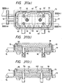
- FIGs. 13(a), 13(b) and 13(c) diagrams showing the surface structure of the second cap, a sectional structure taken along a line XIII(b) - XIII(b) and what is taken along a line XIII(c) - XIII(c), respectively;
- FIGs. 14(a) and 14(b) are top views showing forms of tubes for connecting a pump and a cap holder, respectively;
- FIG. 15 is a side view explanatory of the form of drawing the tube from the pump unit and the force of the tube exerting on the cap holder;
- FIG. 16 is a side view showing the form of the tube for connecting the pump and the cap holder;
- FIGs. 17(a) and 17(b) are a perspective view and an enlarged sectional view showing the cap and the cap holder which are placed on the wiper blade side, respectively;
- FIGS. 18(a), 18(b) and 18(c) are diagrams showing the gap formed between the cap holder and the cap, and the function of the gap, respectively;
- FIGs. 19(a) and 19(b) are top views showing a cap holder according to another embodiment of the present invention, respectively;
- FIG. 20 is a diagram showing an ink absorbing sheet to be placed in the upper layer of a cap according to another embodiment of the present invention;
- FIG. 21(a) is a diagram showing the relation between the tongue piece of the ink absorbing sheet and the thin-wall portion of the cap; and FIGs. 21(b) and 21(c) are diagrams showing the positional relations to respective pawls, respectively;
- FIGs. 22(a) and 22(b) are diagrams illustrating nonconformity arising from the positional relation between a through-hole communicating with the pump unit and the ink absorbing sheet; and FIGs. 22(c) and 22(d) what arises from the positional relation between the pawl and the through-hole, respectively;
- FIG. 23 is a diagram showing a state in which the recording head has been moved to a flushing position;
- FIGs. 24(I) - 24(III) are diagrams showing the motion of the cap holders, respectively;
- FIGs. 25(a) and 25(b) are diagrams illustrating the capping operation accompanied by the alteration of the platen gap and what corresponds to the fitting tolerance of the recording head, respectively;
- FIG. 26 is a diagram showing a state in which the recording head has moved to the capping position;
- FIG. 27 is a diagram showing a state in which the recording head has moved from the capping unit to a position where ink is jetted;
- FIGs. 28(I) - 28(IV) are diagrams illustrating phenomena in which ink is splashed when the caps are releasing by means of the capping units according to the present invention, respectively; .
- FIGs. 29(a) and 29(b) are diagrams showing a nozzle-opening orifice arrangement corresponding to the ink splashes caused at the time of releasing the caps, and a capping unit according to the embodiment of the present invention, respectively;
- FIGs. 30(I) - 30(III) are diagrams showing a cleaning operation to be performed by the capping unit according to the present invention;
- FIGs. 31(a), 31(b) and 31(c) are diagrams showing the surface structure of the second cap, a sectional structure taken along a line XXXI(b) - XXXI(b) and what is taken on line XXXI(c) - XXXI(c), respectively;
- FIGs. 32(a) and 32(b) are diagrams showing the ink bubbles produced by the ink absorbing sheets in the conventional cap, respectively; and
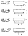
- FIGs. 33(I) - 33(IV) are diagrams illustrating phenomena of ink splashing generated when a cap is released in a conventional capping unit.
-
- A detailed description will subsequently be given of embodiments of the present invention with reference to the accompanying drawings.
- FIG. 1 shows an embodiment of the present invention, wherein a
carriage 1 is connected via atiming belt 2 to amotor 3 and adapted to move in parallel to aplaten 5 by guidance of aguide member 4. An ink-jet recording head 7 for jetting black ink and an ink-jet recording head 8 for jetting color ink are installed on the opposite-to-recording-paper-6 side of thecarriage 1, and therecording heads recording sheet 6 on receiving supplies of ink from therespective ink cartridges - A
capping unit 11 is provided withcaps recording heads recording heads recording heads pump unit 14 when the jet capability is recovered. Awiping blade 15 made of elastic material such as rubber and used for removing ink and ink dregs by resiliently contacting therecording heads recording heads - Referring to FIGs. 2(a), 2(b) and FIG. 3, there is given a schematic description of the
capping unit 11 as embodied in the present invention. When thecarriage 1 moves from a printing area to a non-printing area, aslider 20 follows the movement of thecarriage 1 and is moved on the surface of abase 30 in a non-printing direction and on the recording head side, that is, in the vertical direction according to this embodiment of the present invention. Theslider 20 has acontact piece 21 formed in the end portion on the non-printing area side and is supported with thefirst guide surface 31 of thebase 30, one end of theslider 20 being supported by the other end of anarm 50 rotatably mounted on thebase 30 on the front end side from the center (the right-hand side of FIG. 2(a) or left-hand side of FIG. 2(b)). Theslider 20 is secured to the other end of atension spring 51 whose one end is secured to thebase 30 above thecontact piece 21 and always urged in the direction of the printing area and in the direction in which it is separated from the recording heads 7, 8, that is, urged downward according to this embodiment of the present invention. - A cap
holder receiving member 40 is used for accommodating a first and asecond cap holder shaft 41 is placed in the central portion, preferably in a position where the moments of compression springs 61, 62 for urging thecap holder 60 and those of compression springs 71, 72 for urging thecap holder 70 are balanced. Theshaft 41 is rotatably supported by a receivingportion 22 provided in a front end portion on the printing area side of theslider 20 and also always urged by atension spring 53 stretched to theslider 20 on the printing area side toward the rear end side (the left-hand side of FIG. 2(a) or right-hand side of FIG. 2(b)), that is, in the direction of the non-printing area and in the direction in which it is separated from the recording heads 7, 8, that is, urged downward according to this embodiment of the present invention. - The first and
second cap holders holder receiving member 40 in such a state that it is always urged by the compression springs 61, 62 and 71, 72 separately fitted in the bottoms of the cap holders at two places in the longitudinal direction on the substantially center line of the capholder receiving member 40 toward the recording head, that is, urged upward according to this embodiment of the present invention. -
Caps ink absorbing sheet respective cap holders ink absorbing sheets - A further description will be given of each member. The
base 30 has thefirst guide surface 31 on its rear end side and thesecond guide surface 32 on its front end side. There are formed three areas on thefirst guide surface 31; namely, alow place portion 31a on its front end side, a horizontalhigh place portion 31b on its rear end side and aslope portion 31c for connecting the former twoportions second guide surface 32; namely, alow place portion 32a on its front end side, a horizontalhigh place portion 32b on its rear end side and aslope portion 32c for connecting the former twoportions second guide surface 32 is set greater than the ascent quantity ΔH2 caused by thefirst guide surface 31, and an angle α with respect to the horizontal plane of theslope portion 31c of thefirst guide surface 31 is set smaller than an angle β connecting thesupport shaft 28 of theslider 20 and thecontact piece 21. Thus, the resistance R generated when theslider 20 ascends along theslope portion 31c includes, as shown in FIG. 5(A), the upward-directed component R1 of theslope portion 31c. When the angle α with respect to the horizontal plane of theslope portion 31c of thefirst guide surface 31 conversely becomes greater than the angle β connecting thesupport shaft 28 of theslider 20 and thecontact piece 21, the load resistance of thecarriage 1 for moving theslider 20 tends to become greater since the resistance R includes, as shown in FIG. 5(B), the downward-directed component R3 of theslope portion 31c. - On the other hand, the cap
holder receiving member 40 has acontact piece 42 to be guided by thesecond guide surface 32, thecontact piece 42 being formed in the lower portion of the front end side. Further, guidepieces caps holder receiving member 40, respectively. A separate or integral ink-splash shielding plate 45 so position as not to touch the recording heads 7, 8 but to be as wide as the print height of the recording heads 7, 8 is provided on the front edge face situated opposite to thewiping blade 15. The ink-splash shielding plate 45 is preferably formed of a polymer material or the like having ink absorbing properties. - The
slider 20 is formed with aflag piece 27 at its rear end, the flag piece being brought into contact with the side wall of therecording head 8 or thecarriage 1 and pressed thereby according to this embodiment of the present invention. Avalve seat 25 having twoholes 23, 24 is fixed via aholder 26 on the rear side of the side portion of theslider 20. As theslider 20 is moved close to the marginal point in the rear end portion, on the other hand, it faces avalve 33 always urged bysprings guide shafts base 30 and horizontally movable back and forth in a position opposite to the valve seat. - As shown in FIG. 6, the
first cap holder 60 is formed with a T-shapedslip stop portion 66 on the center line on one side in the moving direction of thecarriage 1 and an I-shapedslip stop portion 67 on the other side therein. As shown in Fig. 7, further, thesecond cap holder 70 is formed with a T-shapedslip stop portion 76 on one side in the moving direction of thecarriage 1 in such a manner as to pass the center line and an I-shapedslip stop portion 77 on the other side therein. These T-shapedslip stop portions branch pieces carriage 1, respectively. The surfaces of thebranch pieces other branch pieces - While the
cap holders aforementioned springs holder receiving member 40 and held therein by pivotally engaging the upper ends of these slip stopportions holder receiving member 40. Thus, as shown in FIG. 8(a), the rear sides of the cap holders are slightly expansively opened by 1, 2 with respect to the recording heads 7, 8, and as shown in Fig. 8(b), the cap holders are accommodated in the capholder receiving member 40 in such a state that one end side of each cap holder is expansively opened by an angle of 3 in the width direction. - The
springs cap holders cap holders - Consequently, to take an example from the
cap holder 60, even if the slightly tilted cap holder is brought into contact with therecording head 7 as shown in FIG. 9(c), it maintains a posture in which it is capable of sealing up therecording head 7 by means of thespring 61 itself. As shown in FIGs. 9(a), 9(b), thesprings cap holders springs slip stop portions holder receiving member 40. - Since one end sides of the
caps caps springs springs cap holder 60 and the force F21, F22 of thesprings cap holder 70 are so selected as to make the moment M1 = (F11 x L11 + F12 x L12) and the moment M2 = (F21 x L21 + F22 x L22) acted on theshaft 41 substantially equal (FIG. 11). - The
first cap holder 60 has in its bottom portion the retaining member of thecap 65, thepump unit 14 and twocylindrical bodies valve seat 25. Thecylindrical body 80 is, as shown in FIG. 12, used to connect apump connection 100 integral therewith to thepump unit 14 via atube 54, whereas thecylindrical body 81 is used to connect an air-communicating-port connection 100 to theopening 23 of thevalve seat 25 via atube 55. Thecylindrical body 70 has in its bottom portion the retaining member of thecap 75, thepump unit 14 and twocylindrical bodies valve seat 25. Thecylindrical body 90 is, as shown in FIG. 13, used to connect apump connection 110 integral therewith to thepump unit 14 via atube 56, whereas thecylindrical body 91 is used to connect an air-communicating-port connection 111 to the opening 24 of thevalve seat 25 via atube 57. - FIG. 14 shows connecting relations between the
pump unit 14 and thecap holders pump unit 14 is in a double strand of pump tubes according to this embodiment of the present invention, one ends of thetubes pump unit 14, thetubes carriage 1 via aguide 14a, and tilted by an angle τ. Further, the tube is made of relatively rigid material because it has to be placed in a limited space, functions as a pump tube and has also to resist against the pressure applied by a roller. Therefore, the great repulsive force of thetubes cap holders caps - In order to ease this problem, the
tubes carriage 1 by means of their individual resiliency. The twisting of this sort is, as shown in FIG. 14(a), given in the same direction mutually or, as shown in FIG. 14(b), in directions opposite to each other. Thetubes slider 20 and to decrease the height of the whole apparatus. - Of the tubes connected to the
valve 25, on the other hand, oneend 55a of thetube 55 connected to thefirst cap holder 60 separated from thevalve 25 is connected to aconnection port 26a formed in a direction parallel to the moving direction of theslider 20 from the side wall of theholder 26; thebody area 55b thereof is secured to the side of theslider 20; and theother end 55c thereof is fitted in theconnection 101 of thecylindrical body 81 formed vertically on the bottom of theholder 60. One end of thetube 57 connected to thesecond holder 70 position near thevalve 25 is connected to aconnection port 26b formed in a direction perpendicular to the moving direction of thecarriage 1 from the side wall of theholder 26; thetube 57 is curved in substantially parallel to a plane perpendicular to the moving direction of theslider 20 so as to form acurved portion 57b; and theother end 57b thereof is fitted in theconnection 111 of thecylindrical body 91 formed vertically on the bottom of theholder 70. - A plurality of
pawls first cap holder 60. Further, recesses 69, 69 engaging with thepawl 68 are formed in the outer peripheral side face of thecap 65, and through-holes cylindrical bodies cap 65 held by theholder 60. The front of anink absorbing plate 46 is, as shown in FIGs. 17(a), 17(b), disposed in contact with a thin-wall portion 102 for forming the sealing surface of thecap 65 on the opposite side of thewiping blade 15. Theink absorbing plate 46 is folded into the bottom of theholder 60 and clamped by theholder 60 and thecap 65. - A plurality of
pawls cap holder 70. Further, recesses 79, 79 engaging with thepawl 78 are formed in the outer peripheral side face of thecap 75, and through-holes cylindrical bodies cylindrical bodies 90', 91' are formed in the bottom thereof, these mutually engaging with one another to have thecap 75 held by theholder 70. Further, thecap 75 is installed so that receivingportions ink absorbing sheets rivets cylindrical bodies 90', 91' are formed in a position symmetrical with thecylindrical bodies - The thin-
wall portion 102 of thecap 65 is formed whose rigidity is lower than that of any other portion in order for its open face to function as a sealing portion; thus, an ink repellent process is provided. Further, a plurality ofpawls ink absorbing sheet 63 is formed closer to the bottom side from the thin-wall portion. Arecess 86 communicating with thecylindrical body 81 is formed in the bottom. - The
pawl 87 of thecap 65 and thepawl 98 of thecap 75 press down theink absorbing sheets ink absorbing sheets ink absorbing sheets caps caps - To take an example from the
second cap holder 70 representing both the first andsecond cap holders cap 75 are formed with respect to thecap 70 as shown in FIGs. 18(a), 18(b). The gap b1 on the long side which is comparatively less rigid is set smaller than the gap al on the short side. The gap b1 on the long side is, as shown in FIGs. 19(a), preferably formed withwide protrusions holder receiving member 70 orconvex portions wall portion 112 of thewhole cap 70 by suppressing the gaps b2, b3, which readily tend to bend, in the central area of the long side. Further, theprotrusion 70a and theconvex portion 70b for regulating the gap has obviously the same effect even though they are formed on the outer peripheral side of thecap 75. By securing a proper gap of 0.2 - 1.0 mm, preferably a gap of about 0.4 mm in a case where rubber hardness ranges from 50 to 60° between theholders caps caps - Further, by securing a certain degree of rigidity and resiliency for the
caps caps holder caps holders caps caps - The
ink absorbing sheets respective caps holes holes 121 over the whole sheet as shown in FIG. 20, or providing cutouts in the corner portion to which the swelled volume is shifted so as to make the through-holes cutouts - A relatively large through-
hole 105 communicating with therecess 86 of thecap 65 is bored in theink absorbing sheet 64 accommodated in the lower layer of thecap 65, whereas a relatively small through-hole 106 is bored in theink absorbing sheet 63 accommodated in the upper layer thereof in such a position that the through-hole 106 is not made opposite to the through-hole 85. Further, these through-holes cylindrical body 80 does not cross the nozzle opening orifice N1. - Of the plurality of ink absorbing sheets accommodated in the
caps ink absorbing sheets tongue pieces ink absorbing sheet 73, thefront end 117a is, as shown in FIG. 21(a), brought into contact with the proximity of the lower portion of the thin-wall portion 112 of thecap 75, and theside face 117b of thetongue piece 117 is, as shown in FIG. 21(b), brought into contact with the side face of thepawl 98 of thecap 75. To take an example from theink absorbing sheet 73, both side faces 117b of thetongue piece 117... are, as shown in FIG. 21(c), brought into resilient contact with the respective twopawls pawls tongue pieces caps tongue piece 122 is desirably used to guide ink which tends to accumulate at the corners of the thin-wall portions caps tongue pieces - In order to ensure that negative pressure from the
pump unit 14 is made to act on theink absorbing sheets respective caps holes pump unit 14 and thepawls cap 65, even though theink absorbing sheets cap 65 when a through-hole 84' communicating with thepump unit 14 is formed near the side wall of thecap 65, there is produced a gap ΔG1 as the whole through-hole 84' is not covered with thepump unit 14 and idle suction is caused. When a through-hole 84'' communicating with thepump unit 14 is formed in a position set away from the wall of thecap 65 or thepawl 87 as shown in FIGs, 22(c), 22(d), on the contrary, there is produced a gap ΔG2 between the through-hole 84'' and theink absorbing sheets ink absorbing sheets holes pump unit 14 are preferably formed in the proximity of thepawls caps holes - A description will subsequently be given of the apparatus thus constructed.
- While the
slider 20 is unmoved even when thecarriage 1 is, as shown in FIG. 23, moved in the non-printing direction (the direction shown by an arrow D therein) and brought into contact with theflag piece 27 of theslider 20, the first andsecond caps ink absorbing sheets respective caps - When the
carriage 1 is moved to the rear end side (to the right in the drawing) further (FIG. 24(II)), theslider 20 is caused to move in the oblique direction while rotating thearm 50 against the tensile strength of thetension spring 51. Simultaneously, the capholder receiving member 40 rotates in the direction of an arrow B in the drawing around theshaft 41 whose central portion is supported by theslider 20, whereby thecap 75 is brought into contact with the recording head 8 (FIG. 24 (II)). When thecarriage 1 is moved further, since thecontact piece 42 is guided to theslope portion 32c of the base, the front end side of the capholder receiving member 40 is reversed in the direction of an arrow C in FIG. 24(II) so as to correct its posture to what is substantially parallel to the recording heads 7, 8 and move together with theslider 20 toward the recording head side. The capholder receiving member 40 is then positioned in parallel to the recording heads 7, 8 by thehigh place portions caps recording heads 7, 8 (FIG. 24(III)). - The cap
holder receiving member 40 is thus positioned in parallel to the planes of the recording heads 7, 8 to ensure that the recording heads 7, 8 are sealed up when a variable component ΔP occurs in the platen gap in accordance with the thickness of recording paper as shown in FIG. 25(a), that is, even when the recording heads 7, 8 are displaced relatively to thecaps recording heads carriage 1, the capholder receiving member 40 is rotated by an angle of η so that the counter force received from the recording heads 7, 8 on both sides of theshaft 41 this time is balanced as shown in FIG. 25b, whereby the spring force of thesprings caps caps - Although the posture of the cap
holder receiving member 40 is adjusted to become parallel to the planes of the recording heads 7, 8 before thecaps slider 20 by letting the capholder receiving member 40 positively assume a non-parallel posture, that is, bringing the capholder receiving member 40 into contact with one of the recording heads 7, 8 in a tilted condition by making the heights of thehigh place portions holder receiving member 40 is made to rotate with respect to theslider 20 in order to bring ultimately thecaps caps springs thin wall portions - In this stage wherein the
caps valve seat 25 is, as shown in FIG. 26, brought into resilient contact with thevalve 33 installed on thebase 30, and thecaps tubes caps caps tubes valve seat 25 are vertically connected to thecap holders caps caps tubes holder receiving member 40 and the sealing-up strength is not impeded accordingly. - When the nozzle opening orifices N1, N2 of the recording heads 7, 8 are clogged or when ink is forced out of the recording heads 7, 8 because of replacement of cartridges, on the other hand, the
pump unit 14 is operated in the above-described capping state. The negative pressure from thepump unit 14 caused negative pressure to act on the insides of thecaps holes caps caps - The ink discharged from the recording heads 7, 8 is absorbed by the upper-layer
ink absorbing sheets ink absorbing sheets ink absorbing sheets wall portions caps pawls ink absorbing sheets tongue pieces - As shown in FIG. 32, on the other hand, the provision of a
suction port 130 and an air-communicatingport 131 across a nozzle opening orifice N allows ink bubbles B, B,... generated when the air is introduced to cross the nozzle opening orifice N and the meniscus of the nozzle opening orifice N is destroyed. Further, thepawls ink absorbing sheets cylindrical bodies pump unit 14 are formed in thecaps ink absorbing sheets holes ink absorbing sheets - When the operation of forcing ink to be discharged from the recording heads 7, 8 is completed, the
carriage 1 is, as shown in FIG. 27, moved by a small amount ΔV in the front end direction (in the direction of an arrow E in the drawing) in order to make the through-holes caps valve seat 25 from thevalve 33. When thepump unit 14 is subsequently operated, negative pressure acting on thecaps holes holes 23, 24 of thevalve seat 25 and also causes ink staying in theink absorbing sheets caps holes pump unit 14 and discharged outside without making useless negative pressure acting on the nozzle opening orifices N1, N2 of the recording heads 7, 8. When the operation of discharging waste ink in thecaps pump unit 14 is stopped and the recording heads 7, 8 are moved to the printing area. During this process of moving the recording heads 7, 8, the rear end side of theslider 20 slides on theslope portion 31c of the base 30 by means of thecontact piece 21 and the front end side is guided by theslope portion 32c of the base 30 by means of thecontact piece 42 of the capholder receiving member 40 and then lowered along the central portion while supported by the rotation of thelever 50. During the process of lowering theslider 20, thecaps springs caps holder receiving member 40 around thecentral shaft 41, the thin-wall portions holders protrusions caps - Since the recording heads 7, 8 are released from the
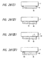
caps caps caps caps recording head 7 and thethin wall portion 102 of the cap as the ink is forced to be discharged, and ink K (FIG. 28(I)) stuck in a such a state as to cover the whole open face of the cap 65 (FIG. 28(8)) causes a film K1 to be formed (FIG. 28(II)). Consequently, ink splashes K1 are produced as they slightly burst as the gap in an area where therecording head 7 is initially separated from thecap 65 grows larger and most of the remaining ink K3 is directed (in the direction of an arrow F) to an area wherein the capillary force is greater and another area where the gap between thecap 65 and therecording head 7 is small (FIG. 28(III)). Consequently, the ink is accumulated into ink drops K4 at one point of the end portion where thecaps - When the open face of the
cap 65 is separated in parallel to the plane of therecording head 7, on the contrary, the ink K (FIG. 33(I)) stuck in such a manner as to cover the whole open face of thecap 65 is uniformly extended to form the film K1 of the size which is able to seal up the whole open face of the cap 65 (FIG. 33(II)). When thecap 65 is moved away from therecording 7, further, a film K2' is extended in the direction in which the cap is separated by following the movement of the cap (FIG. 33(III)). The ink film K2' ultimately bursts and the splashed ink K3' sticks over the whole surface of therecording head 87 to thethin wall portion 102 of the cap 65 (FIG. 33(IV)). The splashed ink K3' affects the wetting properties of ink in the nozzle opening orifice N1, thus inducing printing quality to lower. - A small amount of ink is splashed in the aforementioned restricted area when the
cap 65 is peeled off and in order that in the case of acolor recording head 8 as shown in FIG. 29(a), color which does not affect printing with splashed ink, that is, the yellow (Y) nozzle opening orifice N2 is used or otherwise the nozzle opening orifice N2 is preferably placed apart by relatively increasing its length by a small amount ΔW up to the position which no splashed ink reaches as shown in FIG. 29(b). In the case where its length is increased like this, no restriction will be imposed on the color nozzle opening orifice. - When the nozzle opening is cleaned as it is clogged with ink, the
blade 15 is moved forward within the moving locus of therecording head 8 and then thecarriage 1 is moved to the printing area side (FIG. 30(I)). Theblade 15 is subjected to elastic deformation and brought into resilient contact with the surface of the moving second recording head 8 (FIG. 30(II)), whereby ink and ink dregs sticking thereto are wiped away. When therecording head 8 passes therethrough, theblade 15 bounds back without the support of therecording head 8 and part of the wiped ink in the form of splashes K is allowed to splash in the direction of thecap 65. However, the splashed ink is blocked by the ink-splash shielding plate 45 (FIG. 30(III)) and ink sticking to thethin wall portion 102 of thecap 65 is absorbed by the ink absorbing plate 46 (FIG. 17). Thus, ink splashes resulting from the cleaning operation are prevented from being solidified between thecap 60 and the recording head to ensure that it does not become unpeelable. - Although the pair of through-
holes pump unit 14 and the pair of through-holes caps holes 90', 91' respectively communicate with thepump unit 14 and the hole 24 of thevalve seat 25 in the case of a especially large-sized cap 75, and through-holes 115', 116' also corresponding to theink absorbing sheets ink absorbing sheets
Claims (61)
- A capping unit for capping a surface of a recording head (7, 8), the recording head (7, 8) being carried by a carriage (1) along a moving direction, said capping unit comprising:characterised in thata holder receiving member (40) which is pressable by the recording head (7, 8) or by the carriage (1) to perform a movement, wherein a central portion of said holder receiving member (40) is rotatably supported by a shaft (41) perpendicular to the moving direction of the carriage (1); anda first and a second cap (65, 75) held by first and second holders (60, 70) accommodated in said holder receiving member (40), said holders (60, 70) having center lines oriented in the moving direction,
said first and second caps (65, 75) are urged towards the recording head (7, 8) by a first pair (61, 62) and a second pair of springs (71, 72) in contact with said holder receiving member (40), wherein each of said pairs of springs (61, 62, 71, 72) is brought into contact with said holder receiving member (40) at two places spaced apart in the moving direction of the carriage (1). - The capping unit as claimed in claim 1, wherein said shaft (41) is provided in a position where moments (M1, M2) of said springs (61, 62, 71, 72) for urging said first and second holders (60, 70) are balanced.
- The capping unit as claimed in claim 1 or 2, wherein said springs (61, 62, 71, 72) are positioned on said center lines of said holders (60, 70) and so disposed as to be brought into contact with the proximity of both ends of the holder (60, 70).
- The capping unit as claimed in any one of claims 1 to 3, wherein:said holders (60, 70) are supported at first, second and third contact points by said holder receiving member (40) with said first contact point being arranged on one end of said respective holder (60, 70) on said center line, and with said second and/or said third contact point being arranged on the other end of said respective holder (60, 70), said second and third contact points holding said center line inbetween, andwherein said springs (61, 62, 71, 72) are so disposed as to be within an area connecting said first, second and third contact points.
- The capping unit as claimed in any one of claims 1 to 4, wherein a diameter (D1, D2) of said springs (61, 62, 71, 72) is not smaller than 1/3 of the side-to-side width (W1, W2) of said holder (60, 70).
- The capping unit according to claim 1, wherein:said holders (60, 70) are supported at first, second and third contact points by said holder receiving member (40) with said first contact point being arranged on one end of said respective holder (60, 70) on said center line, and with said second and/or said third contact point being arranged on the other end of said respective holder (60, 70), said second and third contact points holding said center line inbetween; andwherein a distance of said third contact point from the surface of the recording head (7, 8) is set greater than a distance of said first and second contact points therefrom.
- The capping unit as claimed in claim 6, wherein said spring (61, 62, 71, 72) disposed on an end of said holder (60, 70) where said distance from the recording head (7, 8) becomes greater is offset from said center line of said holder (60, 70) towards the side where said distance becomes greater.
- The capping unit as claimed in one of claims 6 or 7, wherein said spring (61, 62, 71, 72) disposed on an end where said distance from the recording head (7, 8) becomes greater is set so that a spring force of said spring (61, 62, 71, 72) is greater than a spring force of said spring (61, 62, 71, 72) disposed on the other end.
- The capping unit as claimed in any one of claims 6 to 8, wherein a distance between an edge portion of said cap (65, 75) whose distance from the recording head is greater, and a nozzle opening orifice (N1, N2) of the recording head is set greater than a distance between the other edge portion of said cap (65, 75) and said nozzle opening orifice (N1, N2) of the recording head.
- The capping unit according to claim 1, wherein:said movement of said holder receiving member (40) is interlockable with the movement of the recording head (7, 8) or the carriage (1); and whereinsaid first and second caps (65, 75) communicate with a pump unit (14) and are accommodated in said first and second holders (60, 70) in such a manner that said first and second caps (65, 75) have predetermined gaps (a1, b1) with respect to said holders (60, 70), respectively.
- The capping unit as claimed in claim 10, wherein said gaps (a1, b1) are substantially defined to such an extent that an elastic deformation of said caps (65, 75) is absorbable when the recording head (7, 8) is sealed up by said cap (65, 75).
- The capping unit as claimed in claim 10 or 11, wherein said gaps (a1, b1) ranges from 0.2 to 1 millimeter.
- The capping unit as claimed in any one of claims 10 to 12, wherein said cap (65, 75) is formed of rubber whose hardness ranges from 50 to 60 degrees and wherein said gap (a1, b1) is approximately 0.4 mm.
- The capping unit as claimed in any one of claims 10 to 13, wherein said gap (a1, b1) between said holder (60, 70) and a central portion of said cap (65, 75) is formed on its long side.
- The capping unit as claimed in one of claims 10 to 14, wherein a protrusion (70a) protruding toward a cap side is formed in a central portion of the cap (65, 75) on at least its long side.
- The capping unit as claimed in one of claims 10 to 15, wherein a protrusion is formed on a bottom of said holder (60, 70) and wherein a recess engaging with said protrusion is formed in a bottom of said cap (65, 75).
- The capping unit as claimed in claim 16, wherein said protrusion is formed as a cylindrical body (80, 81) for forming a communication channel (100) for connecting an atmospheric open valve (25) and said pump unit (14) and wherein said recess is formed as a through-hole (84, 85).
- The capping unit as claimed in one of claims 10 to 17, wherein a protrusion is formed on an inner peripheral face of said holder (60, 70) and wherein a recess engaging with said protrusion is formed on an outer peripheral face of said cap (65, 75).
- The capping unit according to claim 1, further comprising:a slider (20) which is pressable by the recording head (7, 8) or the carriage (1) to follow the movement of the carriage (1), while moveable vertically in conformity with the movement of the carriage (1) on a base (30), wherein said holder receiving member (40) is accommodated in said slider (20); andan ink absorbing sheet (64) which is accommodated in said cap (65) and is made of a porous material, said ink absorbing sheet (64, 74) having a plurality of tongue pieces (107, 117) which are brought into contact with a bottom side of a sealing portion of said cap (65, 75), wherein said cap (65, 75) communicates with an atmospheric open valve (25) and a pump unit (14).
- The capping unit as claimed in claim 19, wherein said holder receiving member (40) accommodates said first and second holder (60, 70) in such a manner as to make said first and second holders (60, 70) symmetrical to said shaft (41), and wherein said first and second holders (60, 70) communicate with said atmospheric open valve (25) and said pump unit (14).
- The capping unit as claimed in claim 19 or 20, wherein said ink absorbing sheet (64, 74) is resiliently secured to said cap (60, 70) by a hold-down member (87, 98) and wherein at least one side face of said tongue piece is brought into contact with a side face of said hold-down member (87, 98).
- The capping,unit as claimed in any one of claims 19 to 21, wherein a plurality of ink absorbing sheets (63, 64, 73, 74) are accommodated and wherein said tongue piece is formed on that ink absorbing sheet (63) positioned on a surface side.
- The capping unit as claimed in any one of claims 19 to 22, wherein said tongue piece is disposed in an area where said tongue piece does not face a nozzle opening orifice (N1, N2) while the recording head (7, 8) is sealed up.
- The capping unit as claimed in any one of claims 19 to 23, wherein said tongue piece is formed in a corner of an inner face of said cap (65, 75).
- The capping unit as claimed in any one of claims 19 to 24, wherein a plurality of ink absorbing sheets (63, 64) are accommodated and wherein that sheet (63) positioned on a surface side has a pore having a greater diameter.
- The capping unit as claimed in claim 25, wherein two ink absorbing sheets (63, 64) are provided.
- The capping unit according to claim 1, further comprising:a slider (20) accommodating said holder receiving member (40), which is pressable by the recording head (7, 8) or the carriage (1) to follow the movement of the carriage (1) while moved vertically in conformity with the movement of the carriage (1) on a base; and whereinsaid cap (65, 75) accommodates an ink absorbing sheet (63, 64, 73, 74) and has openings communicating with an atmospheric open valve (25) and a pump unit (14), wherein said openings communicating with said atmospheric open valve (25) and said pump unit (14) are so positioned that, while sealing up the recording head (7, 8) :said openings do not face a nozzle opening orifice (N1, N2) of the recording head (7, 8), anda line connecting both openings does not intersect a perpendicular projection of a row of said nozzle opening orifices (N1, N2).
- The capping unit as claimed in claim 27, wherein the holder receiving member (40) accommodates said first and second holder (60, 70) in such a manner as to make the first and second holders (60, 70) symmetrical to the shaft (41), and wherein the first and second holders (60, 70) communicate with an atmospheric open valve (25) and a pump unit (14).
- The capping unit as claimed in claim 27 or 28, wherein said ink absorbing sheet (63, 64, 73, 74) has a communication hole connected to said opening communicating with said atmospheric open valve (25), wherein said communication hole and said opening communicating with said pump unit (14) do not face said nozzle opening orifice (N1, N2) of the recording head (7, 8) while sealing up the recording head (7, 8) and wherein a line connecting said communication hole and said opening is so positioned as not to intersect said perpendicular projection.
- The capping unit as claimed in one of claims 27 to 29, wherein said opening communicating with said pump unit (14) is covered with said ink absorbing sheet (63, 64).
- The capping unit as claimed in one of claims 27 to 29, wherein said opening communicating with said pump unit (14) is so positioned as to be covered with said ink absorbing sheet (63), irrespective of whether or not said ink absorbing sheet (63, 64) is turned up.
- The capping unit as claimed in any one of claims 27 to 31, wherein said cap (65, 75) is formed with a hold-down member for pressing said ink absorbing sheet (63, 64, 73, 74) in the opening communicating with at least said pump unit (14).
- The capping unit as claimed in any one of claims 27 to 32, wherein two ink absorbing sheets (63, 64) are accommodated in said cap (65, 75) and wherein said opening communicating with said atmospheric open valve (25) is covered with a sheet positioned in an upper layer.
- The capping unit as claimed in one of claims 27 to 33, wherein a recess communicating with said opening communicating with said atmospheric open valve (25) is formed in a bottom of said cap holder (60, 70).
- The capping unit as claimed in one of claims 27 to 34, wherein a recess communicating with said opening communicating with said pump unit (14) is formed in a bottom of said cap holder (60, 70).
- The capping unit according to claim 1, further comprising a pump unit (14) and an atmospheric open valve (25), wherein said cap (65, 75) is connected to said atmospheric open valve (25) or to said pump unit (14) via a tube (54, 56) which is so twisted as to become parallel to a plane including the moving direction of the carriage (1).
- The capping unit as claimed in claim 36, wherein said tubes (54, 56) are so twisted as to be mutually directed in the same direction.
- The capping unit as claimed in claim 36 or 37, wherein said tubes (54, 56) are so twisted as to be mutually directed outside.
- The capping unit as claimed in any one of claims 36 to 38, wherein said pump unit (14) is a tube pump.
- The capping unit as claimed in one of claims 36 to 39, wherein another end of said tube connected to said atmospheric open valve (25) is connected vertically to a bottom of said holder (60, 70).
- The capping unit as claimed in one of claims 36 to 40, wherein two caps (65, 75) are accommodated with said shaft (41) held in between.
- The capping unit as claimed in one of claims 36 to 41, wherein that tube connected to that holder positioned on a remote side from said atmospheric open valve (25) is secured to a side face of said slider (20), and wherein that tube connected to that holder positioned on a close side of said atmospheric open valve (25) is curved so that said tube becomes substantially parallel to a plane perpendicularly intersecting the moving direction of said slider (20).
- The capping unit according to claim 1, further comprising a slider (20) which is movable on a slope by following the movement of the carriage (1), wherein said holder receiving member (40) is accommodated in said slider (20), and wherein said first and second holder (60, 70) are accommodated in said holder receiving member (40) in such a manner as to be symmetrical with respect to said shaft (41).
- The capping unit as claimed in claim 43, wherein one end of said slider (20) is supported by a link.
- The capping unit as claimed in claim 44, wherein an angle connecting a rotational center of said link and a contact point of said slope of said slider (20) is set smaller than an angle of said slope.
- The capping unit as claimed in claim 44 or 45, wherein a movement caused by said slope toward a recording head side is set smaller than a movement caused by said link toward said recording head side.
- The capping unit as claimed in any one of claims 43 to 46, wherein a front end of said holder receiving member (40) is brought into resilient contact with a plane parallel to a surface plane of the recording head (7, 8) by said spring stretched between a front end thereof and said slider (20).
- The capping unit as claimed in claim 47, wherein a guiding slope (31, 32) is formed on a printing area side of said plane.
- The capping unit as claimed in claim 48, wherein said holder (60, 70) is held substantially parallel to the plane of the recording head (7, 8) by means of said plane, so that said first and second caps (65, 75) are brought into contact with the recording head (7, 8).
- The capping unit as claimed in claim 48, wherein said holder (60, 70) is held slightly non-parallel to the plane of the recording head (7, 8) by means of said plane, so that said first and second caps (65, 75) are brought into contact with the recording head (7, 8).
- The capping unit according to claim 1, wherein a movement of said holder receiving member (40) is interlocked with the movement of the recording head (7, 8) or of the carriage (1), and wherein said first and second holders (60, 70) are accommodated in said holder receiving member (40) in such a manner as to be symmetrical with respect to said shaft (41).
- The capping unit as claimed in claim 51, wherein an end portion on a capping position side of said slider (20) and an end portion of a non-capping position side of said holder receiving member (40) are respectively guided by slopes formed on a base with said non-capping side as an upper side and wherein a central portion of said slider (20) is rotatably supported by an arm provided between said central portion and said base and also moved up and down in response to the movement of the carriage (1).
- The capping unit as claimed in claim 51 or 52, wherein said slider (20) is urged by a spring stretched between an end portion on a capping position side and a central area of a base on a non-capping position side toward a base side and wherein said holder receiving member (40) is urged by a spring stretched between an end portion on said non-capping position side and said slider (20) toward said capping position side.
- The capping unit as claimed in any one of claims 51 to 53, wherein said first and second caps (65, 75) are accommodated in said holder receiving member (40) in such a state that their capping position sides are expansively tilted.
- The capping unit as claimed in any one of claims 51 to 54, wherein said holder receiving member (40) is mounted on said slider (20) so that only one corner of said first and second caps (65, 75) protrude toward a recording head side.
- The capping unit as claimed in any one of claims 51 to 55, wherein said holder receiving member (40) is brought into contact with said slider (20) at one point of a central portion on one end side in the moving direction of the carriage (1) and at two points on the other end side.
- The capping unit as claimed in any one of claims 51 to 56, wherein said holder receiving member (40) is pivotally held at one point on a center line of one side wall in the moving direction of the carriage (1), and the other side wall is held at two points across said center line of said holder receiving member (40).
- The capping unit as claimed in any one of claims 51 to 57, wherein an ink absorbing sheet (63, 64) accommodated in said holder (60, 70) is secured to said holder (60, 70) with rivets.
- The capping unit as claimed in claim 58, wherein through-holes for absorbing an increased volume at a time of swelling are bored in said ink absorbing sheet (63, 64).
- The capping unit as claimed in claim 58 or 59, wherein cutouts for absorbing an increased volume at a time of swelling are bored in said ink absorbing sheet (63, 64).
- An ink-jet recording apparatus provided with a capping unit in a non-printing area, said capping unit being formed as defined in any one of claims 1 to 60.
Applications Claiming Priority (30)
| Application Number | Priority Date | Filing Date | Title |
|---|---|---|---|
| JP33460396 | 1996-11-29 | ||
| JP33460396 | 1996-11-29 | ||
| JP334603/96 | 1996-11-29 | ||
| JP21926097A JP3460785B2 (en) | 1996-11-29 | 1997-07-30 | Capping device and ink jet recording device using the same |
| JP21925997A JPH10211706A (en) | 1996-11-29 | 1997-07-30 | Capping device and ink-jet type recording device with the same mounted thereon |
| JP219260/97 | 1997-07-30 | ||
| JP21926097 | 1997-07-30 | ||
| JP21925997 | 1997-07-30 | ||
| JP219259/97 | 1997-07-30 | ||
| JP225862/97 | 1997-08-07 | ||
| JP225861/97 | 1997-08-07 | ||
| JP22585997 | 1997-08-07 | ||
| JP22586497 | 1997-08-07 | ||
| JP22585897 | 1997-08-07 | ||
| JP22585897A JP3467580B2 (en) | 1996-11-29 | 1997-08-07 | Capping device and ink jet recording device using the same |
| JP9225862A JPH10211712A (en) | 1996-11-29 | 1997-08-07 | Capping device and ink jet recording apparatus using the same |
| JP22585997A JP3853921B2 (en) | 1996-11-29 | 1997-08-07 | Capping device and ink jet recording device using the same |
| JP22586097A JPH10211710A (en) | 1996-11-29 | 1997-08-07 | Capping device and ink jet-type recording device using the same |
| JP22586497A JPH10211714A (en) | 1996-11-29 | 1997-08-07 | Capping device and ink-jet type recording device using the same |
| JP22586397A JPH10211713A (en) | 1996-11-29 | 1997-08-07 | Capping device and ink-jet type recording device using the same |
| JP225858/97 | 1997-08-07 | ||
| JP22586397 | 1997-08-07 | ||
| JP225863/97 | 1997-08-07 | ||
| JP22586097 | 1997-08-07 | ||
| JP22586197A JPH10211711A (en) | 1996-11-29 | 1997-08-07 | Capping device and ink jet recording apparatus using the same |
| JP225859/97 | 1997-08-07 | ||
| JP22586197 | 1997-08-07 | ||
| JP22586297 | 1997-08-07 | ||
| JP225864/97 | 1997-08-07 | ||
| JP225860/97 | 1997-08-07 |
Publications (3)
| Publication Number | Publication Date |
|---|---|
| EP0845360A2 EP0845360A2 (en) | 1998-06-03 |
| EP0845360A3 EP0845360A3 (en) | 1999-07-21 |
| EP0845360B1 true EP0845360B1 (en) | 2003-05-21 |
Family
ID=27580415
Family Applications (1)
| Application Number | Title | Priority Date | Filing Date |
|---|---|---|---|
| EP97120956A Expired - Lifetime EP0845360B1 (en) | 1996-11-29 | 1997-11-28 | Capping unit and ink-jet recording apparatus using the same |
Country Status (3)
| Country | Link |
|---|---|
| US (2) | US6273546B1 (en) |
| EP (1) | EP0845360B1 (en) |
| DE (1) | DE69722143T2 (en) |
Families Citing this family (35)
| Publication number | Priority date | Publication date | Assignee | Title |
|---|---|---|---|---|
| US6390592B2 (en) | 1998-08-28 | 2002-05-21 | Canon Kabushiki Kaisha | Ink jet recording apparatus |
| US6135585A (en) * | 1999-01-08 | 2000-10-24 | Hewlett-Packard Company | Replaceable capping system for inkjet printheads |
| US6406124B1 (en) * | 2000-01-31 | 2002-06-18 | Hewlett-Packard Company | Ganged inkjet printhead capping system |
| US6267465B1 (en) * | 2000-06-16 | 2001-07-31 | Xerox Corporation | Waste ink pad system and method of manufacturing an improved waste pad |
| JP2002029070A (en) * | 2000-07-17 | 2002-01-29 | Canon Inc | Cap for ink jet recording apparatus and ink jet recording apparatus |
| JP2002254666A (en) | 2000-09-13 | 2002-09-11 | Seiko Epson Corp | Ink jet recording apparatus and method for controlling drive of the same |
| US7052106B1 (en) * | 2000-09-13 | 2006-05-30 | Canon Kabushiki Kaisha | Print head recovery |
| JP4860810B2 (en) * | 2000-10-19 | 2012-01-25 | キヤノン株式会社 | Ink jet recording apparatus and discharge recovery method |
| US6623098B2 (en) * | 2001-10-31 | 2003-09-23 | Hewlett-Packard Company, L.P. | Positive stop capping system for inkjet printheads |
| JP2004042550A (en) * | 2002-07-15 | 2004-02-12 | Canon Inc | Inkjet recorder |
| US6814421B2 (en) * | 2002-10-24 | 2004-11-09 | Hewlett-Packard Development Company, L.P. | Printing device and method |
| DE602006004908D1 (en) * | 2005-03-29 | 2009-03-12 | Seiko Epson Corp | Covering a duck head and liquid ejection device with such a covering device |
| EP1934053B1 (en) * | 2005-10-10 | 2011-01-05 | Silverbrook Research Pty. Ltd | Printhead maintenance station |
| US7448723B2 (en) * | 2005-10-11 | 2008-11-11 | Silverbrook Research Pty Ltd | Printhead maintenance station with pad cleaning action |
| US7575297B2 (en) * | 2005-10-11 | 2009-08-18 | Silverbrook Research Pty Ltd | Method of unblocking nozzles in a printhead |
| US7506958B2 (en) * | 2005-10-11 | 2009-03-24 | Silverbrook Research Pty Ltd | Printhead maintenance station |
| US20070081020A1 (en) * | 2005-10-11 | 2007-04-12 | Jin-Sheng Lai | Printhead service station |
| US7695097B2 (en) * | 2005-10-11 | 2010-04-13 | Silverbrook Research Pty Ltd | Printhead maintenance station having roller pad |
| US7448720B2 (en) * | 2005-10-11 | 2008-11-11 | Silverbrook Research Pty Ltd | Printhead assembly comprising wicking element |
| US7669958B2 (en) * | 2005-10-11 | 2010-03-02 | Silverbrook Research Pty Ltd | Printhead cartridge comprising integral printhead maintenance station with maintenance roller |
| US7637588B2 (en) * | 2005-10-11 | 2009-12-29 | Silverbrook Research Pty Ltd | Printhead maintenance assembly comprising maintenance roller and cleaning mechanism |
| US7686419B2 (en) * | 2005-10-11 | 2010-03-30 | Silverbrook Research Pty Ltd | Method of maintaining a printhead using a roller action |
| US7448722B2 (en) * | 2005-10-11 | 2008-11-11 | Silverbrook Research Pty Ltd | Method of maintaining printhead in an operable condition |
| US7753472B2 (en) * | 2005-10-11 | 2010-07-13 | Silverbrook Research Pty Ltd | Printhead maintenance station having rotational pad engagement |
| JP2007176123A (en) * | 2005-12-28 | 2007-07-12 | Brother Ind Ltd | Maintenance unit for liquid droplet injection device, and liquid droplet injection device using the same |
| US7857418B2 (en) * | 2006-06-05 | 2010-12-28 | Seiko Epson Corporation | Maintenance sheet and liquid ejecting apparatus |
| JP4831343B2 (en) * | 2006-12-11 | 2011-12-07 | ブラザー工業株式会社 | Droplet discharge device |
| JP2008221836A (en) * | 2007-02-13 | 2008-09-25 | Brother Ind Ltd | Capping device and recovery device for ejection head |
| JP2008213219A (en) * | 2007-03-01 | 2008-09-18 | Canon Inc | Ink jet recorder |
| US8783824B2 (en) * | 2007-09-27 | 2014-07-22 | Canon Kabushiki Kaisha | Capping unit for ink jet recording unit |
| JP4888360B2 (en) * | 2007-11-30 | 2012-02-29 | ブラザー工業株式会社 | Droplet discharge device |
| JP5441494B2 (en) * | 2008-08-07 | 2014-03-12 | キヤノン株式会社 | Inkjet recording device |
| JP5633179B2 (en) * | 2010-04-30 | 2014-12-03 | ブラザー工業株式会社 | Cap device |
| JP5728940B2 (en) * | 2010-12-28 | 2015-06-03 | セイコーエプソン株式会社 | Liquid ejector |
| JP6281505B2 (en) * | 2015-02-20 | 2018-02-21 | ブラザー工業株式会社 | Printing device |
Family Cites Families (14)
| Publication number | Priority date | Publication date | Assignee | Title |
|---|---|---|---|---|
| GB228457A (en) * | 1924-08-15 | 1925-02-05 | Cornelis Franciscus Maria Van | Improvements relating to slicing machines |
| JPS59103762A (en) | 1982-12-03 | 1984-06-15 | Nec Corp | Jetting hole capping device in ink jet recording equipment |
| US4853717A (en) | 1987-10-23 | 1989-08-01 | Hewlett-Packard Company | Service station for ink-jet printer |
| JPH0213910A (en) | 1988-07-01 | 1990-01-18 | Nippon Telegr & Teleph Corp <Ntt> | Method and device for assembling multi optical fiber plug |
| EP0541519B1 (en) * | 1988-09-07 | 1997-01-22 | Seiko Epson Corporation | Ink jet printer sealing method and apparatus |
| DE69132320T2 (en) * | 1990-04-11 | 2000-12-14 | Canon Kk | Discharge regeneration method for an ink jet head and device for carrying out the method |
| US5260724A (en) * | 1991-01-09 | 1993-11-09 | Seiko Epson Corporation | Capping device for ink jet printer |
| JP3159225B2 (en) * | 1992-06-26 | 2001-04-23 | セイコーエプソン株式会社 | Ink jet recording device |
| US5394178A (en) * | 1992-12-21 | 1995-02-28 | Hewlett-Packard Company | Printhead servicing apparatus with pivotal servicing lever |
| IT1261111B (en) * | 1993-11-11 | 1996-05-09 | Olivetti Canon Ind Spa | CLEANING STATION FOR AN INK JET PRINTER |
| IT1267355B1 (en) * | 1994-12-22 | 1997-01-28 | Olivetti Canon Ind Spa | RECOVERY DEVICE FOR INK-JET PRINT HEAD. |
| JP3467716B2 (en) * | 1995-05-25 | 2003-11-17 | セイコーエプソン株式会社 | Capping device for inkjet recording head |
| JP3173556B2 (en) * | 1995-06-13 | 2001-06-04 | セイコーエプソン株式会社 | Ink jet recording device |
| EP0867295B1 (en) * | 1997-03-25 | 2003-01-15 | Seiko Epson Corporation | Ink jet recording apparatus and ink suction method of the recording head |
-
1997
- 1997-11-28 EP EP97120956A patent/EP0845360B1/en not_active Expired - Lifetime
- 1997-11-28 DE DE69722143T patent/DE69722143T2/en not_active Expired - Lifetime
- 1997-11-28 US US08/980,362 patent/US6273546B1/en not_active Expired - Lifetime
-
1999
- 1999-11-10 US US09/437,230 patent/US6286930B1/en not_active Expired - Lifetime
Also Published As
| Publication number | Publication date |
|---|---|
| EP0845360A2 (en) | 1998-06-03 |
| EP0845360A3 (en) | 1999-07-21 |
| US6273546B1 (en) | 2001-08-14 |
| DE69722143T2 (en) | 2004-01-15 |
| DE69722143D1 (en) | 2003-06-26 |
| US6286930B1 (en) | 2001-09-11 |
Similar Documents
| Publication | Publication Date | Title |
|---|---|---|
| EP0845360B1 (en) | Capping unit and ink-jet recording apparatus using the same | |
| EP1074388B1 (en) | Ink jet recording apparatus and cap unit for the recording head | |
| EP0901905B1 (en) | Capping device for ink jet recording head | |
| KR0132709B1 (en) | Ink-jet recording apparatus | |
| JP3918370B2 (en) | Inkjet recording device | |
| JPH08336989A (en) | Ink jet recording device | |
| JP3728963B2 (en) | Inkjet recording device | |
| US6883896B2 (en) | Ink jet recording apparatus | |
| JP4192064B2 (en) | Capping device and ink jet recording device using the same | |
| JPH1120187A (en) | Ink-jet recording apparatus | |
| JP4666946B2 (en) | Discharge port surface cleaning method, liquid discharge apparatus, and probe carrier manufacturing apparatus | |
| JPH10211710A (en) | Capping device and ink jet-type recording device using the same | |
| JPH10211711A (en) | Capping device and ink jet recording apparatus using the same | |
| JP3467580B2 (en) | Capping device and ink jet recording device using the same | |
| JP3781084B2 (en) | Inkjet recording device | |
| JPH09239995A (en) | Capping device for ink jet recording head | |
| JPH10211706A (en) | Capping device and ink-jet type recording device with the same mounted thereon | |
| JP3765361B2 (en) | Inkjet recording device | |
| JP3546928B2 (en) | Ink jet recording device | |
| JP3587344B2 (en) | Ink jet recording device | |
| JP3853921B2 (en) | Capping device and ink jet recording device using the same | |
| JP3460785B2 (en) | Capping device and ink jet recording device using the same | |
| JP4223732B2 (en) | Inkjet recording head capping mechanism | |
| JPH06297723A (en) | Cleaning device of ink jet recording apparatus | |
| JPH10211714A (en) | Capping device and ink-jet type recording device using the same |
Legal Events
| Date | Code | Title | Description |
|---|---|---|---|
| PUAI | Public reference made under article 153(3) epc to a published international application that has entered the european phase |
Free format text: ORIGINAL CODE: 0009012 |
|
| AK | Designated contracting states |
Kind code of ref document: A2 Designated state(s): DE FR GB IT |
|
| AX | Request for extension of the european patent |
Free format text: AL;LT;LV;MK;RO;SI |
|
| PUAL | Search report despatched |
Free format text: ORIGINAL CODE: 0009013 |
|
| AK | Designated contracting states |
Kind code of ref document: A3 Designated state(s): AT BE CH DE DK ES FI FR GB GR IE IT LI LU MC NL PT SE |
|
| AX | Request for extension of the european patent |
Free format text: AL;LT;LV;MK;RO;SI |
|
| 17P | Request for examination filed |
Effective date: 19990901 |
|
| AKX | Designation fees paid |
Free format text: DE FR GB IT |
|
| 17Q | First examination report despatched |
Effective date: 20001106 |
|
| GRAH | Despatch of communication of intention to grant a patent |
Free format text: ORIGINAL CODE: EPIDOS IGRA |
|
| GRAH | Despatch of communication of intention to grant a patent |
Free format text: ORIGINAL CODE: EPIDOS IGRA |
|
| GRAA | (expected) grant |
Free format text: ORIGINAL CODE: 0009210 |
|
| AK | Designated contracting states |
Designated state(s): DE FR GB IT |
|
| REG | Reference to a national code |
Ref country code: GB Ref legal event code: FG4D |
|
| REF | Corresponds to: |
Ref document number: 69722143 Country of ref document: DE Date of ref document: 20030626 Kind code of ref document: P |
|
| ET | Fr: translation filed | ||
| PLBE | No opposition filed within time limit |
Free format text: ORIGINAL CODE: 0009261 |
|
| STAA | Information on the status of an ep patent application or granted ep patent |
Free format text: STATUS: NO OPPOSITION FILED WITHIN TIME LIMIT |
|
| 26N | No opposition filed |
Effective date: 20040224 |
|
| REG | Reference to a national code |
Ref country code: FR Ref legal event code: PLFP Year of fee payment: 19 |
|
| PGFP | Annual fee paid to national office [announced via postgrant information from national office to epo] |
Ref country code: IT Payment date: 20151124 Year of fee payment: 19 Ref country code: DE Payment date: 20151125 Year of fee payment: 19 Ref country code: GB Payment date: 20151125 Year of fee payment: 19 |
|
| PGFP | Annual fee paid to national office [announced via postgrant information from national office to epo] |
Ref country code: FR Payment date: 20151008 Year of fee payment: 19 |
|
| REG | Reference to a national code |
Ref country code: DE Ref legal event code: R119 Ref document number: 69722143 Country of ref document: DE |
|
| GBPC | Gb: european patent ceased through non-payment of renewal fee |
Effective date: 20161128 |
|
| REG | Reference to a national code |
Ref country code: FR Ref legal event code: ST Effective date: 20170731 |
|
| PG25 | Lapsed in a contracting state [announced via postgrant information from national office to epo] |
Ref country code: IT Free format text: LAPSE BECAUSE OF NON-PAYMENT OF DUE FEES Effective date: 20161128 Ref country code: FR Free format text: LAPSE BECAUSE OF NON-PAYMENT OF DUE FEES Effective date: 20161130 |
|
| PG25 | Lapsed in a contracting state [announced via postgrant information from national office to epo] |
Ref country code: DE Free format text: LAPSE BECAUSE OF NON-PAYMENT OF DUE FEES Effective date: 20170601 Ref country code: GB Free format text: LAPSE BECAUSE OF NON-PAYMENT OF DUE FEES Effective date: 20161128 |