EP0845096B1 - Rotary regenerative heat exchanger - Google Patents
Rotary regenerative heat exchanger Download PDFInfo
- Publication number
- EP0845096B1 EP0845096B1 EP96927970A EP96927970A EP0845096B1 EP 0845096 B1 EP0845096 B1 EP 0845096B1 EP 96927970 A EP96927970 A EP 96927970A EP 96927970 A EP96927970 A EP 96927970A EP 0845096 B1 EP0845096 B1 EP 0845096B1
- Authority
- EP
- European Patent Office
- Prior art keywords
- heat exchanger
- shaped plates
- cylindrical
- sector shaped
- socket
- Prior art date
- Legal status (The legal status is an assumption and is not a legal conclusion. Google has not performed a legal analysis and makes no representation as to the accuracy of the status listed.)
- Expired - Lifetime
Links
Images


Classifications
-
- F—MECHANICAL ENGINEERING; LIGHTING; HEATING; WEAPONS; BLASTING
- F28—HEAT EXCHANGE IN GENERAL
- F28D—HEAT-EXCHANGE APPARATUS, NOT PROVIDED FOR IN ANOTHER SUBCLASS, IN WHICH THE HEAT-EXCHANGE MEDIA DO NOT COME INTO DIRECT CONTACT
- F28D19/00—Regenerative heat-exchange apparatus in which the intermediate heat-transfer medium or body is moved successively into contact with each heat-exchange medium
- F28D19/04—Regenerative heat-exchange apparatus in which the intermediate heat-transfer medium or body is moved successively into contact with each heat-exchange medium using rigid bodies, e.g. mounted on a movable carrier
- F28D19/047—Sealing means
Definitions
- the present invention relates to a regenerative heat exchanger of the kind specified in the preamble of the following claim 1.
- Such a heat exchanger is known e.g. through WO-A-9 500 809 disclosing stop bars in the form of sliding shoes made of carbon or graphite.
- This is a material that does not get damaged rapidly by the corrosive environment that is present at the locations where the sliding shoes are situated, and that withstands the prevailing high temperatures.
- the material also has excellent lubrication properties and deposits a friction reducing layer of carbon or graphite on the flanges against which the sliding shoes are sliding. This, however, at the same time involves abrasion of the sliding shoes with a rate that has proved difficult to foresee.
- the object of the invention is to attain a solution of the problem with the rapid abrasion of the stop bars or sliding shoes.
- a jet of for instance air and/or water steam produced in this way which is arranged to hit the edge flange just where it is moving in under the support means causes that particles adhering more or less strongly to the edge flange and which can cause abrasion to the support means are blown away, possibly in the same moment as the particles are sheared loose by the edge of the support means and accordingly are prevented from moving in under the support means.
- a further diametrically positioned medium jet is effective in case strongly adhering particles are crumbled to small particles under the support means and appear behind the support means where they are blown away and prevented from getting stuck to the edge of the support means.
- passages positioned around the periphery of the support means have the same or similar-purposes and are easily arranged in the shape of axial shallow grooves in the periphery surface of the support means and/or in the inner surface of the socket, in which case the passages are formed when the support means is placed in position in the socket.
- the passages also have a cooling function, and one or more passages may be arranged within the periphery of the support means for achieving an effective cooling of the surface of the support means that is in contact with the edge flange.
- a further function consists in that the medium jets cause a reaction force that partially can relieve pressure of the support means against the edge flanges when the support means are positioned close to the edge flanges.
- a reinforced air cushion effect may be obtained with at least one channel positioned within the periphery surface, and a curtain as tight as possible of axial media jets around the periphery surface forming a so called skirt around the air cushion.
- a passage extends suitably without interruptions around all the periphery of the support means preferably connected to a pressure source having a higher pressure than a pressure source connected to the passage or passages positioned within the periphery surface.
- the heat exchanger here shown in fig.1 is of conventional type having a stationary casing 1 and a cylindrical rotor 2 containing the regenerative mass 3.
- the rotor has a hub 4 and an upper fixed sector plate 5 with a movable sector plate 6 pivotally connected thereto and a corresponding lower fixed sector plate 7 and movable sector plate 8.
- the two sets of sector plates 5,6 and 7,8 have the function to seal against the upper and lower ends of the rotor 2 as tight as possible and thereby separate the heat exchanging media flowing through the rotor.
- each of the movable sector plates 6,8 are provided with each one, preferably two devices 10 including an adjustable stop bar for maintaining a certain clearance between the ends of the sector plates 6,8 and an upper and lower annular edge flange 12 attached to the rotor 2 along its upper and lower peripheries.
- Each device further includes a measuring device, not shown, for control measurement of the clearance, as shown more in detail in said WO-A-9 500 809.
- the sector plates 6,8 may be rotary and the regenerative mass stationary in a way known per se.
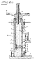
- Fig.2a discloses a part of the housing 1 and the upper edge flange 12 of the rotor 2 and the upper movable sector plate 6.
- One of the support devices 10 is mounted by screws in a hole in the sector plate 6.
- the support device 10 comprises a socket 15 provided with a mounting flange 16, which with an intermediate sealing ring is attached by screws 18 to the sector plate 6.
- the socket 15 is provided with a lid 19, and inside the socket 15 an inner sleeve 20 with open top is positioned with an upper part that is provided with an axial slot 21.
- a cylindrical stop bar 25 is slidably journalled with a small clearance to the inside 33 of the socket 15.
- a bottom plate 24 is situated attached to an adjusting rod 23.
- the stop bar 25 made of carbon or graphite is replaceably attached at the underside of the plate 24 by a set screw 26 screwed into the bottom plate 24.
- the upper end of the socket 15 is provided with a screw 28 screwed into a radial tapped hole 27, which screw has a finger 29 inserted into the slot 21 thus preventing the inner sleeve 20 and the stop bar 25 from turning in the socket 15.
- Adjustment of the clearance between the sector plate 6 and the edge flange 12 is made possible by the inner sleeve 20 with the stop bar 25 being axially displaceable in the socket 15 with the finger 29 in the slot 21 permitting displacement of the of the inner sleeve 20 with the stop bar 25 without turning.
- the displacement can be affected in many ways.
- An uncomplicated and efficient device consists of the rod 23 journalled in a hole 50 of the lid 19, which rod has a fine-threaded part extending through a fine-threaded opening 52 in a wheel 30 which is rotatably journalled on top of the lid 19.
- the rod 23 and the stop rod 25 are displaced in relation to the sector plate 6 when the wheel 30 is turned.
- the rod 23 is locked by the threads of the wheel 30 and the rod 23 working as a self-locking gear.
- a clearance of for instance 4 mm is set between the sector plate 6 and the edge flange 12 by turning of the wheel 30.
- the stop rod 25 will get worn during operation and the sector plate 6 will sink slowly down towards the edge flange 12 correspondingly. The remaining clearance after some time of operation is checked when necessary. When the heat exchanger is new the wear is fast, and the stop rod 25 has to be replaced soon. After that the wear will occur essentially slower because the first stop rod has deposit a layer of lubricating carbon or graphite on the edge flange 12.
- the stop bars are situated in an ambient temperature of normally 350°C and in a usually corrosive atmosphere in which fly ash usually whirls round. Practical tests have proved that it is impossible to prevent an impractically heavy wear of the stop bars due to the formation of irregularities on the edge flanges during their motion between the sector plates.
- the play 31 between the periphery 32 of the stop bar 25 and the inside 33 of the socket 15 therefore has been given, according to the invention, a thickness of a few tenths of a mm, as shown in fig.3a, so that at the supply of a pressure medium through a hollow nipple 34 in the wall of the socket 15 an axial curtain 35 is formed by the pressure medium round the periphery of the stop bar, as shown in fig.2b.
- an efficient cleaning by blowing is obtained of the edge flange 12 round the stop bar 25, and at the same time a cooling of the stop bar and the edge flange.
- a more or less continuous pressure medium curtain is, however, more efficient and easy to attain.
- the stop bar 25 can, for example, be provided with axial recesses or grooves 36 in the peripheral surface, as shown in fig.3b.
- the inside of of the socket 15 can be provided with axial grooves 37, as shown in fig.3c.
Landscapes
- Engineering & Computer Science (AREA)
- Physics & Mathematics (AREA)
- Thermal Sciences (AREA)
- Mechanical Engineering (AREA)
- General Engineering & Computer Science (AREA)
- Heat-Exchange Devices With Radiators And Conduit Assemblies (AREA)
- Power Steering Mechanism (AREA)
- Separation By Low-Temperature Treatments (AREA)
- Braking Arrangements (AREA)
- Electric Propulsion And Braking For Vehicles (AREA)
- Fuel Cell (AREA)
- Processing Of Solid Wastes (AREA)
- Optical Couplings Of Light Guides (AREA)
- Air Bags (AREA)
- Compression-Type Refrigeration Machines With Reversible Cycles (AREA)
Abstract
Description
- fig.1 is a partial axial section through the heat exchanger
- fig.2a is a longitudinal section through a device with a stop bar at a sector plate end taken along line II-II in fig.1,
- fig.3a , fig.3b and fig.3c are sectional views taken along line III-III in fig.2a showing three variants of stop bars with surrounding socket, and
- fig.4 is a sectional view similar to fig.3a and provided with three axial, through channels.
Claims (8)
- A regenerative heat exchanger comprising two parts, one of which being rotary relative to the other round a common centre axis, one of the parts (2) being essentially cylindrical and containing regenerator mass (3), and the remaining part (1) comprising medium ducts having axially directed inlet ducts and outlet ducts for heat emitting and heat absorbing media, which inlets and outlets are separated from each other by sector shaped plates (6,8) positioned for sealing purposes close to the end surfaces of the cylindrical part, which plates are pivotally connected to axially fixed centre plates (5,7) positioned at the ends of the cylindrical part and attached to said remaining part, in addition to which the sector plates (5,6) at their radially outer ends are provided with devices (10) which each comprises at least one cylindrical stop bar (25) for setting a clearance between the ends of the plates and an edge flange (12) or similar means at each end of the cylindrical part (2), which stop bar (11) is mounted axially displaceable in a cylindrical socket (15) at respective sector plate end (6,8) perpendicular to this and adjustable by a screw mechanism (50-53) connected to the sector plate end, characterized in that a play (31) between the periphery of the cylindrical stop bar (25) and the inside of the socket (15) is designed with at least one axial through passage (36,37) that is connected to a pressure source (34) for gas, preferably air, water steam or a similar medium.
- A heat exchanger according to claim 1, characterized in that the play (31) extends essentially all around the periphery of the stop bar (25).
- A heat exchanger according to claim 1, characterized in that the through passage essentially is formed by shallow, axial grooves (36) in the periphery surface of the stop bar (25).
- A heat exchanger according to claim 1, characterized in that the through passage essentially is formed by shallow, axial grooves (37) in the inside of the socket (15).
- A heat exchanger according to any of claims 1-4, characterized in that at least one essentially axial through passage (38) further is arranged within the periphery of the stop bar (25) and connected to the pressure source for gas, preferably for air, water steam or a similar medium.
- A heat exchanger according to claim 2 and 5, characterized in that the play (31) round the periphery of the stop rod (25) is connected to a pressure source with higher pressure than the pressure source for the inner through passage (38).
- A heat exchanger according to any of claims 1-6, charcterized in that the stop rod (25) is journalled in the socket (15) prevented from turning by a guide (21,28) cooperating with the socket (15)
- A heat exchanger according to any of claims 1-7, characterized in that the medium jets directed through the play (31) and the through passages (36, 37, 38) towards the edge flanges (12) create a reaction power sufficient for reducing at least a part of the pressure of the stop bars (25) against the edge flanges (12).
Applications Claiming Priority (3)
| Application Number | Priority Date | Filing Date | Title |
|---|---|---|---|
| SE9502874A SE506021C2 (en) | 1995-08-17 | 1995-08-17 | Regenerative, rotary heat exchanger |
| SE9502874 | 1995-08-17 | ||
| PCT/SE1996/000993 WO1997007374A1 (en) | 1995-08-17 | 1996-08-07 | Rotary regenerative heat exchanger |
Publications (2)
| Publication Number | Publication Date |
|---|---|
| EP0845096A1 EP0845096A1 (en) | 1998-06-03 |
| EP0845096B1 true EP0845096B1 (en) | 2001-06-27 |
Family
ID=20399213
Family Applications (1)
| Application Number | Title | Priority Date | Filing Date |
|---|---|---|---|
| EP96927970A Expired - Lifetime EP0845096B1 (en) | 1995-08-17 | 1996-08-07 | Rotary regenerative heat exchanger |
Country Status (13)
| Country | Link |
|---|---|
| US (1) | US5911270A (en) |
| EP (1) | EP0845096B1 (en) |
| JP (1) | JP2001510547A (en) |
| AT (1) | ATE202628T1 (en) |
| DE (1) | DE69613580T2 (en) |
| ES (1) | ES2160832T3 (en) |
| GR (1) | GR3036299T3 (en) |
| HU (1) | HU220425B (en) |
| IL (1) | IL122865A (en) |
| PL (1) | PL183674B1 (en) |
| PT (1) | PT845096E (en) |
| SE (1) | SE506021C2 (en) |
| WO (1) | WO1997007374A1 (en) |
Families Citing this family (6)
| Publication number | Priority date | Publication date | Assignee | Title |
|---|---|---|---|---|
| US6261092B1 (en) * | 2000-05-17 | 2001-07-17 | Megtec Systems, Inc. | Switching valve |
| US6749815B2 (en) | 2001-05-04 | 2004-06-15 | Megtec Systems, Inc. | Switching valve seal |
| US7325562B2 (en) | 2002-05-07 | 2008-02-05 | Meggec Systems, Inc. | Heated seal air for valve and regenerative thermal oxidizer containing same |
| US6669472B1 (en) | 2002-08-28 | 2003-12-30 | Megtec Systems, Inc. | Dual lift system |
| US7150446B1 (en) | 2002-08-28 | 2006-12-19 | Megtec Systems, Inc. | Dual lift system |
| NO334410B1 (en) | 2010-09-10 | 2014-02-24 | Flexit As | Ventilation System |
Family Cites Families (8)
| Publication number | Priority date | Publication date | Assignee | Title |
|---|---|---|---|---|
| US3010704A (en) * | 1959-02-09 | 1961-11-28 | Air Preheater | Circumferential seal |
| CA983474A (en) * | 1972-09-21 | 1976-02-10 | Gordon J. Faris | Clearance monitoring probe for rotary regenerative heat exchanger |
| US4256171A (en) * | 1979-02-05 | 1981-03-17 | General Motors Corporation | Regenerator seal hub gas passages |
| JPS602008A (en) * | 1983-06-08 | 1985-01-08 | 昭和電線電纜株式会社 | Vertical pulling process of cable |
| US4705098A (en) * | 1986-05-02 | 1987-11-10 | The Babcock & Wilcox Company | Labyrinth articulation joint for regenerative air heater seal frame |
| SE501211C2 (en) * | 1993-06-21 | 1994-12-12 | Svenska Rotor Maskiner Ab | Device for maintaining and controlling the clearance between the sector plates and the generator mass in a rotating, regenerative heat exchanger |
| EP0715706B1 (en) * | 1993-07-02 | 1999-05-19 | Berndt Lindström | Regenerative heat exchanger |
| SE503801E (en) * | 1993-07-02 | 2002-03-20 | Berndt Lindstroem | Regenerative heat exchanger where trailers and airbags maintain play between sector plate and rotor |
-
1995
- 1995-08-17 SE SE9502874A patent/SE506021C2/en not_active IP Right Cessation
-
1996
- 1996-08-07 HU HU9901262A patent/HU220425B/en not_active IP Right Cessation
- 1996-08-07 EP EP96927970A patent/EP0845096B1/en not_active Expired - Lifetime
- 1996-08-07 JP JP50920297A patent/JP2001510547A/en active Pending
- 1996-08-07 ES ES96927970T patent/ES2160832T3/en not_active Expired - Lifetime
- 1996-08-07 IL IL12286596A patent/IL122865A/en not_active IP Right Cessation
- 1996-08-07 PL PL96324902A patent/PL183674B1/en unknown
- 1996-08-07 WO PCT/SE1996/000993 patent/WO1997007374A1/en not_active Ceased
- 1996-08-07 AT AT96927970T patent/ATE202628T1/en not_active IP Right Cessation
- 1996-08-07 DE DE69613580T patent/DE69613580T2/en not_active Expired - Fee Related
- 1996-08-07 US US08/981,484 patent/US5911270A/en not_active Expired - Fee Related
- 1996-08-07 PT PT96927970T patent/PT845096E/en unknown
-
2001
- 2001-07-31 GR GR20010401149T patent/GR3036299T3/en not_active IP Right Cessation
Also Published As
| Publication number | Publication date |
|---|---|
| ATE202628T1 (en) | 2001-07-15 |
| PT845096E (en) | 2001-12-28 |
| GR3036299T3 (en) | 2001-10-31 |
| IL122865A0 (en) | 1998-08-16 |
| SE9502874D0 (en) | 1995-08-17 |
| HU220425B (en) | 2002-01-28 |
| EP0845096A1 (en) | 1998-06-03 |
| US5911270A (en) | 1999-06-15 |
| JP2001510547A (en) | 2001-07-31 |
| PL183674B1 (en) | 2002-06-28 |
| HUP9901262A3 (en) | 2000-12-28 |
| DE69613580T2 (en) | 2002-04-25 |
| DE69613580D1 (en) | 2001-08-02 |
| SE506021C2 (en) | 1997-11-03 |
| SE9502874L (en) | 1997-02-18 |
| PL324902A1 (en) | 1998-06-22 |
| WO1997007374A1 (en) | 1997-02-27 |
| HUP9901262A2 (en) | 1999-08-30 |
| ES2160832T3 (en) | 2001-11-16 |
| IL122865A (en) | 2000-11-21 |
Similar Documents
| Publication | Publication Date | Title |
|---|---|---|
| US4602874A (en) | Support of a machine tool spindle with cooling device in a headstock | |
| US7624754B2 (en) | Double-disk slide valve | |
| US3805935A (en) | Impingement cooling means for friction clutch or disc brake | |
| JP3155553B2 (en) | Spear type water blowing device for cleaning heat exchanger | |
| SE453859B (en) | APPLICATION FOR USE IN CONNECTIONS INTENDED FOR FANTS AND PAVERABLE WITH PRESSURE MEDIUM AND SPRING POWER | |
| US5911270A (en) | Rotary regenerative heat exchanger | |
| AU2002225142B2 (en) | Cooling arrangement for brake caliper | |
| GB2135009A (en) | Soot blower | |
| JPS58191338A (en) | Torque/revolving torque controller | |
| GB2035157A (en) | Hydraulically actuated clamping cylinder for clamping devices on a rotating spindle | |
| US2437670A (en) | Fluid operated clutch | |
| CN115030822A (en) | Bearing cavity sealing device | |
| US4093242A (en) | Slag blower wall box seal | |
| EP0221335B1 (en) | Rotating drum end seal | |
| US2752197A (en) | Rotary nozzle for soot blowers and the like | |
| Xiao et al. | A review of mechanical seals heat transfer augmentation techniques | |
| WO1995000809A1 (en) | Regenerative heat exchanger | |
| EP0830555B1 (en) | Rotary regenerative heat exchanger | |
| EP0807237B1 (en) | Regenerative heat exchanger and a method for operating a regenerative heat exchanger | |
| CZ47398A3 (en) | Rotary regenerative heat-exchange apparatus | |
| JPS5872887A (en) | Rotary regeneration type heat exchanger | |
| US3089468A (en) | Sootblower | |
| US5845700A (en) | Rotary regenerative heat exchanger | |
| CN120638758A (en) | Motor spindle for high-power motor | |
| US1918645A (en) | Hand tool |
Legal Events
| Date | Code | Title | Description |
|---|---|---|---|
| PUAI | Public reference made under article 153(3) epc to a published international application that has entered the european phase |
Free format text: ORIGINAL CODE: 0009012 |
|
| 17P | Request for examination filed |
Effective date: 19971219 |
|
| AK | Designated contracting states |
Kind code of ref document: A1 Designated state(s): AT CH DE ES FR GB GR IE IT LI PT SE |
|
| RAP1 | Party data changed (applicant data changed or rights of an application transferred) |
Owner name: ABB AIR PREHEATER, INC. |
|
| GRAG | Despatch of communication of intention to grant |
Free format text: ORIGINAL CODE: EPIDOS AGRA |
|
| 17Q | First examination report despatched |
Effective date: 20000912 |
|
| GRAG | Despatch of communication of intention to grant |
Free format text: ORIGINAL CODE: EPIDOS AGRA |
|
| GRAH | Despatch of communication of intention to grant a patent |
Free format text: ORIGINAL CODE: EPIDOS IGRA |
|
| GRAH | Despatch of communication of intention to grant a patent |
Free format text: ORIGINAL CODE: EPIDOS IGRA |
|
| GRAA | (expected) grant |
Free format text: ORIGINAL CODE: 0009210 |
|
| AK | Designated contracting states |
Kind code of ref document: B1 Designated state(s): AT CH DE ES FR GB GR IE IT LI PT SE |
|
| REF | Corresponds to: |
Ref document number: 202628 Country of ref document: AT Date of ref document: 20010715 Kind code of ref document: T |
|
| REG | Reference to a national code |
Ref country code: CH Ref legal event code: EP |
|
| REG | Reference to a national code |
Ref country code: IE Ref legal event code: FG4D |
|
| REF | Corresponds to: |
Ref document number: 69613580 Country of ref document: DE Date of ref document: 20010802 |
|
| REG | Reference to a national code |
Ref country code: CH Ref legal event code: NV Representative=s name: E. BLUM & CO. PATENTANWAELTE |
|
| ITF | It: translation for a ep patent filed | ||
| ET | Fr: translation filed | ||
| REG | Reference to a national code |
Ref country code: ES Ref legal event code: FG2A Ref document number: 2160832 Country of ref document: ES Kind code of ref document: T3 |
|
| REG | Reference to a national code |
Ref country code: PT Ref legal event code: SC4A Free format text: AVAILABILITY OF NATIONAL TRANSLATION Effective date: 20010926 |
|
| REG | Reference to a national code |
Ref country code: GB Ref legal event code: IF02 |
|
| PLBE | No opposition filed within time limit |
Free format text: ORIGINAL CODE: 0009261 |
|
| STAA | Information on the status of an ep patent application or granted ep patent |
Free format text: STATUS: NO OPPOSITION FILED WITHIN TIME LIMIT |
|
| 26N | No opposition filed | ||
| PGFP | Annual fee paid to national office [announced via postgrant information from national office to epo] |
Ref country code: PT Payment date: 20020712 Year of fee payment: 7 |
|
| PGFP | Annual fee paid to national office [announced via postgrant information from national office to epo] |
Ref country code: GB Payment date: 20020716 Year of fee payment: 7 |
|
| PGFP | Annual fee paid to national office [announced via postgrant information from national office to epo] |
Ref country code: IE Payment date: 20020731 Year of fee payment: 7 Ref country code: FR Payment date: 20020731 Year of fee payment: 7 |
|
| PGFP | Annual fee paid to national office [announced via postgrant information from national office to epo] |
Ref country code: GR Payment date: 20020807 Year of fee payment: 7 |
|
| PGFP | Annual fee paid to national office [announced via postgrant information from national office to epo] |
Ref country code: SE Payment date: 20020812 Year of fee payment: 7 |
|
| PGFP | Annual fee paid to national office [announced via postgrant information from national office to epo] |
Ref country code: ES Payment date: 20020814 Year of fee payment: 7 Ref country code: DE Payment date: 20020814 Year of fee payment: 7 Ref country code: CH Payment date: 20020814 Year of fee payment: 7 |
|
| PGFP | Annual fee paid to national office [announced via postgrant information from national office to epo] |
Ref country code: AT Payment date: 20020822 Year of fee payment: 7 |
|
| PG25 | Lapsed in a contracting state [announced via postgrant information from national office to epo] |
Ref country code: IE Free format text: LAPSE BECAUSE OF NON-PAYMENT OF DUE FEES Effective date: 20030807 Ref country code: GB Free format text: LAPSE BECAUSE OF NON-PAYMENT OF DUE FEES Effective date: 20030807 Ref country code: AT Free format text: LAPSE BECAUSE OF NON-PAYMENT OF DUE FEES Effective date: 20030807 |
|
| PG25 | Lapsed in a contracting state [announced via postgrant information from national office to epo] |
Ref country code: SE Free format text: LAPSE BECAUSE OF NON-PAYMENT OF DUE FEES Effective date: 20030808 Ref country code: ES Free format text: LAPSE BECAUSE OF NON-PAYMENT OF DUE FEES Effective date: 20030808 |
|
| PG25 | Lapsed in a contracting state [announced via postgrant information from national office to epo] |
Ref country code: LI Free format text: LAPSE BECAUSE OF NON-PAYMENT OF DUE FEES Effective date: 20030831 Ref country code: CH Free format text: LAPSE BECAUSE OF NON-PAYMENT OF DUE FEES Effective date: 20030831 |
|
| PG25 | Lapsed in a contracting state [announced via postgrant information from national office to epo] |
Ref country code: PT Free format text: LAPSE BECAUSE OF NON-PAYMENT OF DUE FEES Effective date: 20040229 |
|
| PG25 | Lapsed in a contracting state [announced via postgrant information from national office to epo] |
Ref country code: DE Free format text: LAPSE BECAUSE OF NON-PAYMENT OF DUE FEES Effective date: 20040302 |
|
| PG25 | Lapsed in a contracting state [announced via postgrant information from national office to epo] |
Ref country code: GR Free format text: LAPSE BECAUSE OF NON-PAYMENT OF DUE FEES Effective date: 20040303 |
|
| EUG | Se: european patent has lapsed | ||
| GBPC | Gb: european patent ceased through non-payment of renewal fee |
Effective date: 20030807 |
|
| REG | Reference to a national code |
Ref country code: CH Ref legal event code: PL |
|
| PG25 | Lapsed in a contracting state [announced via postgrant information from national office to epo] |
Ref country code: FR Free format text: LAPSE BECAUSE OF NON-PAYMENT OF DUE FEES Effective date: 20040430 |
|
| REG | Reference to a national code |
Ref country code: PT Ref legal event code: MM4A Free format text: LAPSE DUE TO NON-PAYMENT OF FEES Effective date: 20040229 |
|
| REG | Reference to a national code |
Ref country code: IE Ref legal event code: MM4A |
|
| REG | Reference to a national code |
Ref country code: FR Ref legal event code: ST |
|
| REG | Reference to a national code |
Ref country code: ES Ref legal event code: FD2A Effective date: 20030808 |
|
| PG25 | Lapsed in a contracting state [announced via postgrant information from national office to epo] |
Ref country code: IT Free format text: LAPSE BECAUSE OF NON-PAYMENT OF DUE FEES;WARNING: LAPSES OF ITALIAN PATENTS WITH EFFECTIVE DATE BEFORE 2007 MAY HAVE OCCURRED AT ANY TIME BEFORE 2007. THE CORRECT EFFECTIVE DATE MAY BE DIFFERENT FROM THE ONE RECORDED. Effective date: 20050807 |