EP0844489B1 - Method to improve the efficiency of RF coil systems, particularly in devices for nuclear magnetic resonance image acquisition, and RF coil system to implement this method - Google Patents
Method to improve the efficiency of RF coil systems, particularly in devices for nuclear magnetic resonance image acquisition, and RF coil system to implement this method Download PDFInfo
- Publication number
- EP0844489B1 EP0844489B1 EP97119705A EP97119705A EP0844489B1 EP 0844489 B1 EP0844489 B1 EP 0844489B1 EP 97119705 A EP97119705 A EP 97119705A EP 97119705 A EP97119705 A EP 97119705A EP 0844489 B1 EP0844489 B1 EP 0844489B1
- Authority
- EP
- European Patent Office
- Prior art keywords
- coils
- coil
- areas
- coil system
- magnetic field
- Prior art date
- Legal status (The legal status is an assumption and is not a legal conclusion. Google has not performed a legal analysis and makes no representation as to the accuracy of the status listed.)
- Expired - Lifetime
Links
- 238000000034 method Methods 0.000 title claims description 15
- 238000005481 NMR spectroscopy Methods 0.000 title claims description 9
- 230000035945 sensitivity Effects 0.000 claims description 27
- 230000000295 complement effect Effects 0.000 claims description 12
- 238000001514 detection method Methods 0.000 claims description 9
- 230000005540 biological transmission Effects 0.000 claims description 5
- 238000002592 echocardiography Methods 0.000 claims description 5
- 230000005284 excitation Effects 0.000 claims description 4
- 238000005452 bending Methods 0.000 claims description 3
- 239000012141 concentrate Substances 0.000 claims description 3
- 238000003780 insertion Methods 0.000 claims description 3
- 230000037431 insertion Effects 0.000 claims description 3
- 230000000877 morphologic effect Effects 0.000 claims description 3
- 238000013421 nuclear magnetic resonance imaging Methods 0.000 claims description 3
- 230000002238 attenuated effect Effects 0.000 claims description 2
- 239000012466 permeate Substances 0.000 claims description 2
- 210000003414 extremity Anatomy 0.000 description 13
- 238000010276 construction Methods 0.000 description 4
- 238000004804 winding Methods 0.000 description 3
- 230000006978 adaptation Effects 0.000 description 2
- 238000003384 imaging method Methods 0.000 description 2
- 238000004519 manufacturing process Methods 0.000 description 2
- 230000003068 static effect Effects 0.000 description 2
- 230000004323 axial length Effects 0.000 description 1
- 239000004020 conductor Substances 0.000 description 1
- 230000001419 dependent effect Effects 0.000 description 1
- 239000006185 dispersion Substances 0.000 description 1
- 210000003141 lower extremity Anatomy 0.000 description 1
- 238000002595 magnetic resonance imaging Methods 0.000 description 1
- 238000011160 research Methods 0.000 description 1
- 230000001629 suppression Effects 0.000 description 1
Images

Classifications
-
- G—PHYSICS
- G01—MEASURING; TESTING
- G01R—MEASURING ELECTRIC VARIABLES; MEASURING MAGNETIC VARIABLES
- G01R33/00—Arrangements or instruments for measuring magnetic variables
- G01R33/20—Arrangements or instruments for measuring magnetic variables involving magnetic resonance
- G01R33/28—Details of apparatus provided for in groups G01R33/44 - G01R33/64
- G01R33/32—Excitation or detection systems, e.g. using radio frequency signals
- G01R33/34—Constructional details, e.g. resonators, specially adapted to MR
- G01R33/34084—Constructional details, e.g. resonators, specially adapted to MR implantable coils or coils being geometrically adaptable to the sample, e.g. flexible coils or coils comprising mutually movable parts
-
- G—PHYSICS
- G01—MEASURING; TESTING
- G01R—MEASURING ELECTRIC VARIABLES; MEASURING MAGNETIC VARIABLES
- G01R33/00—Arrangements or instruments for measuring magnetic variables
- G01R33/20—Arrangements or instruments for measuring magnetic variables involving magnetic resonance
- G01R33/28—Details of apparatus provided for in groups G01R33/44 - G01R33/64
- G01R33/32—Excitation or detection systems, e.g. using radio frequency signals
- G01R33/34—Constructional details, e.g. resonators, specially adapted to MR
- G01R33/34046—Volume type coils, e.g. bird-cage coils; Quadrature bird-cage coils; Circularly polarised coils
- G01R33/34053—Solenoid coils; Toroidal coils
-
- G—PHYSICS
- G01—MEASURING; TESTING
- G01R—MEASURING ELECTRIC VARIABLES; MEASURING MAGNETIC VARIABLES
- G01R33/00—Arrangements or instruments for measuring magnetic variables
- G01R33/20—Arrangements or instruments for measuring magnetic variables involving magnetic resonance
- G01R33/28—Details of apparatus provided for in groups G01R33/44 - G01R33/64
- G01R33/32—Excitation or detection systems, e.g. using radio frequency signals
- G01R33/34—Constructional details, e.g. resonators, specially adapted to MR
- G01R33/34046—Volume type coils, e.g. bird-cage coils; Quadrature bird-cage coils; Circularly polarised coils
- G01R33/34069—Saddle coils
-
- G—PHYSICS
- G01—MEASURING; TESTING
- G01R—MEASURING ELECTRIC VARIABLES; MEASURING MAGNETIC VARIABLES
- G01R33/00—Arrangements or instruments for measuring magnetic variables
- G01R33/20—Arrangements or instruments for measuring magnetic variables involving magnetic resonance
- G01R33/28—Details of apparatus provided for in groups G01R33/44 - G01R33/64
- G01R33/32—Excitation or detection systems, e.g. using radio frequency signals
- G01R33/34—Constructional details, e.g. resonators, specially adapted to MR
- G01R33/341—Constructional details, e.g. resonators, specially adapted to MR comprising surface coils
-
- G—PHYSICS
- G01—MEASURING; TESTING
- G01R—MEASURING ELECTRIC VARIABLES; MEASURING MAGNETIC VARIABLES
- G01R33/00—Arrangements or instruments for measuring magnetic variables
- G01R33/20—Arrangements or instruments for measuring magnetic variables involving magnetic resonance
- G01R33/28—Details of apparatus provided for in groups G01R33/44 - G01R33/64
- G01R33/32—Excitation or detection systems, e.g. using radio frequency signals
- G01R33/36—Electrical details, e.g. matching or coupling of the coil to the receiver
- G01R33/3678—Electrical details, e.g. matching or coupling of the coil to the receiver involving quadrature drive or detection, e.g. a circularly polarized RF magnetic field
-
- G—PHYSICS
- G01—MEASURING; TESTING
- G01R—MEASURING ELECTRIC VARIABLES; MEASURING MAGNETIC VARIABLES
- G01R33/00—Arrangements or instruments for measuring magnetic variables
- G01R33/20—Arrangements or instruments for measuring magnetic variables involving magnetic resonance
- G01R33/44—Arrangements or instruments for measuring magnetic variables involving magnetic resonance using nuclear magnetic resonance [NMR]
- G01R33/48—NMR imaging systems
- G01R33/54—Signal processing systems, e.g. using pulse sequences ; Generation or control of pulse sequences; Operator console
- G01R33/56—Image enhancement or correction, e.g. subtraction or averaging techniques, e.g. improvement of signal-to-noise ratio and resolution
- G01R33/565—Correction of image distortions, e.g. due to magnetic field inhomogeneities
- G01R33/5659—Correction of image distortions, e.g. due to magnetic field inhomogeneities caused by a distortion of the RF magnetic field, e.g. spatial inhomogeneities of the RF magnetic field
Definitions
- the invention relates to a method to improve the efficiency of a quadrature RF coil system for data acquisition in a Nuclear Magnetic Resonance Imaging system, said quadrature RF coil system comprising at least two coils (1, 2; 3, 4), whose corresponding magnetic fields are oriented in directions substantially orthogonal to each other, at least in one portion of the relevant volume, which contains the body or a part thereof under examination and to be imaged.
- the said quadrature coil systems are used both to capture the echoes of nuclear spins induced by at least one exciting pulse, and to transmit the exciting pulses of nuclear spins.
- the receptive sensitivity and the transmission efficiency are both related to the characteristics of the magnetic field associated to the coil system.
- magnetic field associated to each coil of the system refers to the component thereof which is orthogonal to a polarizing static magnetic field.
- the relevant component of the quadrature coil system consists of an appropriate vector addition of the orthogonal components of the magnetic fields associated to the single coils of the system, at least one of the said components being multiplied by a predetermined weighting factor.
- the noise components that the coils receive are incoherent with each other, so the sum of the signals produces a total noise which is only ⁇ 2 and not twice the noise, with a consequent improvement of the signal-to-noise ratio.
- the power of the transmitted radio-frequency signal will be the higher, the more intense the magnetic field associated to the configuration of the coils is.
- the magnetic field resulting from the coil system is to be substantially homogeneous, within a predetermined tolerance range, at least in one predetermined area in which the part, limb or body under examination are to be placed.
- the form and size of the coil system are to be designed in such a way as to enable the parts of the bodies under examination or the relevant areas thereof to enter the areas of the magnetic field of the quadrature coil systems, having a predetermined sensitivity and a sufficient homogeneity.
- the quadrature coil systems are to be as little bulky and expensive as possible.
- the coils in quadrature coil systems are conformed in such a manner that the magnetic field associated thereto have a predetermined sufficient sensitivity, that is a predetermined sufficient intensity of the magnetic field, and with a predetermined homogeneous distribution of the sensitivity throughout the examined area of the body, that is throughout the area enclosed inside the coil.
- This requires forms and configurations of coils ensuring both the sensitivity, i.e. intensity level of the magnetic field associated thereto, and the predetermined homogeneous distribution of the said sensitivity in the relevant volume, to obtain serviceable image information.
- Document DE 43 18 134 discloses a circular polarized local antenna for a Magnetic Resonance apparatus comprising a first and a second partial antenna formed by a first and a second coil which coils enclose a district to be examined in a first position.
- the coils axis are essentially perpendicular one relatively to the other.
- the first coil is mounted in a displaceable way in the sense that in a second position of the said first coil at least an opening of the second coil is generated allowing the passage of the district to be examined, while in a first position of the said first coil, the said first coil encloses the said second coil and at least part of the said openings.
- Document US 5,548,218 discloses an RF coil construction for MRI apparatus comprising preferably three butterfly coils extendinbg in a longitudinal direction and overlapping with three single loop coils. Each of the three butterfly coils have flexible wings which can be wrapped over the body of a patient. The signals from the two of the butterfly coils and two of the single loop coils are simultaneously processed in a phased array manner.
- the resultant RF coil conbstruction provides in-depth imaging over a large FOV with a high SNR and good homogeneity, and is well suited for imaging the lower extremities of a patient without moving the patient or the coils.
- the butterfly coils receive signals in the horizontal direction
- the single loop coils receive signals in the vertical direction. The combining of such signals realizes quadrature operation and improves SNR.
- a mesh coil that can be operated to function as the equivalent of one butterfly coil and one single loop coil.
- the invention is based on the problem to implement a method for improving the efficiency of a coil system of the so-called quadrature type, allowing to get nearer to the theoretical gains, with no considerable cost increase and, at the same time, to limit the space required by the system, and to provide reliable and valuable images for diagnostic purposes.
- the invention solves the above mentioned problem with a method to improve the efficiency of a quadrature RF coil system for data acquisition in a Nuclear Magnetic Resonance Imaging system, according to the preamble of claim 1, further comprising the steps according to the characterising part of claim 1.
- the boundaries between the different areas of concentration of the magnetic field are defined along lines of equal intensity corresponding to a 10% to 30% reduction with respect to the maximum intensity of the field in the complementary areas, especially along lines of equal intensity corresponding to a 20% reduction of the intensity of the magnetic field.
- the values for the definition of the line of equal intensity which defines the boundaries of the complementary areas of higher concentration of the magnetic field are determined, for at least one of the coils, through appropriate weighting by means of factors calculated as a function of the signal-to-noise ratios obtainable with the two coils.
- At least one of the quadrature coils may be deformed in such a manner, that the magnetic field associated thereto and/or the comprehensive one are strongly attenuated or even null, in certain predetermined areas of the relevant volume, corresponding to one or more parts of the body, whose examination is of no interest.
- the invention relates also to a quadrature coil system having the combination of fetures according to claim 6.
- the coils are deformed in such a way as to concentrate the area of higher intensity of the associated magnetic field in one portion of the volume being meant to contain the body under examination and corresponding to a part thereof, strongly reducing or annulling the magnetic field in the areas of the said volume which are outside the predetermined relevant area of the body under examination.
- the efficiency of the quadrature coil system can be improved, and the theoretically reachable gains and efficiency can be obtained.
- the magnetic fields concentrated in predetermined areas and with a predetermined sufficient homogeneity ensure a considerable increase of the signal-to-noise ratio on reception, whereas, in transmitting coil systems, the transmitted power is higher. All this without affecting the fidelity and quality of the obtained image.
- the deformation of the coils also allows for an adaptation of their geometry to the morphology of the body to be examined.
- the coils may be given a shape which is substantially elliptical or anyway flattened on two diametrically opposite sides, hence most of the space required to the more variable dimension of the limb.
- a particular quadrature coil system of this type consists, for example, of an annular, substantially elliptical coil, combined with a double-facing saddle coil, which extends over a surface being elliptical itself, and concentric to the first elliptical coil.
- a further embodiment consists of the combination of an elliptical annular coil and a single-saddle coil.
- the saddle is obtained by arching and bending in the area of two diametrically opposite points which are substantially coincident with the areas in which the elliptical annular coil crosses a second elliptical annular coil.
- This configuration is particularly suitable for the examination of limbs like feet.
- the particular conformation of the coils not only allows to account for the dimensions of the limb which are more variable in size, but, in this case, also facilitates the introduction of the limb itself into the examining position.
- the coil system is adapted to the morphological characteristics of the limb and that the space required by the coil system may be reduced or kept within certain limits, though accounting for the different possible measures or sizes of the bodies under examination.
- most of the space required to take into account the different sizes of the bodies under examination is substantially limited to one direction, that is in the direction of the major axis of the elliptical shape, whereas, in traditional circularly or cylindrically symmetrical coils, a dimensional increase according to an axis would also require an increase according to the axis orthogonal thereto.
- the invention also relates to other enhancements which form the subject of the dependent claims.
- each coil is diagrammatically illustrated, and provided with a very limited number of windings, in order to make the inventive concept clearer.
- each coil is composed of a considerable number of windings, depending on specific needs.
- a quadrature coil system for receiving the echoes of nuclear spins particularly suitable to be used in combination with bodies or limbs having a substantially planar profile, especially for detecting Nuclear Magnetic Resonance images of a hand, comprises a first annular elliptical coil 1.
- the annular elliptical coil 1 generates a magnetic field whose field lines, inside the coil, extend in the axial direction, that is perpendicularly to the plane of the sheet. While the magnetic field generated by a perfectly cylindrical coil would have a very high homogeneity and so a predetermined sensitivity in the whole of its inner volume, the deformation into an ellipse, causes the generation of two areas of concentration of the magnetic field, indicated as B1.
- the magnetic field associated to the coil 1 has a higher intensity.
- the higher intensity of the areas B1 of the magnetic field corresponds, in accordance with the principle of reciprocity, to a higher receptive sensitivity to the echo signals of nuclear spins.
- the areas B1 of higher sensitivity are provided at the opposite ends of the major axis of the elliptical section, as indicated as B1 and B1' in figure 1.
- the magnetic field has lower intensity and thus sensitivity, and such a homogeneity that, in the relevant volume, the field of the coil 1 is no longer homogeneous enough as to ensure a correspondence between the real situation and the detected image.
- the boundary of the areas of higher sensitivity of the magnetic field associated to the coil 1 is defined through criteria that may vary according to the techniques for processing the received signals. These boundaries are determined along lines of equal intensity of the magnetic field associated to the coil 1, corresponding to an attenuation of the intensity of the magnetic field B1 oscillating between 5% and 30%, preferably of 20% with respect to its maximum value.
- a second coil a so-called double-saddle coil, indicated as 2 is associated to the first elliptical coil 1 so as to be concentric thereto.
- the second double-saddle coil is conventionally disposed to be concentric to the first annular coil 1 and is deformed itself in such a manner as to have an elliptical cross section, i.e. to extend over a tubular surface with an elliptical section.
- the rectilinear or axial lengths of the saddle coil 2 may extend, as conventionally arranged, 30°, 150°, 210° and 330° with respect to the axis coinciding with the minor axis of the first elliptical coil 1, in such a way that the angular width of each saddle 102 shall be 120°, otherwise the angular position of the said lengths may be different.
- the angular extension and the corresponding concentration may be extended to the limits which are compatible with the width of the conductors forming the coils, in such a way as to obtain a more precise matching of the complementary zones of sensibility.
- the double-saddle coil 2 generates a magnetic field orthogonal to that of the coil 1, and is deformed in such a way as to contain an area B2 of higher concentration, i.e. of higher intensity, hence of higher sensitivity of the magnetic field, which is coincident with the under-intensity area - as defined according to the above disclosed parameters - of the magnetic field associated to the coil 1, which is provided between the areas B1 of the coil 1.
- the deformation of the two coils 1 and 2 is chosen in such a manner, that the boundaries between the areas B1 and B2 are coincident, and comply with the above disclosed parameters as regards the intensity of the magnetic field, that is its receptive sensitivity, and its homogeneity.
- the extension of the areas B1 and B2 of the magnetic field, generated by the two coils 1, 2 are complementary to each other.
- the comprehensive magnetic field of the two coils together is obtained through an appropriate vector addition of the magnetic fields of the two coils when taken individually.
- the component relating to at least one of the two coils, that is, in this case, to the second saddle coil 2 may be appropriately weighted through a factor which may depend, amongst other things, on the values of the signal-to-noise ratios of the single coils 1, 2.
- the combination of the magnetic fields of the two coils 1, 2 generates a comprehensive field, orthogonal to a polarizing static field covering, with a higher field intensity but with a sufficient homogeneity to obtain valuable images, the whole volume being meant to contain the body under examination or the relevant part thereof.
- the flattening deformation causes a concentration of the field lines in the area B2 and thus a higher field intensity, with respect to that provided by a substantially circular geometry.
- the figures evidently show the advantages of the smaller dimensions of this coil system, with respect to the traditional ones.
- the size variations of the hand are generally substantially limited to a direction parallel to the planar shape of the hand, and in this case to the major axis of the elliptical section, whereas in the perpendicular direction, the hand profile may vary very little.
- the structure with the elliptical section illustrated herein follows much more faithfully the planar shape of the hand and, unlike a structure with a cylindrical shape, it limits the space required to account for the different sizes of the limbs only in the direction of the major axis.
- the higher gain as for the signal-to-noise ratio is self-evident, thanks to the higher density of the lines of the magnetic field which permeates the volume being meant to contain the hand, the said higher density being due to the deformation.
- the example in figures 4 to 6 shows a quadrature coil system particularly suitable to be used in combination with a foot.
- the illustrated configuration accounts for the lack of relevance of certain areas of the limb, for the purpose of an image detection.
- the first annular coil 3 has a shape which is substantially lanceolate, elliptical, or similar.
- the coil 3 is additionally deformed at one of its ends.
- the turns or windings of the coil 3 are laterally curved outwards with respect to the median plane subtended by the central turn or group of turns 103', in particular symmetrically, so that, when seen from the side, in the said area, the turns 103, 103' of the coil 3 take a fan-shaped configuration.
- the coil 3 of the second example has an area of higher sensitivity of the magnetic field which is limited to the area enclosed by the coil 3 on its side opposite to that in which the turns are curved.
- the magnetic field has levels of intensity, thus sensitivity, as well as homogeneity which do not comply with the minimum values defined with reference to the previous example.
- This expedient allows for a considerable reduction of the intensity of the magnetic field associated to the area of the coil 3 with the inclined turns, preventing a sensitivity dispersion in the area corresponding to a part of the foot which is less relevant for the purpose of image detection.
- the centre of deformation of the turns of the coil 3 substantially coincides with the area in which it superposes a second coil 4 which may be defined as a simple saddle coil.
- the coil 4 has an annular shape and is substantially elliptical or oval, being oriented in such a way as to be substantially perpendicular to the coil 3. Moreover, the coil 4 is bent so as to form an inverted V section, with reference to a section plane containing its major axis, the vertex being provided as substantially coincident with the axis which connects the opposite crossing points and, in particular, substantially coincident with the minor axis of the coil 4.
- the V deformation also causes a reduction or substantial suppression of the magnetic field in the area of the volume enclosed by the annular coil 3 opposite to the area B3.
- the comprehensive magnetic field resulting form the vector addition of the orthogonal components of the individual coils 3, 4, one of which being appropriately weighted, has a higher intensity and the required homogeneity, and in addition, the said magnetic field is only limited to the areas of the volume enclosed by the system of coils 3 and 4, which substantially corresponds to a part of the foot being relevant for the purpose of Nuclear Magnetic Resonance image acquisition.
- the heel zone, which is of lower interest for diagnostic researches is found in the area of the volume with a low intensity of the magnetic field.
- the configurations of the quadrature coils illustrated and described with reference to the receiving coils may be also directly applicable to the coils which transmit the excitation pulses of nuclear spins.
- a higher intensity of the magnetic field corresponds to a higher efficiency or power of the transmitting coils. Therefore, both method and construction, as well as functional considerations described and illustrated with reference to the receiving coils may be applicable to transmitting coils.
- the increased efficiency of the transmitting coil system allows for a reduction of an output power of the excitation pulses, and thus for a reduction of energy costs and for a concentration of the available power in the relevant areas of the bodies under examination like in the foot configuration.
- the considerations regarding the space required by the receiving coil system are also applicable for transmitting coil systems.
- the invention is not limited to the embodiments described and illustrated herein, but may be greatly varied, especially as regards construction. Particularly, the invention may be applied to any form of quadrature coils, according to the morphological peculiarities of the body to be examined. Moreover, the inventive concept may be extended, beside the coil systems like those illustrated herein, to all types of means for generating magnetic fields, in particular, intended for other purposes. All this without departure from the guiding principle disclosed above and claimed below.
Landscapes
- Physics & Mathematics (AREA)
- Condensed Matter Physics & Semiconductors (AREA)
- General Physics & Mathematics (AREA)
- Magnetic Resonance Imaging Apparatus (AREA)
- Apparatus For Radiation Diagnosis (AREA)
Description
- The invention relates to a method to improve the efficiency of a quadrature RF coil system for data acquisition in a Nuclear Magnetic Resonance Imaging system, said quadrature RF coil system comprising at least two coils (1, 2; 3, 4), whose corresponding magnetic fields are oriented in directions substantially orthogonal to each other, at least in one portion of the relevant volume, which contains the body or a part thereof under examination and to be imaged.
- Currently, the said quadrature coil systems are used both to capture the echoes of nuclear spins induced by at least one exciting pulse, and to transmit the exciting pulses of nuclear spins.
- The receptive sensitivity and the transmission efficiency are both related to the characteristics of the magnetic field associated to the coil system.
- The expression magnetic field associated to each coil of the system, refers to the component thereof which is orthogonal to a polarizing static magnetic field. The relevant component of the quadrature coil system consists of an appropriate vector addition of the orthogonal components of the magnetic fields associated to the single coils of the system, at least one of the said components being multiplied by a predetermined weighting factor.
- As for the reception of the resonance echoes of nuclear spins, thanks to the sensitivity of the different orthogonal components of the magnetic fields associated to the two quadrature coils, the noise components that the coils receive are incoherent with each other, so the sum of the signals produces a total noise which is only √2 and not twice the noise, with a consequent improvement of the signal-to-noise ratio.
- On transmission, the power of the transmitted radio-frequency signal will be the higher, the more intense the magnetic field associated to the configuration of the coils is.
- Particularly in receiving coil systems, though the reachable theoretical gain of the signal-to-noise ratio through quadrature coils is about 41%, only smaller gains are obtainable in practice, and currently, for certain field configurations, even considerably smaller than the theoretical value.
- This is caused by additional restrictions that the quadrature coil system must meet. First, in order to obtain valuable images for diagnostic purposes from the Nuclear Magnetic Resonance signals, the magnetic field resulting from the coil system is to be substantially homogeneous, within a predetermined tolerance range, at least in one predetermined area in which the part, limb or body under examination are to be placed. Further, the form and size of the coil system are to be designed in such a way as to enable the parts of the bodies under examination or the relevant areas thereof to enter the areas of the magnetic field of the quadrature coil systems, having a predetermined sensitivity and a sufficient homogeneity. In addition to all this, the quadrature coil systems are to be as little bulky and expensive as possible.
- Currently, the coils in quadrature coil systems are conformed in such a manner that the magnetic field associated thereto have a predetermined sufficient sensitivity, that is a predetermined sufficient intensity of the magnetic field, and with a predetermined homogeneous distribution of the sensitivity throughout the examined area of the body, that is throughout the area enclosed inside the coil. This requires forms and configurations of coils ensuring both the sensitivity, i.e. intensity level of the magnetic field associated thereto, and the predetermined homogeneous distribution of the said sensitivity in the relevant volume, to obtain serviceable image information.
- In the attempt to reduce the space requirement of coil systems, advantageous results have been obtained by the production of different types of the said systems, specifically dimensioned for the treatment of one type or some types of limbs. However, the need to have magnetic fields which ensure, inside a predetermined volume, the necessary sensitivity, homogeneously distributed therein, and to account for the different sizes that the limbs may have, always involves huge dimensions of receiving coil systems.
- Document DE 43 18 134 discloses a circular polarized local antenna for a Magnetic Resonance apparatus comprising a first and a second partial antenna formed by a first and a second coil which coils enclose a district to be examined in a first position. The coils axis are essentially perpendicular one relatively to the other. The first coil is mounted in a displaceable way in the sense that in a second position of the said first coil at least an opening of the second coil is generated allowing the passage of the district to be examined, while in a first position of the said first coil, the said first coil encloses the said second coil and at least part of the said openings.
- Document US 5,548,218 discloses an RF coil construction for MRI apparatus comprising preferably three butterfly coils extendinbg in a longitudinal direction and overlapping with three single loop coils. Each of the three butterfly coils have flexible wings which can be wrapped over the body of a patient. The signals from the two of the butterfly coils and two of the single loop coils are simultaneously processed in a phased array manner. The resultant RF coil conbstruction provides in-depth imaging over a large FOV with a high SNR and good homogeneity, and is well suited for imaging the lower extremities of a patient without moving the patient or the coils. Further, the butterfly coils receive signals in the horizontal direction, and the single loop coils receive signals in the vertical direction. The combining of such signals realizes quadrature operation and improves SNR. Also is a mesh coil that can be operated to function as the equivalent of one butterfly coil and one single loop coil.
- The invention is based on the problem to implement a method for improving the efficiency of a coil system of the so-called quadrature type, allowing to get nearer to the theoretical gains, with no considerable cost increase and, at the same time, to limit the space required by the system, and to provide reliable and valuable images for diagnostic purposes.
- The invention solves the above mentioned problem with a method to improve the efficiency of a quadrature RF coil system for data acquisition in a Nuclear Magnetic Resonance Imaging system, according to the preamble of
claim 1, further comprising the steps according to the characterising part ofclaim 1. - Particularly, the boundaries between the different areas of concentration of the magnetic field are defined along lines of equal intensity corresponding to a 10% to 30% reduction with respect to the maximum intensity of the field in the complementary areas, especially along lines of equal intensity corresponding to a 20% reduction of the intensity of the magnetic field.
- The values for the definition of the line of equal intensity which defines the boundaries of the complementary areas of higher concentration of the magnetic field are determined, for at least one of the coils, through appropriate weighting by means of factors calculated as a function of the signal-to-noise ratios obtainable with the two coils.
- According to a further characteristic of the method and of the coil system, at least one of the quadrature coils may be deformed in such a manner, that the magnetic field associated thereto and/or the comprehensive one are strongly attenuated or even null, in certain predetermined areas of the relevant volume, corresponding to one or more parts of the body, whose examination is of no interest.
- The invention relates also to a quadrature coil system having the combination of fetures according to claim 6.
- Advantageously, the coils are deformed in such a way as to concentrate the area of higher intensity of the associated magnetic field in one portion of the volume being meant to contain the body under examination and corresponding to a part thereof, strongly reducing or annulling the magnetic field in the areas of the said volume which are outside the predetermined relevant area of the body under examination.
- Thanks to these expedients, the efficiency of the quadrature coil system can be improved, and the theoretically reachable gains and efficiency can be obtained. The magnetic fields concentrated in predetermined areas and with a predetermined sufficient homogeneity ensure a considerable increase of the signal-to-noise ratio on reception, whereas, in transmitting coil systems, the transmitted power is higher. All this without affecting the fidelity and quality of the obtained image.
- As far as the economical costs for construction and implementation are concerned, the deformation of the coils, when compared to the traditional combination of perfectly circular coils, with pairs of perfectly symmetrical rotation saddle coils, that is expanding along cylindrical generatrices, does not require a considerable increase of manufacturing costs.
- The deformation of the coils also allows for an adaptation of their geometry to the morphology of the body to be examined.
- Thus, for example, in a device for Nuclear Magnetic Resonance image detection, comprising quadrature coil systems for reception and/or transmission, and being meant for the examination of substantially flat bodies or limbs, the coils may be given a shape which is substantially elliptical or anyway flattened on two diametrically opposite sides, hence most of the space required to the more variable dimension of the limb.
- A particular quadrature coil system of this type consists, for example, of an annular, substantially elliptical coil, combined with a double-facing saddle coil, which extends over a surface being elliptical itself, and concentric to the first elliptical coil.
- A further embodiment consists of the combination of an elliptical annular coil and a single-saddle coil.
- Especially in this case, the saddle is obtained by arching and bending in the area of two diametrically opposite points which are substantially coincident with the areas in which the elliptical annular coil crosses a second elliptical annular coil. This configuration is particularly suitable for the examination of limbs like feet. The particular conformation of the coils not only allows to account for the dimensions of the limb which are more variable in size, but, in this case, also facilitates the introduction of the limb itself into the examining position.
- In both cases, it is evident that the coil system is adapted to the morphological characteristics of the limb and that the space required by the coil system may be reduced or kept within certain limits, though accounting for the different possible measures or sizes of the bodies under examination.
- In the case of the two examples, most of the space required to take into account the different sizes of the bodies under examination, is substantially limited to one direction, that is in the direction of the major axis of the elliptical shape, whereas, in traditional circularly or cylindrically symmetrical coils, a dimensional increase according to an axis would also require an increase according to the axis orthogonal thereto.
- The invention also relates to other enhancements which form the subject of the dependent claims.
- The characteristics of the invention and the advantages derived therefrom will be understood more clearly form the following description of some embodiments illustrated without restriction in the accompanying drawings, in which:
- Fig. 1 shows a first embodiment of a receiving quadrature coil system according to the invention, particularly suitable for the detection of Nuclear Magnetic Resonance images of bodies like hands, or similar, or anyway substantially flat.
- Fig. 2 and fig. 3 are diagrammatic views, sectional with respect to the axes of the elliptical generatrix, of the complementary areas of concentration of the magnetic field.
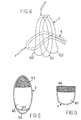
- Fig. 4 shows a variant embodiment of the coil system according to the invention, particularly suitable for bodies like feet, or similar.
- Figs. 5 and 6 show, like figures 2 and 3, the complementary areas of concentration and thus of higher field sensitivity of the two quadrature coils according to fig. 4.
- In the annexed figures, the coils are diagrammatically illustrated, and provided with a very limited number of windings, in order to make the inventive concept clearer. In fact, each coil is composed of a considerable number of windings, depending on specific needs.
- Referring to figs. 1 to 3, a quadrature coil system for receiving the echoes of nuclear spins, particularly suitable to be used in combination with bodies or limbs having a substantially planar profile, especially for detecting Nuclear Magnetic Resonance images of a hand, comprises a first annular
elliptical coil 1. The annularelliptical coil 1 generates a magnetic field whose field lines, inside the coil, extend in the axial direction, that is perpendicularly to the plane of the sheet. While the magnetic field generated by a perfectly cylindrical coil would have a very high homogeneity and so a predetermined sensitivity in the whole of its inner volume, the deformation into an ellipse, causes the generation of two areas of concentration of the magnetic field, indicated as B1. In these areas B1, the magnetic field associated to thecoil 1 has a higher intensity. The higher intensity of the areas B1 of the magnetic field corresponds, in accordance with the principle of reciprocity, to a higher receptive sensitivity to the echo signals of nuclear spins. The areas B1 of higher sensitivity are provided at the opposite ends of the major axis of the elliptical section, as indicated as B1 and B1' in figure 1. - In the remaining central area, the magnetic field has lower intensity and thus sensitivity, and such a homogeneity that, in the relevant volume, the field of the
coil 1 is no longer homogeneous enough as to ensure a correspondence between the real situation and the detected image. - The boundary of the areas of higher sensitivity of the magnetic field associated to the
coil 1 is defined through criteria that may vary according to the techniques for processing the received signals. These boundaries are determined along lines of equal intensity of the magnetic field associated to thecoil 1, corresponding to an attenuation of the intensity of the magnetic field B1 oscillating between 5% and 30%, preferably of 20% with respect to its maximum value. - A second coil, a so-called double-saddle coil, indicated as 2, is associated to the first
elliptical coil 1 so as to be concentric thereto. The second double-saddle coil is conventionally disposed to be concentric to the firstannular coil 1 and is deformed itself in such a manner as to have an elliptical cross section, i.e. to extend over a tubular surface with an elliptical section. - The rectilinear or axial lengths of the
saddle coil 2 may extend, as conventionally arranged, 30°, 150°, 210° and 330° with respect to the axis coinciding with the minor axis of the firstelliptical coil 1, in such a way that the angular width of eachsaddle 102 shall be 120°, otherwise the angular position of the said lengths may be different. For example it is possible to increase the angular extension of eachsaddle 102 in order to concentrate the rectilinear sectors in the region of the axis which is coincident with the minor axis of the firstelliptical coil 1. - Particularly the angular extension and the corresponding concentration may be extended to the limits which are compatible with the width of the conductors forming the coils, in such a way as to obtain a more precise matching of the complementary zones of sensibility.
- The double-
saddle coil 2 generates a magnetic field orthogonal to that of thecoil 1, and is deformed in such a way as to contain an area B2 of higher concentration, i.e. of higher intensity, hence of higher sensitivity of the magnetic field, which is coincident with the under-intensity area - as defined according to the above disclosed parameters - of the magnetic field associated to thecoil 1, which is provided between the areas B1 of thecoil 1. The deformation of the twocoils - Therefore, the extension of the areas B1 and B2 of the magnetic field, generated by the two
coils second saddle coil 2 may be appropriately weighted through a factor which may depend, amongst other things, on the values of the signal-to-noise ratios of thesingle coils coils - Even in the double-
saddle coil 2, the flattening deformation causes a concentration of the field lines in the area B2 and thus a higher field intensity, with respect to that provided by a substantially circular geometry. - The figures evidently show the advantages of the smaller dimensions of this coil system, with respect to the traditional ones. In fact, the size variations of the hand are generally substantially limited to a direction parallel to the planar shape of the hand, and in this case to the major axis of the elliptical section, whereas in the perpendicular direction, the hand profile may vary very little. The structure with the elliptical section illustrated herein follows much more faithfully the planar shape of the hand and, unlike a structure with a cylindrical shape, it limits the space required to account for the different sizes of the limbs only in the direction of the major axis.
- The higher gain as for the signal-to-noise ratio is self-evident, thanks to the higher density of the lines of the magnetic field which permeates the volume being meant to contain the hand, the said higher density being due to the deformation.
- The example in figures 4 to 6 shows a quadrature coil system particularly suitable to be used in combination with a foot.
- In this case, beside the simple adaptation to the complex profile of the foot, it is necessary to provide that the insertion of the limb into the predetermined volume inside the coil system and its rest therein are comfortable. Moreover, the illustrated configuration accounts for the lack of relevance of certain areas of the limb, for the purpose of an image detection.
- In this example, the first annular coil 3 has a shape which is substantially lanceolate, elliptical, or similar.
- However, since in this case, the area of the foot heel is of lower interest, for the purpose of image detection, according to a further characteristic, as shown in fig. 4, the coil 3 is additionally deformed at one of its ends. As shown in fig. 4, in the area of one half of the coil 3, on one of the sides of its minor axis, the turns or windings of the coil 3 are laterally curved outwards with respect to the median plane subtended by the central turn or group of turns 103', in particular symmetrically, so that, when seen from the side, in the said area, the
turns 103, 103' of the coil 3 take a fan-shaped configuration. - Thanks to this deformation, the coil 3 of the second example has an area of higher sensitivity of the magnetic field which is limited to the area enclosed by the coil 3 on its side opposite to that in which the turns are curved. In the remaining area, the magnetic field has levels of intensity, thus sensitivity, as well as homogeneity which do not comply with the minimum values defined with reference to the previous example.
- This expedient allows for a considerable reduction of the intensity of the magnetic field associated to the area of the coil 3 with the inclined turns, preventing a sensitivity dispersion in the area corresponding to a part of the foot which is less relevant for the purpose of image detection.
- The centre of deformation of the turns of the coil 3 substantially coincides with the area in which it superposes a second coil 4 which may be defined as a simple saddle coil.
- The coil 4 has an annular shape and is substantially elliptical or oval, being oriented in such a way as to be substantially perpendicular to the coil 3. Moreover, the coil 4 is bent so as to form an inverted V section, with reference to a section plane containing its major axis, the vertex being provided as substantially coincident with the axis which connects the opposite crossing points and, in particular, substantially coincident with the minor axis of the coil 4.
- As is shown in figure 6, the area of the magnetic field associated to the coil 4, indicated as B4, in which the magnetic field has a higher intensity, coincides with the central area of the coil 4, directly next to the area of higher intensity B3 of the coil 3. The V deformation also causes a reduction or substantial suppression of the magnetic field in the area of the volume enclosed by the annular coil 3 opposite to the area B3.
- In this embodiment, the comprehensive magnetic field resulting form the vector addition of the orthogonal components of the individual coils 3, 4, one of which being appropriately weighted, has a higher intensity and the required homogeneity, and in addition, the said magnetic field is only limited to the areas of the volume enclosed by the system of coils 3 and 4, which substantially corresponds to a part of the foot being relevant for the purpose of Nuclear Magnetic Resonance image acquisition. The heel zone, which is of lower interest for diagnostic researches is found in the area of the volume with a low intensity of the magnetic field.
- The criteria for choosing the boundary lines between the areas B3 and B4 correspond to those disclosed above, with reference to the example of figures 1 to 3, and the coils 3 and 4 are deformed in such a way as to comply with those criteria.
- As for the dimensions of the coil system and the higher gain of the signal-to-noise ratio, the same considerations relating to the previous example, referred to figures 1 to 3, will be applicable.
- According to the principle of reciprocity, which is applicable in this case, the configurations of the quadrature coils illustrated and described with reference to the receiving coils may be also directly applicable to the coils which transmit the excitation pulses of nuclear spins. A higher intensity of the magnetic field corresponds to a higher efficiency or power of the transmitting coils. Therefore, both method and construction, as well as functional considerations described and illustrated with reference to the receiving coils may be applicable to transmitting coils.
- The increased efficiency of the transmitting coil system allows for a reduction of an output power of the excitation pulses, and thus for a reduction of energy costs and for a concentration of the available power in the relevant areas of the bodies under examination like in the foot configuration. In addition, the considerations regarding the space required by the receiving coil system are also applicable for transmitting coil systems.
- Naturally, the invention is not limited to the embodiments described and illustrated herein, but may be greatly varied, especially as regards construction. Particularly, the invention may be applied to any form of quadrature coils, according to the morphological peculiarities of the body to be examined. Moreover, the inventive concept may be extended, beside the coil systems like those illustrated herein, to all types of means for generating magnetic fields, in particular, intended for other purposes. All this without departure from the guiding principle disclosed above and claimed below.
Claims (20)
- Method to improve the efficiency of a quadrature RF coil system for data acquisition in a Nuclear Magnetic Resonance Imaging system, said quadrature RF coil system comprising at least two coils (1, 2; 3, 4), whose corresponding magnetic fields are oriented in directions substantially orthogonal to each other, at least in one portion of the relevant volume, which contains the body or a part thereof under examination and to be imaged, said method comprising the following steps:a) deformation of at least one, preferably of both coils (1, 2; 3, 4) of said quadrature RF coil system, according to the peculiar geometrical characteristics of the parts, i.e. limbs, or bodies to be examined / imaged,b) in such a way that the magnetic fields individually associated to each of the two coils (1, 2; 3, 4) have, within the relevant volume different and substantially complementary areas (B1, B2, B3, B4) of higher and of lower concentration, hence of higher and of lower intensity of the magnetic field, i.e. of higher and of lower sensitivity or efficiency of said quadrature coil system, the combination of the said complementary areas (B1, B2, B3, B4), corresponding to an appropriately weighted vector addition of said magnetic fields (B1, B2; B3, B4) individually associated to each of said two coils (1, 2; 3, 4),c) said deformation of at least one and/or of both of the coils of said quadrature RF coil system (1, 2; 3, 4) being carried out, until a predetermined sensitivity of said quadrature RF coil system in said relevant volume and a predetermined homogeneity of said magnetic field, corresponding to an appropriately weighted vector addition of said magnetic fields (B1, B2; B3, B4) individually associated to each of said two coils (1, 2; 3, 4), has been obtained.
- Method as claimed in claim 1, characterized in that said coils (1, 2; 3, 4) are deformed in such a manner that the boundaries between the different areas (B1, B2, B3, B4) of higher sensitivity of said RF quadrature coil system are defined along lines of equal intensity/sensitivity corresponding to a 10% to 30% reduction with respect to the maximum intensity or sensitivity of / to the field in said different areas (B1, B2, B3, B4), especially along lines of equal intensity / sensitivity corresponding to a 20% reduction of the intensity / sensitivity of the magnetic field with respect to its maximum value.
- Method as claimed in claim 1 or 2, characterized in that the values for the definition of the line of equal intensity which defines the boundaries of the complementary areas (B1, B2; B3, B4) of higher concentration of the magnetic field are determined, for at least one of the two coils (1, 2; 3, 4), through appropriate weighting by means of factors calculated as a function of the signal-to-noise ratios obtainable with the two coils.
- Method as claimed in one or more of the preceding claims, characterized in that at least one of the two quadrature coils (1, 2; 3, 4) may be deformed in such a manner, that the magnetic field associated thereto is strongly attenuated or even null, in certain predetermined areas (B5) of the relevant volume, corresponding to one or more parts of the body, whose examination is of no interest.
- Method as claimed in one or more of the preceding claims 1 to 4 characterised in that the coil system defines a volume for housing the parts of the body under examination or the relevant areas thereof having an open side and the deformation of at least one of the said coils is such as to enable the parts of the body under examination or the relevant areas thereof to enter the quadrature coil system by insertion into the said volume of the coil system through said open side thereof.
- Quadrature coil system, wherein the two coils (1, 2; 3, 4) are sensitive to or generate orthogonal magnetic fields (B1, B2; B3, B4) at least in one portion of the volume being meant to contain a body, a part thereof, or a limb under examination, at least one of the said coils (1, 2; 3, 4), preferably both of them, being deformed according to the geometrical / morphological characteristics of the body under examination and in such a way that the magnetic fields associated thereto contain areas (B1, B2; B3, B4) of higher concentration and intensity of the magnetic field within the volume which is meant to contain at least one relevant part of the body under examination, for the detection of Nuclear Magnetic Resonance images of that part, the said areas (B1, B2; B3, B4) of higher concentration, i.e. intensity of the said magnetic fields complementing each other to obtain a magnetic field with a predetermined intensity and with a predetermined homogeneity, which permeates the whole volume being meant to contain the body under examination or a part thereof
characterised in that the deformation of at least one of the said coils is carried out until a predetermined level of receive sensitivity has benn obtained and a predetermined homogeneity and that the coil or coils (1, 2; 3, 4) are deformed in such a way that the boundaries between the different complementary areas (B1, B2; B3, B4) of higher and of lower concentration of the magnetic fields are defined along lines of equal intensity of the magnetic field, corresponding to a predetermined attenuation with respect to the maximum value. - Coil system as claimed in claim 6, characterized in that the coils (3, 4) are deformed in such a way as to concentrate the areas (B3, B4) of higher intensity of their respective magnetic fields, and/or the magnetic field resulting form the combination of the fields associated to the said two coils, only in one portion of the volume being meant to contain the body under examination and corresponding to a predetermined part thereof, strongly reducing or annulling the magnetic field in the areas (B5) of the said volume which are outside the predetermined relevant area of the body under examination.
- System as claimed in claims 6 or 7, characterized in that the coils (1, 2) are deformed in such a manner, that the boundaries between the different areas (B1, B2; B3, B4) of higher concentration of the magnetic field are defined along lines of equal intensity corresponding to a 10% to 30% reduction with respect tothe maximum intensity of the field in the complementary areas (B1, B2; B3, B4), especially along lines of equal intensity corresponding to a 20% reduction of the intensity of the magnetic field.
- Coil system as claimed in one or more of the preceding claims 6 to 8 characterized in that the values for the definition of the line of equal intensity which defines the boundaries of the complementary areas (B1, B2; B3, B4) of higher concentration of the magnetic field are determined, for at least one of the two coils (2, 4), through appropriate weighting by means of factors calculated as a function of the signal-to-noise ratios obtainable with the two coils.
- Coil system as claimed in one or more of the preceding claims 6 to 9 characterised in that the coil system defines a volume for housing the parts of the body under examination or the relevant areas thereof having an open side and the deformation of at least one of the said coils is such at to enable the parts of the body under examination or the relevant areas thereof to enter the quadrature coil system by insertion into the said volume of the coil system through said open side thereof.
- Coil system as claimed in one or more of the preceding claims 6 to 10, characterized in that the coils (1, 2) are conformed in such a manner as to delimit a detection volume being suitable for bodies with a planar profile, one coil (1) having a substantially annular, elliptical or oval shape, and the other coil (2) being of the so-called double-saddle type, and disposed to be concentric to the annular, elliptical one (1).
- System as claimed in claim 11, characterized in that the double-saddle coil (2) extends over a tubular surface with a cylindrical section, whereas the two saddles may have any angular widths.
- System as claimed in one or more of the preceding claims 6 to 11, characterized in that a coil (3) has an annular, oval or lanceolate shape, its turns (103, 103') being at least partially laterally inclined or arched outwards at one of the two ends on one side of the minor axis.
- System as claimed in one or more of the preceding claims 6 to 13, characterized in that one of the coils (4) has an annular, substantially elliptical or oval shape, being bent and arched in a V shape, substantially about an axis or with a vertex parallel to a predetermined axis.
- System as claimed in claim 14, characterized in that the bending or arching axis is parallel to, especially coincident with the minor axis, or with an axis parallel thereto.
- System as claimed in claims 14 or 15, characterized in that the bending or arching axis is coincident with an axis which connects the points in which one coil (3) crosses or superposes the other coil (4).
- System as claimed in one or more of the preceding claims 10 to 16, characterized in that the two coils (3, 4) have different mutual orientation, preferably perpendicular and have two diametrically opposite crossing and/or superposing areas.
- Coil system as claimed in one or more of claims 13 to 17, characterized in that the turns (103) are laterally inclined outwards, being symmetrical with respect to the median plane subtended by them, in such a way as to have a substantially fan-shaped configuration, whose fulcrum is substantially in the area in which the simple-saddle coil (4) is crossed.
- Method as claimed in one or more of the claims 1 to 5, characterized in that the coil system (1, 2; 3, 4) is made of the coils for the reception of the response echoes of nuclear spins or of the coils for the transmission of the excitation pulse or pulses of nuclear spins in a system for Nuclear Magnetic Resonance image detection.
- Coil system as claimed in one or more of the claims 6 to 18, characterized in that it is made of the coils for the reception of the response echoes of nuclear spins or of the coils for the transmission of the excitation pulse or pulses of nuclear spins in a system for Nuclear Magnetic Resonance image detection.
Applications Claiming Priority (2)
| Application Number | Priority Date | Filing Date | Title |
|---|---|---|---|
| IT96SV000039A IT1288452B1 (en) | 1996-11-20 | 1996-11-20 | METHOD FOR IMPROVING THE EFFICIENCY OF REEL SYSTEMS IN PARTICULAR IN IMAGE ACQUISITION DEVICES USING |
| ITSV960039 | 1996-11-20 |
Publications (2)
| Publication Number | Publication Date |
|---|---|
| EP0844489A1 EP0844489A1 (en) | 1998-05-27 |
| EP0844489B1 true EP0844489B1 (en) | 2006-02-01 |
Family
ID=11408185
Family Applications (1)
| Application Number | Title | Priority Date | Filing Date |
|---|---|---|---|
| EP97119705A Expired - Lifetime EP0844489B1 (en) | 1996-11-20 | 1997-11-11 | Method to improve the efficiency of RF coil systems, particularly in devices for nuclear magnetic resonance image acquisition, and RF coil system to implement this method |
Country Status (5)
| Country | Link |
|---|---|
| US (1) | US6265876B1 (en) |
| EP (1) | EP0844489B1 (en) |
| DE (1) | DE69735179T2 (en) |
| ES (1) | ES2255093T3 (en) |
| IT (1) | IT1288452B1 (en) |
Families Citing this family (5)
| Publication number | Priority date | Publication date | Assignee | Title |
|---|---|---|---|---|
| US6493572B1 (en) | 1999-09-30 | 2002-12-10 | Toshiba America Mri, Inc. | Inherently de-coupled sandwiched solenoidal array coil |
| US6586932B1 (en) * | 2002-10-16 | 2003-07-01 | Schlumberger Technology Corporation | Enhanced performance antennas for NMR logging |
| EP1977264A2 (en) | 2005-10-28 | 2008-10-08 | Koninklijke Philips Electronics N.V. | Non-cylindrical rf coil for mri |
| US7446532B1 (en) * | 2007-07-18 | 2008-11-04 | Varian, Inc. | Arched saddle-shaped NMR RF coils |
| DE102017201883B4 (en) * | 2017-02-07 | 2019-03-28 | Siemens Healthcare Gmbh | Weighting matrix for reducing artifacts in parallel imaging |
Family Cites Families (15)
| Publication number | Priority date | Publication date | Assignee | Title |
|---|---|---|---|---|
| US4766383A (en) * | 1987-02-24 | 1988-08-23 | Kabushiki Kaisha Toshiba | Quadrature antenna for magnetic resonance imaging using elliptical coils |
| GB2208937B (en) * | 1987-08-21 | 1992-04-01 | Fuji Electric Co Ltd | High frequency coil |
| US4820988A (en) | 1987-10-07 | 1989-04-11 | The Regents Of The University Of California | Magnetic gradient coil set for nuclear magnetic resonace system having substantially different coil-patient spacings |
| US4897604A (en) | 1989-02-21 | 1990-01-30 | The Regents Of The University Of California | Method and apparatus for selective adjustment of RF coil size for magnetic resonance imaging |
| DE3918743A1 (en) * | 1989-06-08 | 1990-12-13 | Philips Patentverwaltung | HIGH FREQUENCY SQUARE COIL ARRANGEMENT |
| US5278504A (en) | 1989-06-16 | 1994-01-11 | Picker International, Inc. | Gradient coil with off center sweet spot for magnetic resonance imaging |
| US5424643A (en) | 1989-06-16 | 1995-06-13 | Picker International, Inc. | Magnetic resonance gradient sheet coils |
| US5177441A (en) | 1989-06-16 | 1993-01-05 | Picker International, Inc. | Elliptical cross section gradient oil |
| US5451875A (en) | 1989-06-16 | 1995-09-19 | Picker International, Inc. | Technique for reducing aliasing artifacts wtih insertable gradient coils |
| EP0430103B1 (en) | 1989-11-24 | 1995-06-14 | Kabushiki Kaisha Toshiba | Receiver coil for nuclear magnetic resonance imaging apparatus |
| GB9119574D0 (en) * | 1991-09-13 | 1991-10-23 | Marconi Gec Ltd | Magnetic resonance methods and apparatus |
| US5379767A (en) * | 1992-09-02 | 1995-01-10 | The Regents Of The University Of California | MRI RF coil using zero-pitch solenoidal winding |
| DE4318134C2 (en) | 1993-06-01 | 1999-02-11 | Siemens Ag | Circularly polarizing local antenna |
| US5351688A (en) * | 1993-08-16 | 1994-10-04 | Univ. Of Ne Board Of Regents | NMR quadrature detection solenoidal coils |
| US5370118A (en) * | 1993-12-23 | 1994-12-06 | Medical Advances, Inc. | Opposed loop-pair quadrature NMR coil |
-
1996
- 1996-11-20 IT IT96SV000039A patent/IT1288452B1/en active IP Right Grant
-
1997
- 1997-11-11 EP EP97119705A patent/EP0844489B1/en not_active Expired - Lifetime
- 1997-11-11 DE DE69735179T patent/DE69735179T2/en not_active Expired - Lifetime
- 1997-11-11 ES ES97119705T patent/ES2255093T3/en not_active Expired - Lifetime
-
2000
- 2000-06-30 US US09/608,018 patent/US6265876B1/en not_active Expired - Lifetime
Also Published As
| Publication number | Publication date |
|---|---|
| IT1288452B1 (en) | 1998-09-22 |
| US6265876B1 (en) | 2001-07-24 |
| DE69735179T2 (en) | 2006-10-12 |
| EP0844489A1 (en) | 1998-05-27 |
| DE69735179D1 (en) | 2006-04-13 |
| ITSV960039A1 (en) | 1998-05-20 |
| ES2255093T3 (en) | 2006-06-16 |
Similar Documents
| Publication | Publication Date | Title |
|---|---|---|
| US6701177B2 (en) | Flexible, region-selectable inherently de-coupled sandwiched solenoidal array coil | |
| US5682098A (en) | Open quadrature whole volume imaging NMR surface coil array including three figure-8 shaped surface coils | |
| Wald et al. | Proton spectroscopic imaging of the human brain using phased array detectors | |
| US5917324A (en) | MR apparatus provided with a cylindrical coil system and a surface coil system | |
| EP0256520B1 (en) | Nmr local coil network | |
| EP0598063B1 (en) | Geometrically isolated multiple port volume mri receiving coil comprising multiple quadrature coils | |
| US5951474A (en) | Magnetic resonance imaging apparatus for detecting magnetic resonance signals by radio frequency receiving coils | |
| US5548218A (en) | Flexible RF coils for MRI system | |
| US5664568A (en) | Split-top, neck and head vascular array for magnetic resonance imaging | |
| EP0344293B1 (en) | Nuclear magnetic resonance (nmr) imaging with multiple surface coils | |
| US4665368A (en) | NMR imaging apparatus | |
| US7386338B2 (en) | Bilateral imaging apparatus | |
| US7098659B2 (en) | Method for mode formation, method for mode provision, and reception unit for a magnetic resonance device | |
| CN107076813B (en) | System and method for low-field, multi-channel imaging | |
| JPH0951886A (en) | Magnetic resonance device | |
| JP2001104286A (en) | Magnetic resonance equipment | |
| US6229310B1 (en) | Magnetic resonance imaging excitation and reception methods and apparatus | |
| JPH08173400A (en) | Shape variance mri coil | |
| US4712068A (en) | RF coil arrangement for NMR examination apparatus | |
| US4817612A (en) | Cross-coupled double loop receiver coil for NMR imaging of cardiac and thoraco-abdominal regions of the human body | |
| US4906933A (en) | Quadrature surface coil | |
| US6265876B1 (en) | Method to improve the efficiency of coil systems, particularly in devices for nuclear magnetic resonance image acquisition, and coil system to implement this method | |
| US5241272A (en) | Circularly polarizing local antenna for a nuclear magnetic resonance imaging apparatus | |
| US7279898B2 (en) | MRI RF surface coil with reduced sensitivity in proximity of conductors | |
| US4767993A (en) | Coil system for magnetic resonance imaging |
Legal Events
| Date | Code | Title | Description |
|---|---|---|---|
| PUAI | Public reference made under article 153(3) epc to a published international application that has entered the european phase |
Free format text: ORIGINAL CODE: 0009012 |
|
| AK | Designated contracting states |
Kind code of ref document: A1 Designated state(s): DE ES FR GB IT |
|
| AX | Request for extension of the european patent |
Free format text: AL;LT;LV;MK;RO;SI |
|
| 17P | Request for examination filed |
Effective date: 19981020 |
|
| AKX | Designation fees paid |
Free format text: DE ES FR GB IT |
|
| RBV | Designated contracting states (corrected) |
Designated state(s): DE ES FR GB IT |
|
| 17Q | First examination report despatched |
Effective date: 20020617 |
|
| GRAP | Despatch of communication of intention to grant a patent |
Free format text: ORIGINAL CODE: EPIDOSNIGR1 |
|
| GRAS | Grant fee paid |
Free format text: ORIGINAL CODE: EPIDOSNIGR3 |
|
| RAP1 | Party data changed (applicant data changed or rights of an application transferred) |
Owner name: ESAOTE S.P.A. |
|
| GRAA | (expected) grant |
Free format text: ORIGINAL CODE: 0009210 |
|
| RTI1 | Title (correction) |
Free format text: METHOD TO IMPROVE THE EFFICIENCY OF RF COIL SYSTEMS, PARTICULARLY IN DEVICES FOR NUCLEAR MAGNETIC RESONANCE IMAGE ACQUISI |
|
| AK | Designated contracting states |
Kind code of ref document: B1 Designated state(s): DE ES FR GB IT |
|
| PG25 | Lapsed in a contracting state [announced via postgrant information from national office to epo] |
Ref country code: IT Free format text: LAPSE BECAUSE OF FAILURE TO SUBMIT A TRANSLATION OF THE DESCRIPTION OR TO PAY THE FEE WITHIN THE PRE;WARNING: LAPSES OF ITALIAN PATENTS WITH EFFECTIVE DATE BEFORE 2007 MAY HAVE OCCURRED AT ANY TIME BEFORE 2007. THE CORRECT EFFECTIVE DATE MAY BE DIFFERENT FROM THE ONE RECORDED.SCRIBED TIME-LIMIT Effective date: 20060201 |
|
| REG | Reference to a national code |
Ref country code: GB Ref legal event code: FG4D |
|
| REF | Corresponds to: |
Ref document number: 69735179 Country of ref document: DE Date of ref document: 20060413 Kind code of ref document: P |
|
| REG | Reference to a national code |
Ref country code: ES Ref legal event code: FG2A Ref document number: 2255093 Country of ref document: ES Kind code of ref document: T3 |
|
| RAP2 | Party data changed (patent owner data changed or rights of a patent transferred) |
Owner name: ESAOTE S.P.A. |
|
| ET | Fr: translation filed | ||
| PLBE | No opposition filed within time limit |
Free format text: ORIGINAL CODE: 0009261 |
|
| STAA | Information on the status of an ep patent application or granted ep patent |
Free format text: STATUS: NO OPPOSITION FILED WITHIN TIME LIMIT |
|
| 26N | No opposition filed |
Effective date: 20061103 |
|
| REG | Reference to a national code |
Ref country code: FR Ref legal event code: CA |
|
| PGFP | Annual fee paid to national office [announced via postgrant information from national office to epo] |
Ref country code: FR Payment date: 20101029 Year of fee payment: 14 |
|
| PGFP | Annual fee paid to national office [announced via postgrant information from national office to epo] |
Ref country code: GB Payment date: 20101027 Year of fee payment: 14 |
|
| PGFP | Annual fee paid to national office [announced via postgrant information from national office to epo] |
Ref country code: ES Payment date: 20101129 Year of fee payment: 14 |
|
| GBPC | Gb: european patent ceased through non-payment of renewal fee |
Effective date: 20111111 |
|
| REG | Reference to a national code |
Ref country code: FR Ref legal event code: ST Effective date: 20120731 |
|
| PG25 | Lapsed in a contracting state [announced via postgrant information from national office to epo] |
Ref country code: GB Free format text: LAPSE BECAUSE OF NON-PAYMENT OF DUE FEES Effective date: 20111111 |
|
| PG25 | Lapsed in a contracting state [announced via postgrant information from national office to epo] |
Ref country code: FR Free format text: LAPSE BECAUSE OF NON-PAYMENT OF DUE FEES Effective date: 20111130 |
|
| REG | Reference to a national code |
Ref country code: ES Ref legal event code: FD2A Effective date: 20130603 |
|
| PG25 | Lapsed in a contracting state [announced via postgrant information from national office to epo] |
Ref country code: ES Free format text: LAPSE BECAUSE OF NON-PAYMENT OF DUE FEES Effective date: 20111112 |
|
| REG | Reference to a national code |
Ref country code: DE Ref legal event code: R082 Ref document number: 69735179 Country of ref document: DE Representative=s name: WEICKMANN & WEICKMANN PATENT- UND RECHTSANWAEL, DE Ref country code: DE Ref legal event code: R082 Ref document number: 69735179 Country of ref document: DE Representative=s name: WEICKMANN & WEICKMANN PATENTANWAELTE - RECHTSA, DE Ref country code: DE Ref legal event code: R082 Ref document number: 69735179 Country of ref document: DE Representative=s name: PATENTANWAELTE WEICKMANN & WEICKMANN, DE |
|
| PGFP | Annual fee paid to national office [announced via postgrant information from national office to epo] |
Ref country code: DE Payment date: 20161125 Year of fee payment: 20 |
|
| PGFP | Annual fee paid to national office [announced via postgrant information from national office to epo] |
Ref country code: IT Payment date: 20161124 Year of fee payment: 20 |
|
| REG | Reference to a national code |
Ref country code: DE Ref legal event code: R071 Ref document number: 69735179 Country of ref document: DE |