The invention relates to a
control system for electronic equipment in which
electronic equipment comprising, for example, a
plurality of A/V (Audio/Visual) equipment connected are
concentratedly controlled by one controller.
Hitherto, many A/V equipment which can
perform an OSD (On Screen Display) output and has a GUI
(Graphic User Interface) function existed. In such
equipment, for example, a control state set by the user
by using a remote controller is displayed to a monitor
connected to the equipment. Thus, the user can confirm
a setting state of a control of the equipment even from
a position away from the equipment.
In the conventional A/V equipment, it is
possible to connect a plurality of equipment having the
GUI function, to select a video output and an audio
output of each equipment, and to supply them to, for
example, a monitor.
However, hitherto, a remote controller to
control each of those equipment is an exclusive-use
controller for each equipment. Therefore, the user
needs to exchange and grasp the different remote
controller every equipment to be operated and to
operate it. There is, consequently, a problem such
that the GUI function provided to inherently improve an
operability causes a deterioration in operability due
to the operation such that the user exchanges and
grasps the different remote controller.
Hitherto, an A/V equipment such that a number
of A/V equipment connected are controlled in a lump,
for example, what is called an A/V amplifier also
existed. According to such an A/V amplifier,
information of the other A/V equipment connected is
previously stored in a memory provided in the amplifier
and a function is selected for the amplifier by a
remote controller or the like using infrared rays is
selected, thereby controlling those equipment
connected.
Consideration will now be made with respect
to a case where an A/V equipment having a control
corresponding to the A/V amplifier, for example, what
is called a CD (Compact Disc) changer in which a number
of CDs are enclosed and a specific CD is selected from
a number of CDs and is reproduced is connected to the
A/V amplifier. In the A/V amplifier, when the CD
changer is selected as a function, a control
corresponding to the CD changer is displayed on a
monitor connected to the amplifier. The user operates
the remote controller or the like on the basis of the
display, so that he can control the CD changer
connected.
When the connected equipment is the CD
changer, a list of titles of the CDs enclosed in the CD
changer can be displayed on the monitor by a
predetermined operation. The titles which are
displayed in this instance are stored into the memory
of the A/V amplifier by transmitting information
represented by characters reproduced, for example, in
the CD changer to the A/V amplifier or transmitting
information represented by characters by a direct input
to the A/V amplifier by a remocon or the like by the
user. However, in the A/V amplifier, since the
equipment which is connected cannot be specified, a
large capacity in the memory cannot be allocated to the
specific equipment. Therefore, there is a problem such
that the A/V amplifier itself cannot display not so
large amount of information.
On the other hand, even in the foregoing CD
changer, the changer having the GUI function exists.
In this case, in addition to the titles of the CDs
enclosed in the CD changer, many information such as
names of artists, titles of pieces of music recorded in
the CDs, and the like can be displayed to the monitor.
On the basis of this display, the user selects the CD
by the remote controller and can select a desired piece
of music with respect to the selected CD and can
reproduce it. Various information represented by
characters has previously been stored in the memory
provided for the CD changer. In the example of the CD
changer, different from the foregoing A/V amplifier,
since information such as functions of the set, the
number of discs, and the like is obvious, an optimum
memory construction can be used. In this case,
however, the user has to operate the remote controllers
of both of the A/V amplifier and the CD changer.
It is, therefore, an object of the invention
to provide a concentrated control system of electronic
equipment which can perform a concentrated remote
control in a system to which A/V equipment having the
GUI function is connected.
According to the invention, to solve the
foregoing problem, there is provided a concentrated
control system of electronic equipment for
concentratedly controlling a plurality of electronic
equipment, characterized by comprising: at least one or
more electronic equipment which are connected by a
predetermined method and can be controlled by a
predetermined control signal; a controller for
transferring the control signal to at least one of the
electronic equipment; transfer means for transferring a
data signal to each of the electronic equipment;
discriminating means for discriminating contents of the
data signal transferred by the transfer means; and
selecting means for selecting the electronic equipment
on the basis of a discrimination result in the
discriminating means and displaying display data from
the selected electronic equipment, wherein a control is
shifted to the selected electronic equipment.
According to the invention, to solve the
foregoing problem, there is provided a controller which
is used in a system for concentratedly controlling a
plurality of electronic equipment which comprises at
least one or more electronic equipment which are
connected by a predetermined method and can be
controlled by a predetermined control signal, transfer
means for transferring a data signal to each of the
electronic equipment, discriminating means for
discriminating contents of the data signal transferred
by the transfer means, and selecting means for
selecting the electronic equipment on the basis of a
discrimination result in the discriminating means and
displaying display data from the selected electronic
equipment, and in which a control is shifted to the
selected electronic equipment on the basis of the
control signal, characterized in that the control
signal is transferred to at least one of the electronic
equipment for the system.
According to the invention, to solve the
foregoing problem, there is provided electronic
equipment which can be controlled by a predetermined
control signal and in which a plurality of electronic
equipment can be connected, characterized by
comprising: transfer means for transferring a data
signal to the other electronic equipment connected;
receiving means for receiving a data signal from the
other electronic equipment connected; discriminating
means for discriminating contents of the data signal
received by the receiving means; and selecting means
for selecting the other electronic equipment on the
basis of a discrimination result in the discriminating
means and displaying display data from the selected
other electronic equipment, wherein a control is
shifted to the other electronic equipment on the basis
of a predetermined control signal.
As mentioned above, according to the
invention, among the connected electronic equipment,
the control is shifted to the electronic equipment
selected on the basis of an instruction of the
controller and the display data from the selected
electronic equipment is displayed, so that the
electronic equipment can be concentratedly controlled.
The above and other features and advantage of the present
invention will become readily apparent from the following non-limitative
detailed description of embodiments of the present
invention given with reference to the accompanying drawings, in
which:
An embodiment of the invention will now be
described hereinbelow with reference to the drawings.
Fig. 1 shows an example of an A/V system to which the
invention is applied. A control of the A/V equipment
according to the invention will be schematically
explained. In the invention, as shown in Fig. 1, a
path of video signal and audio signal (hereinafter,
referred to as an A/V signal line) and a path of a
control signal for controlling each of connected A/V
equipment (hereinafter, referred to as a control signal
line) are separately provided and those paths are
connected by different connecting lines, respectively.
An instruction code comprising various information and
a control signal is included in the control signal,
thereby enabling an interlocking operation to be
performed among the connected A/V equipment.
In the example shown in Fig. 1, an amplifier
1, a CD player 2, and a cassette deck 3 are connected
by control signal lines and A/V signal lines,
respectively. A video output of the amplifier 1 and a
monitor 4 for displaying a video signal to a display
are connected by a connecting line.
In this case, for example, when a play button
of the CD player 2 is depressed and the CD player is
set into a play mode, a signal indicative of the play
mode is outputted so as to transfer as a control signal
to the control signal line. In the amplifier 1, a
function button as a switch to select a function of the
amplifier 1 is automatically switched so as to select
the A/V signal input path from the CD player 2 on the
basis of the control signal. Thus, the user can listen
to an audio signal reproduced by the CD player 2. When
an image signal indicative of, for instance, a setting
mode of the CD player 2 is outputted from the CD player
2, the image signal is supplied to the monitor 4
through the amplifier 1 and an image is displayed to
the monitor 4 on the basis of the image signal.
For example, when a play button of the
cassette deck 3 is depressed, a signal indicating that
the cassette deck 3 is in the play mode is outputted as
a control signal from the cassette deck 3. On the
basis of this signal, in the amplifier 1, the A/V
signal input path is automatically switched from the
path from the CD player 2 to the path from the cassette
deck 3. As a result, the user can listen to an audio
signal reproduced by the cassette deck 3.
When an image signal indicative of a setting
mode or the like of an equipment is outputted from the
cassette deck 3, the image signal is supplied to the
monitor 4 through the amplifier 1 and an image based on
the image signal is displayed on the monitor 4.
In the above example, the equipment which was
set into the play mode notifies the other equipment of
the setting mode, thereby allowing various switches
corresponding to the notified equipment to be
automatically switched. Since such a notification is
not a command which is sent to the connected equipment
from the side where information composed of the control
signal is transmitted, in the equipment which received
the information, the received information is selected
or omitted and the optimum state is derived.
A control opposite to the above control is
also possible. That is, in the amplifier 1, an
instruction code to the other A/V equipment connected
is transmitted as a control signal, thereby enabling
the other A/V equipment connected to be controlled. In
the connection example of Fig. 1, the function button
of the amplifier 1 is set so as to select, for
instance, the A/V signal input path from the CD player
2. Thus, a control signal so as to set the CD player 2
into the play mode is automatically outputted from the
amplifier 1. A CD is automatically played by the CD
player 2 which received the control signal. Since the
control signal is also supplied to the cassette deck 3
together with the CD player 2, if the cassette deck 3
is in the play mode in this instance, a control so as
to stop it can be also performed. According to the
invention as mentioned above, a plurality of A/V
equipment can be simultaneously controlled by one
operation.
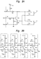
Fig. 2A shows an example of a circuit
construction of a control signal input/output section
which enables the control signal to a plurality of
equipment to be transmitted as mentioned above. An
input signal from an output port (not shown) of a
microcomputer of the A/V equipment is supplied to a
terminal 14. The terminal 14 is connected to a base of
a transistor TR1 through a resistor R2. A resistor R3
is connected between the base of the transistor TR1 and
a grounding terminal 15. An emitter of the transistor
TR1 is connected to the grounding terminal 15 through a
resistor R4 and is also connected to contact terminals
10b and llb of terminals 10 and 11, respectively. An
input is supplied to an input port (not shown) of the
microcomputer through a terminal 12. A resistor R1 is
connected between the terminal 12 and a power source
terminal 13. The terminal 12 is connected to an anode
of a diode D1. A cathode of the diode D1 is connected
to a collector of the transistor TR1 and is also
connected to the contact terminals 10a and lla of the
terminals 10 and 11, respectively.
The control signal input section is provided
for each A/V equipment and the terminals 10 and 11 of
each A/V equipment are mutually connected. As shown in
Fig. 2B, when a plurality of such circuits are
connected by the terminals 10 and 11, they can be
considered as an OR circuit in which the transistor TR1
of each circuit is used as a switch. In this case, a
signal at the "L" level is supplied as an initial state
to the terminal 14 of each circuit. At this time, a
signal at the "H" level is outputted to the terminal 11
of each circuit. In any one of the circuits, by
supplying the signal at the "H" level to the terminal
11, the level at the terminal 11 of each circuit can be
set to the "L" level.
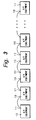
Since such a circuit is used, a plurality of
A/V equipment can be serially connected. That is, as
shown in Fig. 3, by mutually connecting the terminal 10
or 11 provided for each equipment to the terminal 10 or
11 of the other equipment, a construction shown in Fig.
2B mentioned above is realized. The control signal can
be transmitted from any one of the connected equipment
and any equipment can receive the transmitted signal.
According to this construction, the number of equipment
which are connected by a serial chain is not limited.
Actually, the number of equipment which can
be connected is limited by a factor such as a capacity
of a transmission line which is used for connection or
the like.
Fig. 4 shows an example of a transferring
method of a data signal among the A/V equipment
according to the embodiment. As mentioned above, since
the control signal input/output section according to
the embodiment is constructed so as to form an OR
circuit as a whole, the signal at the "L" level is
outputted as data for the signal at the "H" level which
is set to be default. In this example, the data is
classified depending on a length of interval of the "L"
level. In this data that is transferred as serial
data, a start bit indicates the start of data
transmission. Bit data is expressed by an on bit. The
on bit of a long interval indicates "1" and the on bit
of a short interval indicates "0". The bit data is
separated by an off bit at the "H" level. An example
of a length of interval of each bit is shown below.
The above values are not limited to such an
example but a length of interval corresponding to each
data can be also set to another length. It is
preferable to set the length in correspondence to a
communicating speed.
The data is constructed by setting eight
bits, namely, one byte to a minimum unit and is
transferred. Fig. 5 shows an example of a data
construction. First one byte indicates a control code.
The control code shows a name of connected A/V
equipment and also indicates a distinction about
whether the data is instruction data to the equipment
or mode data from the equipment. For instance, in the
foregoing example of Fig. 1, when the data signal to be
transferred is an instruction to the CD player 2, the
control code is set to "90". When it is the data that
is transmitted from the CD player 2 and indicates the
mode of the CD player 2, the control code is set to "98".
Although a data size of the above data is not
particularly limited, actually, it is preferable to set
it to about 16 bytes in consideration of a point such
as a transfer speed or the like.
In the above construction, when the signals
are transmitted at the same timing from a plurality of
equipment, there is a possibility such that a conflict
of the signals occurs and erroneous data is transmitted
or received. For example, when the off bit and the on
bit are transmitted at the same timing from different
equipment, the off bit at the "H" level is used as an
on bit at the "L" level. In the circuit, the signal
supplied from the terminal 14 is inverted at the
terminal 12 and is detected. By using such a nature
and by monitoring the own data signal in each
equipment, the conflict can be detected. When the
conflict is detected, for example, the data signal is
again transmitted after a predetermined time interval
is delayed.
Fig. 6 shows an example of a construction of
an A/V system according to the embodiment and this is
an example in which an A/V amplifier 20 and a CD
changer 30 are connected through the terminal 10 or 11.
A monitor 40 to display a video image is connected to
the A/V amplifier 20. A plurality of (for example,
200) CDs can be enclosed in the CD changer 30. For
explanation, two going and returning systems are shown
as signal paths between terminals 10 or 11 in the
diagram. To avoid complexity, portions such as an
audio signal system and the like which are not directly
concerned with the present invention are omitted.
In the A/V amplifier 20, a microcomputer 21
is made up of, for instance, a microprocessor and a
necessary memory such as RAM or ROM. The microcomputer
21 has a display unit 25 for converting character data
or predetermined control data into an image signal that
can be displayed by the monitor 40. Further, although
not shown, the foregoing control signal input/output
section shown in Fig. 2A exists between the
microcomputer 21 and the terminals 10 and 11. The
control signal supplied from the terminal 10 or 11 is
supplied to the microcomputer 21 through the control
signal input/output section.
A cursor signal is formed in the
microcomputer 21. The cursor signal assists the user
when he designates coordinates on a screen of the
monitor 40. For example, a shape of hand or an arrow
which is pointed out is displayed on the monitor 40.
The cursor signal is supplied to one input terminal of
an image synthesizing circuit 22.
In the microcomputer 21, image data based on
data stored in a memory 23 is formed. The image data
is converted into an image signal by the display unit
25. The image signal is supplied to one input terminal
of a switching circuit 24 whose selection is controlled
by a control signal that is outputted from the
microcomputer 21. An output of the switching circuit
24 is supplied to the other input terminal of the image
synthesizing circuit 22. The image signals supplied to
one and the other input terminals are synthesized by
the image synthesizing circuit 22. The synthetic image
signal is supplied to the monitor 40 and is displayed.
The image synthesis which is performed in the
image synthesizing circuit 22 is executed so that two
picture planes will not influence each display using an
existing technique. For this purpose, in the synthetic
image that is obtained by the image synthesizing
circuit 22, the cursor can freely move in the picture
plane.
The A/V amplifier 20 can be remote
controlled. Although not shown, such a remote control
is realized by a method whereby, for example, the
amplifier 20 has a photosensing unit of an infrared
signal and an infrared signal is transmitted to the
photosensing unit by a remote control commander
(hereinafter, abbreviated to a "remocon") which can
modulate a control command for the amplifier 20 and can
transmit a modulated signal as an infrared signal.
When the infrared signal is received by the A/V
amplifier 20, the signal is analyzed by the
microcomputer 21 of the A/V amplifier 20. The
amplifier 20 is controlled on the basis of an analysis
result.
A direction sensing device by, for example, a
gyro mechanism or the like is built in the remocon.
Movement data is formed on the basis of direction data
detected by the direction sensing device. In this
case, when a valid range of the screen of the monitor
40 exists in the direction where the remocon directs,
actual coordinates of the screen of the monitor 40 are
set to coordinate information. The movement data is
formed on the basis of the coordinate information. The
cursor is moved on the screen of the monitor 40 on the
basis of the movement data. When a predetermined
operation is performed for the remocon by the user, the
function shown at the position on the screen of the
monitor 40 where the cursor exists is designated and
the designated function is realized.
The signal which is transmitted from the
remocon is not limited to the foregoing infrared
signal. For example, a frequency modulated radio wave
can be used as such a signal. In case of using a radio
wave, the signal can be detected in a range wider than
that in case of using the infrared signal.
The formation of the movement data based on
the instruction of the remocon is not limited to the
foregoing method using the direction sensing device
built in the remocon. For example, it is also possible
to provide direction keys corresponding to the upper,
lower, left, and right directions for the remocon and
to form the movement data on the basis of the operation
by the direction keys. The formation of the movement
data can be also performed on the basis of the
operation of what is called a 4-directions-key,
joystick, or the like.
In the CD changer 30, the foregoing control
signal input/output section shown in Fig. 2A exists
between a microcomputer 31 comprising a microprocessor,
an RAM, an ROM, and the like and terminals 10' and 11'.
The control signal supplied from the terminal 10 or 11
is supplied to the microcomputer 31 through the control
signal input/output section.
In a manner similar to the foregoing
microcomputer 21, the microcomputer 31 has a display
unit 33 for converting character data or predetermined
control data into an image signal which can be
displayed by the monitor 40. Image data based on the
data stored in a memory 32 is formed in the
microcomputer 31. The image data is converted into an
image signal by the display unit 33 and is supplied as
a video output to the A/V amplifier 20. In the
amplifier 20, the image signal is supplied to the other
input terminal of the switching circuit 24.
In the CD changer 30, a mechanical unit 34 to
actually exchange or drive the CD is controlled by a
control signal from the microcomputer 31.
An example of the operation of the A/V
amplifier 20 will now be described with the above
construction. It is now assumed that in the function
of the A/V amplifier 20, the path to which the CD
changer 30 is connected is selected. As mentioned
above, a video output from the CD changer 30 is
supplied to the amplifier 20 and is selected as an
input function.
In such a connecting state, a power supply of
the CD changer 30 is turned on preliminarily or
simultaneously with a power supply of the A/V amplifier
20 is turned on. The above power-on operation is
realized, for example, by providing power supplying
means which is interlocked with the A/V amplifier 20
for the A/V amplifier 20 and by supplying a power
source of the CD changer 30 from the power supplying
means. When the power source of each of the connected
A/V equipment is turned on, a data signal including
information (model data) indicative of each equipment
is transmitted from the terminal 10 or 11 of each
equipment. When the model data signal of each of the
connected equipment is received by the A/V amplifier
20, the equipment connected to the amplifier 20 is
discriminated.
For example, the model data signal indicative
of the CD changer 30 is generated from the CD changer
30. When the model data signal is received by the A/V
amplifier 30, a fact that the CD changer 30 is
connected to the A/V amplifier 20 is discriminated.
Now, information indicating that, for instance, the CD
changer 30 has the video output is allowed to be
included in the model data signal, thereby enabling the
A/V amplifier 20 to recognize such a fact.
Fig. 7 shows an example of the first display
picture plane on the monitor 40. At this time point,
in the switching circuit 24 of the A/V amplifier 20
shown in Fig. 6, one input terminal as a microcomputer
21 side is selected. The display picture plane is
formed by the microcomputer 21 on the basis of the
information stored in the memory 23. The image
supplied to the image synthesizing circuit 22 through
the switching circuit 24 and the cursor formed by the
microcomputer 21 are synthesized in the image
synthesizing circuit 22. The synthetic image signal is
supplied to the monitor 40, so that an image is
displayed.
As shown in Fig. 7, various control displays
are arranged on a picture plane 50. A display arranged
at the right edge of the picture plane 50 is a sound
volume control display. A control display is arranged
to two stages at the lower edge of the picture plane
50. The display at the lower edge is a control display
that is peculiar to the equipment selected by the
function in the A/V amplifier 20. In the example in
which the CD changer 30 is selected, a control display
regarding the selection of the CD is performed at the
upper stage, and a control display regarding the
reproduction of the selected CD is performed at the
lower stage, respectively.
A control display to display a menu for
switching the function of the amplifier 20 is arranged
at the upper edge of the picture plane 50 and a control
display to display a menu for audio control is arranged
at the left edge, respectively. An image which is
supplied from the equipment designated by the function
can be displayed in the center portion of the picture
plane 50. The display in the center portion will be
described hereinlater.
As shown in Fig. 7, a cursor 51 is displayed
at an arbitrary position on the picture plane. The
cursor 51 is moved on the basis of the movement data
which is obtained by the foregoing method and is
overlaid to a desired control display of the picture
plane 50. By performing a predetermined operation for
the remocon, for example, by depressing an "ENTER" key
provided for the remocon, a control shown in the
control display on which the cursor 51 is overlaid is
selected.
On the picture plane 50, when "LIST" shown at
the lower stage is designated, the operating mode is
switched and the display of the picture plane 50 is set
to contents shown in Fig. 8 or 9. The displays of
Figs. 8 and 9 are based on the image signal which is
supplied from the CD changer 30. That is, when "LIST"
is selected, the control signal including a mode
switching code is transmitted from the A/V amplifier 20
to the CD changer 30 by the control of the
microcomputer 21. In the CD changer 30, an image
signal is formed by the microcomputer 31 on the basis
of the mode switching code and is outputted.
On the other hand, on the A/V amplifier 20
side, an input terminal of the switching circuit 24 is
switched from one input terminal to the other input
terminal as a CD changer 30 side by the control of the
microcomputer 21. Thus, the image signal outputted
from the microcomputer 31 is supplied to the image
synthesizing circuit 22 through the switching circuit
24. In the image synthesizing circuit 22, the image
signal and the cursor signal supplied from the
microcomputer 21 are synthesized and displayed on the
monitor 40.
In Figs. 8 and 9, for example, in Fig. 8, a
list of the titles of the CDs enclosed in the CD
changer 30 is displayed (picture plane 52). In Fig. 9,
a list of music pieces recorded in the selected CD is
displayed (picture plane 54). In Fig. 8, when a
predetermined CD title is selected, the operating mode
is further switched and the display of the picture
plane 52 is shifted to a display of a picture plane 54
of Fig. 9.
As mentioned above, when the display is
performed on the basis of the image signal supplied
from the CD changer 30, the control signal which is
supplied from the A/V amplifier 20 to the CD changer 30
is made up of coordinate data of the cursor 51 at a
position where the "ENTER" key was depressed. The
coordinate data is supplied as a control signal to the
microcomputer 31 of the CD changer 30 from the
microcomputer 21 through the terminal 10 or 11 and
terminal 10' or 11'.
By supplying the coordinate data from the A/V
amplifier 20 to the CD changer 30, the picture plane
control is shifted from the A/V amplifier 20 to the CD
changer 30. That is, in the microcomputer 31, the
image data (image data to display the foregoing picture
plane 52 or 54) supplied to the A/V amplifier 20 and
the supplied coordinate data are made correspond and
the control based on the control display displayed on
the picture plane 52 or 54 is performed.
That is, by the operation of the remocon by
the user, for example, the cursor 51 is matched with
the control display displayed on the picture plane 52
and, for instance, the "ENTER" button is depressed. An
infrared signal including data indicative of the
position of the cursor is transmitted from the remocon
to the infrared photosensing unit of the A/V amplifier
20. This signal is analyzed by the microcomputer 21.
On the basis of the obtained coordinate data of the
cursor 51, a cursor image signal is formed in the
microcomputer 21. The cursor image signal and the
image signal supplied from the CD changer 30 are
synthesized by the image synthesizing circuit 22 and
the picture plane 52 is formed and displayed on the
monitor 40. The coordinate data of the cursor 51 is
also supplied to the microcomputer 31 of the CD changer
30.
In the microcomputer 31, the contents of the
control are discriminated on the basis of the supplied
coordinate data and the image data for the picture
plane 52. The image data is formed on the basis of the
contents of the control. For example, the title data
of the CDs which has previously been stored in the
memory 32 is read out and the image data is formed by
the microcomputer 31 on the basis of the title data
which was read out. The image data is converted into
an image signal by the display unit 33 and is supplied
as video output to the A/V amplifier 20. As mentioned
above, the control of the CD changer 30 by the remocon
of the A/V amplifier 20 is performed.
For example, a list of the titles of the CDs
enclosed in the CD changer 30 is displayed on the
picture plane 52 shown in Fig. 8. The user can select
a desired CD from the displayed title list by the
operation of the remocon. For example, although 200
CDs can be enclosed in the CD changer 30, for instance,
ten titles can be displayed in a lump on the picture
plane 52. On the picture plane 52, the other titles
can be sequentially displayed by operating a scroll bar
53 provided at the right edge of the picture plane 52
by using the remocon. The above display can be
performed by a method whereby the title data of the CDs
is sequentially read out from the memory 32 in the CD
changer 30 in association with the operation of the
scroll bar 53 by the remocon.
The selection of the CD based on the picture
plane 52 is also similarly performed. For example, on
the picture plane 52, a CD title display line where the
cursor exists is emphasized by an inversion display or
the like. By depressing the "ENTER" button of the
remocon in the line on which a desired CD title is
displayed, the CD is selected. The music title data of
the CDs enclosed in the CD changer 30 can be
preliminarily stored in the memory 32. When the CD is
selected, the music title data of the selected CD is
read out from the memory 32. On the basis of the music
title data which was read out, image data for
displaying the picture plane 54 is produced in the
microcomputer 31 and is converted into the image signal
by the display unit 33. The image signal is supplied
as a video output to the A/V amplifier 20. By
selecting a desired one of the music titles displayed
on the picture plane 54, the CD can be reproduced.
An "EXIT" button 55 is provided for the
picture planes 52 and 54 which are displayed on the
basis of the video output supplied from the CD changer
30. By designating the button 55, the screen can be
returned to the previous picture plane. For example,
when the "EXIT" button 55 is designated on the picture
plane 54, the picture plane 52 is displayed. When the
button 55 is designated on the picture plane 52, the
control is shifted from the CD changer 30 to the A/V
amplifier 20. Such a shift is performed by generating
a predetermined control signal from the microcomputer
31 to the microcomputer 21. On the basis of the
control signal, the switching circuit 24 is switched
and the picture plane 50 formed by the microcomputer 31
is displayed on the monitor 40.
According to the embodiment, two kinds of
instruction codes to instruct different controls exist
in the control signal which is generated from the A/V
amplifier 20 to the CD changer 30. In the instruction
codes, for example, the first code is set to "903A" and
the second code is set to "9039".
Among them, the first code is used in, for
example, a case where the cursor can be freely moved on
each picture plane as mentioned above. In this case,
since the cursor can freely move in the picture plane,
for example, only when the "ENTER" key is depressed in
the remocon, the coordinate data of the cursor at that
time is transmitted from the A/V amplifier 20 to the CD
changer 30. A predetermined control is performed to
the CD changer 30 in response to the coordinate data.
The cursor display is formed on the A/V amplifier 20
side.
Since there is a limitation in the transfer
speed of the control signal, if the movement data is
transmitted from the A/V amplifier 20 to the CD changer
30 in a real-time manner, a time lag occurs between the
cursor display in the picture plane and the operation
of the remocon. Therefore, it is necessary to avoid a
deterioration in operability. Thus, if the transfer
speed of the control signal is sufficiently high, the
control of the cursor display can be also performed on
the CD changer 30 side.
On the other hand, the second code is used in
the case where, for example, the cursor is moved in
each picture plane every control display. This state
corresponds to a case where the remocon of the A/V
amplifier 20 has the upper, lower, left, and right
direction keys or a cross-key as mentioned above. In
this case, after the switching circuit 24 was switched
to the CD changer 30 side, each time the direction key
of the remocon of the A/V amplifier 20 is depressed, an
instruction code so as to perform the cursor movement
corresponding to the depressed key is transmitted as
cursor movement data from the A/V amplifier 20 to the
CD changer 30. The display of the cursor movement due
to the movement data is executed on the CD changer 30
side.
When the cursor is moved for the target
control display, in the remocon of the A/V amplifier
20, for example, by depressing the "ENTER" key, the
selection is performed. In the CD changer 30, the
control corresponding to the "ENTER" key is executed.
Even in any of the foregoing first and second
instruction codes, for example, by selecting the "EXIT"
button 55 in the picture plane 52, the operating mode
is switched and the picture plane control can be
returned from the CD changer 30 to the A/V amplifier
20. The instruction code is transmitted from the CD
changer 30 to the A/V amplifier 20. In the A/V
amplifier 20, the switching circuit 24 is switched in
accordance with the instruction code.
In the above description, although the CD
changer 30 can output the video image, the invention is
not limited to such an example. That is, the invention
can be also applied to a case where the other A/V
equipment which is connected to the A/V amplifier 20
doesn't have the video output. In this case,
information of the equipment to be connected is
previously recorded and when, for example, the forgoing
"LIST" key is selected, the information of the
corresponding equipment is read out from the memory 23.
An image signal is formed on the basis of the read-out
information and is displayed on the monitor 40. As
shown in an example of Fig. 10, the above display is
performed to the center portion of the picture plane 50
shown in Fig. 7 mentioned above. The user can select
the CD title by, for example, the remocon operation on
the basis of the display of the picture plane 50.
In case of the above example, equipment which
is connected to the A/V amplifier 20 cannot be
specified. Therefore, in the memory 23, since it is
difficult to assure an enough area for each of the
connected A/V equipment, information of an enough
amount as compared with the case where the connecting
equipment side has the video output means cannot be
displayed.
As described above, according to the
invention, in the A/V system such that a number of A/V
equipment are connected, the control signal of the
connected A/V equipment can be transferred to each
equipment and, in association with the selection of the
equipment, the control is shifted to the relevant
equipment, there is an effect such that the user can
perform the operation of each A/V equipment without
changing and grasping the different remocon.
According to the invention, since the
equipment can be controlled on the control picture
plane which the connected equipment has, there are
effects such that the maximum information of the
equipment can be obtained and the operability is
improved.
Having described specific preferred
embodiments of the present invention with reference to
the accompanying drawings, it is to be understood that
the invention is not limited to those precise
embodiments, and that various changes and modifications
may be effected therein by one skilled in the art
without departing from the scope or the spirit of the
invention as defined in the appended claims.