EP0843315A1 - Terminal device and memory device-fastening mechanism - Google Patents
Terminal device and memory device-fastening mechanism Download PDFInfo
- Publication number
- EP0843315A1 EP0843315A1 EP97309159A EP97309159A EP0843315A1 EP 0843315 A1 EP0843315 A1 EP 0843315A1 EP 97309159 A EP97309159 A EP 97309159A EP 97309159 A EP97309159 A EP 97309159A EP 0843315 A1 EP0843315 A1 EP 0843315A1
- Authority
- EP
- European Patent Office
- Prior art keywords
- storage device
- frame
- disk
- fastening mechanism
- base plate
- Prior art date
- Legal status (The legal status is an assumption and is not a legal conclusion. Google has not performed a legal analysis and makes no representation as to the accuracy of the status listed.)
- Withdrawn
Links
Images









Classifications
-
- G—PHYSICS
- G11—INFORMATION STORAGE
- G11B—INFORMATION STORAGE BASED ON RELATIVE MOVEMENT BETWEEN RECORD CARRIER AND TRANSDUCER
- G11B33/00—Constructional parts, details or accessories not provided for in the other groups of this subclass
- G11B33/12—Disposition of constructional parts in the apparatus, e.g. of power supply, of modules
- G11B33/121—Disposition of constructional parts in the apparatus, e.g. of power supply, of modules the apparatus comprising a single recording/reproducing device
- G11B33/123—Mounting arrangements of constructional parts onto a chassis
- G11B33/124—Mounting arrangements of constructional parts onto a chassis of the single recording/reproducing device, e.g. disk drive, onto a chassis
-
- G—PHYSICS
- G06—COMPUTING OR CALCULATING; COUNTING
- G06F—ELECTRIC DIGITAL DATA PROCESSING
- G06F1/00—Details not covered by groups G06F3/00 - G06F13/00 and G06F21/00
- G06F1/16—Constructional details or arrangements
- G06F1/18—Packaging or power distribution
- G06F1/183—Internal mounting support structures, e.g. for supporting printed circuit boards
- G06F1/184—Mounting of motherboards
-
- G—PHYSICS
- G06—COMPUTING OR CALCULATING; COUNTING
- G06F—ELECTRIC DIGITAL DATA PROCESSING
- G06F1/00—Details not covered by groups G06F3/00 - G06F13/00 and G06F21/00
- G06F1/16—Constructional details or arrangements
- G06F1/18—Packaging or power distribution
- G06F1/183—Internal mounting support structures, e.g. for supporting printed circuit boards
- G06F1/187—Mounting of fixed or removable disk drives
-
- G—PHYSICS
- G11—INFORMATION STORAGE
- G11B—INFORMATION STORAGE BASED ON RELATIVE MOVEMENT BETWEEN RECORD CARRIER AND TRANSDUCER
- G11B33/00—Constructional parts, details or accessories not provided for in the other groups of this subclass
- G11B33/02—Cabinets; Cases; Stands; Disposition of apparatus therein or thereon
- G11B33/08—Insulation or absorption of undesired vibrations or sounds
-
- G—PHYSICS
- G11—INFORMATION STORAGE
- G11B—INFORMATION STORAGE BASED ON RELATIVE MOVEMENT BETWEEN RECORD CARRIER AND TRANSDUCER
- G11B33/00—Constructional parts, details or accessories not provided for in the other groups of this subclass
- G11B33/12—Disposition of constructional parts in the apparatus, e.g. of power supply, of modules
- G11B33/125—Disposition of constructional parts in the apparatus, e.g. of power supply, of modules the apparatus comprising a plurality of recording/reproducing devices, e.g. modular arrangements, arrays of disc drives
- G11B33/127—Mounting arrangements of constructional parts onto a chassis
- G11B33/128—Mounting arrangements of constructional parts onto a chassis of the plurality of recording/reproducing devices, e.g. disk drives, onto a chassis
Definitions
- the present invention relates to a terminal device to which a storage device is mounted, and a storage device fastening mechanism for fastening the storage device. Particularly, it relates to a terminal device which generates vibration during operation, such as a POS (Point-of-Sales) terminal device in which the vibration accompanies the opening/shutting operation of a drawer.
- POS Point-of-Sales
- a magnetic storage device such as a hard disk drive (HDD) or a floppy disk drive (FDD).
- HDD hard disk drive
- FDD floppy disk drive
- a file disk reads information recorded on a magnetic disk and records information thereon, while rotating the magnetic disk by a motor, using a magnetic head attached to an arm which is driven to rotate about a pivot.
- the magnetic head may deviate from the proper position causing incorrect reading/recording of information or touching a surface of the magnetic disk, thereby damaging the information recorded thereon.
- a POS terminal device will be described below as an example of a terminal device which frequently generates vibration.
- the POS terminal device has a drawer for holding cash therein to transfer the same between customers and the operator.
- the drawer is normally closed, but temporarily made to open for the purpose of cash delivery/acceptance when a sale is completed and is then shut again by the operator.
- a relatively large vibration occurs in the POS terminal device. Particularly, when the drawer is opened, the vibration is considerable because a spring force is used for this purpose.
- a disk file device is provided in the POS device. Since the disk file device is often accommodated in a controller section provided on the drawer, a read error on the disk or the like may frequently occur due to shock caused by the opening/shutting of the drawer.
- Such a problem is not limited to POS terminal devices, but is common to generally-used personal computers or others if they are located in the vicinity of a vibration source or in an environment wherein a relatively intense vibration is liable to be transmitted to the computer body. Under the circumstances, the disk device in the personal computer may be broken as in the POS terminal device.
- FIGs. 22A and 22B of the accompanying drawings a previously-proposed structure for securing a magnetic disk device to a terminal device is illustrated.
- the magnetic disk device is not directly attached to a base plate of a terminal device, but is first attached to a frame which in turn is fastened to the base plate.
- the frame consists of a frame B for mounting the magnetic disk device and a frame A attached to the frame B as a cover.
- a steel collar spacer is inserted into a central hole of a grommet made of an elastic material such as rubber, which in turn is fitted into a screw hole of the frame B.
- the magnet disk device is placed on the grommet and screw-fastened. Since the grommet is capable of absorbing shock by its elasticity, it is possible to mitigate shock caused by the opening/shutting of a drawer and thus reduce the magnitude of shock transmitted to the magnetic disk device.
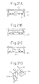
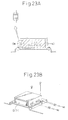
- Figs. 23A and 23B of the accompanying drawings illustrate another previously-proposed structure for fastening a magentic disk device.
- the magnetic disk device is attached to a frame corresponding to the frame A shown in Figs. 22A and 22B.
- the frame has screw holes for fastening the magnetic disk device on the opposite side surfaces thereof. Also, in the structure shown in Figs. 23A and 23B, since the magnetic disk device is attached via the grommets and the collar spacers, it is possible to minimize vibration directly transmitted to the magnetic disk device.
- the above method for mounting the magnet disk device to the frame requires the use of a metallic plate, which results in an increase in the frame cost.
- a terminal device comprising a frame for detachably mounting an information storage device for storing information, and a base plate for detachably mounting the frame for mounting the storage device.
- the storage device mounting frame is preferably made of a flexible member.
- side engaging portions may be provided on the bottom surface of the storage device mounting frame, to be inserted into mating engaging portions provided on the base plate, and the storage device mounting frame may be provided with means for limiting the movement of the base plate in the inserting direction of the storage device mounting frame into the base plate, when the frame side engaging portions are engaged with the base plate side engaging portions, so that the storage device mounting frame is fastened to the base plate.
- the attachment/detachment of the frame to the terminal device can be simplified because no screws are used for fastening the frame to the base plate, which can allow a reduction in the number of parts.
- a storage device fastening mechanism for detachably amounting a storage device for storing information
- the fastening mechanism is integrally formed of a flexible member, and has storage device fixtures on the bottom surface thereof, for supporting the bottom surface of the information storage device placed thereon.
- the storage device fixture may have a hole for a screw so that the storage device is fastened to the storage device fixture by the screw.
- the storage device fastening mechanism may further comprise a retainer for retaining the opposite sides of the storage device to be mounted, the retainer being provided with an engaging portion to be engageable with a member for holding the upper side of the storage device.
- the storage device fastening mechanism According to such a storage device fastening mechanism, external shock can be absorbed because the storage device fixture has elasticity, whereby the shock or vibration directly transmitted to the storage device may be reduced. Also, the storage device may be easily attached to or detached from the storage device fastening mechanism by such a storage device fixture and retainer.
- the storage device fastening mechanism preferably further comprises a first storage device fixture for fastening a first storage device, and a second storage device fixture for fastening a second storage device having a size different from that of the first storage device. According to this structure, it is possible to mount storage devices having various sizes to a common storage device fastening mechanism.
- An area of the bottom surface of the storage device fastening mechanism in which the first storage device fixture is provided and that in which the second storage device fixture is provided may be at different levels from each other. Thereby, it is possible to show the operator a position of a proper storage fixture at which a corresponding storage device is to be mounted.
- An area in the bottom surface of the storage device fastening mechanism, in which one of the first and second fixtures corresponding to the storage device of a smaller size is provided, may be at a level lower than that for the other storage device.
- this mechanism further comprises a storage device retainer for holding a side of the storage device; the storage device retainer having a mounting portion for mounting a plate-like member for pressing the upper surface of the storage device secured to the storage device fastening mechanism.
- Fig. 1 illustrates a POS terminal to which is applied a fixture mechanism for a memory device embodying an aspect of the present invention.
- the memory device is a magnetic disk device (an HDD or an FDD).
- the POS terminal is roughly divided into a controller section 1 and a drawer section 2.
- the controller section 1 has a control device (such as a CPU) for supervising various processes conducted by the POS terminal, and carrying a magnetic disk device (corresponding to a disk part in the drawing) in the interior thereof.
- a keyboard 5 for inputting information
- a display 4 for displaying information
- a printer 6 for printing receipts and journals.
- the drawer section 2 is provided for keeping cash to be transferred from/to customers.
- the drawer section 2 has a drawer 3 which is opened and closed when the cash is transferred from/to the customer. Since the drawer 3 is opened and closed relatively frequently, and generates vibration at that time, it is necessary to prevent such vibration from reaching the magnetic disk device particularly when the same is in operation.
- a fixture mechanism for a magnetic disk device according to this embodiment will be described below.
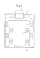
- Fig. 2 is a top view of a HDD fixture mechanism according to this embodiment (hereinafter referred to as a frame).
- Fig. 3A is a front view of the frame shown in Fig. 2;
- Fig. 3B is a back view thereof;
- Fig. 3C is a side view thereof.
- Figs. 4A, 4B, and 4C are lengthwise sectional views of the frame, respectively, wherein Fig. 4A is a view taken along line A-A in Fig. 2;
- Fig. 4B is a view taken along line B-B in Fig. 2; and
- Fig. 4C is a view taken along line C-C in Fig. 2.
- Figs. 4A is a view taken along line A-A in Fig. 2
- Fig. 4B is a view taken along line B-B in Fig. 2;
- Fig. 4C is a view taken along line C-C in Fig. 2.
- Figs. 4A
- the frame 10 is molded from a resin.
- the resin-molded frame is more advantageous in manufacturing cost than a metallic frame.
- members constituting the frame are preferably elastic and soft as described in detail later, a resin is suitable for such members.
- a metallic frame can be used instead.
- disk fixtures 12 are provided for fastening an HDD.
- the disk fixture 12a fastens a so-called 3.5 inch disk wherein a magnetic disk of 3.5 inch diameter is used
- the disk fixture 12b fastens a so-called 2.5 inch disk wherein a magnetic disk of 2.5 inch diameter is used.
- HDDs the above-mentioned two kinds of devices wherein the 2.5 inch disk is smaller in size.
- the kind of HDD to be selected may be changed in accordance with the user's demand on size, memory capacity or processing speed. It is necessary to adapt the terminal device to be capable of carrying thereon any kind of HDD selected by the user.
- the frame for carrying the HDD is preferably one kind which is adaptable to a plurality of kinds and sizes of HDD.
- the disk fixtures 12a for 3.5 inch disk are arranged at a lengthwise distance of 44.5 mm and a widthwise distance of 95.2 mm.
- the disk fixture 12b for 2.5 inch disk are arranged at a lengthwise distance of 38.1 mm and a widthwise distance of 61.8 mm. These distances are determined in accordance with the outer dimensions of the respective HDD.
- a hole is provided for fastening the magnetic disk device by a screw.
- the screw is inserted into the hole from the bottom surface of the frame 10 and screw-engaged with a threaded hole provided on the bottom surface of the HDD, whereby the HDD is fastened to the frame 10.
- the hole in the disk fixture 12 has a larger diameter than that of the screw so that the screw can freely pass therethrough.
- the disk fixture 12 is located at a position somewhat higher than the bottom surface of the frame 10. Since the disk fixture 12 is located above the bottom surface of the frame 10 such that there is a gap therebetween, it is possible to reduce the vibration directly transmitted from the bottom surface of the frame 10 to the HDD. Particularly, if the frame 10 is formed of a resin having a relatively large elasticity, the disk fixture 12 can function as a bumper using the elasticity of the resin. Thereby, the vibration applied from outside to the HDD can be absorbed by the disk fixture to some extent
- the disk fixtures 12a for a 3.5 inch disk are arranged in the peripheral area of the frame 10, and those (12b) for a 2.5 inch disk are in an inner area thereof.
- the inner area 11 of the bottom surface of the frame 10 carrying the disk fixture 12b for a 2.5 inch disk is lower than the peripheral area thereof carrying the disk fixture 12a for a 3.5 inch disk.
- a cross-section of the area 11 of the frame 10 carrying the disk fixture 12b for a 2.5 inch disk has a width of about 70 mm in the illustrated embodiment.
- the width may not be limited to this value provided it is sufficient for accommodating the 2.5 inch disk but insufficient for accommodating the 3.5 inch disk. According to this adaptation, it is possible to eliminate the erroneous mounting of a HDD onto an unsuitable disk fixture.
- engaging portions 16a are provided for attaching the frame 10 to a base plate of the terminal device described in detail later.
- engaging portions 16b are provided for attaching the frame 10 to a base plate of the terminal device. These engaging portions 16a, 16b are engageable with mating portions of the base plate as described in detail later.
- a lever 14 extends from the rear end of the frame 10, for fastening the frame 10 to the base plate. As apparent from the sectional view of the frame 10, the lever 14 has a projection of a triangular cross-section.
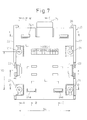
- Fig. 7 is a top view of a frame for carrying an FDD embodying the present invention. Similar to the frame shown in Fig. 2, this frame is molded in resin.
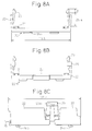
- Fig. 8A is a front view of the frame shown in Fig. 7; Fig. 8B is a back view thereof; and Fig. 8C is a side view thereof.
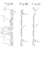
- Figs. 9A, 9B and 9C are cross-sectional views taken along lines A-A, B-B, and C-C in Fig. 7, respectively.
- Figs. 10A, 10B and 10C are cross-sectional views taken along lines D-D, E-E and F-F in Fig. 7, respectively.
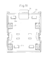
- Fig. 11 is a bottom view of the frame shown in Fig. 7.
- Fig. 7 illustrates a frame 20 for carrying an FDD device.
- the frame 20 has four disk fixtures 21 for an FDD having a similar shape to that of an HDD.
- the disk fixture 21 of the frame 20 for an FDD has a center hole for a screw as is the case of the former frame, but the frame 20 is adapted to carry and fasten an FDD even if there are no screws.
- side walls 22 are provided in the frame 20 for supporting an FDD to be carried on the frame 20, and disk side retainers 23 are provided in a generally central area of the frame 20 for retaining an FDD.
- the disk side retainer 23 has a cross-sectional shape similar to that of an upwardly-directed arrow head.
- Projected supports 26 are provided at the rear end of the frame 20 for abutting against the rear end of an FDD to be carried on the frame 20.
- the disk side retainer 23 is disposed to slightly incline inward.
- the lateral side thereof abuts to the inner side of the disk side retainer 23 to somewhat push the same aside. Due to the elasticity of the resin forming the frame 20, the disk side retainer 23 generates a force to restore the retainer inward to the original position in a state wherein an FDD is mounted, resulting in a function for supporting the lateral side of FDD.
- a notch 23a is provided in the upper end portion of the disk side retainer 23. As described in detail later, the notch 23a is used for attaching a retainer plate for pressing a top wall of an FDD mounted to the frame 20 downward.
- engaging portions 24a, 24b are provided on the bottom surface of the frame 20, for attaching the frame 20 to the base plate of the terminal device.
- a pair of hook-like engaging portions 24a are provided in the vicinity of the rear end of the frame 20. These engaging portions 24a, 24b are inserted into holes in the base plate of the terminal device to fasten the frame thereto.
- a lever 25 is provided at the rear end of the frame 20, in the same manner as for the FDD frame 10.
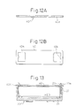
- Figs. 12A and 12B illustrate a retainer plate for fastening an FDD to the frame 20.
- the retainer plate 40 has a pair of openings 40a in the vicinity of the opposite edges thereof, respectively, each having a hook 40b at the center of the outer inside wall thereof. The distance between the pair of hooks 40b corresponds to a distance between the pair of disk side retainers 23 when the FDD is mounted on the frame 20.
- Fig. 13 illustrates a front sectional view of the frame 20 carrying an FDD with the aid of the retainer plate 40.
- a tip end of the disk side retainer 23 is inserted into the opening of the retainer plate 40.
- the hook 40b of the retainer plate 40 is engaged in the notch of the disk side retainer 23 to secure the retainer plate 40.
- the FDD is biased upward, as seen in the drawing, by the elasticity of the disk fixture 21 and the disk side retainer 23 while restricting the upward motion by the retainer plate 40, whereby the FDD can be fastened to the frame 20 without using screws. Also, it is possible to absorb the external vibration by the elasticity of the disk fixture 21 to minimize the vibration transmitted to the disk device.
- the disk device may be fastened with screws when the frame 20 is used.
- Fig. 14A is a side view of the frame carrying the disk device thereon and mounted on the base plate of the terminal device, which frame is of a type having the disk retainer on the lateral side thereof as shown in Figs. 7 to 11.
- each disk fixture has a central hole for inserting a screw.
- no screws are used for fastening the disk.
- the disk fixture 21 is shaped by bending part of the bottom wall of the frame. According to such a shape, a bumper-like function is provided due to the elasticity of the resin member.
- the frame 20 on which the disk is mounted is attached to the base plate.
- the base plate has holes for securing the engaging portions 24a, 24b provided on the frame.
- the engaging portions 24a and 24b provided in the front and rear areas of the frame 20, respectively, have a generally C-shaped cross-section so that a gap is formed for receiving the base plate therein.
- the rear end of the frame has a lever 25 (a hook for the engagement of the base plate illustrated in the drawing) so that a hook provided at the front end thereof is inserted into a hole of the base plate.
- the leftward movement of the frame 20 as seen in the drawing is limited by the engaging portions 24a, 24b, and the rightward movement is limited by the hook of the lever 25.
- the frame 20 is fastened to the base plate by these elements. In this regard, the frame 20 is easily detachable from the base plate by lifting a tab of the lever 25 to release the hook from the hole of the base plate.
- Supports 26 are provided on the front and rear ends (left and right sides in the drawing) of the frame for supporting the disk.
- the disk since the disk is not fastened by screws or others, the disk may slip down from the frame 20 if it is installed in a vertical direction.
- the supports 26 provided on the front and rear ends of the frame 20 serve to prevent the disk from slipping down from the frame in such a case.
- -the supports 26 provided on the front and rear ends of the frame as shown in Figs. 14A, 14B, and 14C are more advantageous than the embodiment shown in Fig. 7 wherein the support is provided solely at the rear end of the frame.
- the frame shown in Fig. 2 can be attached to the base plate by substantially the same mechanism described above.
- Fig. 15A illustrates a state wherein a disk is mounted on the frame 20 shown in Fig. 7.
- the disk is placed on disk fixtures 21 provided on the bottom surface of the frame 20 and the upper surface thereof is lightly pressed by a retainer plate 40 (disk presser member illustrated).
- Disk side retainers 23 are provided on the lateral sides of the frame 20, and the retainer plate 40 is mounted on the upper end portions of the disk side retainers 23.
- Fig. 15D is an enlarged illustration of the main parts of the disk side retainer 23 and the retainer plate 40.
- a hook 40b provided on the retainer plate 40 is inserted into a hole 23a provided on the side wall of the disk side retainer 23 and fixed thereto.
- Fig. 15B and Fig. 15C are front views showing how a 3.5 inch disk (HDD) and a 2.5 inch disk are mounted on the same frames 10, respectively.
- the frame 10 is the one illustrated in Fig. 2.
- the 3.5 inch disk 42 is placed on the disk fixtures 12a arranged in the peripheral area of the frame 10, and fastened to the frame 10 by screws 44 inserted from beneath the frame 10.
- the 2.5 inch disk is placed on the disk fixtures 12b arranged in the central area of the frame 10, and fastened to the frame 10 by screws 44 inserted from beneath the frame 10.
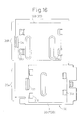
- Fig. 16 illustrates a base plate of a terminal device, to which the above-mentioned frames are fastened.
- reference numeral 30 denotes a frame; 30a a section to which the frame 20 shown in Fig. 7 is mounted; and 30b a section to which the frame 10 shown in Fig. 2 is mounted.
- the base plate is made of metal.
- the section 30a is provided with engagement holes 31a for receiving the engaging portions 24a provided on the frame 20, engagement holes 31b for receiving the engaging portion 24b, and an elongated hole 32 to receive the hook of the lever 25.
- the section 30b is provided with a base plate engaging portion 33a to receive the engaging portions 16a provided at the front end of the frame 10, and a base plate engaging portion 33b to receive the engaging portions 16b provided at the rear end of the frame 10, wherein the base plate engaging portions 33a, 33b are provided in the front and rear areas of the base plate, respectively.
- the base plate engaging portions 33a and 33b are formed by bending part of the bottom wall of the base plate upward, so that the engaging portions 16a, 16b of the frame can be inserted into gaps formed between the base plate engaging portions 33a, 33b and the bottom wall of the base plate 30, respectively.
- Figs. 17A and 17B illustrate an operation for mounting the frame 10 onto the base plate, wherein Fig. 17A is prior to the mounting of the frame 10 and Fig. 17B is after the mounting of the frame 10.
- part of the lever 14 is shown as a cross-section in Figs. 17A and 17B.
- the base plate engaging portions 33a and 33b on the base plate are formed by bending part of the bottom wall of the base plate 30.
- the engaging portions 16a and 16b are inserted first into the base plate engaging portions 33a and 33b, respectively. Thereafter, the lever 14 at the rear end of the frame 10 is inserted into an elongate hole 34 provided on the base plate 30 to secure the frame 10 to the base plate 30.
- the leftward movement of the frame 10 as seen in the drawing is limited by the base plate engaging porions 33a and 33b, and the rightward movement is limited by the hook of the lever 14 inserted into the elongate hole 34.
- Figs. 18A and 18B illustrate an operation for mounting the frame 20 onto the base plate, wherein Fig. 18A is prior to the mounting of the frame 20 and Fig. 18B is after the mounting of frame 20, respectively.
- the engaging portions 24a, 24b are inserted into the engaging holes 31a, 31b of the base plate 30, respectively.
- the lever 25 of the frame 20 is inserted into the elongate hole 32 of the base plate 30 to limit the leftward movement of the frame 20 as seen in the drawing.
- the frame can be mounted on the base plate without screws or the like. This enables one-touch frame attachment/detachment to simplify the operation for mounting the frame carrying the disk device onto the base plate.
- the frames described hereinbefore are made of a resin.
- the frame may be formed of any material provided it is elastic, such as a thin metallic sheet.
- Fig. 19 illustrates the operation for mounting a frame on a base plate according to another embodiment of the present invention.
- a frame 20' shown in Fig. 19 is capable of carrying either an HDD or an FDD.
- the frame 20' has eight disk fixtures on the bottom surface thereof. Disk fixtures 21a arranged in the peripheral area are used for mounting a 3.5 inch HDD or an FDD, while disk fixtures 21b arranged in a central area are used for mounting a 2.5 inch HDD. At the center of the respective disk fixture, a hole for a screw is provided in the same manner as in the first embodiment.
- the bottom surface of the frame 20' has two stages:- a lower stage having the disk fixtures 21b and an upper stage having the disk fixtures 21a, respectively. These disk fixtures are operated in the same manner as those of the frame 10.
- a disk side retainer 23 is provided on the lateral side of the frame 20'.
- the disk side retainer 23 shown in Fig. 19 has a shape substantially the same as that of the disk side retainer 23 shown in Fig. 7.
- An FDD and 3.5 inch HDD are mounted onto the frame 20' shown in Fig. 19 by a retainer plate 40 (disk presser member).
- the 2.5 inch HDD is fastened to the disk fixtures 21b by screws because the upper surface of HDD does not reach the retainer plate 40.
- a 3.5 inch HDD and an FDD may be fastened to the disk fixtures 21a by screws.
- supports 26a, 26b are provided, respectively. These are used for preventing a 3.5 inch HDD or the like, which is placed on the frame 20' without being fastened by screws, from slipping down from the frame 20' when the same is installed in the vertical position.
- engaging portions 24 are provided for insertion into engaging holes 31 on the base plate 30.
- Figs. 20A, 20B, and 20C are front views of the frame 20' shown in Fig. 19, on which an FDD, a 3.5 inch HDD and a 2.5 inch HDD are carried.
- FIG. 20A an FDD is carried on the frame 20'.
- Figs. 20B and 20C a 3.5 inch HDD and a 2.5 inch HDD are carried on the frame 20', respectively.
- the disk side retainer 23 is not used at all for securing an HDD at a position.
- this structure is advantageous because various disk devices can be mounted on a common frame as shown in Figs. 20A - 20C, which results in a reduction in the number of parts.
- the rightside disk side retainer 23 is eliminated from Figs. 20B and 20C for the purpose of simplicity.
- the frame of this embodiment has a two-stage bottom surface, it may alternatively have a single-stage bottom surface. In the latter case, it is possible to secure a 2.5 inch HDD without screws by a retainer plate 40.
- Figs. 21A, 21B, and 21C are front views of a frame 20" having a single-stage bottom surface, on which an HDD, an FDD or another device is mounted.
- the disk device is secured to the frame 20" with a retainer plate 40. Accordingly, no screws are necessary for fastening the disk -to the frame, which is different from any of the preceding embodiments.
- the disk device if the upper surface of an HDD or another device does not reach the retainer plate 40 or, as shown in Fig. 20C, the disk device has an excessively short width and may displace in the lateral direction, the disk device, of course, may be screw-fastened.
Landscapes
- Engineering & Computer Science (AREA)
- Theoretical Computer Science (AREA)
- Computer Hardware Design (AREA)
- Power Engineering (AREA)
- Human Computer Interaction (AREA)
- Physics & Mathematics (AREA)
- General Engineering & Computer Science (AREA)
- General Physics & Mathematics (AREA)
- Casings For Electric Apparatus (AREA)
- Connection Of Plates (AREA)
Abstract
Description
Therefore, the total number of parts can be reduced accordingly, and disk attachment/detachment becomes very easy compared with previously-proposed arrangements.
Claims (14)
- A terminal device comprising:a frame (10, 20, 20') for detachably mounting an information storage device (41, 42) for storing information, anda base plate (30) for detachably mounting the frame (10, 20, 20') for mounting the storage device.
- The terminal device of claim 1, wherein the storage device mounting frame (10, 20, 20') is made of a flexible material.
- The terminal device of claim 1 or 2, wherein frame side engaging portions (16a, 16b) are provided on the bottom surface of the storage device mounting frame (10) for insertion into mating engaging portions (33a, 33b) provided on the base plate (30), and
the storage device mounting frame (10) is provided with means (15) for limiting the movement of the base plate in the inserting direction of the storage device mounting frame (10) into the base plate (30), when the frame side engaging portions (16a, 16b) are engaged with the base plate side engaging portions (33a, 33b), so that the storage device mounting frame (10) is fastened to the base plate (30). - A storage device fastening mechanism (10, 20, 20') for detachably mounting a storage device (41, 42) for storing information, wherein
the fastening mechanism (10, 20, 20') is integrally formed of a flexible member, and has storage device fixtures (12a, 12b, 21) on the bottom surface thereof, for supporting the bottom surface of the information storage device (41, 42) placed thereon. - The storage device fastening mechanism of claim 4, wherein the storage device fixture (12a, 12b, 21) has a hole for a screw so that the storage device (41, 42) is fastened to the storage device fixture by the screw.
- The storage device fastening mechanism of claim 4 or 5, further comprising:a retainer (23) for retaining opposite sides of the storage device (41, 42) to be mounted,the retainer (23) being provided with an engaging portion (23a) for engaging with a member (40) for holding the upper side of the storage device (41, 42).
- The storage device fastening mechanism of claim 4, 5 or 6, further comprising:a first storage device fixture (12a) for fastening a first storage device (42), anda second storage device fixture (12b) for fastening a second storage device (43) having a size different from that of the first storage device (42).
- The storage device fastening mechanism of claim 7, wherein an area of the bottom surface of the storage device fastening mechanism in which the first storage device fixture (12a) is provided and that in which the second storage device fixture (12b) is provided are at different levels from each other.
- A storage device fastening mechanism (10, 20, 20') for detachably mounting a storage device (41, 42) for storing information onto a terminal device, wherein engaging portions (16a, 16b) are provided on the bottom surface thereof, to be inserted into a base plate (30) of the terminal device.
- A storage device fastening mechanism (10, 20, 20') for fastening a storage device (41, 42) to be mounted on a terminal device, comprising:a plurality of storage device fixtures (12a, 12b; 21) made of a flexible material and provided on the bottom surface of the storage device fastening mechanism (10, 20, 20'), for engaging the bottom surface of the storage device,a fastening mechanism mounting portion (16a, 16b, 33a, 33b) provided on a surface opposite to the surface on which the storage device fixtures (12a, 12b; 21) are provided, for mounting the storage device fastening mechanism (10, 20, 20') on the terminal device, anda mounting mechanism (15, 25) for fastening the storage device fastening mechanism (10, 20, 20'), when mounted on the terminal device, to the terminal device.
- The storage device fastening mechanism of claim 10, wherein the mechanism is integrally formed of a flexible member, and each storage device fixture (12a, 12b; 21) is adapted to support the bottom surface of the storage device by the elasticity of the flexible member.
- The storage device fastening mechanism of claim 10 or 11, wherein the storage device fixture comprises a first fixture (12a) for fastening a first storage device (42), and a second fixture (12b) for fastening a second storage device (43) having a different size from that of the first storage device (42).
- The storage device fastening mechanism of claim 12, wherein an area in the bottom surface of the storage device fastening mechanism (10, 20, 20'), in which one (12b) of the first and second fixtures (12a, 12b) corresponding to the storage device (43) of a smaller size is provided, is at a level lower than that (12a) for the other storage device (42).
- The storage device fastening mechanism of claim 10, 11, 12 or 13, further comprising a storage device retainer (23) for holding a side of the storage device (41, 42); the storage device retainer (23) having a mounting portion (23a) for mounting a plate-like member (40) for pressing the upper surface of the storage device (41, 42) secured to the storage device fastening mechanism (10, 20, 20').
Applications Claiming Priority (2)
| Application Number | Priority Date | Filing Date | Title |
|---|---|---|---|
| JP08300734A JP3090068B2 (en) | 1996-11-13 | 1996-11-13 | Terminal device and storage device fixing mechanism |
| JP300734/96 | 1996-11-13 |
Publications (1)
| Publication Number | Publication Date |
|---|---|
| EP0843315A1 true EP0843315A1 (en) | 1998-05-20 |
Family
ID=17888468
Family Applications (1)
| Application Number | Title | Priority Date | Filing Date |
|---|---|---|---|
| EP97309159A Withdrawn EP0843315A1 (en) | 1996-11-13 | 1997-11-13 | Terminal device and memory device-fastening mechanism |
Country Status (4)
| Country | Link |
|---|---|
| US (1) | US5943208A (en) |
| EP (1) | EP0843315A1 (en) |
| JP (1) | JP3090068B2 (en) |
| CN (1) | CN1101974C (en) |
Cited By (7)
| Publication number | Priority date | Publication date | Assignee | Title |
|---|---|---|---|---|
| GB2342759A (en) * | 1998-10-10 | 2000-04-19 | Pti Limited | Data cartridge assembly with vibration damping |
| WO2003030175A1 (en) * | 2001-10-03 | 2003-04-10 | Cabot Safety Intermediate Corporation | Hard drive disk isolation apparatus and method |
| US6925246B1 (en) | 2000-07-05 | 2005-08-02 | Steinbeck Cannery, Llc | Television recorder having a removeable hard disk drive |
| EP1462914A3 (en) * | 2003-03-28 | 2010-08-04 | Fujitsu Siemens Computers GmbH | Support for a flash memory |
| EP2472520A1 (en) * | 2010-12-31 | 2012-07-04 | Thomson Licensing | A mounting assembly for electronic component |
| CN101847037B (en) * | 2009-03-27 | 2013-05-08 | 鸿富锦精密工业(深圳)有限公司 | Hard disk fixing mechanism and electronic device with same |
| WO2013131028A1 (en) | 2012-03-01 | 2013-09-06 | Sanmina Corporation | Insertion and removal assembly for installing and removing data storage drives in an enclosure |
Families Citing this family (67)
| Publication number | Priority date | Publication date | Assignee | Title |
|---|---|---|---|---|
| US6493219B2 (en) * | 1997-12-22 | 2002-12-10 | Contec Co., Ltd. | Semiconductor memory device |
| EP0942428B1 (en) * | 1998-03-13 | 2007-05-09 | Matsushita Electric Industrial Co., Ltd. | Shock absorbing holder and information processor having same |
| KR100345875B1 (en) | 1998-09-14 | 2002-10-25 | 삼성전자 주식회사 | A portable computer |
| JP3792474B2 (en) * | 2000-03-30 | 2006-07-05 | 富士通株式会社 | Shock absorber for electronic device built-in parts |
| US6717762B1 (en) | 2000-06-09 | 2004-04-06 | Iomega Corporation | Method and apparatus for making a drive compatible with a removable cartridge |
| US6628474B1 (en) | 2000-06-09 | 2003-09-30 | Iomega Corporation | Method and apparatus for electrostatic discharge protection in a removable cartridge |
| US6633445B1 (en) | 2000-06-09 | 2003-10-14 | Iomega Corporation | Method and apparatus for electrically coupling components in a removable cartridge |
| US6624979B1 (en) | 2000-06-09 | 2003-09-23 | Iomega Corporation | Method and apparatus for parking and releasing a magnetic head |
| US20020036699A1 (en) * | 2000-09-15 | 2002-03-28 | Nicklos Carl F. | Light pipe having an improved mounting structure and method of assembling same |
| US6781782B2 (en) | 2000-12-21 | 2004-08-24 | Iomega Corporation | Method and apparatus for saving calibration parameters for a removable cartridge |
| US6675148B2 (en) | 2001-01-05 | 2004-01-06 | Digital Voice Systems, Inc. | Lossless audio coder |
| JP3857060B2 (en) * | 2001-02-09 | 2006-12-13 | 株式会社東芝 | Heating element cooling device |
| US6779067B2 (en) | 2001-05-14 | 2004-08-17 | Iomega Corporation | Method and apparatus for providing extended functionality for a bus |
| US6496362B2 (en) * | 2001-05-14 | 2002-12-17 | Iomega Corporation | Method and apparatus for protecting a hard disk drive from shock |
| US6505899B1 (en) * | 2001-05-21 | 2003-01-14 | Acorn Product Development, Inc. | Center release drive sled |
| US6901525B2 (en) | 2001-05-25 | 2005-05-31 | Iomega Corporation | Method and apparatus for managing power consumption on a bus |
| US8131389B1 (en) | 2002-02-08 | 2012-03-06 | Digital Voice Systems, Inc. | Digital audio server |
| TW525688U (en) * | 2002-07-16 | 2003-03-21 | High Tech Comp Corp | Fastener of latch lock |
| US20040105225A1 (en) * | 2002-08-14 | 2004-06-03 | Malcolm Tom Reeves | Multi-drive carrier |
| US6728109B1 (en) * | 2003-05-23 | 2004-04-27 | Cotytech Industrial Inc. | Computer drive anchoring apparatus without using screws |
| TW590267U (en) * | 2003-06-27 | 2004-06-01 | Quanta Comp Inc | Computer and its hard disc fixing apparatus |
| US6954940B2 (en) * | 2003-10-08 | 2005-10-11 | Inventec Corporation | Modularized electronic device assembly architecture |
| US20050092869A1 (en) * | 2003-10-30 | 2005-05-05 | Johnson Controls Technology Company | System and method for mounting in-vehicle electronics |
| US20050103965A1 (en) * | 2003-11-19 | 2005-05-19 | International Business Machines Corporation | Supporting adapter for portable computer system |
| JP2005157790A (en) * | 2003-11-26 | 2005-06-16 | Toshiba Corp | Electronics |
| JP2005182936A (en) * | 2003-12-19 | 2005-07-07 | Fujitsu Ltd | STORAGE DEVICE MOUNTING DEVICE, STORAGE DEVICE INTEGRATED UNIT USING THE SAME, AND ELECTRONIC DEVICE MOUNTING THE INTEGRATED UNIT |
| TWM249155U (en) * | 2003-12-31 | 2004-11-01 | Tatung Co | Detachable base of display |
| CA2490617A1 (en) | 2004-01-06 | 2005-07-06 | Darfon Electronics Corp. | Wireless input device |
| US20060198095A1 (en) * | 2005-03-03 | 2006-09-07 | Lite-On It Corp. | Self-lock assembly of a disk drive and a chassis |
| US7262958B2 (en) * | 2005-05-31 | 2007-08-28 | Dell Products L.P. | Apparatus and method for securing a component in an information handling system |
| US20070008693A1 (en) * | 2005-07-05 | 2007-01-11 | Che-Fu Yeh | Clamping structure of an electronic device |
| US20070014085A1 (en) * | 2005-07-18 | 2007-01-18 | International Business Machines Corporation | Mounting tray and release mechanism for a disk drive |
| WO2007037092A1 (en) * | 2005-09-27 | 2007-04-05 | Pioneer Corporation | Fixation member for drive device, drive unit, and information reproduction device |
| US7243844B2 (en) * | 2005-11-09 | 2007-07-17 | Dell Products L.P. | Point of sale integrator |
| US20070263349A1 (en) * | 2006-05-12 | 2007-11-15 | Chieh-Shih Yi | Fixing Support of Data Accessing Device |
| TWI321317B (en) | 2006-08-29 | 2010-03-01 | Asustek Comp Inc | Optical disc drive |
| CN101136237B (en) * | 2006-08-31 | 2011-01-12 | 华硕电脑股份有限公司 | CD drive |
| US20080094794A1 (en) * | 2006-10-20 | 2008-04-24 | Kenneth Hass | Hard drive carrier assembly having interlocking parts |
| JP4909774B2 (en) | 2007-03-19 | 2012-04-04 | 株式会社東芝 | Electronic devices and personal computers |
| US7782603B2 (en) * | 2007-03-28 | 2010-08-24 | International Business Machines Corporation | Tool-less electronic component retention |
| JP5082139B2 (en) * | 2008-02-28 | 2012-11-28 | Necインフロンティア株式会社 | Device for mounting the bracket on the base |
| JP2009259165A (en) * | 2008-04-21 | 2009-11-05 | Fujitsu Ltd | Electronic apparatus |
| JP4957733B2 (en) * | 2009-02-05 | 2012-06-20 | 株式会社デンソーウェーブ | Portable information terminal |
| JP2010257080A (en) * | 2009-04-22 | 2010-11-11 | Panasonic Corp | Information processing device |
| CN101930782B (en) * | 2009-06-26 | 2013-08-28 | 鸿富锦精密工业(深圳)有限公司 | Hard disk fixing mechanism and electronic device with the same |
| CN102033584A (en) * | 2009-09-25 | 2011-04-27 | 鸿富锦精密工业(深圳)有限公司 | Computer and hard disk bracket thereof |
| CN102549671A (en) * | 2009-10-07 | 2012-07-04 | 富士通株式会社 | Electronic component containing body and electronic apparatus |
| CN201698305U (en) * | 2010-01-18 | 2011-01-05 | 鸿富锦精密工业(深圳)有限公司 | memory fixture |
| JP2011181127A (en) * | 2010-02-26 | 2011-09-15 | Hitachi Consumer Electronics Co Ltd | Video display device |
| TWM391122U (en) * | 2010-03-15 | 2010-10-21 | Accton Tech Corp | Supporting frame for equipment |
| EP2413326B1 (en) * | 2010-07-30 | 2016-12-21 | Thomson Licensing | An electronic device comprising a removable hard disk |
| TW201228529A (en) * | 2010-12-17 | 2012-07-01 | Hon Hai Prec Ind Co Ltd | Disk drive fixing device |
| TWI438772B (en) * | 2011-07-15 | 2014-05-21 | Pegatron Corp | Vibration isolator storage module |
| JP5397433B2 (en) * | 2011-08-23 | 2014-01-22 | カシオ計算機株式会社 | Sales data processing apparatus and program |
| CN103246327A (en) * | 2012-02-06 | 2013-08-14 | 鸿富锦精密工业(深圳)有限公司 | Hardware fixing device |
| WO2013155128A1 (en) * | 2012-04-13 | 2013-10-17 | Thomson Licensing | Set top box having removable hard drive |
| US9030814B2 (en) * | 2013-06-24 | 2015-05-12 | Aic Inc. | Screwless carrying frame for data access devices |
| CN203927331U (en) * | 2014-05-28 | 2014-11-05 | 北京京东方专用显示科技有限公司 | Damping assembly and display unit for fixing display part |
| US9763353B1 (en) * | 2015-03-23 | 2017-09-12 | Amazon Technologies, Inc. | Mass storage device retainer assembly |
| US10157641B2 (en) * | 2015-04-24 | 2018-12-18 | Nec Platforms, Ltd. | HDD holding device, HDD unit, and information processing apparatus |
| TWM507142U (en) * | 2015-06-01 | 2015-08-11 | Cooler Master Technology Inc | Computer accessory holder structure and computer case thereof |
| US10281961B1 (en) * | 2016-09-13 | 2019-05-07 | ZT Group Int'l, Inc. | Hard drive tray facilitating removal and installation |
| US9898055B1 (en) * | 2016-12-18 | 2018-02-20 | Nanning Fugui Precision Industrial Co., Ltd. | Securing mechanism for data storage device |
| US10492602B2 (en) * | 2017-01-26 | 2019-12-03 | Bose Corporation | Electronics enclosure mounting |
| US10546616B2 (en) * | 2018-01-30 | 2020-01-28 | Quanta Computer Inc. | Adjustable storage device carrier |
| US11437755B2 (en) * | 2019-10-11 | 2022-09-06 | Home Theater Direct, Inc. | Controller and system |
| US11460895B2 (en) * | 2020-09-17 | 2022-10-04 | Dell Products L.P. | Thermal module assembly for a computing expansion card port of an information handling system |
Citations (6)
| Publication number | Priority date | Publication date | Assignee | Title |
|---|---|---|---|---|
| US4713714A (en) * | 1985-11-26 | 1987-12-15 | Motorola Computer Systems, Inc. | Computer peripheral shock mount for limiting motion-induced errors |
| GB2226706A (en) * | 1988-12-21 | 1990-07-04 | Research Machines Ltd | Disc drive mounting |
| GB2293051A (en) * | 1994-09-07 | 1996-03-13 | Hewlett Packard Co | Mass storage device mounting scheme |
| US5564804A (en) * | 1993-12-17 | 1996-10-15 | Silicon Graphics, Inc. | Disk drive bracket |
| US5566049A (en) * | 1995-07-07 | 1996-10-15 | At&T Global Information Solutions Company | Multidirectional independent suspension disk mounting system |
| EP0763792A1 (en) * | 1995-09-13 | 1997-03-19 | Hewlett-Packard Company | Fixing piece for data storage drive and other units |
Family Cites Families (3)
| Publication number | Priority date | Publication date | Assignee | Title |
|---|---|---|---|---|
| IL60289A0 (en) * | 1979-08-31 | 1980-09-16 | Bendix Corp | Separable electrical connector |
| JP2758283B2 (en) * | 1991-06-17 | 1998-05-28 | 株式会社東芝 | Hard disk pack detachable mechanism |
| US6108163A (en) * | 1994-10-12 | 2000-08-22 | International Business Machines Corporation | Sensitive sensor internally mounted shock for a disk drive |
-
1996
- 1996-11-13 JP JP08300734A patent/JP3090068B2/en not_active Expired - Fee Related
-
1997
- 1997-08-27 US US08/918,131 patent/US5943208A/en not_active Expired - Lifetime
- 1997-09-09 CN CN97118240A patent/CN1101974C/en not_active Expired - Fee Related
- 1997-11-13 EP EP97309159A patent/EP0843315A1/en not_active Withdrawn
Patent Citations (6)
| Publication number | Priority date | Publication date | Assignee | Title |
|---|---|---|---|---|
| US4713714A (en) * | 1985-11-26 | 1987-12-15 | Motorola Computer Systems, Inc. | Computer peripheral shock mount for limiting motion-induced errors |
| GB2226706A (en) * | 1988-12-21 | 1990-07-04 | Research Machines Ltd | Disc drive mounting |
| US5564804A (en) * | 1993-12-17 | 1996-10-15 | Silicon Graphics, Inc. | Disk drive bracket |
| GB2293051A (en) * | 1994-09-07 | 1996-03-13 | Hewlett Packard Co | Mass storage device mounting scheme |
| US5566049A (en) * | 1995-07-07 | 1996-10-15 | At&T Global Information Solutions Company | Multidirectional independent suspension disk mounting system |
| EP0763792A1 (en) * | 1995-09-13 | 1997-03-19 | Hewlett-Packard Company | Fixing piece for data storage drive and other units |
Cited By (9)
| Publication number | Priority date | Publication date | Assignee | Title |
|---|---|---|---|---|
| GB2342759A (en) * | 1998-10-10 | 2000-04-19 | Pti Limited | Data cartridge assembly with vibration damping |
| US6925246B1 (en) | 2000-07-05 | 2005-08-02 | Steinbeck Cannery, Llc | Television recorder having a removeable hard disk drive |
| US7391957B2 (en) | 2000-07-05 | 2008-06-24 | Steinbeck Cannery Llc | Television recorder having a removable hard disk drive |
| WO2003030175A1 (en) * | 2001-10-03 | 2003-04-10 | Cabot Safety Intermediate Corporation | Hard drive disk isolation apparatus and method |
| EP1462914A3 (en) * | 2003-03-28 | 2010-08-04 | Fujitsu Siemens Computers GmbH | Support for a flash memory |
| CN101847037B (en) * | 2009-03-27 | 2013-05-08 | 鸿富锦精密工业(深圳)有限公司 | Hard disk fixing mechanism and electronic device with same |
| EP2472520A1 (en) * | 2010-12-31 | 2012-07-04 | Thomson Licensing | A mounting assembly for electronic component |
| WO2013131028A1 (en) | 2012-03-01 | 2013-09-06 | Sanmina Corporation | Insertion and removal assembly for installing and removing data storage drives in an enclosure |
| EP2820502B1 (en) * | 2012-03-01 | 2017-06-14 | Sanmina Corporation | Insertion and removal assembly for installing and removing data storage drives in an enclosure |
Also Published As
| Publication number | Publication date |
|---|---|
| CN1183023A (en) | 1998-05-27 |
| JPH10144066A (en) | 1998-05-29 |
| US5943208A (en) | 1999-08-24 |
| CN1101974C (en) | 2003-02-19 |
| JP3090068B2 (en) | 2000-09-18 |
Similar Documents
| Publication | Publication Date | Title |
|---|---|---|
| US5943208A (en) | Terminal device and memory device-fastening mechanism | |
| CN101807095B (en) | Information processing apparatus | |
| US6166900A (en) | Media drive canister vibration dampner and method of dampening | |
| US20100307990A1 (en) | Retaining apparatus for data storage device | |
| US7477511B2 (en) | Removable device | |
| US20190278954A1 (en) | Pos device | |
| EP1220224A2 (en) | Hinged mounting for multiple storage drives | |
| US20060120033A1 (en) | Computer enclosure with drive bracket | |
| JP3591466B2 (en) | Disk storage medium drive | |
| US7110251B2 (en) | Mounting device for mounting expansion cards in computer enclosure | |
| US20060103272A1 (en) | Mounting assembly for computer cover | |
| US20060092603A1 (en) | Mounting assembly for cover of computer enclosure | |
| US6122164A (en) | Shock absorbing spacers for portable computer hard disc drives | |
| US6054662A (en) | Torsion enhanced return device for electronic system push button | |
| US6859362B2 (en) | Computer enclosure with slidably mounted drive bracket | |
| EP1640931B1 (en) | Merchandise sales data processing apparatus | |
| US7575203B2 (en) | Mounting apparatus for data storage device | |
| US20060290246A1 (en) | Rotating machanism of drive bracket | |
| US20070030660A1 (en) | Retention device for mounting expansion cards | |
| US5852739A (en) | Low profile plate interlock mechanism for a computer chassis | |
| US6271985B1 (en) | Flanged cover for a low profile magnetic disk apparatus | |
| US20070153471A1 (en) | Mounting apparatus for data storage device of computer system | |
| US6556528B1 (en) | Fixing device for data storage device of computer | |
| US7099113B2 (en) | Disc braking device | |
| US7364242B2 (en) | Mounting apparatus for data storage devices |
Legal Events
| Date | Code | Title | Description |
|---|---|---|---|
| PUAI | Public reference made under article 153(3) epc to a published international application that has entered the european phase |
Free format text: ORIGINAL CODE: 0009012 |
|
| AK | Designated contracting states |
Kind code of ref document: A1 Designated state(s): DE FR GB |
|
| AX | Request for extension of the european patent |
Free format text: AL;LT;LV;MK;RO;SI |
|
| 17P | Request for examination filed |
Effective date: 19980514 |
|
| AKX | Designation fees paid |
Free format text: DE FR GB |
|
| RBV | Designated contracting states (corrected) |
Designated state(s): DE FR GB |
|
| 17Q | First examination report despatched |
Effective date: 20030123 |
|
| RTI1 | Title (correction) |
Free format text: STORAGE DEVICE MOUNTING MECHANISM |
|
| GRAP | Despatch of communication of intention to grant a patent |
Free format text: ORIGINAL CODE: EPIDOSNIGR1 |
|
| STAA | Information on the status of an ep patent application or granted ep patent |
Free format text: STATUS: THE APPLICATION IS DEEMED TO BE WITHDRAWN |
|
| 18D | Application deemed to be withdrawn |
Effective date: 20050315 |