EP0843106A1 - A method for mounting a bushing in a seat of a housing, and a device and a tool for accomplishing the method - Google Patents
A method for mounting a bushing in a seat of a housing, and a device and a tool for accomplishing the method Download PDFInfo
- Publication number
- EP0843106A1 EP0843106A1 EP97850158A EP97850158A EP0843106A1 EP 0843106 A1 EP0843106 A1 EP 0843106A1 EP 97850158 A EP97850158 A EP 97850158A EP 97850158 A EP97850158 A EP 97850158A EP 0843106 A1 EP0843106 A1 EP 0843106A1
- Authority
- EP
- European Patent Office
- Prior art keywords
- seat
- housing
- low friction
- bushing
- lining
- Prior art date
- Legal status (The legal status is an assumption and is not a legal conclusion. Google has not performed a legal analysis and makes no representation as to the accuracy of the status listed.)
- Granted
Links
Images


Classifications
-
- F—MECHANICAL ENGINEERING; LIGHTING; HEATING; WEAPONS; BLASTING
- F16—ENGINEERING ELEMENTS AND UNITS; GENERAL MEASURES FOR PRODUCING AND MAINTAINING EFFECTIVE FUNCTIONING OF MACHINES OR INSTALLATIONS; THERMAL INSULATION IN GENERAL
- F16C—SHAFTS; FLEXIBLE SHAFTS; ELEMENTS OR CRANKSHAFT MECHANISMS; ROTARY BODIES OTHER THAN GEARING ELEMENTS; BEARINGS
- F16C33/00—Parts of bearings; Special methods for making bearings or parts thereof
- F16C33/02—Parts of sliding-contact bearings
- F16C33/04—Brasses; Bushes; Linings
- F16C33/06—Sliding surface mainly made of metal
- F16C33/08—Attachment of brasses, bushes or linings to the bearing housing
-
- F—MECHANICAL ENGINEERING; LIGHTING; HEATING; WEAPONS; BLASTING
- F16—ENGINEERING ELEMENTS AND UNITS; GENERAL MEASURES FOR PRODUCING AND MAINTAINING EFFECTIVE FUNCTIONING OF MACHINES OR INSTALLATIONS; THERMAL INSULATION IN GENERAL
- F16C—SHAFTS; FLEXIBLE SHAFTS; ELEMENTS OR CRANKSHAFT MECHANISMS; ROTARY BODIES OTHER THAN GEARING ELEMENTS; BEARINGS
- F16C13/00—Rolls, drums, discs, or the like; Bearings or mountings therefor
- F16C13/02—Bearings
-
- F—MECHANICAL ENGINEERING; LIGHTING; HEATING; WEAPONS; BLASTING
- F16—ENGINEERING ELEMENTS AND UNITS; GENERAL MEASURES FOR PRODUCING AND MAINTAINING EFFECTIVE FUNCTIONING OF MACHINES OR INSTALLATIONS; THERMAL INSULATION IN GENERAL
- F16C—SHAFTS; FLEXIBLE SHAFTS; ELEMENTS OR CRANKSHAFT MECHANISMS; ROTARY BODIES OTHER THAN GEARING ELEMENTS; BEARINGS
- F16C21/00—Combinations of sliding-contact bearings with ball or roller bearings, for exclusively rotary movement
-
- F—MECHANICAL ENGINEERING; LIGHTING; HEATING; WEAPONS; BLASTING
- F16—ENGINEERING ELEMENTS AND UNITS; GENERAL MEASURES FOR PRODUCING AND MAINTAINING EFFECTIVE FUNCTIONING OF MACHINES OR INSTALLATIONS; THERMAL INSULATION IN GENERAL
- F16C—SHAFTS; FLEXIBLE SHAFTS; ELEMENTS OR CRANKSHAFT MECHANISMS; ROTARY BODIES OTHER THAN GEARING ELEMENTS; BEARINGS
- F16C23/00—Bearings for exclusively rotary movement adjustable for aligning or positioning
- F16C23/10—Bearings, parts of which are eccentrically adjustable with respect to each other
-
- F—MECHANICAL ENGINEERING; LIGHTING; HEATING; WEAPONS; BLASTING
- F16—ENGINEERING ELEMENTS AND UNITS; GENERAL MEASURES FOR PRODUCING AND MAINTAINING EFFECTIVE FUNCTIONING OF MACHINES OR INSTALLATIONS; THERMAL INSULATION IN GENERAL
- F16C—SHAFTS; FLEXIBLE SHAFTS; ELEMENTS OR CRANKSHAFT MECHANISMS; ROTARY BODIES OTHER THAN GEARING ELEMENTS; BEARINGS
- F16C35/00—Rigid support of bearing units; Housings, e.g. caps, covers
- F16C35/04—Rigid support of bearing units; Housings, e.g. caps, covers in the case of ball or roller bearings
- F16C35/06—Mounting or dismounting of ball or roller bearings; Fixing them onto shaft or in housing
- F16C35/07—Fixing them on the shaft or housing with interposition of an element
- F16C35/077—Fixing them on the shaft or housing with interposition of an element between housing and outer race ring
-
- F—MECHANICAL ENGINEERING; LIGHTING; HEATING; WEAPONS; BLASTING
- F16—ENGINEERING ELEMENTS AND UNITS; GENERAL MEASURES FOR PRODUCING AND MAINTAINING EFFECTIVE FUNCTIONING OF MACHINES OR INSTALLATIONS; THERMAL INSULATION IN GENERAL
- F16C—SHAFTS; FLEXIBLE SHAFTS; ELEMENTS OR CRANKSHAFT MECHANISMS; ROTARY BODIES OTHER THAN GEARING ELEMENTS; BEARINGS
- F16C23/00—Bearings for exclusively rotary movement adjustable for aligning or positioning
- F16C23/06—Ball or roller bearings
- F16C23/08—Ball or roller bearings self-adjusting
- F16C23/082—Ball or roller bearings self-adjusting by means of at least one substantially spherical surface
- F16C23/086—Ball or roller bearings self-adjusting by means of at least one substantially spherical surface forming a track for rolling elements
-
- F—MECHANICAL ENGINEERING; LIGHTING; HEATING; WEAPONS; BLASTING
- F16—ENGINEERING ELEMENTS AND UNITS; GENERAL MEASURES FOR PRODUCING AND MAINTAINING EFFECTIVE FUNCTIONING OF MACHINES OR INSTALLATIONS; THERMAL INSULATION IN GENERAL
- F16C—SHAFTS; FLEXIBLE SHAFTS; ELEMENTS OR CRANKSHAFT MECHANISMS; ROTARY BODIES OTHER THAN GEARING ELEMENTS; BEARINGS
- F16C2322/00—Apparatus used in shaping articles
- F16C2322/12—Rolling apparatus, e.g. rolling stands, rolls
Definitions
- the present invention relates to a method for mounting a bushing in a seat of a housing, e.g. a bearing housing for allowing it thereupon to be readily displaceable in circumferential direction, or in axial direction or in a combination of circumferential and axial directions in a slip-stick free manner.
- a housing e.g. a bearing housing for allowing it thereupon to be readily displaceable in circumferential direction, or in axial direction or in a combination of circumferential and axial directions in a slip-stick free manner.
- rollers For different types of rolling mills it is common that they have at least a pair of cooperating rollers, one or more of said rollers, usually the lower one, being rotary journalled at a fixed level, whereas the other one, commonly the upper roller, is rotary journalled in a manner allowing it to be raised and lowered relative to the lower, fixed roller in order to alter the mutual distance between the rollers, for effecting adjustment of the roll-nip, i.e. the working space between the rollers at rolling operations. Such adjustment is required during the pace of the rolling operation for reducing the measure to which the blank shall be rolled.
- One method for making possible such adjustability of one of the rollers of a rolling mill is to provide the bearing housings of the adjustable (top) roller with an internal eccentric bushing, in which the outer rings of the bearings supporting the roller are mounted. Thereby it is possible to adjust the level of the adjustable (top) roller by angularly displacing the eccentric linings in their seats in the bearing housing, thereby adjusting the mutual distance between the axes of the two rollers. As stated above it is desirable that such adjustment can be effected during rolling operations, i.e. without the necessity of making the rollers cease from rotating or even without having them relieved from the often very high operating load.
- the purpose of the present invention is to propose a method for mounting a bushing in a seat of a bearing housing for allowing it thereupon to be readily displaceable in circumferential and axial directions in a slip-stick free manner, thereby solving i.a. the problems mentioned above and to provide an assembly, which gives a possibility of exact adjustment of the angular and also the axial position of the bushing, thereby also making it possible continuously to control the roll-nip in a rolling mill without such undesired results as earlier experienced and this is achived in the manner defined in the accompanying claim 1.
- the invention also refers to a device for accomplishing the method and this device is defined in claim 7.
- the invention refers to a tool for accomplising this method, and this tool is defined in the accompanying claim 9.
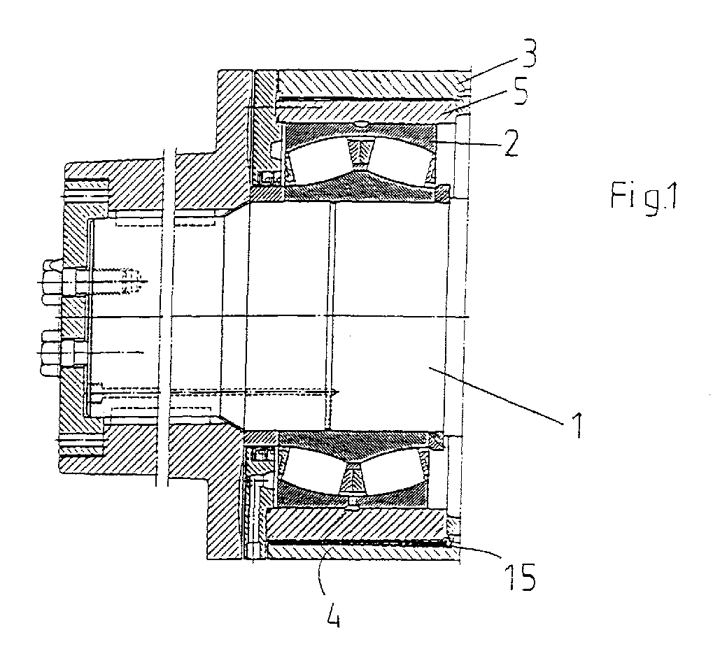
- Fig. 1 shows schematically a part of a roll journal 1 of a rolling mill, journalled in a two-row spherical roller bearing 2 positioned in a bearing housing 3.
- the bearing housing has a seat 4, and an eccentric bushing 5 interposed between the seat 4 and the outer race ring of the roller bearing 3.
- this eccentric bushing 5 which is arranged to be rotatable within the bearing housing seat, it is possible to displace the roll journal relative to the centre of the bearing housing, thereby altering the position of the roll journal and the milling roll vertically.
- the bearing has been mounted on the roll journal 1 in conventional manner and is secured axially on the roll journal with common positioning and locking means, which are no part of the invention as such and therefore will not be further described.
- spherical roller bearing shown in Fig. 1 of the drawing can be replaced for any other suitable bearing or bearing combination without departing from the inventive idea.
- the bushing to be secured in this manner is an eccentric bushing, but any type of bushing can be mounted and secured in the same manner and with the same advantages as the eccentric bushing intended for controlling roll-nip in a rolling mill.
- a layer or lining 15 having a low friction surface facing the bushing 5, and which is preferably, but not necessarily based on polytetrafluoro ethylene, PTFE, it was considered that this material must be fixedly attached to the bearing housing seat in order to give a desired effect, and it also was considered that the best manner to arrest the lining was by way of glueing. However, tests made showed that it was impossible to affix a pure PTFE layer to the bearing housing, in such a manner that it would adhere thereto.
- PTFE polytetrafluoro ethylene
- the GLYCODUR® has a sheet steel backing, which is copper plated and on its low friction surface has a porous layer of tin bronze, having a thickness of 0.2 to 0.35 mm and the pores are filled with polytetrafluoro ethylene, PTFE, together with other friction-reducing additives.
- the opposite side of the thin steel backing has a very thin tin layer covering the copper layer.
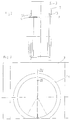
- a tool which is schematically shown in Fig.s 2 to 5, and which incorporates a tubular carrier 7, two sleeves 8, 9 positioned over said carrier 7, an inflateable member 10 (see Fig.4) positioned over the tubular carrier member 7.
- the two sleeves are positioned spaced apart over said tubular carrier with a mutual spacing corresponding to the axial length of the GLYCODUR® strip to be affixed to the bearing housing seat.
- Each one of said sleeves 8, 9 having, at least at their ends facing each other, a wall thickness, which corresponds to the thickness of the GLYCODUR® strip to be affixed to the bearing housing seat.
- the outer envelope surface of the tubular carrier member 7 has a recessed portion 11 situated between its ends and having a depth sufficient to accomodate said inflateable member 10, when this is in non-inflated condition.
- the sleeves 8,9 are positioned over the ends of the tubular carrier member 7, and are located so that they cover at least a short axial portion of the inflateable member 10 at each end of the said recessed portion 11, thereby clamping the axial end portions of said inflateable member into the recessed portion 11.
- One of said sleeves, in Figs 2, 4 and 5 the right hand sleeve 8 is equipped with a radially outwardly projecting end shoulder 12 against which a washer 13 abuts.
- a second, radially projecting washer 14 which can be detachably attached to the said sleeve 9 in a suitable manner, e.g. by means of a screw joint.
- the inflateable tubular member 10 can preferably be used a flat-wound hose, which thereby is arranged with the adjacent loops of the hose laying in close contact with each other to form a substantially continuous coil of an inflatable tubing.
- the low friction material such as e.g. GLYCODUR® is provided in form of a split ring-formed bushing 15 as shown in Fig.s 6, 7, and which is positioned upon the flat-wound hose or similar inflatable member in the space between the inwardly facing ends of the two sleeves 8,9, whereby the low friction material is positioned with the low friction surface facing the inflatable member and with the backing, i.e. the steel surface facing outwards.
- the low friction material hereby will lay flush with the upper surfaces of the axially adjoining sleeves 8,9, as the inwardly facing ends of these are of the same thickness as the low friction material.
- a plastic film layer 16 arranged to seal off the space in order to prevent glue from leaking out.
- a string of glue (not shown) is preferably positioned between the hose and the carrier member.
- the low friction material layer shall be affixed to the seat of the bearing housing, an appropriate amount of a suitable adhesive is positioned in the seat.
- the carrier 7 with the inflatable member 10 arranged in the recessed portion 11 thereof, the sealing plastic film 16, the low friction material 15, the end sleeves 8, 9 and one of the end washers, i.e. the one 13 supported by the shoulder 12 of the right hand end sleeve 8, are together as a unit pushed sideways into the interior of the housing, until the said end washer 13 with its side face comes to engagement against the outer side face of the housing 17, as intimated in Fig. 2.
- the other end washer 14 then is attached to the opposite end sleeve, i.e. in the embodiment intimated it is screwed on to it.
- the tubular member or hose 10 is inflated, whereby the flat-wound hose will expand radially from the surface of the carrier 7, thereby uniformly pressing the steel backing of the GLYCODUR® lining 15 against glue earlier applied to the internal surface of the bearing housing seat.
- glue By applying a sufficient pressure inside the hose it is possible to cause the glue to be uniformly pressed out over the bearing housing seat surface and to make the lining be in close contact against it during the time required for the glue to stiffen, thereby ascertaining that the lining is securely connected to the seat.
- the hose is provided with a hose connection 18 which is connectable to a not shown source of pressurized gas, e.g. air.
- a hose connection 18 which is connectable to a not shown source of pressurized gas, e.g. air.
- the hose connection 18 is preferably equipped with valve means operable to allow the pressure medium, such as air, to be introduced into and discharged from the hose.
- the lining 15, as shown in Fig.s 6 and 7 in cross section and side view respectively, as earlier mentioned can preferably be in form of a bushing with a longitudinal slot 19, whereby the lining can be easily adapted to the seat to which it shall be affixed in spite of any variations in seat dimensions and the like.
- this lining 15 is a strip of GLYCODUR® or the like, it comprises an external steel backing 15a and an internal low friction layer 15b,preferably based onm PTFE or another similar low friction material.
Landscapes
- Engineering & Computer Science (AREA)
- General Engineering & Computer Science (AREA)
- Mechanical Engineering (AREA)
- Rolls And Other Rotary Bodies (AREA)
- Mounting Of Bearings Or Others (AREA)
- Sliding-Contact Bearings (AREA)
- Manipulator (AREA)
- Filling Or Discharging Of Gas Storage Vessels (AREA)
Abstract
Description
Claims (9)
- A method for mounting a bushing (5) in a seat of a housing (3) for allowing it thereupon to be readily displaceable in circumferential direction or axial direction or a combination of circumferential and axial directions in a slip-stick free manner,
characterized in,
positioning a lining (15) having a low friction surface (15b) between the seat (4) of the housing (3) and said bushing (5), and affixing said lining to said seat (4) in a manner, such that the low friction surface is facing the bushing (5). - A method as claimed in claim 1,
characterized in,
using a low friction lining (15) having a low friction sliding surface (15b) based on polytetrafluoro ethylene (PTFE) and a steel backing (15a). - A method as claimed in claim 2,
characterized in
using a PTFE-based low friction lining (15) made from GLYCODUR®, modified to have a pure steel surface (15a) to be affixed to the said seat (4). - A method as claimed in anyone of claims 1-3,
characterized in,
glueing the backing side (15a) of the low friction lining (15) to the interior of the housing seat (4), and pressing during the time the adhesive is curing, the lining radially outwards against the seat surface over substantially the entire extension thereof. - A method as claimed in anyone of claims 1-4,
characterized in,using an inflatable tubular member (10), wound in flat state about a carrier (7) having a substantially cylindrical outer surface,positioning said carrier with the flat tubular member (10) positioned thereabout in the opening of the housing (3), with the surface of the tubular member inside the low friction lining (15),inflating the inflatable tubular member (10) until it engages under pressure radially against the low friction lining (15) on the side surface (15b) thereof facing away from the housing seat (4), and maintaining said pressure for a time sufficient for allowing the adhesive used to set, andthereupon releaving the pressure from the inflatable member (10) and removing it from the housing. - A method as claimed in anyone of the preceding claims,
characterized in
using an eccentric bushing (5). - A device for accomplishing the method for mounting a bushing (5) in a seat (4) of a housing (3), prefereably a bearing housing, for allowing it thereupon to be readily displaceable in circumferential and axial directions in a slip-stick free manner as claimed in claim 1,
characterized therein,
that a thin layer (15b) of a low friction material is provided in the seat (4) of the housing (3), said thin layer being interposed between the seat surface (4) and the external surface of the bushing (5). - A device as claimed in claim 7,
characterized therein,
that a joint, preferably a glue joint is provided for firmly connecting the thin low friction layer (15b) to the surface of the seat (4). - A tool for accomplishing the method according to anyone of claims 1-6,
characterized therein,
that the tool comprises a carrier (7) having an outer shape substantially corresponding to the interior shape of the housing seat (4), an inflatable tubular member (10) wound thereabout in a fiat state and with the windings in close lateral contact with each others, said tubular member being provided with at least one opening (18) for introduction and discharge of a gas such as air under pressure.
Applications Claiming Priority (2)
| Application Number | Priority Date | Filing Date | Title |
|---|---|---|---|
| SE9604181 | 1996-11-14 | ||
| SE9604181A SE510325C2 (en) | 1996-11-14 | 1996-11-14 | Procedure for mounting an eccentric bush in a seat in a roller bearing housing and a tool for carrying out the method |
Publications (2)
| Publication Number | Publication Date |
|---|---|
| EP0843106A1 true EP0843106A1 (en) | 1998-05-20 |
| EP0843106B1 EP0843106B1 (en) | 2002-12-04 |
Family
ID=20404618
Family Applications (1)
| Application Number | Title | Priority Date | Filing Date |
|---|---|---|---|
| EP97850158A Expired - Lifetime EP0843106B1 (en) | 1996-11-14 | 1997-11-13 | A method for mounting a bushing in a seat of a housing, and a device and a tool for accomplishing the method |
Country Status (5)
| Country | Link |
|---|---|
| EP (1) | EP0843106B1 (en) |
| JP (1) | JP2915384B2 (en) |
| CN (1) | CN1079919C (en) |
| DE (1) | DE69717592T2 (en) |
| SE (1) | SE510325C2 (en) |
Cited By (5)
| Publication number | Priority date | Publication date | Assignee | Title |
|---|---|---|---|---|
| WO2005028889A1 (en) * | 2003-08-29 | 2005-03-31 | Rexroth Indramat Gmbh | Bearing unit for a revolving radial load |
| WO2013050876A3 (en) * | 2011-10-04 | 2013-06-13 | Corts Engineering Gmbh & Co. Kg | Oil film bearing |
| WO2014021958A1 (en) * | 2012-04-30 | 2014-02-06 | Roller Bearing Company Of America, Inc. | Hybrid bearing assembly with rolling elements and plain bearing |
| US9261132B2 (en) | 2009-04-24 | 2016-02-16 | Roller Bearing Company Of America, Inc. | Low friction bearing assembly and link apparatus |
| US10023302B2 (en) | 2007-12-06 | 2018-07-17 | Roller Bearing Company Of America, Inc. | Actuation system for a lift assisting device and lined track rollers used therein |
Families Citing this family (3)
| Publication number | Priority date | Publication date | Assignee | Title |
|---|---|---|---|---|
| DE202005008304U1 (en) * | 2005-05-24 | 2006-10-05 | Ask-Kugellagerfabrik Artur Seyfert Gmbh | Swivel joint comprise inner ring with spherical outer surface and outer ring with similar inner surface whose outer surface has profiles with less slope than remainder of surface |
| DE102007053529A1 (en) * | 2007-11-09 | 2009-05-14 | Schaeffler Kg | Sliding bearing with releasable sliding coating |
| DE102016213775A1 (en) * | 2016-07-27 | 2018-02-01 | Continental Teves Ag & Co. Ohg | Angle sensor for detecting a rotation angle |
Citations (9)
| Publication number | Priority date | Publication date | Assignee | Title |
|---|---|---|---|---|
| FR1093768A (en) * | 1953-02-23 | 1955-05-09 | Maschf Augsburg Nuernberg Ag | Elastic mounting of a rotating shaft in bearings |
| US3385640A (en) * | 1963-10-01 | 1968-05-28 | Nittoku Kinzokukogko Kabushiki | Rotary plain bearing |
| US3453031A (en) * | 1967-04-06 | 1969-07-01 | Morgan Construction Co | Bearing assembly |
| DE1605082A1 (en) * | 1967-09-04 | 1971-01-21 | Kugelfischer G Schaefer & Co | Roller axle bearings for rail vehicles |
| DE3004402A1 (en) * | 1980-02-07 | 1981-08-13 | Daimler-Benz Ag, 7000 Stuttgart | Piston engine crank mechanism - has crankshaft adjustable for height in crankcase to vary compression ratio |
| GB2074691A (en) * | 1980-04-18 | 1981-11-04 | Coopetanche Sa | Process and installation for internally lining a conduit |
| DE3324811A1 (en) * | 1983-07-09 | 1985-01-17 | INA Wälzlager Schaeffler KG, 8522 Herzogenaurach | Rolling bearing for the journals of rubber-covered cylinders in printing machines |
| WO1994018070A2 (en) * | 1993-02-04 | 1994-08-18 | United Technologies Corporation | Fail safe drive shaft system |
| WO1997039253A1 (en) * | 1996-04-18 | 1997-10-23 | Duramax, Inc. | Partial arc bearing assembly and method of making the same |
-
1996
- 1996-11-14 SE SE9604181A patent/SE510325C2/en not_active IP Right Cessation
-
1997
- 1997-11-13 JP JP9327233A patent/JP2915384B2/en not_active Expired - Fee Related
- 1997-11-13 DE DE69717592T patent/DE69717592T2/en not_active Expired - Fee Related
- 1997-11-13 EP EP97850158A patent/EP0843106B1/en not_active Expired - Lifetime
- 1997-11-14 CN CN97122671A patent/CN1079919C/en not_active Expired - Fee Related
Patent Citations (9)
| Publication number | Priority date | Publication date | Assignee | Title |
|---|---|---|---|---|
| FR1093768A (en) * | 1953-02-23 | 1955-05-09 | Maschf Augsburg Nuernberg Ag | Elastic mounting of a rotating shaft in bearings |
| US3385640A (en) * | 1963-10-01 | 1968-05-28 | Nittoku Kinzokukogko Kabushiki | Rotary plain bearing |
| US3453031A (en) * | 1967-04-06 | 1969-07-01 | Morgan Construction Co | Bearing assembly |
| DE1605082A1 (en) * | 1967-09-04 | 1971-01-21 | Kugelfischer G Schaefer & Co | Roller axle bearings for rail vehicles |
| DE3004402A1 (en) * | 1980-02-07 | 1981-08-13 | Daimler-Benz Ag, 7000 Stuttgart | Piston engine crank mechanism - has crankshaft adjustable for height in crankcase to vary compression ratio |
| GB2074691A (en) * | 1980-04-18 | 1981-11-04 | Coopetanche Sa | Process and installation for internally lining a conduit |
| DE3324811A1 (en) * | 1983-07-09 | 1985-01-17 | INA Wälzlager Schaeffler KG, 8522 Herzogenaurach | Rolling bearing for the journals of rubber-covered cylinders in printing machines |
| WO1994018070A2 (en) * | 1993-02-04 | 1994-08-18 | United Technologies Corporation | Fail safe drive shaft system |
| WO1997039253A1 (en) * | 1996-04-18 | 1997-10-23 | Duramax, Inc. | Partial arc bearing assembly and method of making the same |
Cited By (7)
| Publication number | Priority date | Publication date | Assignee | Title |
|---|---|---|---|---|
| WO2005028889A1 (en) * | 2003-08-29 | 2005-03-31 | Rexroth Indramat Gmbh | Bearing unit for a revolving radial load |
| US10023302B2 (en) | 2007-12-06 | 2018-07-17 | Roller Bearing Company Of America, Inc. | Actuation system for a lift assisting device and lined track rollers used therein |
| US9261132B2 (en) | 2009-04-24 | 2016-02-16 | Roller Bearing Company Of America, Inc. | Low friction bearing assembly and link apparatus |
| WO2013050876A3 (en) * | 2011-10-04 | 2013-06-13 | Corts Engineering Gmbh & Co. Kg | Oil film bearing |
| US9714679B2 (en) | 2011-10-04 | 2017-07-25 | Corts Engineering Gmbh & Co.Kg | Oil film bearing |
| WO2014021958A1 (en) * | 2012-04-30 | 2014-02-06 | Roller Bearing Company Of America, Inc. | Hybrid bearing assembly with rolling elements and plain bearing |
| US11149788B2 (en) | 2012-04-30 | 2021-10-19 | Roller Bearing Company Of America, Inc. | Hybrid bearing assembly with rolling elements and plain bearing |
Also Published As
| Publication number | Publication date |
|---|---|
| SE9604181L (en) | 1998-05-15 |
| JPH10196666A (en) | 1998-07-31 |
| SE9604181D0 (en) | 1996-11-14 |
| EP0843106B1 (en) | 2002-12-04 |
| JP2915384B2 (en) | 1999-07-05 |
| CN1079919C (en) | 2002-02-27 |
| CN1184720A (en) | 1998-06-17 |
| DE69717592T2 (en) | 2003-09-04 |
| SE510325C2 (en) | 1999-05-10 |
| DE69717592D1 (en) | 2003-01-16 |
Similar Documents
| Publication | Publication Date | Title |
|---|---|---|
| US4472880A (en) | Annular saw blade and annular saw | |
| EP0843106B1 (en) | A method for mounting a bushing in a seat of a housing, and a device and a tool for accomplishing the method | |
| JPH0525565B2 (en) | ||
| US20170036215A1 (en) | Guide Roller Of A Pair Of Feed Rollers Of A Granulating Device | |
| US20130012111A1 (en) | Hydrodynamic bearing intended to support a cylinder driven in rotation about its axis | |
| PL167677B1 (en) | Self-loading roller with adjustable swivel PL PL PL PL PL PL PL | |
| JP2016535822A (en) | Doctor blade holder device | |
| WO2007003698A1 (en) | A strip means and an improved suction roll for a material web machine and an arrangement and a method for improving the duration of the suction roll | |
| JPS5948689B2 (en) | Online roll grinding method and equipment | |
| US6942556B2 (en) | Polishing jig for bearing for use in back-up roll of rolling mill | |
| JPH1068405A (en) | Linear guide | |
| DE102004044803A1 (en) | Self-adjusting gap seal between two mutually movable components | |
| CN1194139C (en) | a press roll | |
| KR20090055010A (en) | Strip sealing gate | |
| EP0765206B1 (en) | Crimping tool | |
| US2890083A (en) | Guide construction | |
| EP0787263A1 (en) | Axis joint and slide bearing means | |
| KR20020046759A (en) | Equipment of grinding for a concave steel plate | |
| ITUD960099A1 (en) | IN-LINE GRINDING DEVICE FOR LAMINATION CYLINDERS AND / OR DRIVE ROLLS | |
| JPS602184Y2 (en) | Radial cell energizing roll for single-sided electroplating | |
| JPS62282714A (en) | Controller for borderline of roll, surface of which can be deformed | |
| KR200208012Y1 (en) | Device for preventing eccentric of abrasive roll | |
| CA2096677A1 (en) | Coating device for webs of paper or board | |
| SU884785A2 (en) | Support to press for straightening shafts | |
| CN100413609C (en) | Sealing device for roll bearings |
Legal Events
| Date | Code | Title | Description |
|---|---|---|---|
| PUAI | Public reference made under article 153(3) epc to a published international application that has entered the european phase |
Free format text: ORIGINAL CODE: 0009012 |
|
| AK | Designated contracting states |
Kind code of ref document: A1 Designated state(s): DE FR GB IT |
|
| 17P | Request for examination filed |
Effective date: 19981120 |
|
| AKX | Designation fees paid |
Free format text: DE FR GB IT |
|
| RBV | Designated contracting states (corrected) |
Designated state(s): DE FR GB IT |
|
| 17Q | First examination report despatched |
Effective date: 20010412 |
|
| GRAG | Despatch of communication of intention to grant |
Free format text: ORIGINAL CODE: EPIDOS AGRA |
|
| GRAG | Despatch of communication of intention to grant |
Free format text: ORIGINAL CODE: EPIDOS AGRA |
|
| GRAH | Despatch of communication of intention to grant a patent |
Free format text: ORIGINAL CODE: EPIDOS IGRA |
|
| GRAH | Despatch of communication of intention to grant a patent |
Free format text: ORIGINAL CODE: EPIDOS IGRA |
|
| GRAA | (expected) grant |
Free format text: ORIGINAL CODE: 0009210 |
|
| AK | Designated contracting states |
Kind code of ref document: B1 Designated state(s): DE FR GB IT |
|
| REG | Reference to a national code |
Ref country code: GB Ref legal event code: FG4D |
|
| REF | Corresponds to: |
Ref document number: 69717592 Country of ref document: DE Date of ref document: 20030116 |
|
| ET | Fr: translation filed | ||
| PLBE | No opposition filed within time limit |
Free format text: ORIGINAL CODE: 0009261 |
|
| STAA | Information on the status of an ep patent application or granted ep patent |
Free format text: STATUS: NO OPPOSITION FILED WITHIN TIME LIMIT |
|
| 26N | No opposition filed |
Effective date: 20030905 |
|
| PGFP | Annual fee paid to national office [announced via postgrant information from national office to epo] |
Ref country code: IT Payment date: 20081126 Year of fee payment: 12 |
|
| PGFP | Annual fee paid to national office [announced via postgrant information from national office to epo] |
Ref country code: FR Payment date: 20081117 Year of fee payment: 12 |
|
| PGFP | Annual fee paid to national office [announced via postgrant information from national office to epo] |
Ref country code: DE Payment date: 20081223 Year of fee payment: 12 |
|
| PGFP | Annual fee paid to national office [announced via postgrant information from national office to epo] |
Ref country code: GB Payment date: 20081128 Year of fee payment: 12 |
|
| GBPC | Gb: european patent ceased through non-payment of renewal fee |
Effective date: 20091113 |
|
| REG | Reference to a national code |
Ref country code: FR Ref legal event code: ST Effective date: 20100730 |
|
| PG25 | Lapsed in a contracting state [announced via postgrant information from national office to epo] |
Ref country code: FR Free format text: LAPSE BECAUSE OF NON-PAYMENT OF DUE FEES Effective date: 20091130 |
|
| PG25 | Lapsed in a contracting state [announced via postgrant information from national office to epo] |
Ref country code: DE Free format text: LAPSE BECAUSE OF NON-PAYMENT OF DUE FEES Effective date: 20100601 |
|
| PG25 | Lapsed in a contracting state [announced via postgrant information from national office to epo] |
Ref country code: GB Free format text: LAPSE BECAUSE OF NON-PAYMENT OF DUE FEES Effective date: 20091113 |
|
| PG25 | Lapsed in a contracting state [announced via postgrant information from national office to epo] |
Ref country code: IT Free format text: LAPSE BECAUSE OF NON-PAYMENT OF DUE FEES Effective date: 20091113 |