EP0842846A1 - Pale à extrémité en flèche pour voilure tournante d'aéronef - Google Patents
Pale à extrémité en flèche pour voilure tournante d'aéronef Download PDFInfo
- Publication number
- EP0842846A1 EP0842846A1 EP97402633A EP97402633A EP0842846A1 EP 0842846 A1 EP0842846 A1 EP 0842846A1 EP 97402633 A EP97402633 A EP 97402633A EP 97402633 A EP97402633 A EP 97402633A EP 0842846 A1 EP0842846 A1 EP 0842846A1
- Authority
- EP
- European Patent Office
- Prior art keywords
- blade
- points
- limit
- zone
- along
- Prior art date
- Legal status (The legal status is an assumption and is not a legal conclusion. Google has not performed a legal analysis and makes no representation as to the accuracy of the status listed.)
- Granted
Links
- 230000007423 decrease Effects 0.000 claims abstract description 18
- 238000006073 displacement reaction Methods 0.000 claims description 6
- 230000008859 change Effects 0.000 claims description 3
- 241001080024 Telles Species 0.000 description 32
- 230000035939 shock Effects 0.000 description 10
- 230000009467 reduction Effects 0.000 description 9
- 238000010276 construction Methods 0.000 description 7
- 230000003993 interaction Effects 0.000 description 6
- 229920000297 Rayon Polymers 0.000 description 4
- 239000002964 rayon Substances 0.000 description 4
- 230000000694 effects Effects 0.000 description 3
- 230000002349 favourable effect Effects 0.000 description 3
- 241000940835 Pales Species 0.000 description 2
- 206010033546 Pallor Diseases 0.000 description 2
- 230000009931 harmful effect Effects 0.000 description 2
- 230000006872 improvement Effects 0.000 description 2
- 230000002411 adverse Effects 0.000 description 1
- 230000002238 attenuated effect Effects 0.000 description 1
- 230000009286 beneficial effect Effects 0.000 description 1
- 239000012141 concentrate Substances 0.000 description 1
- 230000006866 deterioration Effects 0.000 description 1
- 230000005489 elastic deformation Effects 0.000 description 1
- 230000005484 gravity Effects 0.000 description 1
- 230000014759 maintenance of location Effects 0.000 description 1
- 230000004048 modification Effects 0.000 description 1
- 238000012986 modification Methods 0.000 description 1
- 230000002093 peripheral effect Effects 0.000 description 1
- 230000002028 premature Effects 0.000 description 1
- 230000000750 progressive effect Effects 0.000 description 1
- 238000000926 separation method Methods 0.000 description 1
Images


Classifications
-
- B—PERFORMING OPERATIONS; TRANSPORTING
- B64—AIRCRAFT; AVIATION; COSMONAUTICS
- B64C—AEROPLANES; HELICOPTERS
- B64C27/00—Rotorcraft; Rotors peculiar thereto
- B64C27/32—Rotors
- B64C27/46—Blades
- B64C27/467—Aerodynamic features
-
- B—PERFORMING OPERATIONS; TRANSPORTING
- B64—AIRCRAFT; AVIATION; COSMONAUTICS
- B64C—AEROPLANES; HELICOPTERS
- B64C27/00—Rotorcraft; Rotors peculiar thereto
- B64C27/32—Rotors
- B64C27/46—Blades
- B64C27/463—Blade tips
-
- Y—GENERAL TAGGING OF NEW TECHNOLOGICAL DEVELOPMENTS; GENERAL TAGGING OF CROSS-SECTIONAL TECHNOLOGIES SPANNING OVER SEVERAL SECTIONS OF THE IPC; TECHNICAL SUBJECTS COVERED BY FORMER USPC CROSS-REFERENCE ART COLLECTIONS [XRACs] AND DIGESTS
- Y10—TECHNICAL SUBJECTS COVERED BY FORMER USPC
- Y10S—TECHNICAL SUBJECTS COVERED BY FORMER USPC CROSS-REFERENCE ART COLLECTIONS [XRACs] AND DIGESTS
- Y10S416/00—Fluid reaction surfaces, i.e. impellers
- Y10S416/05—Variable camber or chord length
Definitions
- the present invention relates to a blade for rotary wing aircraft, with arrowed end, optimized for high speed flight.
- the linear lift varies as the local chord length L (r) and as the square of the local speed, which is directly proportional to the radius (radial position) r of the section.
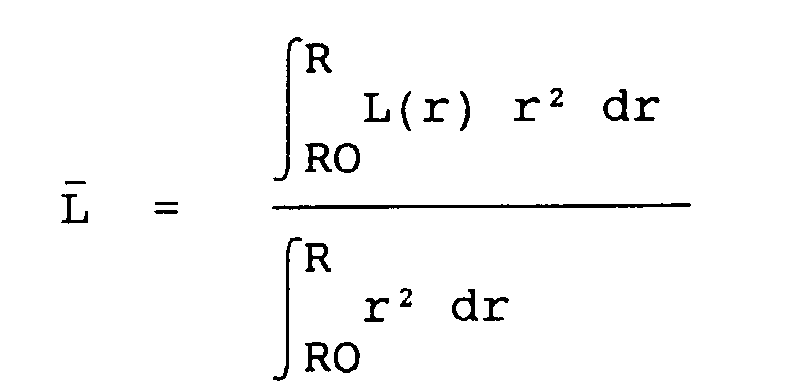
- the total lift of the blade varies in proportion to the average rope L , defined by a square weighting of the radius r : in which RO represents the radius r at the origin of the tail portion of the blade, and R the total radius of the blade.
- patent FR-2 311 713 proposes a construction very different, which consists, among other peculiarities, to broaden the rope, abruptly, beyond a section located approximately 87% of the total radius of the blade R.
- This arrangement contributes to the appearance of vortices intense and stable which pushes the stall limit, in particular when the blade is in the retreating position.
- this concept which concentrates the blade surface towards its end amounts to reducing the effective part of the rotor to a peripheral ring. This makes the induced flow less homogeneous and, therefore, the induced power increases, which is particularly harmful on takeoff.
- the angle arrow ⁇ defined by the line of the aerodynamic foci (about a quarter before the string) and the variation axis step, reduces the effective Mach number and thus in arrow of the free end of the blade constitutes a means effective in reducing the adverse consequences of compressibility of air, in particular the appearance of shock.
- the relative thickness of a blade cross section is defined as the ratio of absolute thickness to length of chord of the profile which constitutes the outline of this section, i.e. e / L.
- twist distribution elementary sections of a blade In addition to the radial distribution of the rope length and the tip tip, twist distribution elementary sections of a blade also intervene in improving the performance of the latter.
- the twisting of a blade consists in varying the setting of the profiles along the span of the blade, so that the outer end of the blade attacks the air under a relatively low incidence, and the blade root under a higher incidence. This allows to distribute the lift of more evenly over the entire surface of the rotor and thus reduce the power absorbed in hovering flight.
- the twist is therefore characterized by the difference in timing between the two ends of the blade.
- a strong twist can cause the outer end of the paddle to wear negatively (down) in position forward when the rotary wing aircraft is moving at great speed. The performance is degraded and, above all, the vibrations increase strongly.
- twist therefore results from a compromise between, on the one hand, hovering and low speeds which require strong twisting and, on the other hand, forward flight for which a more moderate twist is desirable.
- the blade with an arrow end for rotary wing of an aircraft intended to be part of a rotor whose hub is linked to said blade, which is capable of being rotated about the axis of said hub.
- said blade comprising a leading edge and a trailing edge, and being formed of successive elementary cross sections, identified by the distance r separating each of them from the axis of rotation of said hub, and each having a determined chord profile and an aerodynamic focus whose offset relative to the pitch variation axis, orthogonal to each of said sections, determines the deflection of said blade, is remarkable, according to the invention, in that, said blade subdivided, along its longitudinal extent, into four zones, namely a first zone extending from the internal edge of the blade to a first section located at approximately 66% of the total length of the blade, counted by from the axis of rotation of the hub, a second zone extending from the first section to a second section located at approximately 85% of the total length of the blade, a third zone
- the location according to the invention the span position of the maximum chord area, moved close to the middle span area, allows greater speed capacity, along with the larger, resulting extent of the zone of decrease of the cord towards the end.
- This new layout also makes it possible to shorten the area of reduction of rope towards the blade attachment, which causes a structural stiffening which limits the undesirable torsional deformations.
- the offset Y'f is the distance, in the direction of the rope , between the pitch variation axis and the focal point, counted positively when the section is moved in the direction of the leading edge.
- the favorable effect of the arrow angle, reducing the intensity shocks, is fully obtained for values of the arrow angle ⁇ between 30 ° and 45 °, the value maximum of 45 ° being reached only at the end of the blade.
- the invention limits the angle ⁇ to a maximum value of 45 ° at the end thanks to the very gradual decrease of the rope, combined with a straight trailing edge over all the blade portion between the widest string and the end.
- a preferred curve is formed by the points P, Q, R, S and T whose coordinates are as follows: r / R L / L P 0.20223 0.7784 Q 0.66 1.168864 R 0.85 1.168864 S 0.95 0.779222 T 1 0.351538 the lines joining these points to form the PQRST curve being such that: x L / L PQ (r-Rp) / (Rq-Rp) 0.778400 + 0.390464x QR (r-Rq) / (Rr-Rq) 1.168864 RS (r-Rr) / Rs-Rr) 1.1688864 -0.389642x ST (r-Rs) / (Rt-Rs) 0.779222 -0.194821x -0.232863x 2 with Rp, Rq, Rr, Rs and Rt representing the respective positions of P, Q, R, S and T along the blade.
- a preferred curve is formed by the points P ', Q', R ', S' and T 'whose the contact details are as follows: r / R Y'f / R P ' 0.20223 + 0.003396 Q ' 0.66 + 0.011083 R ' 0.85 + 0.011083 S ' 0.95 - 0.035547 You 1 - 0.072113 the lines joining these points to form the curve P'Q'R 'S'T' being such that: x Y'f / R P'Q ' (r-Rp ') / (Rq'-Rp') +0.003396 + 0.007687x Q'R ' (r-Rq ') / (Rr'-Rq') +0.011083 R'S ' (r-Rr ') / (Rs'-Rr') +0.011083 -0.046630x S'
- the parameters of the laws of variation along said longitudinal extent and for each of said zones on the one hand of the length L of the chord of each section relative to the average chord L and, on the other hand, the offset Y'f of the aerodynamic focus of each section relative to the pitch variation axis, substantially ensure the positioning of the overall aerodynamic focus of said blade on said pitch variation axis.
- the law of evolution of the vertical displacement of the focus aerodynamics Zv / R can be, moreover, so that the focal point of the profiles at the outer end of the blade is located significantly lower than the internal part of the blade.
- the marginal vortex generated by the extremity outer of a blade is thus distant from the next blade, this which has the consequence of reducing the intensity of the interaction, especially when hovering.
- the result a marked reduction in the power absorbed by the rotor, especially in hovering and at low speed.
- a preferred curve is formed by the points K, L and M whose coordinates are as follows: r / R e / L K 0.20223 0.15 L 0.4 0.15 M 1 0.07 the lines joining these points to form the KLM limit being such that: x e / L KL (r-Rk) / (Rl-Rk) 0.15 LM (r-Rl) / (Rm-Rk) 0.15 -0.08x with Rk, Rl, and Rm representing the respective positions of K, L and M along the blade.
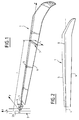
- Figure 2 illustrates, in top view, an example of realization of the blade according to the invention.
- Figure 3 is a curve showing the variation of the length of the rope along the longitudinal extent of the blade.
- Figure 4 is a curve showing the evolution of the offset of the aerodynamic focus along the longitudinal extent of the blade.
- Figure 5 is a curve showing the vertical displacement of the twist center in relation to the construction plane, as defined below, of the blade.
- Figure 6 is a curve showing the evolution of the thickness straight blade sections.
- Blade 1 with arrowed end in accordance with this invention and shown in Figure 1, is part of a rotor whose hub 2 is illustrated in a purely schematic manner and of which the other blades are not shown.
- the blade 1 is linked to the hub 2 by articulation 3 and blade retention, particularly a hinge of pitch change for the blade around an axis 4 called controlled step variation, as is customary.
- the blade 1, comprising a leading edge 5 and a trailing edge 6, is formed of successive elementary cross sections, one of which 7 is shown in FIG. 1.
- Each elementary section 7 is identified by the distance r separating said section of the axis of rotation 2A of the hub 2, and has a determined chord profile L, and an aerodynamic focus (point of application of the variations in the aerodynamic lift forces), the "curve” of which longitudinal extent of the blade is shown at 8 in FIG. 2.
- the offset of the aerodynamic focus with respect to the pitch variation axis 4, orthogonal to said successive sections 7, determines the deflection of the blade, as can be seen better on Figure 2.
- the axis OX is the pitch variation axis 4, so that the first coordinate coincides with the radius r counted from the center of rotation 0.
- the second axis OY, orthogonal to the axis OX constitutes the direction of timing reference, and is directed, arbitrarily, towards the leading edge 5.
- the third axis OZ is orthogonal to the plane defined by the axes OX and OY, and is directed, arbitrarily, upwards (upper surfaces of the profiles).
- the trihedron is in the direct direction if the rotor turns counter-clockwise. It is understood, however, that all that follows remains valid for a rotor rotating clockwise.
- the plan OX, OY will be called construction plan or plan of reference.
- the OX, OY plan will be chosen to coincide with the zero lift plane of the blade.
- the surface of the blade (blade envelope) is generated by a set of elementary plane sections 7 which are all parallel to each other and to the plane OX, OZ and orthogonal to the pitch variation axis OX.
- Each elementary section can be identified by its radius r (distance from the section to the axis OY), comprised between R0 (start of the tail section) and R (outer end of the blade).
- the length of rope L increases generally linearly in said first zone, is maximum and constant in said second zone, decreases linearly in said third zone, and decreases according to a parabolic function in said fourth zone while respecting the continuity of the rate of change of the chord at the common limit with the third zone, and the offset Y'f of the aerodynamic focus with respect to the pitch variation axis, in said first zone, is positive and increases proportional to the distance r , is maximum and constant in said second zone, decreases linearly and becomes negative in said third zone, so that the angle of arrow ⁇ keeps a constant value substantially equal to 25 ° towards the rear, and decreases according to a parabolic function in said fourth zone while respecting the continuity of the arrow angle ⁇ at the common limit with the third zone and until reaching its lowest negative value at the end.
- a preferred curve is formed by the points P, Q, R, S and T whose coordinates are as follows: r / R L / L P 0.20223 0.7784 Q 0.66 1.168864 R 0.85 1.168864 S 0.95 0.779222 T 1 0.351538
- the lines joining these points to form the PQRST curve being such that: x L / L PQ (r-Rp) / (Rq-Rp) 0.778400 + 0.390464x QR (r-Rq) / (Rr-Rq) 1.168864 RS (r-Rr) / Rs-Rr) 1.1688864 -0.389642x ST (r-Rs) / (Rt-Rs) 0.779222 -0.194821x -0.232863x 2 with Rp, Rq, Rr, Rs and Rt representing the respective positions of P, Q, R, S and T along the blade.
- a preferred curve is formed by the points P ', Q', R ', S' and T 'whose coordinates are as follows: r / R Y'f / R P ' 0.20223 + 0.003396 Q ' 0.66 + 0.011083 R ' 0.85 + 0.011083 S ' 0.95 - 0.035547 You 1 - 0.072113 the lines joining these points to form the curve P'Q'R 'S'T' being such that: x Y'f / R P'Q ' (r-Rp ') / (Rq'-Rp') +0.003396 + 0.007687x Q'R ' (r-Rq ') / (Rr'-Rq') +0.011083 R'S ' (r-Rr ') / (Rs'-Rr') +0.011083 -0.0
- the parameters of the laws of variation along said extent longitudinal and for each of said zones on the one hand the length L of the cord of each section relative to the medium chord L and, on the other hand, the offset Y'f of the hearth aerodynamics of each section with respect to the axis of pitch variation, substantially ensure the positioning of the overall aerodynamic focus of said blade on said axis of step variation.
- the form according to the present invention uses profiles including the relative thickness does not exceed 8% at this level end. However, this thickness should not be reduced to less than 6% in order to preserve a capacity for sufficient lift which remains necessary when the end goes backwards.
- a preferred curve is formed by the points K, L and M whose coordinates are as follows: r / R e / L K 0.20223 0.15 L 0.4 0.15 M 1 0.07 the lines joining these points to form the KLM limit being such that: x e / L KL (r-Rk) / (Rl-Rk) 0.15 LM (r-Rl) / (Rm-Rk) 0.15 -0.08x with Rk, Rl, and Rm representing the respective positions of K, L and M along the blade.
Landscapes
- Engineering & Computer Science (AREA)
- Mechanical Engineering (AREA)
- Aviation & Aerospace Engineering (AREA)
- Physics & Mathematics (AREA)
- Fluid Mechanics (AREA)
- Turbine Rotor Nozzle Sealing (AREA)
- Structures Of Non-Positive Displacement Pumps (AREA)
Abstract
Description
- les ondes de choc qui se développent à l'extrados et à l'intrados des pales en position avançante lors du vol à grande vitesse ;
- le décrochage résultant du décollement de la couche limite à l'extrados des pales en position reculante, lors d'une demande de portance en vol de translation ;
- l'interaction du tourbillon engendré par la pale précédente avec la pale suivante, ce qui entraíne une dissipation importante d'énergie en vol stationnaire sous deux formes : puissance induite et puissance de traínée des profils.
- une limite inférieure ABCDE, telle que les coordonnées des
points A, B, C, D et E sont les suivantes :
r/R L/ L A 0 0,55 B 0,66 1,1 C 0,85 1,1 D 0,93 0,73 E 1 0,25 x L/ L AB (r-Ra)/(Rb-Ra) 0,55 + 0,55x BC (r-Rb)/(Rc-Rb) 1,1 CD (r-Rc)/Rd-Rc) 1,1 - 0,37x DE (r-Rd)/(Re-Rd) 0,73 - 0,32375x - 0,15625x2 - une limite supérieure FGHIJ, telle que les coordonnées des
points F, G, H, I et J sont les suivantes :
r/R L/ L F 0 0,65 G 0,66 1,2 H 0,85 1,2 I 0,97 0,83 J 1 0,45 x L/ L FG (r-Rf)/(Rg-Rf) 0,65 + 0,55x GH (r-Rg)/(Rh-Rg) 1,2 HI (r-Rh)/Ri-Rh) 1,2 - 0,37x IJ (r-Ri)/(Rj-Ri) 0,83 - 0,0925x - 0,2875x2
| r/R | L/ | |
| P | 0,20223 | 0,7784 |
| Q | 0,66 | 1,168864 |
| R | 0,85 | 1,168864 |
| S | 0,95 | 0,779222 |
| T | 1 | 0,351538 |
| x | L/ | |
| PQ | (r-Rp)/(Rq-Rp) | 0,778400 +0,390464x |
| QR | (r-Rq)/(Rr-Rq) | 1,168864 |
| RS | (r-Rr)/Rs-Rr) | 1,168864 -0,389642x |
| ST | (r-Rs)/(Rt-Rs) | 0,779222 -0,194821x -0,232863x2 |
- une limite inférieure A'B'C'D'E', telle que les coordonnées
des points A', B', C', D' et E' sont les suivantes :
r/R Y'f/R A' 0 0 B' 0,66 + 0,005 C' 0,85 + 0,005 D' 0,93 - 0,053 E' 1 - 0,105 x Y'f/R A'B' (r-Ra')/(Rb'-Ra') +0,005x B'C' (r-Rb')/(Rc'-Rb') +0,005 C'D' (r-Rc')/(Rd'-Rc') +0,005 -0,058x D'E' (r-Rd')/(Re'-Rd') -0,053 -0,05075x - 0,00125x2 - une limite supérieure F'G'H'I'J', telle que les coordonnées
des points F', G', H', I' et J' sont les suivantes :
r/R Y'f/R F' 0 0 G' 0,66 + 0,030 H' 0,85 + 0,030 I' 0,97 - 0,013 J' 1 - 0,050 x Y'f/R F'G' (r-Rf')/(Rg'-Rf') +0,03x G'H' (r-Rg')/(Rh'-Rg') +0,03 H'I' (r-Rh')/(Ri'-Rh') +0,03 -0,043x I'J' (r-Ri')/(Rj'-Ri') -0,013 -0,01075x - 0,02625x2
| r/R | Y'f/R | |
| P' | 0,20223 | + 0,003396 |
| Q' | 0,66 | + 0,011083 |
| R' | 0,85 | + 0,011083 |
| S' | 0,95 | - 0,035547 |
| T' | 1 | - 0,072113 |
| x | Y'f/R | |
| P'Q' | (r-Rp')/(Rq'-Rp') | +0,003396 +0,007687x |
| Q'R' | (r-Rq')/(Rr'-Rq') | +0,011083 |
| R'S' | (r-Rr')/(Rs'-Rr') | +0,011083 -0,046630x |
| S'T' | (r-Rs')/(Rt'-Rs') | -0,035547 -0,023315x -0,013251x2 |
- une limite inférieure A"B"C"D"E", telle que les coordonnées
des points A", B", C", D" et E" sont les suivantes :
r/R Zv/R A" 0 - 0,001 B" 0,66 - 0,001 C" 0,85 - 0,001 D" 0,93 - 0,001 E" 1 - 0,015 x Zv/R A"B" (r-Ra")/(Rb"-Ra") -0,001 B"C" (r-Rb")/(Rc"-Rb") -0,001 C"D" (r-Rc")/(Rd"-Rc") -0,001 D"E" (r-Rd")/(Re"-Rd") -0,001 -0,014x2 - une limite supérieure F"G"H"I"J", telle que les coordonnées
des points F", G", H", I" et J" sont les suivantes :
r/R Zv/R F" 0 + 0,001 G" 0,66 + 0,001 H" 0,85 + 0,001 I" 0,97 + 0,001 J" 1 - 0,005 x Zv/R F"G" (r-Rf")/(Rg"-Rf") +0,001 G"H" (r-Rg")/(Rh"-Rg") +0,001 H"I" (r-Rh")/(Ri"-Rh") +0,001 I"J" (r-Ri")/(Rj"-Ri") +0,001 -0,006x2
| r/R | Zv/R | |
| P" | 0,20223 | 0 |
| Q" | 0,66 | 0 |
| R" | 0,85 | 0 |
| S" | 0,95 | 0 |
| T" | 1 | -0,009050 |
| x | Zv/R | |
| P"Q" | (r-Rp")/(Rq"-Rp") | 0 |
| Q"R" | (r-Rq")/(Rr"-Rq") | 0 |
| R"S" | (r-Rr")/(Rs"-Rr") | 0 |
| S"T" | (r-Rs")/(Rt"-Rs") | - 0,00905x2 |
- une limite inférieure UVW, telle que les coordonnées des
points U, V et W sont les suivantes :
r/R e/L U 0 0,14 V 0,4 0,14 W 1 0,06 x e/L UV (r-Ru)/(Rv-Ru) 0,14 VW (r-Rv)/(Rw-Rv) 0,14 -0,08x - une limite supérieure XYZ, telle que les coordonnées des
points X, Y et Z sont les suivantes :
r/R e/L X 0 0,16 Y 0,4 0,16 Z 1 0,08 x e/L XY (r-Rx)/(Ry-Rx) 0,16 YZ (r-Ry)/(Rz-Ry) 0,16 -0,08x
| r/R | e/L | |
| K | 0,20223 | 0,15 |
| L | 0,4 | 0,15 |
| M | 1 | 0,07 |
| x | e/L | |
| KL | (r-Rk)/(Rl-Rk) | 0,15 |
| LM | (r-Rl)/(Rm-Rk) | 0,15 -0,08x |
- une première zone, qui s'étend depuis la section R0, correspondant au début de la partie empennée, jusqu'à la section R1 située sensiblement à 66% du rayon total R ;
- une deuxième zone, qui s'étend depuis la section R1 jusqu'à la section R2 située sensiblement à 85% du rayon total R ;
- une troisième zone, qui s'étend depuis la section R2 jusqu'à la section R3 située entre 93% et 97% du rayon total R ; et
- une quatrième zone, qui s'étend depuis la section R3 jusqu'au bout libre de la pale (rayon R).
- une limite inférieure ABCDE, telle que les coordonnées des
points A, B, C, D et E sont les suivantes :
r/R L/ L A 0 0,55 B 0,66 1,1 C 0,85 1,1 D 0,93 0,73 E 1 0,25 x L/ L AB (r-Ra)/(Rb-Ra) 0,55 + 0,55x BC (r-Rb)/(Rc-Rb) 1,1 CD (r-Rc)/Rd-Rc) 1,1 - 0,37x DE (r-Rd)/(Re-Rd) 0,73 - 0,32375x - 0,15625x2 - une limite supérieure FGHIJ, telle que les coordonnées des
points F, G, H, I et J sont les suivantes :
r/R L/ L F 0 0,65 G 0,66 1,2 H 0,85 1,2 I 0,97 0,83 J 1 0,45 x L/ L FG (r-Rf)/(Rg-Rf) 0,65 + 0,55x GH (r-Rg)/(Rh-Rg) 1,2 HI (r-Rh)/Ri-Rh) 1,2 - 0,37x IJ (r-Ri)/(Rj-Ri) 0,83 - 0,0925x - 0,2875x2
| r/R | L/ | |
| P | 0,20223 | 0,7784 |
| Q | 0,66 | 1,168864 |
| R | 0,85 | 1,168864 |
| S | 0,95 | 0,779222 |
| T | 1 | 0,351538 |
| x | L/ | |
| PQ | (r-Rp)/(Rq-Rp) | 0,778400 +0,390464x |
| QR | (r-Rq)/(Rr-Rq) | 1,168864 |
| RS | (r-Rr)/Rs-Rr) | 1,168864 -0,389642x |
| ST | (r-Rs)/(Rt-Rs) | 0,779222 -0,194821x -0,232863x2 |
- une limite inférieure A'B'C'D'E', telle que les coordonnées
des points A', B', C', D' et E' sont les suivantes :
r/R Y'f/R A' 0 0 B' 0,66 + 0,005 C' 0,85 + 0,005 D' 0,93 - 0,053 E' 1 - 0,105 x Y'f/R A'B' (r-Ra')/(Rb'-Ra') +0,005x B'C' (r-Rb')/(Rc'-Rb') +0,005 C'D' (r-Rc')/(Rd'-Rc') +0,005 -0,058x D'E' (r-Rd')/(Re'-Rd') -0,053 -0,05075x - 0,00125x2 - une limite supérieure F'G'H'I'J', telle que les coordonnées
des points F', G', H', I' et J' sont les suivantes :
r/R Y'f/R F' 0 0 G' 0,66 + 0,030 H' 0,85 + 0,030 I' 0,97 - 0,013 J' 1 - 0,050 x Y'f/R F'G' (r-Rf')/(Rg'-Rf') +0,03x G'H' (r-Rg')/(Rh'-Rg') +0,03 H'I' (r-Rh')/(Ri'-Rh') +0,03 -0,043x I'J' (r-Ri')/(Rj'-Ri') -0,013 -0,01075x - 0,02625x2
| r/R | Y'f/R | |
| P' | 0,20223 | + 0,003396 |
| Q' | 0,66 | + 0,011083 |
| R' | 0,85 | + 0,011083 |
| S' | 0,95 | - 0,035547 |
| T' | 1 | - 0,072113 |
| x | Y'f/R | |
| P'Q' | (r-Rp')/(Rq'-Rp') | +0,003396 +0,007687x |
| Q'R' | (r-Rq')/(Rr'-Rq') | +0,011083 |
| R'S' | (r-Rr')/(Rs'-Rr') | +0,011083 -0,046630x |
| S'T' | (r-Rs')/(Rt'-Rs') | -0,035547 -0,023315x -0,013251x2 |
- une limite inférieure A"B"C"D"E", telle que les coordonnées
des points A", B", C", D" et E" sont les suivantes :
r/R Zv/R A" 0 - 0,001 B" 0,66 - 0,001 C" 0,85 - 0,001 D" 0,93 - 0,001 E" 1 - 0,015 x Zv/R A"B" (r-Ra")/(Rb"-Ra") -0,001 B"C" (r-Rb")/(Rc"-Rb") -0,001 C"D" (r-Rc")/(Rd"-Rc") -0,001 D"E" (r-Rd")/(Re"-Rd") -0,001 -0,014x2 - une limite supérieure F"G"H"I"J", telle que les coordonnées
des points F", G", H", I" et J" sont les suivantes :
r/R Zv/R F" 0 + 0,001 G" 0,66 + 0,001 H" 0,85 + 0,001 I" 0,97 + 0,001 J" 1 - 0,005 x Zv/R F"G" (r-Rf")/(Rg"-Rf") +0,001 G"H" (r-Rg")/(Rh"-Rg") +0,001 H"I" (r-Rh")/(Ri"-Rh") +0,001 I"J" (r-Ri")/(Rj"-Ri") +0,001 -0,006x2
| r/R | Zv/R | |
| P" | 0,20223 | 0 |
| Q" | 0,66 | 0 |
| R" | 0,85 | 0 |
| S" | 0,95 | 0 |
| T" | 1 | -0,009050 |
| x | Zv/R | |
| P"Q" | (r-RP")/(Rq"-RP") | 0 |
| Q"R" | (r-Rq")/(Rr"-Rq") | 0 |
| R"S" | (r-Rr")/(Rs"-Rr") | 0 |
| S"T" | (r-Rs")/(Rt"-Rs") | - 0,00905x2 |
- une limite inférieure UVW, telle que les coordonnées des
points U, V et W sont les suivantes :
r/R e/L U 0 0,14 V 0,4 0,14 W 1 0,06 x e/L UV (r-Ru)/(Rv-Ru) 0,14 VW (r-Rv)/(Rw-Rv) 0,14 -0,08x - une limite supérieure XYZ, telle que les coordonnées des
points X, Y et Z sont les suivantes :
r/R e/L X 0 0,16 Y 0,4 0,16 Z 1 0,08 x e/L XY (r-Rx)/(Ry-Rx) 0,16 YZ (r-Ry)/(Rz-Ry) 0,16 -0,08x
| r/R | e/L | |
| K | 0,20223 | 0,15 |
| L | 0,4 | 0,15 |
| M | 1 | 0,07 |
| x | e/L | |
| KL | (r-Rk)/(Rl-Rk) | 0,15 |
| LM | (r-Rl)/(Rm-Rk) | 0,15 -0,08x |
Claims (10)
- Pale à extrémité en flèche pour voilure tournante d'aéronef, destinée à faire partie d'un rotor dont le moyeu (2) est lié à ladite pale (1), laquelle est susceptible d'être entraínée en rotation autour de l'axe dudit moyeu, ladite pale (1) comportant un bord d'attaque (5) et un bord de fuite (6), et étant formée de sections transversales élémentaires successives (7), identifiées par la distance r séparant chacune d'entre elles de l'axe de rotation dudit moyeu, et présentant, chacune, un profil de corde déterminée et un foyer aérodynamique dont le déport par rapport à l'axe de variation de pas, orthogonal à chacune desdites sections, détermine la flèche de ladite pale,
caractérisée en ce que, ladite pale (1) étant subdivisée, le long de son étendue longitudinale, en quatre zones, à savoir une première zone s'étendant du bord interne de la pale R0 à une première section R1 située à sensiblement 66% de la longueur totale de la pale, comptée à partir de l'axe de rotation du moyeu, une deuxième zone s'étendant de la première section R1 à une deuxième section R2 située à sensiblement 85% de la longueur totale de la pale, une troisième zone s'étendant de la deuxième section R2 à une troisième section R3 située entre 93% et 97% de la longueur totale de la pale, et une quatrième zone s'étendant de la troisième section R3 au bord externe libre R de la pale, la longueur de corde L croít de façon généralement linéaire dans ladite première zone, est maximale et constante dans ladite deuxième zone, décroít linéairement dans ladite troisième zone, et décroít suivant une fonction parabolique dans ladite quatrième zone en respectant la continuité du taux de variation de la corde à la limite commune avec la troisième zone, et le déport Y'f du foyer aérodynamique par rapport à l'axe de variation de pas, dans ladite première zone, est positif et augmente proportionnellement à la distance r, est maximal et constant dans ladite deuxième zone, décroít de façon linéaire et devient négatif dans ladite troisième zone, de sorte que l'angle de flèche Λ garde une valeur constante sensiblement égale à 25° vers l'arrière, et décroít suivant une fonction parabolique dans ladite quatrième zone en respectant la continuité de l'angle de flèche Λ à la limite commune avec la troisième zone. - Pale selon la revendication 1,
caractérisée en ce que la loi d'évolution de la longueur de corde est comprise entre :une limite inférieure ABCDE, telle que les coordonnées des points A, B, C, D et E sont les suivantes :r/R L/ L A 0 0,55 B 0,66 1,1 C 0,85 1,1 D 0,93 0,73 E 1 0,25 x L/ L AB (r-Ra)/(Rb-Ra) 0,55 + 0,55x BC (r-Rb)/(Rc-Rb) 1,1 CD (r-Rc)/Rd-Rc) 1,1 - 0,37x DE (r-Rd)/(Re-Rd) 0,73 - 0,32375x - 0,15625x2 une limite supérieure FGHIJ, telle que les coordonnées des points F, G, H, I et J sont les suivantes :r/R L/ L F 0 0,65 G 0,66 1,2 H 0,85 1,2 I 0,97 0,83 J 1 0,45 x L/ L FG (r-Rf)/(Rg-Rf) 0,65 + 0,55x GH (r-Rg)/(Rh-Rg) 1,2 HI (r-Rh)/Ri-Rh) 1,2 - 0,37x IJ (r-Ri)/(Rj-Ri) 0,83 - 0,0925x - 0,2875x2 - Pale selon la revendication 2,
caractérisée en ce que, entre les limites inférieure ABCDE et supérieure FGHIJ, une courbe préférée est formée par les points P, Q, R, S et T dont les coordonnées sont les suivantes :r/R L/ L P 0,20223 0,7784 Q 0,66 1,168864 R 0,85 1,168864 S 0,95 0,779222 T 1 0,351538 x L/ L PQ (r-Rp)/(Rq-Rp) 0,778400 +0,390464x QR (r-Rq)/(Rr-Rq) 1,168864 RS (r-Rr)/Rs-Rr) 1,168864 -0,389642x ST (r-Rs)/(Rt-Rs) 0,779222 -0,194821x -0,232863x2 - Pale selon l'une quelconque des revendications 1 à 3, caractérisée en ce que la loi d'évolution du déport du foyer aérodynamique est comprise entre :une limite inférieure A'B'C'D'E', telle que les coordonnées des points A', B', C', D' et E' sont les suivantes :
r/R Y'f/R A' 0 0 B' 0,66 + 0,005 C' 0,85 + 0,005 D' 0,93 - 0,053 E' 1 - 0,105 x Y'f/R A'B' (r-Ra')/(Rb'-Ra') +0,005x B'C' (r-Rb')/(Rc'-Rb') +0,005 C'D' (r-Rc')/(Rd'-Rc') +0,005 -0,058x D'E' (r-Rd')/(Re'-Rd') -0,053 -0,05075x - 0,00125x2 une limite supérieure F'G'H'I'J', telle que les coordonnées des points F', G', H', I' et J' sont les suivantes :r/R Y'f/R F' 0 0 G' 0,66 + 0,030 H' 0,85 + 0,030 I' 0,97 - 0,013 J' 1 - 0,050 x Y'f/R F'G' (r-Rf')/(Rg'-Rf') +0,03x G'H' (r-Rg')/(Rh'-Rg') +0,03 H'I' (r-Rh')/(Ri'-Rh') +0,03 -0,043x I'J' (r-Ri')/(Rj'-Ri') -0,013 -0,01075x - 0,02625x2 - Pale selon la revendication 4,
caractérisée en ce que, entre les limites inférieure A'B'C' D'E' et supérieure F'G'H'I'J', une courbe préférée est formée par les points P', Q', R', S' et T' dont les coordonnées sont les suivantes :r/R Y'f/R P' 0,20223 + 0,003396 Q' 0,66 + 0,011083 R' 0,85 + 0,011083 S' 0,95 - 0,035547 T' 1 - 0,072113 x Y'f/R P'Q' (r-Rp')/(Rq'-Rp') +0,003396 +0,007687x Q'R' (r-Rq')/(Rr'-Rq') +0,011083 R'S' (r-Rr')/(Rs'-Rr') +0,011083 -0,046630x S'T' (r-Rs')/(Rt'-Rs') -0,035547 -0,023315x -0,013251x2 - Pale selon l'une quelconque des revendications 1 à 5, caractérisée en ce que les paramètres des lois de variation le long de ladite étendue longitudinale et pour chacune desdites zones, d'une part de la longueur L de la corde de chaque section par rapport à la corde moyenne
L et, d'autre part, du déport Y'f du foyer aérodynamique de chaque section par rapport à l'axe de variation de pas, assurent sensiblement le positionnement du foyer aérodynamique global de ladite pale sur ledit axe de variation de pas. - Pale selon l'une quelconque des revendications 1 à 6, caractérisée en ce que la loi d'évolution du déplacement vertical du foyer aérodynamique Zv/R est comprise entre :une limite inférieure A"B"C"D"E", telle que les coordonnées des points A", B", C", D" et E" sont les suivantes :
r/R Zv/R A" 0 - 0,001 B" 0,66 - 0,001 C" 0,85 - 0,001 D" 0,93 - 0,001 E" 1 - 0,015 x Zv/R A"B" (r-Ra")/(Rb"-Ra") -0,001 B"C" (r-Rb")/(Rc"-Rb") -0,001 C"D" (r-Rc")/(Rd"-Rc") -0,001 D"E" (r-Rd")/(Re"-Rd") -0,001 -0,014x2 une limite supérieure F"G"H"I"J", telle que les coordonnées des points F", G", H", I" et J" sont les suivantes :r/R Zv/R F" 0 + 0,001 G" 0,66 + 0,001 H" 0,85 + 0,001 I" 0,97 + 0,001 J" 1 - 0,005 x Zv/R F"G" (r-Rf")/(Rg"-Rf") +0,001 G"H" (r-Rg")/(Rh"-Rg") +0,001 H"I" (r-Rh")/(Ri"-Rh") +0,001 I"J" (r-Ri")/(Rj"-Ri") +0,001 -0,006x2 - Pale selon la revendication 7,
caractérisée en ce que, entre les limites inférieure A"B"C" D"E" et supérieure F"G"H"I"J", une courbe préférée est formée par les points P", Q", R", S" et T" dont les coordonnées sont les suivantes :r/R Zv/R P" 0,20223 0 Q" 0,66 0 R" 0,85 0 S" 0,95 0 T" 1 -0,009050 x Zv/R P"Q" (r-Rp")/(Rq"-Rp") 0 Q"R" (r-Rq")/(Rr"-Rq") 0 R"S" (r-Rr")/(Rs"-Rr") 0 S"T" (r-Rs")/(Rt"-Rs") - 0,00905x2 - Pale selon l'une quelconque des revendications 1 à 8, caractérisée en ce que la loi d'évolution de l'épaisseur relative des sections e/L est comprise entre :une limite inférieure UVW, telle que les coordonnées des points U, V et W sont les suivantes :
r/R e/L U 0 0,14 V 0,4 0,14 W 1 0,06 x e/L UV (r-Ru)/(Rv-Ru) 0,14 VW (r-Rv)/(Rw-Rv) 0,14 -0,08x une limite supérieure XYZ, telle que les coordonnées des points X, Y et Z sont les suivantes :r/R e/L X 0 0,16 Y 0,4 0,16 Z 1 0,08 x e/L XY (r-Rx)/(Ry-Rx) 0,16 YZ (r-Ry)/(Rz-Ry) 0,16 -0,08x - Pale selon la revendication 9,
caractérisée en ce que, entre les limites inférieure UVW et supérieure XYZ, une courbe préférée est formée par les points K, L et M dont les coordonnées sont les suivantes :r/R e/L K 0,20223 0,15 L 0,4 0,15 M 1 0,07 x e/L KL (r-Rk)/(Rl-Rk) 0,15 LM (r-Rl)/(Rm-Rk) 0,15 -0,08x
Applications Claiming Priority (2)
| Application Number | Priority Date | Filing Date | Title |
|---|---|---|---|
| FR9614066 | 1996-11-19 | ||
| FR9614066A FR2755941B1 (fr) | 1996-11-19 | 1996-11-19 | Pale a extremite en fleche pour voilure tournante d'aeronef |
Publications (2)
| Publication Number | Publication Date |
|---|---|
| EP0842846A1 true EP0842846A1 (fr) | 1998-05-20 |
| EP0842846B1 EP0842846B1 (fr) | 2002-08-28 |
Family
ID=9497748
Family Applications (1)
| Application Number | Title | Priority Date | Filing Date |
|---|---|---|---|
| EP97402633A Expired - Lifetime EP0842846B1 (fr) | 1996-11-19 | 1997-11-05 | Pale à extrémité en flèche pour voilure tournante d'aéronef |
Country Status (8)
| Country | Link |
|---|---|
| US (1) | US6000911A (fr) |
| EP (1) | EP0842846B1 (fr) |
| JP (1) | JP3802209B2 (fr) |
| CN (1) | CN1077859C (fr) |
| DE (1) | DE69714947T2 (fr) |
| FR (1) | FR2755941B1 (fr) |
| RU (1) | RU2139811C1 (fr) |
| ZA (1) | ZA979933B (fr) |
Cited By (3)
| Publication number | Priority date | Publication date | Assignee | Title |
|---|---|---|---|---|
| FR3045565A1 (fr) * | 2015-12-21 | 2017-06-23 | Airbus Helicopters | Pale de rotor d'aeronef a geometrie adaptee pour l'ameloration acoustique lors d'un vol d'approche et l'amelioration des performances en vol d'avancement |
| US10220943B2 (en) | 2015-12-21 | 2019-03-05 | Airbus Helicopters | Aircraft rotor blade of shape adapted for acoustic improvement during approach flights and for improving performance in hovering flight and in forward flight |
| EP4650272A1 (fr) | 2024-05-17 | 2025-11-19 | Airbus Helicopters | Pale de voilure tournante d'un aéronef, et aéronef muni d'une telle pale |
Families Citing this family (44)
| Publication number | Priority date | Publication date | Assignee | Title |
|---|---|---|---|---|
| JP3189251B2 (ja) * | 1999-03-12 | 2001-07-16 | 株式会社コミュータヘリコプタ先進技術研究所 | 回転翼機のロータブレード |
| FR2793766B1 (fr) | 1999-05-21 | 2001-07-13 | Eurocopter France | Pale pour voilure tournante d'aeronef |
| US6497385B1 (en) | 2000-11-08 | 2002-12-24 | Continuum Dynamics, Inc. | Rotor blade with optimized twist distribution |
| RU2228882C2 (ru) * | 2001-08-03 | 2004-05-20 | Востропятов Иван Давыдович | Лопасть воздушного винта |
| GB0420601D0 (en) * | 2004-09-16 | 2004-10-20 | Qinetiq Ltd | Wing tip devices |
| US7344360B2 (en) * | 2004-09-29 | 2008-03-18 | General Electric Company | Wind turbine rotor blade with in-plane sweep and devices using same, and methods for making same |
| US7946526B2 (en) * | 2004-11-05 | 2011-05-24 | Nachman Zimet | Rotary-wing vehicle system |
| US7600976B2 (en) * | 2005-05-31 | 2009-10-13 | Sikorsky Aircraft Corporation | Rotor blade twist distribution for a high speed rotary-wing aircraft |
| US7252479B2 (en) * | 2005-05-31 | 2007-08-07 | Sikorsky Aircraft Corporation | Rotor blade for a high speed rotary-wing aircraft |
| US7883392B2 (en) | 2008-08-04 | 2011-02-08 | Silverlit Toys Manufactory Ltd. | Toy helicopter |
| USD545755S1 (en) | 2006-01-19 | 2007-07-03 | Silverlit Toys Manufactory, Ltd. | Helicopter |
| US7815482B2 (en) | 2006-01-19 | 2010-10-19 | Silverlit Toys Manufactory, Ltd. | Helicopter |
| US8002604B2 (en) | 2006-01-19 | 2011-08-23 | Silverlit Limited | Remote controlled toy helicopter |
| US7662013B2 (en) | 2006-01-19 | 2010-02-16 | Silverlit Toys Manufactory Ltd. | Helicopter with horizontal control |
| US8357023B2 (en) | 2006-01-19 | 2013-01-22 | Silverlit Limited | Helicopter |
| BE1016960A3 (nl) | 2006-01-19 | 2007-11-06 | Rostyne Alexander Jozef Magdal | Verbeterde helikopter. |
| USD579403S1 (en) | 2006-01-19 | 2008-10-28 | Silverlit Toys Manufactory, Ltd. | Helicopter propeller rotor |
| US7854593B2 (en) * | 2006-02-16 | 2010-12-21 | Sikorsky Aircraft Corporation | Airfoil for a helicopter rotor blade |
| USD582336S1 (en) | 2006-08-03 | 2008-12-09 | Silverlit Toys Manufactory Ltd. | Helicopter blade, shafts and fins |
| USD580344S1 (en) | 2006-08-03 | 2008-11-11 | Silverlit Toys Manufactory, Ltd. | Helicopter rotors, blades and shafts |
| US8016566B2 (en) * | 2006-08-03 | 2011-09-13 | Bell Helicopter Textron Inc. | High performance low noise rotorcraft blade aerodynamic design |
| RU2333867C2 (ru) * | 2006-10-05 | 2008-09-20 | Иван Давыдович Востропятов | Вертолет |
| USD583297S1 (en) | 2007-10-31 | 2008-12-23 | Silverlit Toys Manufactory Ltd. | Helicopter rotors |
| USD582833S1 (en) | 2007-10-31 | 2008-12-16 | Silverlit Toys Manufactory Ltd. | Rotors for helicopter |
| USD576215S1 (en) | 2007-10-31 | 2008-09-02 | Silverlit Toys Manufactory, Ltd. | Helicopter body |
| USD568947S1 (en) | 2007-10-31 | 2008-05-13 | Silverlit Toys Manufactory, Ltd. | Helicopter |
| US7762785B2 (en) * | 2007-12-10 | 2010-07-27 | Sikorsky Aircraft Corporation | Main rotor blade with integral tip section |
| EP2123556B1 (fr) * | 2008-05-22 | 2010-12-08 | Agusta S.p.A. | Pale de rotor anticouple |
| US7854595B2 (en) * | 2008-07-30 | 2010-12-21 | General Electric Company | Wind turbine blade tip shapes |
| US8052500B2 (en) | 2008-11-25 | 2011-11-08 | Silverlit Limited | Helicopter with main and auxiliary rotors |
| EP2505500B1 (fr) | 2011-03-31 | 2016-09-14 | AIRBUS HELICOPTERS DEUTSCHLAND GmbH | Pale de rotor à bruit et performance améliorés pour hélicoptère |
| FR3005301B1 (fr) * | 2013-05-03 | 2015-05-29 | Eurocopter France | Rotor carene d'aeronef, et giravion |
| CN105947160B (zh) * | 2016-05-05 | 2018-07-24 | 哈尔滨工程大学 | 一种降低叶根处应力并减小梢涡的螺旋桨 |
| US10858088B2 (en) * | 2016-08-31 | 2020-12-08 | David E. Shormann | Biomimetic airfoil bodies and methods of designing and making same |
| EP3293112B1 (fr) | 2016-09-07 | 2018-12-05 | Leonardo S.p.A. | Rotor pour un avion capable de vol stationnaire et son procédé de commande |
| CN108688794A (zh) * | 2018-04-18 | 2018-10-23 | 中山市朗宇模型有限公司 | 螺旋桨 |
| WO2019227268A1 (fr) * | 2018-05-28 | 2019-12-05 | 深圳市大疆创新科技有限公司 | Ensemble hélice, ensemble d'alimentation et aéronef |
| US12269586B2 (en) * | 2018-06-15 | 2025-04-08 | The Texas A&M University System | Hover-capable aircraft |
| US11999466B2 (en) * | 2019-11-14 | 2024-06-04 | Skydio, Inc. | Ultra-wide-chord propeller |
| CN112173075B (zh) * | 2020-09-25 | 2022-12-30 | 中国直升机设计研究所 | 一种直升机低噪声旋翼桨叶气动外形 |
| CN112977816B (zh) * | 2021-05-17 | 2021-08-06 | 北京三快在线科技有限公司 | 旋翼飞行器的桨叶及旋翼飞行器 |
| CN114560082B (zh) * | 2022-02-16 | 2023-07-04 | 西南科技大学 | 一种能有效控制桨尖涡的组合修形的桨尖结构及设计方法 |
| US12116119B2 (en) * | 2022-03-28 | 2024-10-15 | Lockheed Martin Corporation | High speed rotor blade design |
| JP7793500B2 (ja) * | 2022-09-30 | 2026-01-05 | 本田技研工業株式会社 | ブレード及びロータ |
Citations (7)
| Publication number | Priority date | Publication date | Assignee | Title |
|---|---|---|---|---|
| US3066742A (en) * | 1957-01-11 | 1962-12-04 | Georgia Tech Res Inst | Rotor blade |
| FR2311713A1 (fr) | 1975-05-19 | 1976-12-17 | Westland Aircraft Ltd | Pales pour rotor d'helicoptere |
| FR2397328A1 (fr) | 1977-07-13 | 1979-02-09 | United Technologies Corp | Pales et rotors d'helicopteres ameliores |
| FR2473983A1 (fr) | 1980-01-21 | 1981-07-24 | United Technologies Corp | Pale d'helicoptere perfectionnee dont la tete presente une combinaison selectionnee de deport dans le plan de rotation, de conicite et d'angle de diedre lateral negatif dans le but d'ameliorer le rendement en vol |
| FR2617118A1 (fr) | 1987-06-29 | 1988-12-30 | Aerospatiale | Pale a extremite courbe pour voilure tournante d'aeronef |
| FR2636593A1 (fr) | 1988-09-19 | 1990-03-23 | Aerospatiale | Pale pour voilure tournante d'aeronef et voilure tournante comportant une telle pale |
| FR2689852A1 (fr) | 1992-04-09 | 1993-10-15 | Eurocopter France | Pale pour voilure tournante d'aéronef, à extrémité en flèche. |
-
1996
- 1996-11-19 FR FR9614066A patent/FR2755941B1/fr not_active Expired - Lifetime
-
1997
- 1997-11-05 EP EP97402633A patent/EP0842846B1/fr not_active Expired - Lifetime
- 1997-11-05 ZA ZA9709933A patent/ZA979933B/xx unknown
- 1997-11-05 DE DE69714947T patent/DE69714947T2/de not_active Expired - Lifetime
- 1997-11-18 US US08/972,274 patent/US6000911A/en not_active Expired - Lifetime
- 1997-11-18 RU RU97120828A patent/RU2139811C1/ru active
- 1997-11-19 CN CN97126455A patent/CN1077859C/zh not_active Expired - Lifetime
- 1997-11-19 JP JP31851197A patent/JP3802209B2/ja not_active Expired - Lifetime
Patent Citations (7)
| Publication number | Priority date | Publication date | Assignee | Title |
|---|---|---|---|---|
| US3066742A (en) * | 1957-01-11 | 1962-12-04 | Georgia Tech Res Inst | Rotor blade |
| FR2311713A1 (fr) | 1975-05-19 | 1976-12-17 | Westland Aircraft Ltd | Pales pour rotor d'helicoptere |
| FR2397328A1 (fr) | 1977-07-13 | 1979-02-09 | United Technologies Corp | Pales et rotors d'helicopteres ameliores |
| FR2473983A1 (fr) | 1980-01-21 | 1981-07-24 | United Technologies Corp | Pale d'helicoptere perfectionnee dont la tete presente une combinaison selectionnee de deport dans le plan de rotation, de conicite et d'angle de diedre lateral negatif dans le but d'ameliorer le rendement en vol |
| FR2617118A1 (fr) | 1987-06-29 | 1988-12-30 | Aerospatiale | Pale a extremite courbe pour voilure tournante d'aeronef |
| FR2636593A1 (fr) | 1988-09-19 | 1990-03-23 | Aerospatiale | Pale pour voilure tournante d'aeronef et voilure tournante comportant une telle pale |
| FR2689852A1 (fr) | 1992-04-09 | 1993-10-15 | Eurocopter France | Pale pour voilure tournante d'aéronef, à extrémité en flèche. |
Cited By (7)
| Publication number | Priority date | Publication date | Assignee | Title |
|---|---|---|---|---|
| FR3045565A1 (fr) * | 2015-12-21 | 2017-06-23 | Airbus Helicopters | Pale de rotor d'aeronef a geometrie adaptee pour l'ameloration acoustique lors d'un vol d'approche et l'amelioration des performances en vol d'avancement |
| EP3184426A1 (fr) | 2015-12-21 | 2017-06-28 | Airbus Helicopters | Pale de rotor d aeronef a geometrie adaptee pour l amelioration de l acoustique lors d'un vol d approche et l amelioration des performances en vol d avancement |
| JP2017141014A (ja) * | 2015-12-21 | 2017-08-17 | エアバス ヘリコプターズ | 接近飛行の間の音響改善用に、および前進飛行中の性能を改善するように適合された形状の航空機ロータブレード |
| US10220943B2 (en) | 2015-12-21 | 2019-03-05 | Airbus Helicopters | Aircraft rotor blade of shape adapted for acoustic improvement during approach flights and for improving performance in hovering flight and in forward flight |
| US10414490B2 (en) | 2015-12-21 | 2019-09-17 | Airbus Helicopters | Aircraft rotor blade of shape adapted for acoustic improvement during an approach flight and for improving performance in forward flight |
| EP4650272A1 (fr) | 2024-05-17 | 2025-11-19 | Airbus Helicopters | Pale de voilure tournante d'un aéronef, et aéronef muni d'une telle pale |
| FR3162204A1 (fr) * | 2024-05-17 | 2025-11-21 | Airbus Helicopters | Pale de voilure tournante d’un aéronef, et aéronef muni d’une telle pale |
Also Published As
| Publication number | Publication date |
|---|---|
| JPH1199994A (ja) | 1999-04-13 |
| US6000911A (en) | 1999-12-14 |
| ZA979933B (en) | 1998-05-25 |
| DE69714947T2 (de) | 2003-04-24 |
| EP0842846B1 (fr) | 2002-08-28 |
| CN1185399A (zh) | 1998-06-24 |
| CN1077859C (zh) | 2002-01-16 |
| JP3802209B2 (ja) | 2006-07-26 |
| FR2755941A1 (fr) | 1998-05-22 |
| FR2755941B1 (fr) | 1999-01-15 |
| RU2139811C1 (ru) | 1999-10-20 |
| DE69714947D1 (de) | 2002-10-02 |
Similar Documents
| Publication | Publication Date | Title |
|---|---|---|
| EP0842846B1 (fr) | Pale à extrémité en flèche pour voilure tournante d'aéronef | |
| EP0565413B1 (fr) | Pale pour voilure tournante d'aéronef, à extrémité en flèche | |
| EP0901961B1 (fr) | Pale à signature sonore réduite pour voilure tournante d'aéronef | |
| EP0680871B1 (fr) | Dispositif anti-couple à rotor caréné et modulation de phase des pales, pour hélicoptère | |
| EP0227524B1 (fr) | Perfectionnements apportés aux hélices aériennes en ce qui concerne le profil de leurs pales | |
| EP0680872B1 (fr) | Dispositif anti-couple à rotor et stator redresseur carénés, et modulation de phase des pales du rotor, pour hélicoptère | |
| EP0298826A1 (fr) | Pale à extrémité courbe pour voilure tournante d'aéronef | |
| EP3184427B1 (fr) | Pale de rotor d'aeronef a geometrie adaptee pour l'amelioration acoustique lors de vols d'approche et l'amelioration des performances en vols stationnaire et d'avancement | |
| EP0036825B1 (fr) | Pale à hautes performances pour rotor d'hélicoptère | |
| CA2759763A1 (fr) | Pale pour dispositif anti-couple d'helicoptere | |
| WO1999000298A1 (fr) | Profil de pale pour voilure tournante d'aeronef et pale pour voilure tournante presentant un tel profil | |
| EP0680873A1 (fr) | Dispositif anti-couple à rotor et stator redresseur carénés, et à aubes redresseuses inclinées | |
| FR2473983A1 (fr) | Pale d'helicoptere perfectionnee dont la tete presente une combinaison selectionnee de deport dans le plan de rotation, de conicite et d'angle de diedre lateral negatif dans le but d'ameliorer le rendement en vol | |
| FR2576872A1 (fr) | Helice avec fleche en extremite de pale a stabilite amelioree | |
| EP0048649A1 (fr) | Profil de pale pour voilure tournante d'aéronef | |
| EP3527491B1 (fr) | Methode d'amelioration d'une pale afin d'augmenter son incidence negative de decrochage | |
| CA2951069A1 (fr) | Pale de rotor d'aeronef a geometrie adaptee pour l'amelioration acoustique lors d'un vol d'approche et l'amelioration des performances en vol d'avancement | |
| FR2628062A1 (fr) | Pale pour helice carenee a hautes performances, helice carenee multipale pourvue de telles pales et agencement de rotor de queue a helice carenee pour aeronef a voilure tournante | |
| EP0067097B1 (fr) | Extrémité de pale pour voilure tournante d'aéronef | |
| EP3527487B1 (fr) | Méthode d'amélioration d'une pale afin d'augmenter son incidence negative de decrochage | |
| EP2818408B1 (fr) | Pale à rigidité en torsion réduite et rotor muni d'une telle pale | |
| FR2793766A1 (fr) | Pale pour voilure tournante d'aeronef | |
| EP1557354A1 (fr) | Pale de voilure tournante à double flèche et effilement limités | |
| EP0265335B1 (fr) | Perfectionnements apportés aux hélices aériennes notamment pour propulseurs d'aéronef | |
| EP2432684B1 (fr) | Procédé pour l'amélioration de l'efficacité aérodynamique de l'empennage vertical d'un aéronef |
Legal Events
| Date | Code | Title | Description |
|---|---|---|---|
| PUAI | Public reference made under article 153(3) epc to a published international application that has entered the european phase |
Free format text: ORIGINAL CODE: 0009012 |
|
| AK | Designated contracting states |
Kind code of ref document: A1 Designated state(s): DE GB IT |
|
| AX | Request for extension of the european patent |
Free format text: AL;LT;LV;MK;RO;SI |
|
| 17P | Request for examination filed |
Effective date: 19980604 |
|
| AKX | Designation fees paid |
Free format text: DE GB IT |
|
| RBV | Designated contracting states (corrected) |
Designated state(s): DE GB IT |
|
| GRAG | Despatch of communication of intention to grant |
Free format text: ORIGINAL CODE: EPIDOS AGRA |
|
| 17Q | First examination report despatched |
Effective date: 20011128 |
|
| GRAG | Despatch of communication of intention to grant |
Free format text: ORIGINAL CODE: EPIDOS AGRA |
|
| GRAG | Despatch of communication of intention to grant |
Free format text: ORIGINAL CODE: EPIDOS AGRA |
|
| GRAH | Despatch of communication of intention to grant a patent |
Free format text: ORIGINAL CODE: EPIDOS IGRA |
|
| GRAH | Despatch of communication of intention to grant a patent |
Free format text: ORIGINAL CODE: EPIDOS IGRA |
|
| GRAA | (expected) grant |
Free format text: ORIGINAL CODE: 0009210 |
|
| AK | Designated contracting states |
Kind code of ref document: B1 Designated state(s): DE GB IT |
|
| REG | Reference to a national code |
Ref country code: GB Ref legal event code: FG4D Free format text: NOT ENGLISH |
|
| RIN1 | Information on inventor provided before grant (corrected) |
Inventor name: ZIBI, JOELLE MARGUERITE Inventor name: TOULMAY, FRANCOIS VALENTIN GASTON |
|
| GBT | Gb: translation of ep patent filed (gb section 77(6)(a)/1977) |
Effective date: 20020828 |
|
| REF | Corresponds to: |
Ref document number: 69714947 Country of ref document: DE Date of ref document: 20021002 |
|
| PLBE | No opposition filed within time limit |
Free format text: ORIGINAL CODE: 0009261 |
|
| STAA | Information on the status of an ep patent application or granted ep patent |
Free format text: STATUS: NO OPPOSITION FILED WITHIN TIME LIMIT |
|
| 26N | No opposition filed |
Effective date: 20030530 |
|
| REG | Reference to a national code |
Ref country code: DE Ref legal event code: R082 Ref document number: 69714947 Country of ref document: DE Representative=s name: GPI & ASSOCIES, FR |
|
| PGFP | Annual fee paid to national office [announced via postgrant information from national office to epo] |
Ref country code: IT Payment date: 20141023 Year of fee payment: 18 |
|
| REG | Reference to a national code |
Ref country code: DE Ref legal event code: R082 Ref document number: 69714947 Country of ref document: DE Representative=s name: GPI & ASSOCIES, FR Ref country code: DE Ref legal event code: R081 Ref document number: 69714947 Country of ref document: DE Owner name: OFFICE NATIONAL D'ETUDES ET DE RECHERCHES AERO, FR Free format text: FORMER OWNERS: EUROCOPTER, MARIGNANE, FR; OFFICE NATIONAL D'ETUDES ET DE RECHERCHES AEROSPATIALES (ONERA), CHATILLON SOUS BAGNEUX, FR Ref country code: DE Ref legal event code: R081 Ref document number: 69714947 Country of ref document: DE Owner name: AIRBUS HELICOPTERS, FR Free format text: FORMER OWNERS: EUROCOPTER, MARIGNANE, FR; OFFICE NATIONAL D'ETUDES ET DE RECHERCHES AEROSPATIALES (ONERA), CHATILLON SOUS BAGNEUX, FR Ref country code: DE Ref legal event code: R081 Ref document number: 69714947 Country of ref document: DE Owner name: AIRBUS HELICOPTERS, FR Free format text: FORMER OWNER: EUROCOPTER, OFFICE NATIONAL D'ETUDES ET DE, , FR Ref country code: DE Ref legal event code: R081 Ref document number: 69714947 Country of ref document: DE Owner name: OFFICE NATIONAL D'ETUDES ET DE RECHERCHES AERO, FR Free format text: FORMER OWNER: EUROCOPTER, OFFICE NATIONAL D'ETUDES ET DE, , FR |
|
| PG25 | Lapsed in a contracting state [announced via postgrant information from national office to epo] |
Ref country code: IT Free format text: LAPSE BECAUSE OF NON-PAYMENT OF DUE FEES Effective date: 20151105 |
|
| PGFP | Annual fee paid to national office [announced via postgrant information from national office to epo] |
Ref country code: GB Payment date: 20161122 Year of fee payment: 20 Ref country code: DE Payment date: 20161121 Year of fee payment: 20 |
|
| REG | Reference to a national code |
Ref country code: DE Ref legal event code: R071 Ref document number: 69714947 Country of ref document: DE |
|
| REG | Reference to a national code |
Ref country code: GB Ref legal event code: PE20 Expiry date: 20171104 |
|
| PG25 | Lapsed in a contracting state [announced via postgrant information from national office to epo] |
Ref country code: GB Free format text: LAPSE BECAUSE OF EXPIRATION OF PROTECTION Effective date: 20171104 |