EP0841829A2 - Resource pooling system and method in communication systems - Google Patents
Resource pooling system and method in communication systems Download PDFInfo
- Publication number
- EP0841829A2 EP0841829A2 EP97308395A EP97308395A EP0841829A2 EP 0841829 A2 EP0841829 A2 EP 0841829A2 EP 97308395 A EP97308395 A EP 97308395A EP 97308395 A EP97308395 A EP 97308395A EP 0841829 A2 EP0841829 A2 EP 0841829A2
- Authority
- EP
- European Patent Office
- Prior art keywords
- channel
- end user
- control unit
- nodes
- communication system
- Prior art date
- Legal status (The legal status is an assumption and is not a legal conclusion. Google has not performed a legal analysis and makes no representation as to the accuracy of the status listed.)
- Withdrawn
Links
- 230000006854 communication Effects 0.000 title claims abstract description 78
- 238000000034 method Methods 0.000 title claims abstract description 34
- 238000011176 pooling Methods 0.000 title description 3
- 239000013307 optical fiber Substances 0.000 claims description 31
- 238000011144 upstream manufacturing Methods 0.000 claims description 20
- 230000011664 signaling Effects 0.000 claims description 16
- 230000008878 coupling Effects 0.000 claims 1
- 238000010168 coupling process Methods 0.000 claims 1
- 238000005859 coupling reaction Methods 0.000 claims 1
- 238000010586 diagram Methods 0.000 description 20
- 239000000835 fiber Substances 0.000 description 16
- 230000008569 process Effects 0.000 description 12
- 230000007783 downstream signaling Effects 0.000 description 7
- 230000008520 organization Effects 0.000 description 7
- 230000003287 optical effect Effects 0.000 description 6
- 230000008901 benefit Effects 0.000 description 5
- 230000004048 modification Effects 0.000 description 3
- 238000012986 modification Methods 0.000 description 3
- 238000002955 isolation Methods 0.000 description 2
- NJPPVKZQTLUDBO-UHFFFAOYSA-N novaluron Chemical compound C1=C(Cl)C(OC(F)(F)C(OC(F)(F)F)F)=CC=C1NC(=O)NC(=O)C1=C(F)C=CC=C1F NJPPVKZQTLUDBO-UHFFFAOYSA-N 0.000 description 2
- 230000010363 phase shift Effects 0.000 description 2
- 238000013468 resource allocation Methods 0.000 description 2
- 230000009750 upstream signaling Effects 0.000 description 2
- 230000003466 anti-cipated effect Effects 0.000 description 1
- 230000002708 enhancing effect Effects 0.000 description 1
- 238000007726 management method Methods 0.000 description 1
Images


Classifications
-
- H—ELECTRICITY
- H04—ELECTRIC COMMUNICATION TECHNIQUE
- H04Q—SELECTING
- H04Q11/00—Selecting arrangements for multiplex systems
- H04Q11/0001—Selecting arrangements for multiplex systems using optical switching
-
- H—ELECTRICITY
- H04—ELECTRIC COMMUNICATION TECHNIQUE
- H04L—TRANSMISSION OF DIGITAL INFORMATION, e.g. TELEGRAPHIC COMMUNICATION
- H04L12/00—Data switching networks
- H04L12/28—Data switching networks characterised by path configuration, e.g. LAN [Local Area Networks] or WAN [Wide Area Networks]
- H04L12/2801—Broadband local area networks
Definitions
- This invention relates to a system and method for sharing resources in a communication system.
- This invention provides a method and apparatus for pooling resources of a communication system to support nodes and end users serviced by the nodes.
- the nodes are coupled to a communications network through interface units that are organized into resource structures such as a pool.
- the interface units of the pool may be either preassigned to each of the nodes or may be allocated to the nodes based on end user requests.
- Communication channels are also organized into structures such as pools. End users may acquire communication services by requesting a channel.
- a channel may be a frequency channel of a frequency division multiplexing protocol or a time slot of a frequency channel such as provided by time division multiplexing protocol.
- Each end user may be either preassigned a channel or all the channels of a node may be organized into a pool and the channels are assigned to each end user as the user issues a request.
- the frequency bands used by the nodes may also be pooled.
- the nodes may be assigned different frequency bands from all available frequency ranges or all the nodes may share a common frequency band which is the combination of all the available frequency ranges.
- Each of the nodes is coupled to the backbone communication network through at least one dedicated channel.
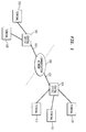
- Figure 1 shows a communication system that includes a backbone communication network 100, central offices 102 and 104 and terminals 106-112.
- the terminals 106-112 may be personnel computers, entertainment terminals such as televisions, or telephone stations such as telephones.
- the backbone communication network 100 may be fiber, wire or wireless systems. Trunks 101 and 103 forming the communication path between the central offices 102 and 104 and the backbone communication network 100 may be very high speed trunk lines. Currently, the communication paths between the central offices 102 and 104 and the respective terminals 106, 108 and 110, 111, 112 may be implemented by systems shown in Fig. 2 and 3 and as discussed below.
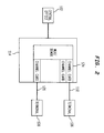
- FIG. 2 is a block diagram of a current telephone system implementation that connects the central office 102 to the terminals (telephones) 106 and 108 through a pedestal 114.
- the pedestal 114 includes a channel bank 124 of channel cards where each of the channel cards is dedicated to one of the terminals such as terminals 106 and 108. Thus each channel card is used only as often as the corresponding terminal is used. Since terminals 106 and 108 are typically used less than 75% of the time, the channel cards of the channel bank 124 are extremely under-utilized.
- the above inefficient use of resources as well as associated complex management of dedicated lines such as twisted pairs 118 and 120 are improved upon by a hybrid fiber/coax (HFC) communication system shown in Fig. 3.
- HFC hybrid fiber/coax
- the HFC system provides for Time Division Multiplexing (TDM) which permits a group of end users to share one or more frequency channels. Because multiple end users may share a single frequency channel, each RF modem may support multiple end users. Thus, the channel bank 124 of channel cards may be replaced by a smaller number of RF modems.
- TDM Time Division Multiplexing
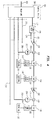
- the HFC system includes a head-end 105 which is coupled to a fiber node 128 through optical fiber 127.
- the fiber node 128 converts the optical signals received from the optical fiber 127 into electrical signals which are output to end users 140, 142 and 144 through coaxial networks.
- the coaxial signal line 131 is connected to the end users 140, 142 and 144 through amplifier 130, taps 134, 136 and 138, amplifier 132, coaxial signal lines 135, 137 and 139, and network interface units (NIU) 146, 148 and 150.
- Other taps and amplifiers downstream from tap 138 may also be connected to service additional end users.
- the taps 134, 136 and 138 are passive devices as are the coaxial lines 135, 137 and 139. These passive devices may support bandwidths up to about 1 Ghz. However, amplifiers such as amplifiers 130 and 132 have bandwidths that varies between about 350 to 750 Mhz. Thus, bandwidth limitation of the amplifiers 130 and 132 limits the downstream bandwidth of this HFC system.
- Upstream communication is made possible by enhancing the amplifiers to be bi-directional.
- upstream communication uses a frequency band from 5 to 40 Mhz and is susceptible to ingress noise.
- the head-end 105 may include a broadcast portion that broadcasts a video signal to the end users 140, 142 and 144. Because of the shared-bus architecture and the bandwidth constraint described above, the HFC system uses TDM and Time Division Multiple Access (TDMA) for switched and narrowcast services.
- TDMA Time Division Multiple Access
- Figure 4 shows an enhancement of the HFC system shown in Fig. 3.
- the conventional HFC, shown in Fig. 3 is enhanced by adding mini-fiber nodes (mFN) 202 and 204, diplexers 212 and 214, and associated elements to support communication between the end users 140, 142, 144 and the central office 104 and the trunk 103 through the mFNs 202 and 204.
- mini-fiber nodes mFN
- Each of the mFNs 202 and 204 is associated with one of the amplifiers 130 and 132.
- the mFN 202 is associated with the amplifier 130 and the mFN 204 is associated with the amplifier 132.
- the mFNs 202 and 204 are connected to the head-end 200 through optical fibers 206 and 208.
- Optical fibers 210 and 212 are connected to other mFNs that are not shown.
- Mini-fiber nodes 202 and 204 provide both downstream and upstream communication through the optical fibers 206 and 208.
- the mFNs 202 and 204 utilize clean and wide bandwidths at high frequencies beyond limitations of the amplifiers 130 and 132, avoiding upstream ingress noise and without affecting existing HFC system.
- the diplexer 212 sends an output signal to downstream end users 140 and 142 by combining the outputs of the amplifier 130 and the mFN 202.
- the diplexer 212 receives upstream communication from the end users 140 and 142 and sends the upstream communication to the mFN 202 to be output to the backbone communication network 100 through the optical fiber 206, the head-end 200 and the trunk 103.
- the optical fibers 206 and 208 may include one optical fiber or two optical fibers. If one optical fiber is used, both downstream and upstream communication use the same optical fiber. If two optical fibers are included, one optical fiber may be dedicated to downstream communication and the other optical fiber dedicated to upstream communication.
- Figure 4 shows only two amplifiers 130 and 132, two mFNs 202 and 204, two diplexers 212 and 214, and three taps 134, 136, and 138.
- any number of each of the above elements may be included and the fiber node 128 may also output to other coaxial signal lines such as the coaxial signal line 129 which may include additional amplifiers, diplexers, mFNs, taps, etc.
- the number and type of elements depends on the application circumstances.
- the mFNs 202 and 204 are coupled to the end users 140, 142 and 144 by only passive elements that have bandwidths of about 1 GHz, the usable bandwidth by end users 140, 142 and 144 is extended up to about 1 GHz without modifying the amplifiers 130 and 132. Thus, the mFNs 202 and 204 provide greater bandwidth unlimited by the bandwidths of amplifiers 130 and 132.
- the amplifiers 130 and 132 do not pass the signals handled by mFNs 202 and 204 for both downstream and upstream communications thus isolating the communication traffic of each of the mFNs 202 and 204.
- Filters may also be placed before each of the amplifiers 130 and 132 to further filter out mFN signals from being transmitted downstream. This isolation permits each of the mFNs 202 and 204 to operate independently of other mFNs 202 and 204.
- the mFNs 202 and 204 may utilize different frequency bands or share a common frequency band for both downstream and upstream communications. This bandwidth re-use significantly increases the available bandwidth per end user.
- Figure 4 is an exemplary embodiment for an mFN application.
- Other mFN applications may also benefit from the present invention such as the Express architecture disclosed in the U.S. Application Serial No. 08/526,736,
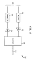
- FIG. 5 shows a block diagram of an exemplary embodiment of the mFN 202.
- the mFN 202 includes a receiver path and a transmitter path connected to a diplexer 226.
- the receiver 218 receives optical signals from the optical fiber 206 and converts the optical signals into electrical signals which are amplified by amplifier 222 and input into the diplexer 226.
- the diplexer 226 outputs the electrical signals directly to the diplexer 212.
- the diplexer 226 receives electrical signals from the diplexer 212 and outputs these signals to the amplifier 224.
- the amplifier 224 outputs the signals to the transmitter 220 and the transmitter 220 converts the electrical signals into optical signals and outputs the optical signals onto optical fiber 206.
- the diplexer 212 may be included in the mFN 202.
- the mFNs 202 and 204 provide significant advantages such as clean and wide bandwidths resulting in greater bandwidth per end user 140, 142 and 144. Because one mFN 202 and 204 is associated with one amplifier 130 and 132, the number of end users 140, 142 and 144 served by each mFN 202 and 204 is much smaller than the number of end users 140, 142 and 144 served by the fiber node 128. Thus, the bandwidth per mFN 202 and 204 serves fewer end users 140, 142 and 144.
- bandwidth sharing made possible by mutual isolation of the mFNs 202 and 204
- further additional bandwidth per end user 140, 142 and 144 is provided.
- This bandwidth increase allows the mFNs 202 and 204 to operate using Frequency Division Multiplexing/Frequency Division Multiple Access (FDM/FDMA) protocol instead of the more complex TDM/TDMA protocol.
- FDM/FDMA Frequency Division Multiplexing/Frequency Division Multiple Access
- head-end 200 is less complex than the head-end 105.
- Benefits of the above described mFN-HFC system may be applied to services such as telephony, data and entertainment services. In particular, one application is a simple telephone service.
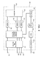
- FIG. 6 shows an exemplary embodiment of the head-end 200.
- the head-end 200 includes a mux/demux 230 connected to the trunk 103.
- the mux/demux 230 is connected to a pool of RF modems such as RF modems 232, 234 and 236.
- the RF modems 232, 234 and 236 are also connected to a frequency selector-converter-splitter 238 which is connected to the optical fiber 212, 206, 208 and 210 through transmitter and receiver block 242.
- the mux/demux 230 demultiplexes the data received from the trunk 103 into signals addressed to each end user.
- the demuxed signals are modulated onto an intermediate frequency carrier using modulation schemes such as Quadrature Phase Shift Keying (QPSK), Binary Phase Shift Keying (BPSK), or Quadrature Amplitude Modulation (QAM) by the RF modems 232, 234 and 236.
- modulation schemes such as Quadrature Phase Shift Keying (QPSK), Binary Phase Shift Keying (BPSK), or Quadrature Amplitude Modulation (QAM) by the RF modems 232, 234 and 236.
- the outputs of the RF modems 232, 234 and 236 are directed by the frequency selector-converter-splitter 238 to the mFNs 202 and 204 through the optical fibers 206 and 208.
- the head-end 200 allocates one channel that is dedicated to the end user 140 for this call.
- one of the RF modems 232, 234 and 236 is allocated for the dedicated channel.
- the output of the allocated RF modem is routed to the mFN 202 that serves the end user 140.
- the RF modems 232, 234 and 236 is allocated to the mFNs 202 and 204 to modulate the demuxed signals that is addressed to the end users 140, 142 and 144 served by the mFNs 202 and 204.
- the allocation of the modems 232, 234 and 236 to the mFNs 202 and 204 is controlled by a controller 240.
- the allocation of the RF modems 232, 234 and 236 to the mFNs 202 and 204 may be determined by either a predetermined plan or a dynamic allocation plan where the RF modems are allocated based on end user requirements (i.e., whether a particular end user served by an mFN has any communication traffic).
- the allocation information is stored in a data base 244 which is also controlled by the controller 240.
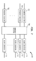
- FIG. 7 is a block diagram of an exemplary embodiment for the frequency selector-converter-splitter 238.
- the frequency selector-converter-splitter 238 maps in frequency the input/output signals of the RF modems 232, 234 and 236 and the mFNs 202 and 204.
- the mFN output signals are block converted by block converters 710, 712, 714 and 716 into different frequency bands before input to a combiner/splitter 708.
- the combiner/splitter 708 combines all the block converted frequency bands and outputs the combination to each of the frequency converters 702, 704 and 706.
- the output signals of the combiner/splitter 708 are frequency converted by frequency selectors 702, 704 and 706 to intermediate frequency signals before received as inputs by the RF modems 232, 234 and 236.
- the intermediate frequency signals output from the RF modems 232, 234 and 236 are frequency converted by the frequency selectors 702, 704 and 706 to selected frequencies based on the addressed end user.
- the frequency selectors 702, 704 and 706 further convert the selected frequencies to the frequency band allocated to the respective mFNs 202 and 204 to avoid frequency overlap of the mFN signals.
- the outputs of the combiner/splitter 708 are block converted by the block converters 710, 712, 714 and 716 from the allocated frequency band for each of the mFNs 202 and 204 to the frequency bands or the common frequency band used by the mFNs 202 and 204.
- the frequency-selector-converter-splitter 238 may be easily adapted based on other schemes to map the RF modems 232, 234 and 236 onto the mFNs 202 and 204 to optimize utilization of the RF modems 232, 234 and 236, the mFNs 1202 and 204, the frequency bands used by the mFNs 202 and 204 and the channels assigned to end users 140, 142, and 144.
- Figure 6 shows an RF modem organization that provides a pool of the RF modems 232, 234 and 236.
- an end user served by one of the mFNs 202 and 204 requests a channel
- one of the RF modems 232, 234 and 236 of the pool is allocated to the mFN 202 and 204 serving the requesting end user.
- the number of required RF modems 232, 234, and 236 may be reduced to a number that provides a level of communication service availability that is desired. Accordingly, pooling the RF modems 232, 234 and 236 exploits RF modem resources and increases RF modem utilization.
- Figure 8 shows a modification of the mFN connection to the head-end 200 of Fig. 6.
- All of the RF modems 232, 234 and 236 are pooled together in one modem bank 614 and the modem bank 614 is coupled to an optical fiber 624 through a frequency selector-splitter 616 and a transmitter and receiver 618.
- the optical fiber 624 may be a single fiber or a pair of fibers where one fiber serves downstream communication traffic and the other fiber serves upstream communication traffic.
- All of the mFNs 202 and 204 are connected to the optical fiber 624 through a splitter 622.
- the splitter 622 is optional because the mFNs 202 and 204 communicate on the optical fiber 624 using different frequency bands as further discussed below.
- the above modification connects a cluster of mFNs 202 and 204 to the central office 104 through the optical fiber 624.
- Figure 9 shows that the frequency selector-splitter 616 includes frequency selectors 702, 704 and 706 and a splitter 718.
- the frequency selector-splitter 616 is similar to the frequency selector-converter-splitter 238 except that the block converters 710, 712, 714 and 716 are not needed. Because all the mFN signals are transmitted or received on the optical fiber 624, the mFN signals are mapped into the allocated frequency bands by the frequency selectors 702, 704 and 706 and the transmitters 220 of the mFNs 202 and 204. The frequency selectors 702, 704 and 706 and the mFN receivers 218 receive signals from the allocated frequency bands.
- the frequency selectors 702, 704 and 706 convert the received signals into the intermediate frequencies for the RF modems 232, 234 and 236.
- the mFNs 202 and 204 convert the received signals to the respective frequency bands used by each mFN 202 and 204 or to the common frequency band used by all the mFNs 202 and 204.
- Fig. 8 The organization of Fig. 8 is advantageous for circumstances where optical fiber allocations for central office and mFN connections are very limited. For example, if mFN upgrades are applied to existing systems having only one available optical fiber between the central office 104 and mFNs 202 and 204, then the organization of Fig. 8 could be used.
- each of the mFNs 202 and 204 maintains independent channels.
- the logical function of the system as shown in Fig. 8 is the same as that shown in Fig. 6.
- the block converters 710, 712, 714 and 716 and the frequency selectors 702, 704 and 706 may include other elements such as filters.
- Figures 7 and 9 show only logical functions.
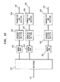
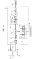
- FIG 10 shows the RF modems 232, 234 and 236 organized into modem banks 602, 604 and 606.
- Each of the modem banks 602, 604 and 606 is coupled to an optical fiber bus such as optical fiber buses 206, 208 and 210 through frequency selector-splitters 608, 610 and 612 and transmitter/receivers 624, 626 and 628, respectively.
- the frequency selector-splitters 608, 610 and 612 perform the same functions as the frequency selector-splitter 616 shown in Fig. 9.
- each of the modem banks 602, 604 and 606 is allocated to one of the mFNs 202 and 204. If the mFNs 202 and 204 are geographically located, the above organization guarantees that each geographic location has one bank of modems so that every geographical area is provided access to the backbone communication network 100 without being affected by the communication traffic volume of other geographical areas.
- FIG 11 shows a block diagram of an exemplary embodiment of the terminal 110 for the end user 140 that directly interfaces with the mFN 202 for telephone services.
- the mFN 202 is coupled to the coaxial signal line 135, through the diplexer 212 and the tap 134.
- the coaxial signal line 135 is a direct connection to the end user 140 and is connected to a splitter 250 located at the end user location.
- the splitter 250 splits out at least three kinds of signals; (1) the broadcast video signal which is output on signal line 252; (2) data signals, for Internet Communications, for example, are output and received on signal line 254; and (3) voice communication signals such as telephone communication are transmitted and received on signal line 256. Because the mFN 202 transmits and receives voice communication signals using the FDM/FDMA protocol, for example, the terminal 110, such as a telephone station, must interface with the mFN 202 by transmitting and receiving the voice communication signals in the FDM format.
- the terminal 110 includes an FDM unit 258 connected to a coder/decoder (codec) 262 through a modem 260.
- codec coder/decoder
- RF signals received from the mFN 202 are received by the FDM unit 258 and sent to the modem 260 which converts the signal into a form required by the codec 262.
- the codec 262 is connected to a speaker/microphone controller 264 which directly interfaces with the speaker/microphone 280 used by a user.
- the speaker/microphone controller 264 includes a ring/tone generator 276 and a signaling controller 278 that interfaces with the codec 262 to control the operation of the ring/tone generator 276 and the speaker/microphone 280.
- the terminal 110 (a telephone station for this example) also includes a conventional telephone interface 266 that interfaces with a terminal 282 that is a conventional telephone station. Because conventional telephone stations require twisted pairs interfaced to a channel card as shown in Fig. 2, the conventional terminal interface 262 performs the function of a channel card which includes a supervision unit 270, a battery 268, a ring/tone generator 272 and a line protection unit 274. Thus, the terminal 110 serves as a telephone station for a user to engage in voice communications directly through the speaker/microphone 280 as well as provides an interface for conventional telephone stations such as terminal 282 so that conventional telephone stations that a user may have can also be used.
- Figure 12 is a representative diagram of frequency channels in a FDM protocol.
- the bandwidth is divided into frequency channels such as frequency channels 302, 304, 306 and 308.
- Each of these frequency channels may be allocated to one of the end users 140, 142 and 144. However, because a specific end user may not utilize the allocated frequency channel 100% of the time, the frequency channels can be viewed as a pool of channels that may be allocated to an end user on a demand basis.
- Additional channels may be obtained by further dividing each frequency channel in time by time division multiplexing (TDM).
- TDM time division multiplexing
- a plurality of time slots such as time slot 402, 404 and 406 may be defined for frequency channel 310.
- a channel allocated to an end user is a particular time slot of a particular frequency channel such as time slot 402 of frequency channel 310.
- the bandwidth of a mFN 202 and 204 is used more efficiently.
- each of the channels may be preassigned to end users 140, 142, and 144 based on a predetermined plan. However, if the channels are assigned dynamically, the effective bandwidth may be further increased. However, dynamic allocation of channels requires additional protocols to determine channel allocation. Three alternative channel allocation protocols are discussed below and may be used to perform such channel allocations.
- the channels are first paired. One of each pair of channels is dedicated to downstream communication while the other of the pair of channels is dedicated to upstream communication. Thus, once a channel is allocated to an end user, both upstream and downstream channels are provided. In the following discussion, a channel will mean a pair of downstream/upstream channels. Protocols may also be implemented that allocates upstream and downstream channels separately.
- terminal 110 is a telephone station.
- the head-end controller 240 determines 1) which of the mFNs 202 and 204 serves the end user 140 and 2) a terminal ID addressed by the call.
- the above information is stored in the data base 244.
- the terminal ID is the identification number for the telephone station 110 such as a telephone number.
- the head-end controller 240 assigns a free channel to the call and formats the terminal ID and a channel number of the free channel into an alert message.
- the free channel is a frequency channel or a time slot of a frequency channel that is not used for other purposes.
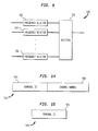
- An alert message 502 is shown in Fig. 14.
- the alert message 502 is transmitted downstream to the end user 140 on a preassigned signaling channel, for example.
- This signaling channel is not paired with another channel, but specifically allocated for the head-end controller 240 to send signaling information to all or a group of the end users 140, 142 and 144. All terminals of the end users 140, 142 and 144 monitor the signaling channel and a terminal addressed by the terminal ID 504 in the alert message 502 responds to the alert message 502 by executing appropriate processes.
- the telephone station 110 detects its terminal ID 504 in the alert message 502
- the telephone station 110 outputs a "ring" through either the speaker of the speaker/microphone unit 280 or through the ring/tone generator 272 to a ring device of the terminal 282. If the call is answered by taking the telephone station 110 or the terminal 282 off-hook, the telephone station 110 establishes a communication path through the channel having the channel number 506 received in the alert message 502.
- the telephone station 110 If the telephone station 110 is used to make a call by taking the telephone station 110 or the terminal 282 off-hook, the telephone station 110 must acquire an available channel through which to communicate before a dial tone can be output through the speaker of the speaker/microphone unit 280 or through the ring/tone generator 272 to the terminal 282.
- the telephone station 110 may acquire a channel by scanning through all possible channels to search for a "quiet" channel.
- a quiet channel is a channel that has no signal.
- the telephone station 110 may issue a channel request to the head-end 200 for using the located quiet channel.
- the channel request 508 may be issued upstream to the head-end controller 240 on the quiet channel.
- the channel request 508 contains only the terminal ID 504.
- the terminal ID 504 identifies the telephone station 110 so that the head-end controller 240 may assign an RF modem such as RF modems 232, 234 and 236 to the terminal ID 504 and route all data coming from the trunk 103 addressed to the terminal ID 504 to the allocated RF modem.
- the head-end may assign the quiet channel to the telephone station 110 by a loop-back process where the channel request 508 received on the upstream side of the quiet channel is looped back through the downstream side of the quiet channel to inform the telephone station 110 that the channel request 508 is granted.
- the telephone station 110 When the terminal ID 504 is detected on the downstream side of the quiet channel and matches the terminal ID of the telephone station 110, the telephone station 110 outputs a dial tone through the speaker of the speaker/microphone 280 or the terminal 282.
- the head-end may also loop-back the channel request 508 on a downstream signaling channel preassigned to the head-end 200.
- the loop-back process returns a combination of all the terminal IDs. Thus, none of the terminals will detect their specific terminal ID 504 and each terminal will search again for another quiet channel followed by another channel request 508. Each terminal repeats the above process until a channel is successfully obtained, or if unsuccessful for a preset number of tries, outputs a busy signal through the speaker of the speaker/microphone 280 or the telephone station 282.
- the head-end controller 240 may respond to a channel request 508 by explicitly assigning the quiet channel to the requesting terminal such as telephone station 110.
- the head-end controller 240 assigns the quiet channel to one of the terminal IDs by returning a granted message to the selected terminal ID 504 through either the quiet channel or the preassigned downstream signaling channel.
- the telephone station 110 proceeds with the communication process by outputting the dial tone through the speaker of the speaker/microphone 280 or conventional telephone station 282.
- the telephone station 110 may search for another quiet channel and repeat the channel request process. If a grant message is not received after a preset number of requests, the telephone station 110 may output a busy signal so that a user may be alerted that communication service cannot be provided at this time.
- the head-end controller 240 broadcasts channel availability information through the downstream signaling channel. This would alleviate the telephone station 110 from searching for a quiet channel which may cause undesirable delay.
- an available channel may be quickly determined by listening to the downstream signaling channel and a channel request 508 may be sent using the available channel or an upstream signaling channel that is preassigned for this purpose. If either the loop-back terminal ID or a grant message is received through either the downstream signaling channel or the available channel, the telephone station 110 may output a dial tone. Otherwise, the telephone station 110 may select another available channel by listening to the downstream signaling channel and issue another channel request 508. This process can continue until the head-end 200 indicates that no channels are available.
- the head-end 200 generates an availability signal on one of the channels.
- the telephone station 110 searches for the channel having the availability signal and transmits a channel request 508 using that channel or the upstream signaling channel. If the available channel is allocated to the telephone station 110, the head-end will either loop-back the terminal ID or send the grant message to the telephone station 110 through the available channel or the downstream signaling channel. After receiving either the loop-back terminal ID or the grant message, the telephone station 110 may proceed to output a dial tone. However, if either the loop-back terminal ID or the grant message is not received, the telephone station 110 may search for the next channel selected by the head-end 200 as the available channel. After the telephone station 110 occupy the available channel, the head-end 200 selects another channel and generates the availability information on the selected channel and the above process repeats.
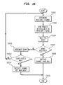
- FIG 16 shows a flow-chart of the channel allocation process discussed above.
- the telephone station 110 determines an available channel by one of the above three alternative methods. Then the process goes to step S1002.
- step S1002 the telephone station 110 sends a channel request on the available channel or a signaling channel. Then the telephone station 110 goes to step S1004.
- step S1004 the telephone station 110 waits for a grant message from the head-end 200 and then goes to step S1006.
- step S1006 the telephone station 110 determines whether a grant message was received. If a grant message was received, the telephone station 110 goes to step S1008. Otherwise, the telephone station 110 goes to step S1010.
- step S1010 the telephone station 110 increments a count and goes to step S1012.
- step S1012 the telephone station 110 determines whether the count exceeded a maximum. If the count exceeded a maximum, the telephone station 110 goes to step S1014. Otherwise, the telephone station 110 returns to step S1000.
- step S1014 the telephone station indicates that a channel is not available for communication by generating a busy tone, for example. Then the telephone station 110 goes to step S1016 and ends the process.
- step S1008 the telephone station 110 indicates that a channel is available by generating a dial tone, for example, and goes to step S1016 and ends the process.
- the present invention may be applied to any passive point to multipoint optical networks. Telephony, data and entertainment communication services may be provided on these networks which may benefit from the resource and channel allocation techniques of the present invention.
Abstract
Description
- This invention relates to a system and method for sharing resources in a communication system.
- While present communication systems provide adequate bandwidth to meet present demand for communication services, current communication infrastructure capacity may be exhausted in the near future as demand increases for data, entertainment and voice communications. Because of the high cost of equipment upgrades, new techniques are needed to exploit resources available in current systems or resources of anticipated system upgrades to further increase bandwidth availability either without costly additional equipment or permitting upgrades to be added in small increments as additional capacity is required.
- This invention provides a method and apparatus for pooling resources of a communication system to support nodes and end users serviced by the nodes. The nodes are coupled to a communications network through interface units that are organized into resource structures such as a pool. The interface units of the pool may be either preassigned to each of the nodes or may be allocated to the nodes based on end user requests.
- Communication channels are also organized into structures such as pools. End users may acquire communication services by requesting a channel. A channel may be a frequency channel of a frequency division multiplexing protocol or a time slot of a frequency channel such as provided by time division multiplexing protocol. Each end user may be either preassigned a channel or all the channels of a node may be organized into a pool and the channels are assigned to each end user as the user issues a request.
- The frequency bands used by the nodes may also be pooled. The nodes may be assigned different frequency bands from all available frequency ranges or all the nodes may share a common frequency band which is the combination of all the available frequency ranges. Each of the nodes is coupled to the backbone communication network through at least one dedicated channel. Thus, the bandwidth available to the end users is greatly expanded without expensive and complex upgrades to existing equipment.
- The invention will be described in connection with the following figures wherein like numerals represent like elements, and wherein:
- Fig. 1 is a diagram of a communication system;
- Fig. 2 is a block diagram showing a current communication system between a central office and end user terminals;
- Fig. 3 is a block diagram of a hybrid fiber/coax communication system;
- Fig. 4 is a block diagram of a hybrid fiber/coax system with mini-fiber nodes;
- Fig. 5 is a block diagram of a mini-fiber node of Fig. 4;
- Fig. 6 is a block diagram of a head-end of Fig. 4;
- Fig. 7 is a block diagram of a frequency selector-converter-splitter of Fig. 6;
- Fig. 8 is a block diagram of a modem bank organization for the head-end of Fig. 6;
- Fig. 9 is a block diagram of a frequency selector-converter of Fig.8;
- Fig. 10 is a diagram of another modem bank organization for the head-end of Fig. 6;
- Fig. 11 is a diagram of a terminal that communicates with the head-end of Fig. 4 via frequency division multiplexed signals;
- Fig. 12 is a diagram of frequency channels of a frequency division multiplexed protocol;
- Fig. 13 is a diagram of frequency channels of Fig. 12 also having time division multiplexed channels;
- Fig. 14 is a diagram of an alert message;
- Fig. 15 is a diagram of a channel request; and
- Fig. 16 is a flow chart of a channel request process.
- Figure 1 shows a communication system that includes a
backbone communication network 100,central offices - The
backbone communication network 100 may be fiber, wire or wireless systems. Trunks 101 and 103 forming the communication path between thecentral offices backbone communication network 100 may be very high speed trunk lines. Currently, the communication paths between thecentral offices respective terminals - Figure 2 is a block diagram of a current telephone system implementation that connects the
central office 102 to the terminals (telephones) 106 and 108 through apedestal 114. Thepedestal 114 includes achannel bank 124 of channel cards where each of the channel cards is dedicated to one of the terminals such asterminals terminals channel bank 124 are extremely under-utilized. The above inefficient use of resources as well as associated complex management of dedicated lines such astwisted pairs - The HFC system provides for Time Division Multiplexing (TDM) which permits a group of end users to share one or more frequency channels. Because multiple end users may share a single frequency channel, each RF modem may support multiple end users. Thus, the
channel bank 124 of channel cards may be replaced by a smaller number of RF modems. - Using the
central office 104 as an example, the HFC system includes a head-end 105 which is coupled to afiber node 128 throughoptical fiber 127. Thefiber node 128 converts the optical signals received from theoptical fiber 127 into electrical signals which are output toend users coaxial signal line 131 is connected to theend users amplifier 130, taps 134, 136 and 138,amplifier 132,coaxial signal lines tap 138 may also be connected to service additional end users. - The
taps coaxial lines amplifiers amplifiers - Upstream communication is made possible by enhancing the amplifiers to be bi-directional. However, upstream communication uses a frequency band from 5 to 40 Mhz and is susceptible to ingress noise.
- The head-
end 105 may include a broadcast portion that broadcasts a video signal to theend users - Figure 4 shows an enhancement of the HFC system shown in Fig. 3. U.S. Application Serial No. 08/526,736 filed on September 12, 1995, hereby incorporated by reference, provides a detailed description of the enhanced HFC system. In Fig. 4, the conventional HFC, shown in Fig. 3, is enhanced by adding mini-fiber nodes (mFN) 202 and 204,
diplexers end users central office 104 and thetrunk 103 through themFNs - Each of the
mFNs amplifiers mFN 202 is associated with theamplifier 130 and themFN 204 is associated with theamplifier 132. ThemFNs end 200 throughoptical fibers Optical fibers -
Mini-fiber nodes optical fibers mFNs amplifiers diplexer 212, for example, sends an output signal todownstream end users amplifier 130 and themFN 202. In addition, thediplexer 212 receives upstream communication from theend users mFN 202 to be output to thebackbone communication network 100 through theoptical fiber 206, the head-end 200 and thetrunk 103. - The
optical fibers - Figure 4 shows only two
amplifiers mFNs diplexers taps fiber node 128 may also output to other coaxial signal lines such as thecoaxial signal line 129 which may include additional amplifiers, diplexers, mFNs, taps, etc. The number and type of elements depends on the application circumstances. - Because the
mFNs end users end users amplifiers mFNs amplifiers - Since the frequency of the signals output by the
mFNs amplifiers amplifiers mFNs mFNs amplifiers mFNs other mFNs mFNs - Figure 4 is an exemplary embodiment for an mFN application. Other mFN applications may also benefit from the present invention such as the Express architecture disclosed in the U.S. Application Serial No. 08/526,736,
- Figure 5 shows a block diagram of an exemplary embodiment of the
mFN 202. ThemFN 202 includes a receiver path and a transmitter path connected to adiplexer 226. Thereceiver 218 receives optical signals from theoptical fiber 206 and converts the optical signals into electrical signals which are amplified byamplifier 222 and input into thediplexer 226. Thediplexer 226 outputs the electrical signals directly to thediplexer 212. Thediplexer 226 receives electrical signals from thediplexer 212 and outputs these signals to theamplifier 224. Theamplifier 224 outputs the signals to thetransmitter 220 and thetransmitter 220 converts the electrical signals into optical signals and outputs the optical signals ontooptical fiber 206. Thediplexer 212 may be included in themFN 202. - In summary, the
mFNs end user mFN amplifier end users mFN end users fiber node 128. Thus, the bandwidth permFN fewer end users - Moreover, due to bandwidth sharing made possible by mutual isolation of the
mFNs end user mFNs end 200 is less complex than the head-end 105. Benefits of the above described mFN-HFC system may be applied to services such as telephony, data and entertainment services. In particular, one application is a simple telephone service. - Because FDM/FDMA permits independent resource allocation for each
end user end 200 may be effectively achieved. For example, Fig. 6 shows an exemplary embodiment of the head-end 200. The head-end 200 includes a mux/demux 230 connected to thetrunk 103. The mux/demux 230 is connected to a pool of RF modems such as RF modems 232, 234 and 236. The RF modems 232, 234 and 236 are also connected to a frequency selector-converter-splitter 238 which is connected to theoptical fiber receiver block 242. - The mux/
demux 230 demultiplexes the data received from thetrunk 103 into signals addressed to each end user. The demuxed signals are modulated onto an intermediate frequency carrier using modulation schemes such as Quadrature Phase Shift Keying (QPSK), Binary Phase Shift Keying (BPSK), or Quadrature Amplitude Modulation (QAM) by the RF modems 232, 234 and 236. The outputs of the RF modems 232, 234 and 236 are directed by the frequency selector-converter-splitter 238 to themFNs optical fibers - When a call is received for an
end user 140, for example, the head-end 200 allocates one channel that is dedicated to theend user 140 for this call. To support the dedicated channel assigned to theend user 140, one of the RF modems 232, 234 and 236 is allocated for the dedicated channel. The output of the allocated RF modem is routed to themFN 202 that serves theend user 140. Thus, the RF modems 232, 234 and 236 is allocated to themFNs end users mFNs modems mFNs controller 240. - The allocation of the RF modems 232, 234 and 236 to the
mFNs data base 244 which is also controlled by thecontroller 240. - Figure 7 is a block diagram of an exemplary embodiment for the frequency selector-converter-
splitter 238. The frequency selector-converter-splitter 238 maps in frequency the input/output signals of the RF modems 232, 234 and 236 and themFNs mFNs block converters splitter 708. The combiner/splitter 708 combines all the block converted frequency bands and outputs the combination to each of thefrequency converters splitter 708 are frequency converted byfrequency selectors - In the downstream direction, the intermediate frequency signals output from the RF modems 232, 234 and 236 are frequency converted by the
frequency selectors frequency selectors splitter 708 are block converted by theblock converters mFNs mFNs - Other head-end resource allocation schemes than that described above are also possible. The frequency-selector-converter-
splitter 238 may be easily adapted based on other schemes to map the RF modems 232, 234 and 236 onto themFNs mFNs 1202 and 204, the frequency bands used by themFNs users - Figure 6 shows an RF modem organization that provides a pool of the RF modems 232, 234 and 236. When an end user served by one of the
mFNs mFN RF modems - Figure 8 shows a modification of the mFN connection to the head-
end 200 of Fig. 6. All of the RF modems 232, 234 and 236 are pooled together in onemodem bank 614 and themodem bank 614 is coupled to anoptical fiber 624 through a frequency selector-splitter 616 and a transmitter andreceiver 618. Theoptical fiber 624 may be a single fiber or a pair of fibers where one fiber serves downstream communication traffic and the other fiber serves upstream communication traffic. All of themFNs optical fiber 624 through asplitter 622. Thesplitter 622 is optional because themFNs optical fiber 624 using different frequency bands as further discussed below. Thus, the above modification connects a cluster ofmFNs central office 104 through theoptical fiber 624. - Figure 9 shows that the frequency selector-
splitter 616 includesfrequency selectors splitter 718. The frequency selector-splitter 616 is similar to the frequency selector-converter-splitter 238 except that theblock converters optical fiber 624, the mFN signals are mapped into the allocated frequency bands by thefrequency selectors transmitters 220 of themFNs frequency selectors mFN receivers 218 receive signals from the allocated frequency bands. Thefrequency selectors mFNs mFN mFNs - The organization of Fig. 8 is advantageous for circumstances where optical fiber allocations for central office and mFN connections are very limited. For example, if mFN upgrades are applied to existing systems having only one available optical fiber between the
central office 104 andmFNs - While signals of all the
mFNs optical fiber 624, each of themFNs optical fiber 624 is used, the logical function of the system as shown in Fig. 8 is the same as that shown in Fig. 6. Also, theblock converters frequency selectors - Figure 10 shows the RF modems 232, 234 and 236 organized into
modem banks modem banks optical fiber buses splitters receivers splitters splitter 616 shown in Fig. 9. In the above organization, each of themodem banks mFNs mFNs backbone communication network 100 without being affected by the communication traffic volume of other geographical areas. - Figure 11 shows a block diagram of an exemplary embodiment of the terminal 110 for the
end user 140 that directly interfaces with themFN 202 for telephone services. As shown in Fig. 4, themFN 202 is coupled to thecoaxial signal line 135, through thediplexer 212 and thetap 134. Thecoaxial signal line 135 is a direct connection to theend user 140 and is connected to asplitter 250 located at the end user location. Thesplitter 250 splits out at least three kinds of signals; (1) the broadcast video signal which is output onsignal line 252; (2) data signals, for Internet Communications, for example, are output and received onsignal line 254; and (3) voice communication signals such as telephone communication are transmitted and received onsignal line 256. Because themFN 202 transmits and receives voice communication signals using the FDM/FDMA protocol, for example, the terminal 110, such as a telephone station, must interface with themFN 202 by transmitting and receiving the voice communication signals in the FDM format. - Thus, the terminal 110 includes an
FDM unit 258 connected to a coder/decoder (codec) 262 through amodem 260. RF signals received from themFN 202 are received by theFDM unit 258 and sent to themodem 260 which converts the signal into a form required by thecodec 262. Thecodec 262 is connected to a speaker/microphone controller 264 which directly interfaces with the speaker/microphone 280 used by a user. The speaker/microphone controller 264 includes a ring/tone generator 276 and asignaling controller 278 that interfaces with thecodec 262 to control the operation of the ring/tone generator 276 and the speaker/microphone 280. - The terminal 110 (a telephone station for this example) also includes a
conventional telephone interface 266 that interfaces with a terminal 282 that is a conventional telephone station. Because conventional telephone stations require twisted pairs interfaced to a channel card as shown in Fig. 2, the conventionalterminal interface 262 performs the function of a channel card which includes asupervision unit 270, abattery 268, a ring/tone generator 272 and aline protection unit 274. Thus, the terminal 110 serves as a telephone station for a user to engage in voice communications directly through the speaker/microphone 280 as well as provides an interface for conventional telephone stations such asterminal 282 so that conventional telephone stations that a user may have can also be used. - Figure 12 is a representative diagram of frequency channels in a FDM protocol. Under FDM, the bandwidth is divided into frequency channels such as
frequency channels end users frequency channel 100% of the time, the frequency channels can be viewed as a pool of channels that may be allocated to an end user on a demand basis. - Additional channels may be obtained by further dividing each frequency channel in time by time division multiplexing (TDM). Thus, as shown in Fig. 13, a plurality of time slots such as
time slot frequency channel 310. When TDM and FDM protocols are used together, a channel allocated to an end user is a particular time slot of a particular frequency channel such astime slot 402 offrequency channel 310. Thus, when TDM and FDM are used together, the bandwidth of amFN - As discussed earlier, each of the channels may be preassigned to end
users - For all three alternative protocols, the channels are first paired. One of each pair of channels is dedicated to downstream communication while the other of the pair of channels is dedicated to upstream communication. Thus, once a channel is allocated to an end user, both upstream and downstream channels are provided. In the following discussion, a channel will mean a pair of downstream/upstream channels. Protocols may also be implemented that allocates upstream and downstream channels separately.
- For voice communication using telephones, for example, terminal 110 is a telephone station. When a call for the
end user 140 is received by the head-end 200, the head-end controller 240 determines 1) which of themFNs end user 140 and 2) a terminal ID addressed by the call. The above information is stored in thedata base 244. In this case the terminal ID is the identification number for thetelephone station 110 such as a telephone number. The head-end controller 240 assigns a free channel to the call and formats the terminal ID and a channel number of the free channel into an alert message. The free channel is a frequency channel or a time slot of a frequency channel that is not used for other purposes. Analert message 502 is shown in Fig. 14. - The
alert message 502 is transmitted downstream to theend user 140 on a preassigned signaling channel, for example. This signaling channel is not paired with another channel, but specifically allocated for the head-end controller 240 to send signaling information to all or a group of theend users end users terminal ID 504 in thealert message 502 responds to thealert message 502 by executing appropriate processes. Thus, when thetelephone station 110 detects itsterminal ID 504 in thealert message 502, thetelephone station 110 outputs a "ring" through either the speaker of the speaker/microphone unit 280 or through the ring/tone generator 272 to a ring device of the terminal 282. If the call is answered by taking thetelephone station 110 or the terminal 282 off-hook, thetelephone station 110 establishes a communication path through the channel having thechannel number 506 received in thealert message 502. - If the
telephone station 110 is used to make a call by taking thetelephone station 110 or the terminal 282 off-hook, thetelephone station 110 must acquire an available channel through which to communicate before a dial tone can be output through the speaker of the speaker/microphone unit 280 or through the ring/tone generator 272 to the terminal 282. Thetelephone station 110 may acquire a channel by scanning through all possible channels to search for a "quiet" channel. A quiet channel is a channel that has no signal. - Once the quiet channel is located, the
telephone station 110 may issue a channel request to the head-end 200 for using the located quiet channel. Thechannel request 508 may be issued upstream to the head-end controller 240 on the quiet channel. - An example of the
channel request 508 is shown in Fig. 15. Thechannel request 508 contains only theterminal ID 504. Theterminal ID 504 identifies thetelephone station 110 so that the head-end controller 240 may assign an RF modem such as RF modems 232, 234 and 236 to theterminal ID 504 and route all data coming from thetrunk 103 addressed to theterminal ID 504 to the allocated RF modem. - The head-end may assign the quiet channel to the
telephone station 110 by a loop-back process where thechannel request 508 received on the upstream side of the quiet channel is looped back through the downstream side of the quiet channel to inform thetelephone station 110 that thechannel request 508 is granted. When theterminal ID 504 is detected on the downstream side of the quiet channel and matches the terminal ID of thetelephone station 110, thetelephone station 110 outputs a dial tone through the speaker of the speaker/microphone 280 or the terminal 282. The head-end may also loop-back thechannel request 508 on a downstream signaling channel preassigned to the head-end 200. - If multiple channel requests are received from different terminal IDs including
terminal ID 504 for thesame channel number 506, then the loop-back process returns a combination of all the terminal IDs. Thus, none of the terminals will detect theirspecific terminal ID 504 and each terminal will search again for another quiet channel followed by anotherchannel request 508. Each terminal repeats the above process until a channel is successfully obtained, or if unsuccessful for a preset number of tries, outputs a busy signal through the speaker of the speaker/microphone 280 or thetelephone station 282. - The head-
end controller 240 may respond to achannel request 508 by explicitly assigning the quiet channel to the requesting terminal such astelephone station 110. The head-end controller 240 assigns the quiet channel to one of the terminal IDs by returning a granted message to the selectedterminal ID 504 through either the quiet channel or the preassigned downstream signaling channel. After receiving the grant message, thetelephone station 110 proceeds with the communication process by outputting the dial tone through the speaker of the speaker/microphone 280 orconventional telephone station 282. - If a grant message is not received for a predetermined amount of time, for example, the
telephone station 110 may search for another quiet channel and repeat the channel request process. If a grant message is not received after a preset number of requests, thetelephone station 110 may output a busy signal so that a user may be alerted that communication service cannot be provided at this time. - An alternative protocol would be as follows: the head-
end controller 240 broadcasts channel availability information through the downstream signaling channel. This would alleviate thetelephone station 110 from searching for a quiet channel which may cause undesirable delay. When thetelephone station 110 goes off-hook, an available channel may be quickly determined by listening to the downstream signaling channel and achannel request 508 may be sent using the available channel or an upstream signaling channel that is preassigned for this purpose. If either the loop-back terminal ID or a grant message is received through either the downstream signaling channel or the available channel, thetelephone station 110 may output a dial tone. Otherwise, thetelephone station 110 may select another available channel by listening to the downstream signaling channel and issue anotherchannel request 508. This process can continue until the head-end 200 indicates that no channels are available. - In a third alternative, the head-
end 200 generates an availability signal on one of the channels. When off-hook, thetelephone station 110 searches for the channel having the availability signal and transmits achannel request 508 using that channel or the upstream signaling channel. If the available channel is allocated to thetelephone station 110, the head-end will either loop-back the terminal ID or send the grant message to thetelephone station 110 through the available channel or the downstream signaling channel. After receiving either the loop-back terminal ID or the grant message, thetelephone station 110 may proceed to output a dial tone. However, if either the loop-back terminal ID or the grant message is not received, thetelephone station 110 may search for the next channel selected by the head-end 200 as the available channel. After thetelephone station 110 occupy the available channel, the head-end 200 selects another channel and generates the availability information on the selected channel and the above process repeats. - Figure 16 shows a flow-chart of the channel allocation process discussed above. In step S1000, the
telephone station 110 determines an available channel by one of the above three alternative methods. Then the process goes to step S1002. In step S1002, thetelephone station 110 sends a channel request on the available channel or a signaling channel. Then thetelephone station 110 goes to step S1004. - In step S1004, the
telephone station 110 waits for a grant message from the head-end 200 and then goes to step S1006. In step S1006, thetelephone station 110 determines whether a grant message was received. If a grant message was received, thetelephone station 110 goes to step S1008. Otherwise, thetelephone station 110 goes to step S1010. - In step S1010, the
telephone station 110 increments a count and goes to step S1012. In step S1012, thetelephone station 110 determines whether the count exceeded a maximum. If the count exceeded a maximum, thetelephone station 110 goes to step S1014. Otherwise, thetelephone station 110 returns to step S1000. - In step S1014, the telephone station indicates that a channel is not available for communication by generating a busy tone, for example. Then the
telephone station 110 goes to step S1016 and ends the process. In step S1008, thetelephone station 110 indicates that a channel is available by generating a dial tone, for example, and goes to step S1016 and ends the process. - While the invention has been described in conjunction with the specific embodiments outlined above, it is evident that many alternatives, modifications and variations will be apparent to those skilled in the art. For example, the present invention may be applied to any passive point to multipoint optical networks. Telephony, data and entertainment communication services may be provided on these networks which may benefit from the resource and channel allocation techniques of the present invention.
- In addition, while FDM and/or TDM protocols are used as examples, other protocols such as Code Division Multiplexing (CDM) and Wavelength Division Multiplexing (WDM) may also be used and gain similar benefits. Accordingly, the preferred embodiments of the invention as set forth above are intended to be illustrative, not limiting. Various changes may be made without departing from the spirit and scope of the invention as defined in the following claims.
Claims (31)
- A communication system, comprising:a control unit having a plurality of interface units; anda plurality of nodes, each of the nodes communicating with the control unit through at least one dedicated channel, wherein at least one of the interface units is allocated to any one of the nodes.
- The communication system of claim 1, wherein the interface units are coupled to the nodes through a single physical connection.
- The communication system of claim 1, wherein each of the nodes are associated with a corresponding plurality of end users, the nodes communicating information with the corresponding plurality of end users using a common frequency band.
- The communication system of claim 1, wherein the control unit assigns a channel to an end user based on a predetermined plan.
- The communication system of claim 1, wherein an end user sends a channel request to the control unit and the control unit grants a channel to the end user based on the channel request.
- The communication system of claim 5, wherein the end user searches for a quiet channel and sends the channel request to the control unit on one of the quiet channel and a signaling channel, the control unit sending a grant message to the end user on one of the quiet channel and the signaling channel to grant the quiet channel to the end user.
- The communication system of claim 5, wherein the control unit broadcasts available channel information on a signaling channel, the end user selecting an available channel as a selected channel and sending the channel request to the control unit on one of the selected channel and the signaling channel, the control unit sending a grant message to the end user to grant the selected channel to the end user.
- The communication system of claim 5, wherein the control unit broadcasts available channel information on a head-end channel, the end user sending the channel request to the control unit on one of the head-end channel and a signaling channel, the control unit sending a grant message to the end user to grant the head-end channel to the end user.
- The communication system of claim 5, wherein the channel includes a downstream channel and an upstream channel, the end user receiving information from the control unit through the downstream channel and sending other information to the control unit through the upstream channel.
- The communication system of claim 5, wherein if the control unit does not grant the channel to the end user, then the end user one of sends another channel request to the control unit and generates a busy signal.
- The communication system of claim 5, wherein the control unit loops back channel requests received on the channel, the channel being granted to the end user if the channel request sent by the end user is also received by the end user on the channel.
- The communication system of claim 5, wherein the control unit receives the channel request from the end user and other channel requests from other end users, if more than one end user requests the channel, the control unit selecting one of the more than one end user and grants the channel to the selected end user.
- The communication system of claim 5, wherein the control unit allocates one of the interface units to a node associated with the end user if an interface unit is not already allocated to the node, the control unit storing a correspondence between the allocated one of the interface units and the node as well as a correspondence between the end user and the granted channel in a memory device.
- The communication system of claim 5, wherein the control unit routes communications addressed to the end user through the allocated one of the interface units on the granted channel.
- The communication system of claim 1, wherein the control unit and the nodes are coupled by an optical fiber.
- A communication system, comprising:a control unit having a plurality of banks of interface units; anda plurality of nodes, each of the nodes communicating with the control unit through at least one dedicated channel, wherein at least one of the banks of interface units is allocated to each of the nodes.
- Method for operating a communication system, comprising:transferring information between a control unit and a plurality of nodes, the information being transferred between the control unit and each of the plurality of nodes through at least one dedicated channel; andallocating at least one of a plurality of interface units to any one of the nodes.
- The method of claim 17, further comprising:
coupling the interface units to the nodes through a single physical connection. - The method of claim 17, further comprising:
transferring data between the nodes and a plurality of end users associated with each of the nodes, wherein the data is transferred using a common frequency band. - The method of claim 17, further comprising:
assigning a channel to an end user associated with one of the nodes based on a predetermined plan. - The method of claim 17, further comprising:sending a channel request to the control unit to request a channel; andgranting the channel to an end user based on the channel request.
- The method of claim 21, further comprising:
searching for a quiet channel, wherein the channel request is sent on one of the quiet channel and a signaling channel, the control unit granting the quiet channel to the end user by sending a grant message on one of the quiet channel and a signaling channel. - The method of claim 21, further comprising:
broadcasting available channel information on a signaling channel, wherein the end user selects an available channel as a selected channel and sends the channel request on one of the selected channel and the signaling channel, the control unit sending a grant message to the end user to grant the selected channel to the end user. - The method of claim 21, further comprising:
broadcasting available channel information on a head-end channel, wherein the end user sending the channel request to the control unit on one of the head-end channel and a signaling channel, the control unit sending a grant message to the end user to grant the head-end channel to the end user. - The method of claim 21, further comprising:
sending another channel request to the control unit if the control unit does not grant the channel to the end user. - The method of claim 21, further comprising:
generating a busy signal if the control unit does not grant the channel to the end user. - The method of claim 21, further comprising:
receiving the channel request from the end user and other channel requests from other end users, wherein if more than one end user requests the channel, the control unit selects one of the more than one end user and grants the channel to the selected end user. - The method of claim 21, further comprising:
looping back channel requests received on the channel, the channel being granted to the end user if the channel request sent by the end user is received by the end user on the channel. - The method of claim 21, further comprising:allocating one of the interface units to a node associated with the end user if an interface unit is not already allocated to the node; andstoring a correspondence between the allocated one of the interface units and the node as well as a correspondence between the end user and the granted channel in a memory device.
- The method of claim 21, further comprising:
routing communications addressed to the end user through the allocated one of the interface units on the granted channel. - The method for operating a communication system, comprising:transferring information between a control unit and a plurality of nodes, the information being transferred between the control unit and each of the plurality of nodes through at least one dedicated channel; andallocating at least one of a plurality of banks of interface units to each of the nodes.
Applications Claiming Priority (2)
| Application Number | Priority Date | Filing Date | Title |
|---|---|---|---|
| US745764 | 1996-11-08 | ||
| US08/745,764 US6195362B1 (en) | 1996-11-08 | 1996-11-08 | Resource pooling system and method in communication systems |
Publications (2)
| Publication Number | Publication Date |
|---|---|
| EP0841829A2 true EP0841829A2 (en) | 1998-05-13 |
| EP0841829A3 EP0841829A3 (en) | 1999-11-03 |
Family
ID=24998159
Family Applications (1)
| Application Number | Title | Priority Date | Filing Date |
|---|---|---|---|
| EP97308395A Withdrawn EP0841829A3 (en) | 1996-11-08 | 1997-10-22 | Resource pooling system and method in communication systems |
Country Status (7)
| Country | Link |
|---|---|
| US (1) | US6195362B1 (en) |
| EP (1) | EP0841829A3 (en) |
| JP (1) | JPH10191482A (en) |
| CN (1) | CN1182994A (en) |
| AU (1) | AU727256C (en) |
| CA (1) | CA2218677C (en) |
| TW (1) | TW480854B (en) |
Cited By (1)
| Publication number | Priority date | Publication date | Assignee | Title |
|---|---|---|---|---|
| EP1502141A1 (en) * | 2002-04-24 | 2005-02-02 | Pangrac & Associates Development, Inc. | Fiber optic connector for a segmented ftth optical network |
Families Citing this family (37)
| Publication number | Priority date | Publication date | Assignee | Title |
|---|---|---|---|---|
| US6968379B2 (en) * | 1997-05-30 | 2005-11-22 | Sun Microsystems, Inc. | Latency-reducing bandwidth-prioritization for network servers and clients |
| US6542481B2 (en) | 1998-06-01 | 2003-04-01 | Tantivy Communications, Inc. | Dynamic bandwidth allocation for multiple access communication using session queues |
| US6151332A (en) | 1997-06-20 | 2000-11-21 | Tantivy Communications, Inc. | Protocol conversion and bandwidth reduction technique providing multiple nB+D ISDN basic rate interface links over a wireless code division multiple access communication system |
| US6081536A (en) | 1997-06-20 | 2000-06-27 | Tantivy Communications, Inc. | Dynamic bandwidth allocation to transmit a wireless protocol across a code division multiple access (CDMA) radio link |
| US6222832B1 (en) * | 1998-06-01 | 2001-04-24 | Tantivy Communications, Inc. | Fast Acquisition of traffic channels for a highly variable data rate reverse link of a CDMA wireless communication system |
| US7079523B2 (en) * | 2000-02-07 | 2006-07-18 | Ipr Licensing, Inc. | Maintenance link using active/standby request channels |
| US7936728B2 (en) * | 1997-12-17 | 2011-05-03 | Tantivy Communications, Inc. | System and method for maintaining timing of synchronization messages over a reverse link of a CDMA wireless communication system |
| US9525923B2 (en) | 1997-12-17 | 2016-12-20 | Intel Corporation | Multi-detection of heartbeat to reduce error probability |
| US7394791B2 (en) * | 1997-12-17 | 2008-07-01 | Interdigital Technology Corporation | Multi-detection of heartbeat to reduce error probability |
| US6381248B1 (en) * | 1998-01-27 | 2002-04-30 | At&T Corp. | Network architecture uses mini-fiber node and mini-coaxial node technologies to provide bi-directional broadband communications |
| JP4054477B2 (en) * | 1998-04-08 | 2008-02-27 | キヤノン株式会社 | COMMUNICATION DEVICE CAPABLE OF COMMUNICATION USING MULTIPLE COMMUNICATION CHANNELS TO THE SAME PARTY AND ITS CONTROL METHOD |
| US8134980B2 (en) * | 1998-06-01 | 2012-03-13 | Ipr Licensing, Inc. | Transmittal of heartbeat signal at a lower level than heartbeat request |
| US7221664B2 (en) | 1998-06-01 | 2007-05-22 | Interdigital Technology Corporation | Transmittal of heartbeat signal at a lower level than heartbeat request |
| US7773566B2 (en) | 1998-06-01 | 2010-08-10 | Tantivy Communications, Inc. | System and method for maintaining timing of synchronization messages over a reverse link of a CDMA wireless communication system |
| US6614776B1 (en) | 1999-04-28 | 2003-09-02 | Tantivy Communications, Inc. | Forward error correction scheme for high rate data exchange in a wireless system |
| US6526034B1 (en) | 1999-09-21 | 2003-02-25 | Tantivy Communications, Inc. | Dual mode subscriber unit for short range, high rate and long range, lower rate data communications |
| US7042895B1 (en) * | 1999-09-24 | 2006-05-09 | Agere Systems Inc. | Method and apparatus for interfacing multiple communication devices to a time division multiplexing bus |
| US8463255B2 (en) | 1999-12-20 | 2013-06-11 | Ipr Licensing, Inc. | Method and apparatus for a spectrally compliant cellular communication system |
| AU3673001A (en) | 2000-02-07 | 2001-08-14 | Tantivy Communications, Inc. | Minimal maintenance link to support synchronization |
| US6996132B1 (en) * | 2000-08-08 | 2006-02-07 | Verizon Laboratories Inc. | Method, apparatus and program for determining available bandwidth between multiple points in a communication system |
| US8155096B1 (en) | 2000-12-01 | 2012-04-10 | Ipr Licensing Inc. | Antenna control system and method |
| US7551663B1 (en) | 2001-02-01 | 2009-06-23 | Ipr Licensing, Inc. | Use of correlation combination to achieve channel detection |
| US6954448B2 (en) | 2001-02-01 | 2005-10-11 | Ipr Licensing, Inc. | Alternate channel for carrying selected message types |
| US7266298B2 (en) * | 2001-05-07 | 2007-09-04 | Aurora Networks, Inc. | N-way broadcast/narrowcast optical combiner demultiplexing a multiplexed narrowcast input signal |
| ES2614202T3 (en) | 2001-06-13 | 2017-05-30 | Intel Corporation | Method and apparatus for transmitting a heartbeat signal at a lower level than the request for heartbeat |
| US7406522B2 (en) * | 2001-09-26 | 2008-07-29 | Packeteer, Inc. | Dynamic partitioning of network resources |
| US7599283B1 (en) | 2003-06-30 | 2009-10-06 | Packeteer, Inc. | Network traffic synchronization and data compression in redundant network topologies |
| US7366101B1 (en) * | 2003-06-30 | 2008-04-29 | Packeteer, Inc. | Network traffic synchronization mechanism |
| JP4668843B2 (en) * | 2006-05-26 | 2011-04-13 | 富士通株式会社 | Radio base station receiver and program |
| US8793361B1 (en) | 2006-06-30 | 2014-07-29 | Blue Coat Systems, Inc. | Traffic synchronization across multiple devices in wide area network topologies |
| EP2074712B1 (en) * | 2006-10-03 | 2012-04-11 | ViaSat, Inc. | Web/bulk transfer preallocation of upstream resources in a satellite communication system |
| US9391921B1 (en) | 2008-03-18 | 2016-07-12 | Packeteer, Inc. | Virtual bandwidth management deployment architectures |
| JP5869276B2 (en) * | 2011-09-27 | 2016-02-24 | 株式会社日立製作所 | Resource management plan creation device and method, and program |
| EP2907335B1 (en) | 2012-10-15 | 2016-09-21 | Nec Corporation | Method and network system for supporting radio access network sharing |
| US9226123B2 (en) * | 2013-02-21 | 2015-12-29 | Telefonaktiebolaget L M Ericsson (Publ) | Limiting processing of calls as text telephony calls |
| US10225013B2 (en) * | 2016-12-01 | 2019-03-05 | Arris Enterprises Llc | Channel management to provide narrowcast data services using visible light communication |
| EP3334090A1 (en) * | 2016-12-08 | 2018-06-13 | InCoax Networks Europe AB | Method and system for synchronization of node devices in a coaxial network |
Citations (5)
| Publication number | Priority date | Publication date | Assignee | Title |
|---|---|---|---|---|
| US4789980A (en) * | 1986-08-18 | 1988-12-06 | American Telephone & Telegraph Company, At&T Bell Laboratories | Switching techniques for FDM communication systems |
| US5428608A (en) * | 1993-12-30 | 1995-06-27 | At&T Corp. | Call connection technique |
| EP0695092A1 (en) * | 1994-07-29 | 1996-01-31 | AT&T Corp. | Network apparatus and method for providing two-way broadband communications |
| EP0713347A2 (en) * | 1994-11-17 | 1996-05-22 | AT&T Corp. | Method and apparatus enabling STM and packet mode access on a broadband communications network |
| US5546383A (en) * | 1993-09-30 | 1996-08-13 | Cooley; David M. | Modularly clustered radiotelephone system |
Family Cites Families (9)
| Publication number | Priority date | Publication date | Assignee | Title |
|---|---|---|---|---|
| US4768188A (en) * | 1982-05-20 | 1988-08-30 | Hughes Network Systems, Inc. | Optical demand assigned local loop communication system |
| US4625308A (en) * | 1982-11-30 | 1986-11-25 | American Satellite Company | All digital IDMA dynamic channel allocated satellite communications system and method |
| FR2556532B1 (en) | 1983-12-09 | 1986-10-24 | Trt Telecom Radio Electr | METHOD FOR TWO-WAY RADIOCOMMUNICATION BETWEEN FIXED STATIONS AND MOBILE STATIONS |
| JPS6290045A (en) | 1985-10-16 | 1987-04-24 | Kokusai Denshin Denwa Co Ltd <Kdd> | Frequency assignment system in fdma communication system |
| US5285469A (en) | 1991-06-03 | 1994-02-08 | Omnipoint Data Corporation | Spread spectrum wireless telephone system |
| US5210771A (en) | 1991-08-01 | 1993-05-11 | Motorola, Inc. | Multiple user spread-spectrum communication system |
| GB9210971D0 (en) | 1992-05-22 | 1992-07-08 | Philips Electronics Uk Ltd | Telecommunications system |
| US5416778A (en) | 1992-06-26 | 1995-05-16 | U.S. Philips Corporation | Digital radio communication system and primary and secondary station for use in such a system |
| US5293382A (en) | 1993-03-01 | 1994-03-08 | Motorola, Inc. | Method for FDMA signal multiplexing and demultiplexing |
-
1996
- 1996-11-08 US US08/745,764 patent/US6195362B1/en not_active Expired - Lifetime
-
1997
- 1997-10-20 CA CA002218677A patent/CA2218677C/en not_active Expired - Fee Related
- 1997-10-22 EP EP97308395A patent/EP0841829A3/en not_active Withdrawn
- 1997-11-03 TW TW086116509A patent/TW480854B/en not_active IP Right Cessation
- 1997-11-06 AU AU44390/97A patent/AU727256C/en not_active Ceased
- 1997-11-07 JP JP9305386A patent/JPH10191482A/en active Pending
- 1997-11-07 CN CN97122231.2A patent/CN1182994A/en active Pending
Patent Citations (5)
| Publication number | Priority date | Publication date | Assignee | Title |
|---|---|---|---|---|
| US4789980A (en) * | 1986-08-18 | 1988-12-06 | American Telephone & Telegraph Company, At&T Bell Laboratories | Switching techniques for FDM communication systems |
| US5546383A (en) * | 1993-09-30 | 1996-08-13 | Cooley; David M. | Modularly clustered radiotelephone system |
| US5428608A (en) * | 1993-12-30 | 1995-06-27 | At&T Corp. | Call connection technique |
| EP0695092A1 (en) * | 1994-07-29 | 1996-01-31 | AT&T Corp. | Network apparatus and method for providing two-way broadband communications |
| EP0713347A2 (en) * | 1994-11-17 | 1996-05-22 | AT&T Corp. | Method and apparatus enabling STM and packet mode access on a broadband communications network |
Cited By (2)
| Publication number | Priority date | Publication date | Assignee | Title |
|---|---|---|---|---|
| EP1502141A1 (en) * | 2002-04-24 | 2005-02-02 | Pangrac & Associates Development, Inc. | Fiber optic connector for a segmented ftth optical network |
| EP1502141A4 (en) * | 2002-04-24 | 2005-05-25 | Pangrac & Associates Dev Inc | Fiber optic connector for a segmented ftth optical network |
Also Published As
| Publication number | Publication date |
|---|---|
| CA2218677C (en) | 2002-04-23 |
| JPH10191482A (en) | 1998-07-21 |
| TW480854B (en) | 2002-03-21 |
| AU727256B2 (en) | 2000-12-07 |
| CA2218677A1 (en) | 1998-05-08 |
| AU4439097A (en) | 1998-05-14 |
| CN1182994A (en) | 1998-05-27 |
| EP0841829A3 (en) | 1999-11-03 |
| US6195362B1 (en) | 2001-02-27 |
| AU727256C (en) | 2001-10-25 |
| MX9708492A (en) | 1998-05-31 |
Similar Documents
| Publication | Publication Date | Title |
|---|---|---|
| US6195362B1 (en) | Resource pooling system and method in communication systems | |
| US5756280A (en) | Multimedia distribution network including video switch | |
| US6507573B1 (en) | Data transfer method and system in low voltage networks | |
| US5822678A (en) | CATV network for transport of radio frequency signals | |
| JP2868434B2 (en) | Communication system and its operation method | |
| US6031845A (en) | Allocation of bandwidth to calls in a wireless telecommunications system | |
| US5767895A (en) | CATV telephone system | |
| US5408260A (en) | Customer premises ADSL signal distribution arrangement | |
| US6219840B1 (en) | Method for assigning communication resources in a communication system | |
| KR970702636A (en) | FREQUENCY AGILE BROADBAND COMMUNICATIONS SYSTEM | |
| KR19980063990A (en) | How to allocate and deallocate transmission resources within the local multipoint distribution service system | |
| JPH08316992A (en) | Dynamic channel assignment for data to be transmitted by cable television channel | |
| CN1094683C (en) | Method for avoiding interference in a cable telephony system | |
| JPH08172405A (en) | Radio communication system | |
| JPS60250736A (en) | Multi-direction time division radio communication system | |
| WO1997037442A1 (en) | Method for providing a plurality of services in a communication system | |
| JP2535940B2 (en) | Multi-directional multiplex communication system | |
| JPH0946667A (en) | Communication system | |
| MXPA97008492A (en) | System and method of set to share resources in communication system | |
| KR100224562B1 (en) | Apparatus for call restriction in a satellite communication system, and method thereof | |
| JPH1146198A (en) | Polling method and system | |
| JP3105763B2 (en) | Multi-way multiple access wireless communication system | |
| KR100224561B1 (en) | Apparatus for priority call in a satellite communication system, and method thereof | |
| JPH1032578A (en) | Communication system | |
| JP3056620B2 (en) | Communication system for digital cordless telephone |
Legal Events
| Date | Code | Title | Description |
|---|---|---|---|
| PUAI | Public reference made under article 153(3) epc to a published international application that has entered the european phase |
Free format text: ORIGINAL CODE: 0009012 |
|
| AK | Designated contracting states |
Kind code of ref document: A2 Designated state(s): DE FR GB |
|
| AX | Request for extension of the european patent |
Free format text: AL;LT;LV;RO;SI |
|
| PUAL | Search report despatched |
Free format text: ORIGINAL CODE: 0009013 |
|
| RIC1 | Information provided on ipc code assigned before grant |
Free format text: 6H 04Q 11/00 A, 6H 04M 11/06 B |
|
| AK | Designated contracting states |
Kind code of ref document: A3 Designated state(s): AT BE CH DE DK ES FI FR GB GR IE IT LI LU MC NL PT SE |
|
| AX | Request for extension of the european patent |
Free format text: AL;LT;LV;RO;SI |
|
| 17P | Request for examination filed |
Effective date: 20000413 |
|
| AKX | Designation fees paid |
Free format text: DE FR GB |
|
| STAA | Information on the status of an ep patent application or granted ep patent |
Free format text: STATUS: THE APPLICATION IS DEEMED TO BE WITHDRAWN |
|
| 18D | Application deemed to be withdrawn |
Effective date: 20030503 |