EP0841168A2 - Liquid discharging apparatus and cleaning system for the same - Google Patents
Liquid discharging apparatus and cleaning system for the same Download PDFInfo
- Publication number
- EP0841168A2 EP0841168A2 EP97119346A EP97119346A EP0841168A2 EP 0841168 A2 EP0841168 A2 EP 0841168A2 EP 97119346 A EP97119346 A EP 97119346A EP 97119346 A EP97119346 A EP 97119346A EP 0841168 A2 EP0841168 A2 EP 0841168A2
- Authority
- EP
- European Patent Office
- Prior art keywords
- liquid
- liquid discharging
- cleaning
- head
- cleaning means
- Prior art date
- Legal status (The legal status is an assumption and is not a legal conclusion. Google has not performed a legal analysis and makes no representation as to the accuracy of the status listed.)
- Granted
Links
- 238000004140 cleaning Methods 0.000 title claims abstract description 343
- 239000007788 liquid Substances 0.000 title claims abstract description 268
- 238000007599 discharging Methods 0.000 title claims abstract description 211
- 239000000049 pigment Substances 0.000 claims abstract description 10
- 229920001971 elastomer Polymers 0.000 claims description 35
- 239000005060 rubber Substances 0.000 claims description 35
- 239000000463 material Substances 0.000 claims description 27
- 229920006168 hydrated nitrile rubber Polymers 0.000 claims description 21
- 230000007246 mechanism Effects 0.000 claims description 18
- 230000004044 response Effects 0.000 claims description 18
- 230000005489 elastic deformation Effects 0.000 claims description 12
- 229920006311 Urethane elastomer Polymers 0.000 claims description 10
- 229920002943 EPDM rubber Polymers 0.000 claims description 7
- 230000002441 reversible effect Effects 0.000 claims description 6
- 238000009835 boiling Methods 0.000 claims description 2
- 239000012528 membrane Substances 0.000 claims description 2
- 239000000976 ink Substances 0.000 description 347
- 239000000356 contaminant Substances 0.000 description 41
- 238000011084 recovery Methods 0.000 description 36
- 235000019589 hardness Nutrition 0.000 description 33
- 238000007639 printing Methods 0.000 description 33
- 239000003595 mist Substances 0.000 description 27
- 238000000034 method Methods 0.000 description 25
- 230000008569 process Effects 0.000 description 23
- 238000011109 contamination Methods 0.000 description 22
- 230000006870 function Effects 0.000 description 21
- 239000011148 porous material Substances 0.000 description 16
- 239000000975 dye Substances 0.000 description 14
- 230000035515 penetration Effects 0.000 description 14
- 230000008901 benefit Effects 0.000 description 13
- 239000013013 elastic material Substances 0.000 description 12
- XLYOFNOQVPJJNP-UHFFFAOYSA-N water Substances O XLYOFNOQVPJJNP-UHFFFAOYSA-N 0.000 description 12
- 239000000701 coagulant Substances 0.000 description 11
- 238000000151 deposition Methods 0.000 description 11
- 230000008021 deposition Effects 0.000 description 10
- 239000000203 mixture Substances 0.000 description 9
- 239000000428 dust Substances 0.000 description 8
- 230000015271 coagulation Effects 0.000 description 7
- 238000005345 coagulation Methods 0.000 description 7
- 230000001788 irregular Effects 0.000 description 7
- 230000007423 decrease Effects 0.000 description 6
- 230000006866 deterioration Effects 0.000 description 6
- 238000001035 drying Methods 0.000 description 5
- 239000010410 layer Substances 0.000 description 5
- 229920002379 silicone rubber Polymers 0.000 description 5
- 230000000740 bleeding effect Effects 0.000 description 4
- 238000006243 chemical reaction Methods 0.000 description 4
- 239000003086 colorant Substances 0.000 description 4
- 230000000694 effects Effects 0.000 description 4
- 239000012466 permeate Substances 0.000 description 4
- 239000002904 solvent Substances 0.000 description 4
- 239000000758 substrate Substances 0.000 description 4
- 239000007795 chemical reaction product Substances 0.000 description 3
- MTHSVFCYNBDYFN-UHFFFAOYSA-N diethylene glycol Chemical compound OCCOCCO MTHSVFCYNBDYFN-UHFFFAOYSA-N 0.000 description 3
- 238000002474 experimental method Methods 0.000 description 3
- 230000007774 longterm Effects 0.000 description 3
- 230000002829 reductive effect Effects 0.000 description 3
- 239000011347 resin Substances 0.000 description 3
- 229920005989 resin Polymers 0.000 description 3
- 239000007787 solid Substances 0.000 description 3
- PEDCQBHIVMGVHV-UHFFFAOYSA-N Glycerine Chemical compound OCC(O)CO PEDCQBHIVMGVHV-UHFFFAOYSA-N 0.000 description 2
- 239000000980 acid dye Substances 0.000 description 2
- 239000007767 bonding agent Substances 0.000 description 2
- 229920006317 cationic polymer Polymers 0.000 description 2
- 230000003247 decreasing effect Effects 0.000 description 2
- 238000001704 evaporation Methods 0.000 description 2
- 230000008020 evaporation Effects 0.000 description 2
- 239000004744 fabric Substances 0.000 description 2
- 239000012634 fragment Substances 0.000 description 2
- 230000004048 modification Effects 0.000 description 2
- 238000012986 modification Methods 0.000 description 2
- 229920000642 polymer Polymers 0.000 description 2
- 229920002635 polyurethane Polymers 0.000 description 2
- 239000004814 polyurethane Substances 0.000 description 2
- 238000005086 pumping Methods 0.000 description 2
- 238000007790 scraping Methods 0.000 description 2
- 230000008719 thickening Effects 0.000 description 2
- 238000011144 upstream manufacturing Methods 0.000 description 2
- OKTJSMMVPCPJKN-UHFFFAOYSA-N Carbon Chemical compound [C] OKTJSMMVPCPJKN-UHFFFAOYSA-N 0.000 description 1
- 229920000459 Nitrile rubber Polymers 0.000 description 1
- SJEYSFABYSGQBG-UHFFFAOYSA-M Patent blue Chemical compound [Na+].C1=CC(N(CC)CC)=CC=C1C(C=1C(=CC(=CC=1)S([O-])(=O)=O)S([O-])(=O)=O)=C1C=CC(=[N+](CC)CC)C=C1 SJEYSFABYSGQBG-UHFFFAOYSA-M 0.000 description 1
- 229930182556 Polyacetal Natural products 0.000 description 1
- XSQUKJJJFZCRTK-UHFFFAOYSA-N Urea Chemical compound NC(N)=O XSQUKJJJFZCRTK-UHFFFAOYSA-N 0.000 description 1
- 238000010521 absorption reaction Methods 0.000 description 1
- 230000009471 action Effects 0.000 description 1
- 230000002411 adverse Effects 0.000 description 1
- HSFWRNGVRCDJHI-UHFFFAOYSA-N alpha-acetylene Natural products C#C HSFWRNGVRCDJHI-UHFFFAOYSA-N 0.000 description 1
- 238000003491 array Methods 0.000 description 1
- 238000005452 bending Methods 0.000 description 1
- 229960000686 benzalkonium chloride Drugs 0.000 description 1
- NTXGQCSETZTARF-UHFFFAOYSA-N buta-1,3-diene;prop-2-enenitrile Chemical compound C=CC=C.C=CC#N NTXGQCSETZTARF-UHFFFAOYSA-N 0.000 description 1
- 239000004202 carbamide Substances 0.000 description 1
- 229910052799 carbon Inorganic materials 0.000 description 1
- 230000001934 delay Effects 0.000 description 1
- 230000002542 deteriorative effect Effects 0.000 description 1
- LYCAIKOWRPUZTN-UHFFFAOYSA-N ethylene glycol Natural products OCCO LYCAIKOWRPUZTN-UHFFFAOYSA-N 0.000 description 1
- 239000000835 fiber Substances 0.000 description 1
- 239000002657 fibrous material Substances 0.000 description 1
- 239000010419 fine particle Substances 0.000 description 1
- 238000009472 formulation Methods 0.000 description 1
- 235000011187 glycerol Nutrition 0.000 description 1
- 238000011086 high cleaning Methods 0.000 description 1
- WGCNASOHLSPBMP-UHFFFAOYSA-N hydroxyacetaldehyde Natural products OCC=O WGCNASOHLSPBMP-UHFFFAOYSA-N 0.000 description 1
- 230000006872 improvement Effects 0.000 description 1
- 230000010365 information processing Effects 0.000 description 1
- 238000003475 lamination Methods 0.000 description 1
- 238000000465 moulding Methods 0.000 description 1
- 239000004745 nonwoven fabric Substances 0.000 description 1
- 229920006324 polyoxymethylene Polymers 0.000 description 1
- 239000011241 protective layer Substances 0.000 description 1
- 230000009467 reduction Effects 0.000 description 1
- 238000005549 size reduction Methods 0.000 description 1
- 239000013589 supplement Substances 0.000 description 1
- 239000004094 surface-active agent Substances 0.000 description 1
- 238000012360 testing method Methods 0.000 description 1
Images


Classifications
-
- B—PERFORMING OPERATIONS; TRANSPORTING
- B41—PRINTING; LINING MACHINES; TYPEWRITERS; STAMPS
- B41J—TYPEWRITERS; SELECTIVE PRINTING MECHANISMS, i.e. MECHANISMS PRINTING OTHERWISE THAN FROM A FORME; CORRECTION OF TYPOGRAPHICAL ERRORS
- B41J2/00—Typewriters or selective printing mechanisms characterised by the printing or marking process for which they are designed
- B41J2/005—Typewriters or selective printing mechanisms characterised by the printing or marking process for which they are designed characterised by bringing liquid or particles selectively into contact with a printing material
- B41J2/01—Ink jet
- B41J2/135—Nozzles
- B41J2/165—Preventing or detecting of nozzle clogging, e.g. cleaning, capping or moistening for nozzles
- B41J2/16517—Cleaning of print head nozzles
- B41J2/16535—Cleaning of print head nozzles using wiping constructions
- B41J2/16538—Cleaning of print head nozzles using wiping constructions with brushes or wiper blades perpendicular to the nozzle plate
-
- B—PERFORMING OPERATIONS; TRANSPORTING
- B41—PRINTING; LINING MACHINES; TYPEWRITERS; STAMPS
- B41J—TYPEWRITERS; SELECTIVE PRINTING MECHANISMS, i.e. MECHANISMS PRINTING OTHERWISE THAN FROM A FORME; CORRECTION OF TYPOGRAPHICAL ERRORS
- B41J2/00—Typewriters or selective printing mechanisms characterised by the printing or marking process for which they are designed
- B41J2/005—Typewriters or selective printing mechanisms characterised by the printing or marking process for which they are designed characterised by bringing liquid or particles selectively into contact with a printing material
- B41J2/01—Ink jet
- B41J2/21—Ink jet for multi-colour printing
- B41J2/2107—Ink jet for multi-colour printing characterised by the ink properties
- B41J2/2114—Ejecting transparent or white coloured liquids, e.g. processing liquids
Definitions
- the present invention relates to liquid discharging apparatuses and cleaning systems for the same, which discharges ink or liquids, such as printability improvers, onto recording media and capable of forming high quality images.
- the present invention is applicable to all the devices using recording media such as paper, cloth, unwoven fabric, and transparency sheets (OHP sheets).
- recording media such as paper, cloth, unwoven fabric, and transparency sheets (OHP sheets).
- Examples of the devices include business machines and mass-produced machines, such as printers, copying machines and facsimiles.
- Ink jet recording has been used in printers, copying machines and the like due to low operation noise, low operation cost, easy size reduction, and easy color printing.
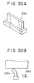
- Japanese Utility Model Laid-Open No. 58-128034 discloses, as shown in Fig. 30, a configuration for wiping the adhered ink and foreign matters such as powdered paper on the nozzle face 208b, in which the top end of an elastic plate blade 208a is in contact with the nozzle face 208b and wipes the nozzle face 208b in the direction of the arrow 208c. In such an ink jet head, however, the nozzle face 208b may be damaged due to rubbing with the powdered paper.
- a countermeasure to such a drawback is to form an indented nozzle face on the ink jet head so that the nozzle face and the other face portions do not form the same face.
- the above-mentioned flexible plate blade does not work well with the indented nozzle face as follows.
- Fig. 31A is a sectional view of a nozzle face of a recording head and two types of cleaning members
- Fig. 31B which is a front view of such a configuration when viewed from the bottom side in Fig. 31A.
- a cleaning member 209 consists of a first cleaning member 209a cleaning a nozzle face 209d which includes a nozzle 209e and a second cleaning member 209b cleaning ink-adhered portions 209c other than the nozzle face 209d.
- the first cleaning member 209a has a height which permits contact with the indented nozzle face 209d as shown in Fig. 31A and a width which is equal to the width of a nozzle array 209e as shown in Fig. 31B.
- the first cleaning member 209a moves in the direction of the arrow 209f and can clean the entire nozzle array 209e.
- the second cleaning member 209b has a height which permits contact with the ink-adhered portions 209c other than the nozzle face 209d as shown in Fig. 31A and can clean the ink-adhered portions 209c.
- the second cleaning member 209b consists of two fragments which are offset from the first cleaning member 209a in the direction of the arrow 209f and are arranged at both sides of the nozzle array 209e.
- Such a configuration having two types of cleaning members permits perfect cleaning of the nozzles and other faces of the recording head which do not form the same face.
- FIG. 32A is a sectional view of a nozzle face of a recording head and two types of cleaning members
- Fig. 32B which is a front view of such a configuration when viewed from the bottom side in Fig. 32A.
- a first cleaning member 210a shown in Figs. 32A and 32B is substantially equal to the first cleaning member 209a of the above-mentioned countermeasure.
- the second cleaning member 210b differs from the second cleaning member 209b of the above-mentioned countermeasure in that it is not divided into two fragments.
- wiping along the direction perpendicular to the nozzle array may adversely affect ink discharge characteristics.
- Typical examples of such cases include recording using a printability improving solution which instantaneously makes the dyes insoluble and coagulates dyes in the ink and recording using a pigment ink or the like in which fine particles are dispersed.
- Fig. 33 is a front view illustrating an ink discharging state by a recording head having a nozzle array for the printability improving solution, wherein 211a is a discharging head for the printability improving solution, 211b is an ink head or recording head, and 211c is a recording medium.
- the discharging head 211a for the printability improving solution has a solution nozzle array 211d, the ink head 211b has an ink nozzle array 211e, and these two heads are adjacent to each other in the scanning direction shown by the arrow 211i.
- the discharging head 211a for the printability improving solution discharges a droplet 211j of the printability improving solution on a predetermined position of the recording medium 211c to form an adhered layer 211k.
- an ink droplet 211l is discharged on the adhered layer 211k of the printability improving solution to form a coagulated region 211 m by instantaneous coagulation of the ink.
- Such a system can improve the image quality by preventing ink bleeding between different colors and by endowing waterproof properties.
- the ink is discharged onto the adhered layer 211k of the printability improving solution which is previously discharged on the recording medium 211c, hence a mixed mist 221l of the printability improving solution and the ink will rebound and adhere near the ink nozzle array 211e to form a coagulate 211h.
- Adhered layers 211f and 211g of the mists from the printability improving solution and the ink may also be formed on the nozzle arrays 211d and 211e, respectively.
- Fig. 34 is an enlarged plan view of the head shown in Fig. 33 from the recording medium side, which shows regions in which the mists from the ink and the printability improving solution adhere onto the faces including the ink nozzle array.
- the mist of the ink adheres to a region 211g near the nozzle array 211g during discharging the ink, whereas a mixed mist 211n of the printability improving solution and the ink adheres to the periphery of the nozzle array 211e to form the coagulate 211h.
- wiping is performed in the direction perpendicular to the nozzle array as shown in Figs. 31 and 32, the coagulate 211h shown in Fig.
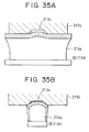
- Fig. 35A is an outlined front view of a flexible plate blade wiping the bottom of the indented head face 213c including the nozzle face
- Fig. 35B is an outlined front view of a small flexible plate blade wiping only the nozzle face at the bottom of the indented head face.
- the present inventors have tried wiping of the indented nozzle of the ink head along the longitudinal direction using a cleaner including a flexible wiper and a rubbing member disclosed in Japanese Utility Model Laid-Open No. 61-5647 and Japanese Patent Laid-Open No. 4-338552.
- the flexible wiper did not come into contact with the indented nozzle face.
- the present inventors therefore, have tried cleaning using only the rubbing member. Although this cleaning process is effective at an initial stage, the following drawbacks arise after repeated cycles of use.
- the water repellency of the face is perfectly lost by retransferring cycles, during which a large amount of printability improving solution adheres onto the face after aspiration.
- the deposited printability improving solution causes deflection of the discharged ink and deterioration of printing.
- the ink dye and fibrous materials also deposit on the nozzle face 208b of the ink jet recording head, as shown in Fig. 30, by evaporation of the solvent in the ink.
- a measure suitable for removing such contamination is a cleaning member composed of a porous wet elastic member disclosed in Japanese Utility Model Laid-Open No. 58-128034. Although the cleaner is smeared by repeated cleaning operation in such a cleaning system, hence the cleaning effect gradually decreases.
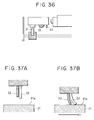
- FIG. 36 shows an ink jet recording apparatus provided with a wiper 32 and a cleaning means 33 proposed in Japanese Patent Laid-Open No. 2-518.
- Figs. 37A and 37B show an ink jet recording apparatus provided with a cleaner composed of a cleaning member 33 made of a wet porous elastic member and a protruded wiper 32 which is disclosed in Japanese Utility Model Laid-Open No. 61-5647.
- Figs. 38A, 38B and 38C show an ink jet recording apparatus provided with a cleaner disclosed in Japanese Patent Laid-Open No. 4-338552 in which a wiper 32 and a water absorbable cleaning member 33 are bonded to each other with a bonding agent 81.
- the cleaning means has a complicated configuration due to independent location of the wiper 32 and the cleaning member 33, hence the operation is also complicated. Since the stiffness of the cleaning member 33 is generally low, the cleaning member 33 must have a relatively large size in order to achieve a sufficient contact pressure by the cleaning member itself, and such a cleaning member 33 does not fit well to an irregular nozzle surface. In contrast, if the thickness of the cleaning member is reduced so that the cleaning member fits sufficiently to the nozzle surface, a satisfactory contact pressure cannot be achieved.
- the cleaning member 33 does not form a sufficient contact pressure and thus does not cause a satisfactory result. In some case, the cleaning member 33 is not wet enough to form a suitable contact pressure. Further, the cleaner is frequently used and requires high durability.
- the ink jet recording apparatus shown in Figs. 38A to 38C requires an additional step for bonding the cleaning member 33 and the wiper 32 and has drawbacks such as the durability of the joint between them and the selection of the bonding agent.
- the wiper 32 does not substantially come into contact with the nozzle face as in the case shown in Fig. 35.
- dust, powdered paper, ink droplets, sticky solid components formed by drying the ink and, in particular, a coagulate of the printability improving solution and the ink from the nozzle face can be easily removed from a long indented discharging face without deteriorating liquid discharging characteristics by wiping the face along the longitudinal direction, i.e., the nozzle array.
- a first aspect of the present invention is a liquid discharging apparatus using a liquid discharging head for discharging a liquid, comprising: a cleaning means for cleaning a nozzle section of the liquid discharging head, the cleaning means being formed of an elastic pillar member not absorbing the liquid and being elastically deformed when being in contact with a face including the nozzle section of the liquid discharging head.
- a second aspect of the present invention is a liquid discharging apparatus using a liquid discharging head for discharging a liquid, comprising: a plurality of cleaning means for cleaning a nozzle section of the liquid discharging head, at least one of the cleaning means comprising a rubbing member absorbing the liquid and an elastic plate member not absorbing the liquid, the rubbing member being in contact with a face including the nozzle section of the liquid discharging head in cooperation with elastic deformation of the elastic plate member when the cleaning means is in contact with the face.
- a third aspect of the present invention is a liquid discharging apparatus using a liquid discharging head for discharging a liquid, comprising: a plurality of cleaning means for cleaning a nozzle section of the liquid discharging head, each of the cleaning means comprising a first cleaning means composed of an elastic pillar member not absorbing the liquid and a second cleaning means comprising a rubbing member absorbing the liquid and an elastic plate member not absorbing the liquid.
- a fourth aspect of the present invention is a liquid discharging apparatus using a plurality of liquid discharging heads each having independent discharging mechanisms in response to different types of liquids, comprising: a plurality of cleaning means for cleaning nozzle sections of the liquid discharging heads, each of the cleaning means comprising an elastic pillar member being elastically deformed when in contact with a face including each of the nozzle sections of the liquid discharging heads.
- a fifth aspect of the present invention is a liquid discharging apparatus using a plurality of liquid discharging heads each having independent discharging mechanisms in response to different types of liquids, comprising: a plurality of cleaning means for cleaning nozzle sections of the liquid discharging heads, at least one of the cleaning means comprising a rubbing member absorbing one of the liquid and an elastic plate member not absorbing the corresponding liquid, the rubbing member being in contact with a face including each of the nozzle sections of the liquid discharging heads in cooperation with elastic deformation of the elastic plate member when the cleaning means is in contact with the face.
- a sixth aspect of the present invention is a liquid discharging apparatus using a plurality of liquid discharging heads each having independent discharging mechanisms in response to different types of liquids, comprising: a plurality of cleaning means for cleaning nozzle sections of the liquid discharging heads, each of the cleaning means comprising a first cleaning means composed of an elastic pillar member not absorbing one of the liquid and a second cleaning means comprising a rubbing member absorbing the corresponding liquid and an elastic plate member not absorbing the corresponding liquid.
- a seventh aspect of the present invention is a cleaning system for a liquid discharging apparatus comprising a cleaning means for cleaning a nozzle section of a liquid discharging head for discharging a liquid, the cleaning means being made of an elastic pillar member not absorbing the liquid and being elastically deformed when being in contact with a face including the nozzle section of the liquid discharging head.
- An eighth aspect of the present invention is a cleaning system for a liquid discharging apparatus comprising a plurality of cleaning means for cleaning a nozzle section of a liquid discharging head for discharging a liquid, at least one of the cleaning means comprising a rubbing member absorbing the liquid and an elastic plate member not absorbing the liquid, the rubbing member being in contact with a face including each of the nozzle sections of the liquid discharging heads in cooperation with elastic deformation of the elastic plate member when the corresponding cleaning means is in contact with the face.
- a ninth aspect of the present invention is a cleaning system for a liquid discharging apparatus comprising a plurality of cleaning means for cleaning a nozzle section of a liquid discharging head for discharging a liquid, each of the cleaning means comprising a first cleaning means composed of an elastic pillar member not absorbing the liquid and a second cleaning means comprising a rubbing member absorbing the liquid and an elastic plate member not absorbing the liquid.
- a tenth aspect of the present invention is a cleaning system for a liquid discharging apparatus comprising a plurality of cleaning means for cleaning nozzle sections of a plurality of liquid discharging heads each having independent discharging mechanisms in response to different types of liquids, each of the cleaning means comprising an elastic pillar member and being elastically deformed when being in contact with a face including each of the nozzle sections of the liquid discharging heads.
- An eleventh aspect of the present invention is a cleaning system for a liquid discharging apparatus comprising a plurality of cleaning means for cleaning nozzle sections of a plurality of liquid discharging heads each having independent discharging mechanisms in response to different types of liquids, at least one of the cleaning means comprising a rubbing member absorbing one of the liquid and an elastic plate member not absorbing the corresponding liquid, the rubbing member being in contact with a face including at least one of the nozzle sections of the liquid discharging heads in cooperation with elastic deformation of the elastic plate member when the corresponding cleaning means is in contact with the face.
- a twelfth aspect of the present invention is a cleaning system for a liquid discharging apparatus comprising a plurality of cleaning means for cleaning the nozzle sections of a plurality of liquid discharging heads each having independent discharging mechanisms in response to different types of liquids, each of the cleaning means comprising a first cleaning means composed of an elastic pillar member not absorbing one of the liquid and a second cleaning means comprising a rubbing member absorbing the corresponding liquid and an elastic plate member not absorbing the corresponding liquid.
- a thirteenth aspect of the present invention is liquid discharging apparatus comprising a cleaning means for cleaning a nozzle section of a liquid discharging head for discharging a liquid by contact with the nozzle section, wherein the cleaning means comprises an elastic member not absorbing the liquid and a rubbing member absorbing the liquid arranged in a linear row, the nozzle section is cleaned by at least the elastic member by means of relative movement in a given direction of the liquid discharging head and the cleaning means, and the rubbing member is supported by the elastic member from the rear side and nozzle section is cleaned by the rubbing member by means of relative movement in the opposite direction of the liquid discharging head and the cleaning means.
- Fig. 1 is an isometric partially broken away view of an ink jet recording apparatus including a liquid discharging apparatus as a first embodiment in accordance with the present invention.
- cartridges 1a for discharging liquids have reservoir sections provided on the upper section which store the liquids and heads provided under the reservoir sections which discharge the liquids onto recording paper 1i as a recording member.
- each cartridge 1a is electrically connected with a connector holder of the carriage 1b to transmit signals for driving the heads.
- the carriage 1b is supported by a scanning rail 1c, which extends in the moving direction of the recording paper 1i, that is, in the main scanning direction, and can be reciprocally slid by means of a driving belt 1d in the main scanning direction.
- the recording paper 1i is transferred by two pairs of carrying rolls, 1e and 1f, and 1g and 1h which are provided upstream and downstream from the recording position in which the head section of the cartridges is located.
- the transferring recording paper 1i is pressed by a platen (not shown in the drawing) which keeps the recording paper flat.
- the head section of the cartridges 1a loaded on the carriage 1b faces the recording surface (upper surface) of the recording paper 1i and protrudes such that it is located between the upstream carrying roll 1e and the downstream carrying roll 1g.
- the solution head discharges a printability improving solution and the ink heads discharge inks onto the recording medium. Since the printability improving solution instantaneously reacts with the inks and makes the dyes in the inks insoluble to solvents such as water on the recording medium, the dyes have become waterproof and bleeding between the different colors can be prevented.
- a recovery unit R is arranged at the home position HP on the left of Fig. 1.
- the recovery unit R has a plurality of cap units 1j corresponding to a plurality of cartridges 1a, and these cap units 1j are provided on a chassis C of the recording apparatus body and can be moved in the vertical direction by a moving mechanism not shown in the drawing.
- the cap units ij come into close contact with the heads of their respective cartridges 1a so as to cover the head section, and thus prevent unsatisfactory discharge of the inks due to thickening or drying of the inks in the nozzles on the head section.
- a pump unit 1k in the recovery unit R is connected to the cap units 1j and aspirates the nozzles on the head section through the cap units 1j being into close contact with the heads to generate a negative pressure when the heads do not successfully discharge the solution and the inks.
- a first blade 1l and a second blade 1m, which correspond to each cap unit 1j in the recovery unit R, are cleaning members for wiping the head section and are made of an elastic material such as rubber, and a blade holder 1n holds the first blade 1l and the second blade 1m.
- the blade holder 1n moves along the direction perpendicular to the main scanning direction of the carriage 1b, i.e., along the discharging face of the cartridge 1a and four first blades 1l, four second blades 1m on the left wipe their respective ink nozzle faces on the head section and the first blade 1l and the second blade 1m on the right wipes the solution nozzle face on the head section.
- an aqueous cationic polymer solution was used as a printability improving solution, and conventional inks containing acid dyes were used as recording inks.
- Table 1 shows a typical example of formulations of the printability improving solution and the recording inks.
- Figs. 2A to 2C are outlined front views for illustrating a wiping operation of the recovery unit R in the ink jet recording apparatus shown in Fig. 1.
- Numeral 2a is a wiper blade
- numeral 2b is a wiper blade holder
- numeral 2d is a rail for moving the wiper blade holder 2b, which extends in the direction (arrow 2e) perpendicular to the moving direction (arrow 2g) of the carriage.
- the head section of the cartridge 1a mounted on the carriage returns from the right side (the recording side) to the home position and stops at a position capable of wiping the head section.
- the blade holder 2b having the wiper blade 2a moves from the standby position in the direction of the arrow 2e so as to come into contact with the head section with a given contact pressure in order to wipe the face of the head section. After wiping, as shown in Fig.
- the recording head mounted on the carriage moves to the printing zone side in the direction of the arrow 2g so that the wiper blade 2a detaches from the face of the head section, and then the blade holder 2b returns to the standby position in the direction of the arrow 2f.
- the wiping operation is completed in such a manner.
- the paper travelling zone is separated from the wiping zone along the main scanning direction of the carriage, and the wiping direction is parallel to the paper travelling direction. If droplets of the inks and the printability improving solution adhered to the wiping blade are spattered due to elasticity of the wiping blade, the spattered ink rarely reaches the travelling zone of the recording medium and thus the recording medium can be protected from contamination.
- the wiping direction is not limited to the above-mentioned direction (the arrow 2e direction), and other wiping directions may be used.
- wiping in the direction of the arrow 2g and bi-directional wiping in the direction of the arrow 2g and the arrow 2e may be available.
- the wiper blade is made, with the aim of a stable long-term performance, of a material that cannot be deteriorated by the inks and the printability improving solution for long periods and cannot be easily broken during use for long periods.
- a material that cannot be deteriorated by the inks and the printability improving solution for long periods and cannot be easily broken during use for long periods.
- preferable materials include silicone rubbers, urethane rubbers, butadiene-acrylonitrile copolymers (HNBRs), and ethylene-propylene-diene terpolymers (EPDM rubbers).
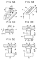
- FIG. 3A is an isometric view of a wiper blade of Example 1
- Fig. 3B is an isometric view of an ink jet recording head of Example 1
- Fig. 3C is a sectional view of an indented nozzle face taken from section X-X of Fig. 3B
- Figs. 3D to 3F are enlarged sectional views illustrating the wiping of the nozzle face of the head.
- the arrow A represents the edge of a hollow cylindrical wiper blade 2a which has a free length 3c. It is preferable that the outer diameter 3d of the wiper blade 2a be substantially equal to the width (3.0 mm in Fig. 3C) of the indented portion 3f of the head as shown in Fig. 3C. If the outer diameter of the wiper blade 2a is smaller than the width as shown in Fig. 3E, the wiper blade 2a can also be practically used when it comes into contact with the nozzles on the indented portion 3f. If the outer diameter of the wiper blade 2a is larger than the width, as shown in Fig. 3F, the wiper blade 2a can also be practically used when it comes into close contact with the nozzles on the indented portion 3f due to noticeable elastic deformation.
- the head face 3e in Fig. 3C functions as a capping face during aspiration.
- a long indented portion 3f is formed so as to be surrounded by the head face 3e and is provided with a nozzle array 3g along the longitudinal direction.
- the indented portion 3f does not have an arc cross-sectional view, as shown in Fig. 3C.
- the edge of the hollow cylindrical wiper is noticeably deformed due to the contact pressure and fits smoothly to the indented portion, hence the wiper ensures satisfactory cleaning of the indented portion including the angled corners unless the wiper does not have a shape which is equal to the sectional shape of the indented portion.
- the edge of the hollow cylindrical wiper is deformed to fit smoothly to the shape of the indented portion 3e and to wipe well the entire surface of the indented portion, if the center of the wiper is located between both edges of the indented portion.
- HNBR rubber is used for the hollow cylindrical wiper.
- the experimental results demonstrate that desirable characteristics are achieved by using a rubber having an HS(A) hardness in a range from 30° to 80°, and preferably from 55° to 75°.
- the HS(A) hardness is determined by JIS spring-type hardness test Model A in the present invention.
- Table 2 shows correlations between the contact load of the HNBR-rubber hollow cylindrical wiper and the penetration depth at various hardness levels in this example. The results shown in Table 2 demonstrate that the contact load substantially does not depend on the penetration depth in all the hardness levels of 55°, 65°, and 75°.
- the wiper having an HS(A) hardness of 55° and the wiper having an HS(A) hardness of 65° have very similar contact loads, and the wiper having an HS(A) hardness of 75° has a contact load which is about twice that of other wipers.
- the ink contamination can be satisfactorily removed by wiping under the contact load in the rubber having an HS(A) hardness of 55°, although a higher contact load is more effective for removing the contamination.
- the hollow cylindrical wiper having the above-mentioned size has a contact load in a range from 30 g to 60 g and the HNBR rubber as the wiper material has an HS(A) hardness in a range from 55° to 65°.
- the wiping speed of the hollow cylindrical wiper is preferably 5 mm/sec. to 50 mm/sec., and more preferably 5 mm/sec. to 20 mm/sec. under a contact load of 30 g to 60 g in order to achieve a high contamination-removing performance.
- the contamination-removing performance is affected by the curvature of the edge of the wiper which comes into contact with the head.
- Table 3 shows the wiping performance when the curvature of the edge is varied, in which the hollow cylindrical wiper is made of an HNBR rubber having an HS(A) hardness of 65°.
- a flash which is left on the edge or wall of the wiper will damage the edge of the nozzle during wiping, hence the ink or the printability improving solution will not be discharged satisfactorily.
- the curvature R of the wiper edge be 0.3 mm or less, and more preferably 0.1 mm or less and that the wiper edge has no flash as in Example 1.
- the wiper therefore must be formed in consideration of these results.
- the hollow cylindrical wiper in accordance with this embodiment can be deformed in all directions including the wiping direction, whereas the conventional plate wiper can be deformed only in the wiping direction.
- the wiper may be shifted relative to the head due to shifting of the stop position of the head and variation of the position of the wiper holder assembled in the apparatus.
- the hollow cylindrical wiper in accordance with this embodiment can be deformed to offset such a shift due to shifting of the stop position of the head and variation of the position of the wiper holder.
- the wiper can therefore wipe completely the entire indented nozzle face regardless of shifting between the wiper and the head.
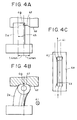
- a hollow cylindrical wiper having a height or free length 3c of 5.0 mm, an outer diameter 3d of 3.0 mm and an inner diameter of 1.4 mm is applied to a head, as shown in Fig. 3C, provided with a long indented portion with a length of 3.0 mm and a depth of 0.3 mm along the nozzle array at a penetration depth of the wiper to the head of 1.0 mm
- the edge of the hollow cylindrical wiper can be deformed to fit smoothly to the indented portion, as shown in Figs. 4B and 4C, within a relative shift distance of ⁇ 1.4 mm on both sides between the wiper and the head as shown in Fig. 4A.
- the hollow cylindrical wiper can fit smoothly into the indented portion when the center of the hollow cylindrical wiper is located between both ends of the indented portions.
- the shape and the size of the hollow cylindrical wiper and the material for the wiper are not limited to the above-mentioned example. Other shapes and sizes of the wiper and other materials having different HS(A) hardness levels may also be used in this invention. As described above, silicon rubbers, urethane rubbers and EPDM rubbers may also be used instead of the HNBR rubber used in this example.
- the wiping operation in the present invention may be performed after the recovery movement which starts after a predetermined number of dotting cycles for printing are repeated.
- the timing of the wiping operation is determined by the repeated dotting cycles just before the inks cannot be satisfactorily discharged due to coagulation of the mist mixture and deposition of the inks on the ink head face.
- the ink head face is wiped along the nozzle array using the hollow cylindrical wiper every 3.0 ⁇ 10 7 dotting cycles so as not to squeeze the deposition into the nozzles, in order to remove the deposition on the ink head face.
- the wiping operation is performed after exhausting the paper even if the given dotting cycles are counted during printing.
- the printability improving solution which reacts with the dyes of the inks, is used to make the dyes insoluble on the paper.
- the hollow cylindrical wiper in accordance with the present invention is also effective for systems using pigment inks which include carbon and the like and are deposited by drying on the ink head face.
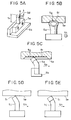
- Figs. 5A to 5E show a wiper of Example 2 in the liquid discharging apparatus in accordance with the present invention.
- Components having the same function as in Example 1 are referred to with the same identification numbers, and a detailed description thereof with reference to drawings has been omitted.
- the wiper of Example 2 can also be applied to the recording apparatus shown in Fig. 1.
- Fig. 5A is an isometric view of the wiper.
- the wiper has a hollow edge section indicated by arrow A and a free length 5c. It is preferable that the outer diameter 5d of the hollow edge section in Fig. 5A be substantially equal to the width of the indented portion of the head.
- the wiper blade can also be practically used when it comes into contact with the nozzles on the indented portion. If the outer diameter of the wiper blade is larger than the width, the wiper blade can also be practically used when it comes into close contact with the nozzles on the indented portion due to noticeable elastic deformation.
- Figs. 5B and 5C are a front view in the direction of the arrow 5h and a side view perpendicular to arrow 5h, respectively, illustrating the wiping operation by the wiper which moves along the long indented head portion having a non-arc section.
- the hollow edge section of the wiper of this example can be sufficiently deformed to fit smoothly to the indented portion due to the contact pressure during wiping, even if the shape of the hollow edge section does not fit into the indented portion when no contact pressure is applied.
- the edge face 5i does not come into contact with the head because the edge face 5i faces away from the head due to deformation during wiping as shown in Fig. 5D (hereinafter such wiping is referred to as forward wiping).
- the edge face 5i faces and comes into contact with the head due to deformation during wiping as shown in Fig. 5E (hereinafter such wiping is referred to as counter wiping).
- the counter wiping can more effectively remove contamination on the head face than the forward wiping under the same contact load.
- the counter wiping using the wiper of Example 2, as shown in Fig. 5E, is therefore suitable for removing a large amount of very sticky deposition composed of thickened or coagulated inks and the resin component of the printability improving solution compared with the forward wiping shown in Fig. 5d.
- wipers are made of HNBR rubbers of an HS(A) hardness of 55°, 65° and 75°, respectively.
- Table 4 shows correlations between the contact load of the HNBR-rubber wipers with hollow edge sections and the penetration depth at various HS(A) hardness levels in this example. The results shown in Table 4 demonstrate that the contact load depends on the penetration depth in all the HS(A) hardness levels of 55°, 65° and 75°.
- the parameters of the wiper must be optimized in consideration of the relative position between the wiper and the head so as to achieve satisfactory wiping results even under severe conditions.
- the wiper having an HS(A) hardness of 55° and the wiper having an HS(A) hardness of 65° have very similar contact loads, and the wiper having an HS(A) hardness of 75° has a contact load which is at least twice that of other wipers.
- the ink contamination can be satisfactorily removed by wiping under the contact load in the rubber having an HS(A) hardness of 55°, although a higher contact load is more effective for removing the contamination.
- the wiper which is made of HNBR rubber and has the above-mentioned shape and size has a contact load in a range from 50 g to 80 g and the HNBR rubber as the wiper material has an HS(A) hardness in a range from 60° to 80°.
- the wiping speed of the wiper is preferably 5 mm/sec. to 20 mm/sec. under a contact load of 30 g to 70 g in order to achieve a high contamination-removing performance.
- the shape, size, and HS(A) hardness of the above-mentioned wiper are described as an example, and are not limited in the present invention. Other shapes, sizes and HS(A) hardnesses of the wiper having a hollow edge section may also be used in this invention.
- silicon rubbers, urethane rubbers and EPDM rubbers may also be used instead of the HNBR rubber used in this example.
- the counter wiping in accordance with Example 2 can remove a large amount of very sticky deposition composed of thickened or coagulated ink and a resin component of the printability improving solution from the head face more effectively than the forward wiping. It is preferable that the speed of the counter wiping be in a range from 5 mm/sec. to 20 mm/sec. and the contact load be in a range from 30 g to 70 g.
- the contamination-removing performance is affected by the curvature of the edge of the wiper which comes into contact with the head.
- Table 5 shows the wiping performance when the curvature of the edge section is varied, in which the wiper is made by an HNBR rubber having an HS(A) hardness of 65°.
- the results shown in Table 5 demonstrate that the sticky contamination cannot be sufficiently removed by an edge section having a curvature R of 0.3 mm, but is effectively removed by an edge section having a curvature R of 0.1 mm when the wiping speed is in a range from 5 mm/sec. to 20 mm/sec. and the contact load is in a range from 30 g to 70 g.
- a flash which is left on the edge or wall of the wiper will damage the edge of the nozzle during wiping, hence the ink or the printability improving solution will not discharged satisfactorily.
- the curvature R of the edge section of the wiper be 0.1 mm or less and that the edge section has no flash as in Example 2.
- the wiper therefore must be formed in consideration of these results.
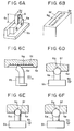
- Figs. 6A to 6F shows a wiper of a liquid discharging apparatus in Example 3 in accordance with the present invention.
- Fig. 5A is an isometric view of the wiper
- Fig. 5B is a recording head which has a long indented discharging face along the nozzle array and the indented face has an arc section.
- Fig. 5C is a front view illustrating the wiping of the indented face by moving the wiper in the direction of the arrow 6h
- Fig. 5D is a side view from the direction of arrow 6h which shows the contact state of the wiper and the head.
- Figs. 6E and 6F are side views illustrating the contact states of the wipers having different outer diameters and the heads.
- the wiper shown in Fig. 6A has a column shape which has an edge indicated by arrow A, a free length 6c, and an outer diameter 6d. It is preferable that the outer diameter 6d be substantially equal to the width of the indented head.
- the wiper blade can also be practically used when it comes into contact with the nozzles on the indented portion.
- the wiper blade can also be practically used when it comes into close contact with the nozzles on the indented portion due to noticeable elastic deformation.
- Figs. 7A to 7E show a wiper of a liquid discharging apparatus in Example 4 in accordance with the present invention.
- Fig. 7A is an isometric view of the wiper
- Fig. 7B is a front view illustrating wiping of the indented face by moving the wiper in the direction of the arrow 7h
- Fig. 7C is a side view from the direction of arrow 7h which shows the contact state of the wiper and the head.
- Figs. 7D and 7C are side views illustrating the contact states of the wipers having different outer diameters and the heads.
- the wiper shown in Fig. 7A has a polygonal column shape which has an edge indicated by arrow A, a free length 7c, and an outer diameter 7d so as to fit well to the indented head portion having the non-arc sectional shape as shown in Fig. 3C. It is therefore preferable that the outer diameter 7d be substantially equal to the width of the indented head portion.
- the wiper blade can also be practically used when it comes into contact with the nozzles on the indented portion.
- the wiper blade can also be practically used when it comes into close contact with the nozzles on the indented portion due to noticeable elastic deformation.
- Fig. 8 is an isometric partially broken away view of a liquid discharging apparatus in accordance with the Second Embodiment of the present invention.
- Two ink jet cartridges 1a are loaded on a carriage 1b provided with a connector holder which is electrically connected to the recording head to send signals for driving the recording head.
- the right cartridge contains a concentrated yellow, magenta and cyan ink and a diluted yellow, magenta and cyan ink separately
- the left cartridge contains a black ink and a printability improving solution separately.
- the carriage 1b is supported by a rail 1c which extends in the scanning direction of the carriage 1b.
- the carriage 1b is moved along the rail 1c by a driving belt 1d.
- the recording head portion of the ink jet cartridge 1a mounted on the carriage 1b protrudes downwards from the carriage 1b and is located between carrying rolls 1e and 1g for the recording medium, such that the nozzle face of the recording head portion faces and is parallel to the recording medium 1i which is put on the guide face of a platen not shown in the drawing.
- a recovery unit which will be described later is provided in a recovery unit section R at the home position side on the right in Fig. 8.
- the printability improving solution head discharges a printability improving solution onto a recording medium.
- the printability improving solution comes into contact with an ink discharged from the recording head and makes the dye in the ink insoluble to solvents such as water, hence the dye has waterproof characteristics. Since the printability improving solution simultaneously reacts with the dye in the ink, bleeding between different colors can also be prevented.
- the printability improving solution is composed of an aqueous cationic polymer solution and the recording ink is composed of an acid dye which has been generally used.
- Their composition is exemplified in Table 1.
- Fig. 9 is a sectional view illustrating the arrangement of a printability improving solution head and ink jet heads in this embodiment.
- Four ink jet cartridges provided with a printability improving solution head 12a, a black ink head 12b, a diluted color ink head 12c and a concentrated color ink head 12d, respectively, are mounted on a carriage 1b which moves in the direction of the arrow 12e during printing.
- a printability improving solution 12f, a black ink 12g, a diluted color ink 12h and a concentrated color ink 12i are discharged in that order from their respective heads onto the recording medium 1i.
- the quantity of mist rebounded to the ink jet head faces is different from each of the heads. That is, the quantity of rebounded mist of each ink is as follows: 12j > 12k > 12l wherein 12j is the quantity of the rebounded mist of the black ink, 12k is the quantity of the rebounded mist of the diluted color ink, and 12l is the quantity of the rebounded mist of the concentrated color ink.
- the contaminant of the head face is difficult to remove as the quantity of the deposited mist on the head face and the quantity of the printability improving solution in the deposited mist increase.
- the rank of such difficulty is as follows: black ink head > diluted color ink head > concentrated color ink head
- the contaminant on the face of the printability improving solution head has significantly different characteristics from those of the contaminants on the faces of the ink heads.
- these heads are provided with their respective optimized cleaning units in order to effectively remove (1) the contaminants, including rebounded mist, straying mist, mist formed during discharging the printability improving solution and inks, and powdered paper, which are deposited on these heads, have different characteristics; and (2) coagulant deposited on and near the nozzle edge.
- These optimized cleaning units have different configurations, but are provided with at least wiping members made of porous materials.
- each cleaning unit is provided with a cleaning section which delays deterioration of the porous wiping member, and a cleaning mechanism for cleaning the cleaning section.
- Figs. 10A and 10B are isometric views of an example of the recovery unit in accordance with the present invention.
- the recovery unit is provided with, from the left side, a cap 13a for the printability improving solution head, a cap 13b for the black ink head, a cap 13c for the diluted cyan, magenta and yellow ink head, and a cap 13d for the concentrated cyan, magenta and yellow ink head, in response to a plurality of ink jet cartridges 1a as shown in Fig. 8.
- the cap 13a for the printability improving solution head and the cap 13b for the black ink head have both aspiration and standby functions, whereas the cap 13c for the diluted cyan, magenta and yellow ink head and the cap 13d for the concentrated cyan, magenta and yellow ink head have only the standby function.
- the diluted cyan, magenta or yellow ink head and the concentrated cyan, magenta and yellow ink head are therefore aspirated by the cap 13b for the black ink head.
- These caps are held by cap levers 13f, 13g and 13h which are fixed to a recovery box 13e with an axle and turn on the axle by sliding on cam faces 13j of an aspiration cam 13i.
- the caps can therefore move upward or downward.
- the cap levers 13f, 13g and 13h are provided with A-ribs 13fA, 13gA and 13hA, respectively, which are snap-fitted to the indented sections B of the carriage 1b when capping the heads.
- the cap lever 13f for the printability improving solution cap is provided with a rib C and the ink jet cartridge 1a is provided with a rib D.
- the ribs C and D face each other when the concentrated color ink head 2d is covered with the cap 13b for aspiration-recovering treatment.
- the contact of the rib C with the rib D can prevent the contact of the cap 13a for the printability improving solution with the diluted color ink head 12c and thus the deposition of the reaction product of the printability improving solution with the recording ink on the face of the diluted color ink head 12c.
- the cap levers 13f and 13g are provided with cleaners 13fE and 13gE, respectively, which are members of a cleaner unit for cleaning the wiper unit, as described later.
- the caps 13a and 13b are connected to a pump unit 13k.
- the head is aspirated through the pump unit 13k in the recovery process after the recording head or the printability improving solution is covered with the cap unit.
- a tube pump is used for the pump unit 13k in this example.
- the pump unit includes tubes 13l and 13m, a roller holder 13n and a roller 13o.
- the roller holder 13n is fixed to the recovery box 13e by an axle and rotates on the axle.
- the roller 13o fixed to the recovery box 13e crushes the tubes 13l and 13m which are guided by the roller holder 13n to generate a negative pressure in the cap.
- the tube 13l is used for aspirating only the printability improving solution and the tube 13m is used for aspirating only the recording inks.
- the printability improving solution therefore does not react with the inks in the pumping unit, and pumping unit can be prevented from clogging due to deposition of the coagulated reaction products.
- a wiper unit 13p includes a rubbing section which is composed of water-absorbable rubbing members made of, for example, a porous material and plate wiper blades; a pillar cleaning member made of an elastic material such as rubber; and a blade holder for holding them.
- the wiper unit 13p is fixed to the recovery box 13e and can move in the transverse directions.
- wiper unit 13p The detailed configuration of the wiper unit 13p will be described with reference to Figs. 11A to 11C and Fig. 12.
- Rubbing members (hereinafter referred to as wiping members) 14a, 14b and 14c are made of a water-absorbable material such as a porous material.
- Plate wiper blades 14d, 14e and 14f are made of an elastic material such as rubber, and function as back pads for adjusting the contact loads of the wiping members to the head faces.
- the plate wiper blade is referred to as a back wiper.
- Each of pillar cleaning members 14g and 14h is made of an elastic material and has a cavity (hereinafter the pillar cleaning member 14g is referred to as a smart power blade (SPB), and the pillar cleaning member 14h is referred to as a smart blade (SB)).
- SPB smart power blade
- SB smart blade
- the above-mentioned cleaning members are mounted on a blade holder 14i.
- the cleaning members clean the printability improving solution head and the ink heads of the ink jet recording apparatus in accordance with the present invention shown in Fig. 8 accompanied by movement of the blade holder in the direction of the arrow 14j.
- the wiping members, back wipers, smart blade and smart power blade in the wiper unit effectively play their different roles in the recovery operation.
- the heights or free lengths of the wiping members, back wipers, smart blade and smart power blade from the base are equal to each other.
- the height or free lengths can be varied independently so that individual members further demonstrate their functions.
- each wiping member is placed on the corresponding back wiper in the drawings, these may be used after bonding them.
- the plate wiper blade 14d and the pillar cleaning members 14g and 14h can be made of an HNBR rubber, and the plate wiper blades 14e and 14f can be made of a urethane rubber.
- the wiping members 14a, 14b and 14c can be made of any porous material.
- the use of the HNBR rubber in the plate wiper blade 14d and the pillar cleaning member 14h is due to excellent durability to the printability improving solution and the use of the HNBR rubber in the pillar cleaning members 14g and 14h is due to excellent formability of such hollow molded articles.
- the hardnesses of the pillar cleaning members 14g and 14h can be different from each other, even if these are made of the same material.
- the pillar cleaning members 14g may have an HS(A) hardness of 65° and the pillar cleaning members 14h may have an HS(A) hardness of 55°. Since a hard material is suitable for the counter wiping, the pillar cleaning member 14g is harder than the pillar cleaning member 14h.
- the wiper unit 13p is provided with a rack 14k thereunder, and the rack 14k meshes with a gear 14l.
- the gear 14l and another gear 14m are mounted on the same axle, and the gear 14m meshes with a gear 14n which has a toothless section 14o and turns in cooperation with the aspiration cam 13i.
- the gear 14n turns clockwise with the aspiration cam 13i
- the gears 14m and 14l turn counterclockwise, and the rack 14k moves to the left in the direction of the arrow 14j.
- the wiper unit 13p therefore horizontally moves toward the recording heads and wipes these heads.
- the wiper unit 13p moves to and is cleaned by a cleaning unit for the wiper unit (will be shown in Figs. 13A to 13C in detail).
- a cleaning unit for the wiper unit will be shown in Figs. 13A to 13C in detail.
- the wiper unit 13p returns to the original position by means of the restoring force of an elastically deformed spring 14p.
- the wiper unit 13p wipes to clean the faces of the printability improving solution head and the ink heads at a given speed and a given contact pressure.
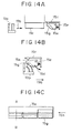
- Figs. 13A to 13C and Figs. 14A to 14C show a configuration and operation of a cleaning unit for the wiper unit of the recovery unit in accordance with the present invention.
- Fig. 13A is a sectional view illustrating an arrangement of the wiper unit 13p, the cap lever 13f (13g), a wiper unit cleaner 15a, the cleaner 13fE (13gE) and a recording head 15c when wiping is not performed.
- the configuration of this cleaning unit corresponding to the wiper unit section for cleaning the printability improving solution head and the wiper unit section for cleaning the black ink head and the diluted color ink head.
- the wiper unit cleaner 15a is fixed to a wiper unit cleaner piece 15f with an axle and turns on the axle. When the wiper unit cleaner 15a turns counterclockwise, a restoring force occurs by means of a spring 15e attached to the wiper unit cleaner piece 15f.
- the wiper unit cleaner 15a cannot turn clockwise due to the bent section of the wiper unit cleaner piece 15f. After the wiper unit 13p moves in the direction of the arrow 15b and wipes the recording head 15c, it is rubbed on the serrated wiper unit cleaner 15a as shown in Fig. 13B. Fig. 13B shows the wiper unit 13p in the midway of the moving path. The wiper unit 13p continues to move and the contaminants on the wiping members, back wipers, smart blade and smart power blade in the wiper unit 13p are scraped off. The wiper unit cleaner 15a turns counterclockwise in the direction of the arrow 15d and compresses the spring 15e.
- the wiper unit cleaner 15a After completing the cleaning process, the wiper unit cleaner 15a rapidly turns clockwise and the wiper unit 13p simultaneously moves away from the wiper unit cleaner 15a rapidly. Immediately after this, as shown in Fig. 13C, the cap lever 13f (13g) fixed to the recovery box 13e with an axle lifts so that the cleaner 13fE (13gE) comes into close contact with the serrated wiper unit cleaner 15a. The contaminants adhered to the serrated wiper unit cleaner 15a are transferred to the cleaner 13fE (13gE). In Figs. 13A to 13C, the wiper unit cleaner 15a corresponds to section A-B in Fig. 14C.
- the wiper unit cleaner 15a may be made of a resin, such as polyacetal, by a molding process.
- a resin such as polyacetal
- Preferable materials for the cleaner 13fE (13gE) includes porous polyurethanes, such as Rubycell ET (trade name).
- Fig. 14 shows an arrangement of the wiper unit 13p, the wiper unit cleaner 15g, which is made of a porous material, such as Sunfine (trade name), and the recording head 15c when wiping is not performed.
- This cleaner unit cleans the wiper unit section which cleans the concentrated color ink head.
- the wiper unit cleaner 15g is bonded to a wiper unit cleaner substrate 15a which is fixed to the wiper unit cleaner piece 15f with an axle so as to turn on the axle.
- a restoring force occurs by means of a spring 15e attached to the wiper unit cleaner piece 15f.
- the wiper unit cleaner 15g cannot turn clockwise due to the bent section of the wiper unit cleaner piece 15f.
- Fig. 14B shows the wiper unit 13p in the midway of the moving path.
- the wiper unit 13p continues to move and the contaminants on the wiping member in the wiper unit 13p are scraped off.
- the wiper unit cleaner 15g turns counterclockwise in the direction of the arrow 15d and compresses the spring 15e. After completing the cleaning process, the wiper unit cleaner 15g rapidly turns clockwise and the wiper unit 13p simultaneously moves away from the wiper unit cleaner 15g rapidly.
- Fig. 14C is a sectional view of the wiper unit cleaner substrate 15a and the wiper unit cleaner 15g when viewed from the wiper unit 13p. In Figs. 14A and 14B, the wiper unit cleaner substrate 15a and the wiper unit cleaner 15g are viewed from the arrow 15h in Fig. 14C.
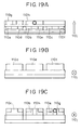
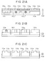
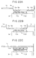
- Figs. 15A to 15C shows the operation for cleaning the printability improving solution head and the ink jet heads of the ink jet recording apparatus shown in Fig. 8 using the cleaning means shown in Figs. 11 and 12.
- the heads are separated from the cleaning means to illustrate clearly the configuration of the present invention, the heads actually come into close contact with the cleaning means at some places perpendicular to the moving direction of the carriage (in the direction of the arrow 14j). The same relationship holds in Figs. 22A to 22C and Fig. 23 described later.
- the carriage 12e After a given number of ink droplets are discharged from the printability improving solution head 12a or the black ink head 12b, the carriage 12e returns from the recording zone on the left in Fig. 8 to the home position and stops at a position which permits wiping as shown in Fig. 15A. Also, the carriage 12e stops at this position immediately after the aspiration process is completed.
- the blade holder 14i moves in the direction of the arrow 14j at a given speed and cleans the faces of the printability improving solution head 12a and the black ink head 12b.
- the carriage 12e moves to a position shown in Fig. 15B and stops there.
- the blade holder 14i moves in the direction of the arrow 14j at a given speed and cleans the faces of the diluted color ink head 12c and the concentrated color ink head 12d. That is, the wiping member 14a, the back wiper 14d and the smart power blade 14g clean the printability improving solution head 12a, and the wiping member 14b, the back wiper 14e and the smart blade 14h clean the black ink head 12b and the diluted color ink head 12c. Further, the wiping member 14c and the back wiper 14f clean the concentrated color ink head 12d.
- a wiper for exclusively cleaning the nozzle face of the printability improving solution head 12a may be provided in addition to the above-mentioned cleaning means.
- this exclusive wiper moves in the direction perpendicular to the nozzle array in the cleaning process (a so called transverse cleaning type).
- the transverse cleaning type of the exclusive wiper can ensure removal of the residual contaminants which are unavoidably left after cleaning by the above-mentioned cleaning means.
- the exclusive wiper is operated, for example, when a recording process to a sheet of recording paper is completed.
- the wiping direction is the same as the carrying direction of the recording medium, the droplets adhered to the blade due to wiping will barely spatter on the carrying section of the recording medium.
- the recording medium can therefore be prevented from unexpected contamination.
- the direction of cleaning is not limited to the above-mentioned direction. Wiping in different directions may be also available in order to enhance the wiping efficiency. For example, wiping from the back side to the front side in the drawings and reciprocal wiping are also effective.
- the cleaning means is cleaned immediately after wiping, hence the cleaning means can maintain a high cleaning efficiency for very long periods.
- the back wiper, smart blade and smart power blade must be made of materials which are resistant to deterioration due to inks and printability improving solutions and damage due to mechanical stress in repeated cycles of use for long periods, in order to ensure long-term stable performance.
- preferable materials for such a purpose include silicone rubbers, urethane rubbers, HNBR rubbers, and EPDM rubbers.
- the back wiper and smart power blade for the printability improving solution head be made of HNBR rubbers which are barely deteriorated and deformed by the contact for long periods with the printability improving solution.
- the wiping member in the present invention must be made of a material which is resistant to deterioration due to inks and printability improving solutions and damage due to mechanical stress in repeated cycles of use for long periods, in order to ensure long-term stable performance.
- preferable materials for such a purpose include porous polyurethanes such as Rubycell (trade name).
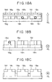
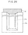
- Fig. 16A is an isometric view of the wiping member and the back wiper mounted on the blade holder.
- Numeral 17a is a water-absorbable porous wiping member and numeral 17b is a back wiper.
- the nozzle face of the head is indented from the capping face. Since the wiping member 17a is provided with cutout sections 17c at upper corners, the indented nozzle face is cleaned by the wiping member 17a and the capping face is cleaned by the back wiper 17b.
- Such a configuration of the porous wiping member is determined based on the cleaning effect as follows.
- the face is almost occupied by the remnant region 17g and the recovered region 17f is left only near the nozzle array.
- the recovered region 17f will not occur when the nozzles do not contain the ink or the printability improving solution. If the printing and recovery processes are repeated under such conditions, the quality of the printed images gradually deteriorates due to irregular ink discharge or clogging.
- the face When the moving speed is significantly low, the face is substantially occupied by the recovered region 17f and the remnant region 17g occurs only on the periphery of the face. Irregular ink discharge or clogging was not observed after the printing and recovery processes were repeated under such a condition. Accordingly, the inks and the printability improving solution can be stably discharged from the nozzles when a sufficiently wide recovered region 17f is formed so as to surround the nozzle array.
- the wiping mechanism for illustrating the above-mentioned phenomena is as follows.
- the ink in the nozzle is not absorbed into the porous member during the wiping process of the face, the contaminant trapped into fine pores on the surface of the porous member is partially retransferred onto the face by the contact pressure applied to the porous wiping member, hence a sufficiently wide recovery region does not occur.
- the wiping member 17a cleans, as shown in Fig. 16E, the indented nozzle face 17i in which the ink is sufficiently absorbed by the wiping member 17a and supplied from the nozzle, and both corners of the back wiper 17b scrape the remnants from the capping face 17j.
- Fig. 16F is a view illustrating the wiping of the nozzle face 17i, viewed from the direction of the arrow 17k in Fig. 16E.
- Fig. 16F demonstrates that the wiping member 17a fits well into the indented nozzle face 17i to ensure the wiping.
- the wiping member has other advantages. It is difficult to remove dust adhered to the edge of the nozzle and contaminants having high viscosity, such as coagulations of the printability improving solution and the inks, with an elastic wiper blade, and the contaminants may be squeezed into the nozzles by the wiper blade in some cases. Since the pore size of the porous wiping member is smaller than the diameter of the nozzle, the dust and the contaminants on the nozzle edges are scraped and trapped by these fine surface pores.
- Rubycell used as a material for the wiping member provides excellent advantages under the following conditions.
- the wiping member has excellent wiping characteristics in a thickness ranging from 0.5 mm to 3.0 mm, and preferably 1.0 mm to 2.0 mm; and a wiping load ranging from 10 g to 70 g, and preferably 10 to 40 g.
- the wiping load is adjusted according to the thickness of the wiping member and the thickness and HS(A) hardness of the back wiper.
- excellent characteristics can be achieved at a wiping rate in a range of from 5 mm/sec. to 30 mm/sec., and preferably 5 mm/sec. to 20 mm/sec.
- Wiping member Back wiper Material Rubycell ET (trade name) HNBR rubber Urethane rubber HS(A) hardness - 55° 75° a: Height 4.0 mm 4.0 mm 4.0 mm b: Width 12.0 mm 12.0 mm 12.0 mm c: Contact width 6.0 mm 12.0 mm 12.0 mm d: Cut width 3.0 mm - - e: Cut height 2.0 mm - - f, f': Thickness 1.5 mm 0.5 mm 0.5 mm g: Free length 4.0 mm 4.0 mm 4.0 mm mm h: Penetration depth 1.0 mm 1.0 mm 1.0 mm Used head Both heads Solution head Ink head
- Symbols a to h in Table 6 represent the sizes of the wiping member and the back wiper as shown in Figs. 17A and 17B.
- the deposition of the coagulant and thickened ink and retransfer of the deposition onto the face are accelerated in proportion to the total quantity of the rebounded mist and the quantity of the printability improving solution contained in the mist.
- the rank of possibility of retransfer in the ink jet recording apparatus in accordance with the present invention is as follows: black ink head > diluted color ink head > concentrated color ink head Such a drawback is improved by the cleaning means shown in Figs. 11 and 12 as described as follows.
- the black ink head 12b and the diluted color ink head 12c are cleaned by the wiping member 14b, the back wiper 14e and the smart blade 14h.
- the remnant region 17e which is left after the wiping member 14b and the back wiper 14e pass across the face, is immediately cleaned by the succeeding smart blade 14h.
- the contamination of the wiping member 14b due to the remnant region 17e in the next wiping cycle therefore can be minimized.
- the concentrated color ink head 12d is cleaned only by the wiping member 14c and the back wiper 14f.
- the concentrated color ink head 12d is less contaminated compared to the above-mentioned two heads, and in particular, the black ink head, hence it does not require cleaning of the remnant region 17e by the smart blade 14h.
- the above-mentioned drawback occurs as follows.
- the ink, as well as the printability improving solution gradually adheres onto the rubbing means.
- the rubbing means are severely contaminated by the ink, the coagulant of the reaction product of the ink and the printability improving solution covers the surface of the rubbing means.
- the rubbing means therefore loses the cleaning characteristics, on the contrary, retransfer of the contamination on the rubbing means to the face dominantly occurs.
- the water-repellency on the face is completely lost as a result of repeated retransfer cycles, hence a large amount of printability improving solution is adhered onto the face after aspiration.
- the adhered printability improving solution causes unsatisfactory printing such as irregular ink discharge and clogging.
- the grounds for use of the smart power blade 14g, not the smart blade 14h, is as follows. Since the remnant contaminant on the black ink head is composed of a mixture of the ink and the coagulant and thus can be more easily removed from the face than that on the printability improving solution head, the remnant region 17g can be satisfactorily cleaned by the smart blade 14h. On the other hand, the remnant contaminant on the printability improving solution head is composed of a mixture of the printability improving solution and the coagulant and thus barely removed from the face.
- the smart blade 14h having a low scraping ability cannot scrape off sufficiently the remnant region 17g and the contaminant transferred on the face.
- the smart power blade 14g has a high scraping ability and can effectively scrape off the remnant region 17g and the contaminant transferred on the face.
- the wiping member is also cleaned after every cleaning process of the face in this example.
- the operation for cleaning the wiping member has been described with reference to Figs. 13A to 13C and Figs. 14A to 14C.
- the moving speed of the blade holder is not limited to one speed and may be varied depending on the purpose of the cleaning.
- the wiping process immediately after the aspiration is performed in order to remove large droplets of the printability improving solution and the inks which are left on the head face when the aspiration cap is removed from the capping face of the head. If these large droplets are left on the head face, these will be immediately absorbed into the nozzles due to capillary action. As a result, the dust contained in the droplets and the coagulant due to the reaction of the printability improving solution and the ink will be trapped into the nozzles. Further, when three color nozzles for cyan, magenta and yellow inks are arranged onto a single face, a mixture of droplets composed of different color inks is trapped into the nozzles and color mixing occurs during printing.
- Example 5 therefore, in the cleaning immediately after the aspiration, the blade holder is moved at a speed higher than that of other cleaning steps in order to rapidly remove the large droplets.
- the preferable wiping speed ranges from 5 mm/sec. to 20 mm/sec. in this example, the highest speed, 20.0 mm/sec., is applied to this cleaning step immediately after the aspiration. In other cleaning steps, the moving speed of 10.0 mm/sec. is generally applied.
- the quantity of the rebounded mist and the quantity of the printability improving solution in the mist very slightly vary between the ink head faces, and it is very difficult to remove the contaminants on these faces.
- Figs. 18A to 18C shows a configuration of a wiper unit in Example 6 in accordance with the present invention, which is suitable for removing the above-mentioned contaminants formed when the printability improving solution 12h is very difficult to permeate into the recording medium 1i.
- Reference numerals 18a, 18b and 18c represent water-absorbable wiping members made of, for example, a porous material.
- Reference numerals 18d, 18e and 18f represent plate wiper blades made of an elastic material such as rubber, and also function as back wipers to adjust the contact load when the wiping members come into contact with the head faces.
- Reference numerals 18g and 18h represent hollow pillar cleaning members made of elastic materials such as rubber (hereinafter 18g is referred to as a smart power blade and 18h is referred to as a smart blade).
- Reference numeral 18i represents a blade holder for mounting these cleaning members.
- These cleaning members clean the printability improving solution head and the color ink heads in the ink jet recording apparatus, as shown in Fig. 1, in accordance with the present invention in cooperation with movement of the blade holder in the direction of the arrow 18j.
- the wiping members, the back wipers, the smart power blade and the smart blades on the wiper unit have their own cleaning functions.
- the wiping members, the back wipers, the smart power blade and the smart blades on the wiper unit have the same height from the base, that is, the same free length.
- the length can be varied every cleaning member in order to enhance the cleaning performance of each cleaning member.
- each wiping member is overlapped with each back wiper in the drawings, these cleaning members may be bonded to each other.
- the wiper unit wipes to clean the faces of the printability improving solution head and the ink heads at a given speed and a given contact pressure immediately after the nozzles are aspirated and a given number of ink droplets are discharged.
- the wiper cleaning unit of the recovery unit in Figs. 18A to 18C has the same configuration and operation as that in Figs. 13A to 13C.
- the operation when cleaning the printability improving solution head and the color ink heads of the ink jet recording apparatus in accordance with the present invention shown in Fig. 8 by the cleaning means of Example 6 shown in Figs. 18A to 18C is the same as that by the cleaning means of Example 5 shown in Figs. 15A to 15C.
- the wiping member 18a, the back wiper 18d and the smart power blade 18g clean the printability improving solution head 12a
- the wiping member 18b, the back wiper 18e and the smart blade 18h clean the black ink head 12b and the diluted color ink head 12c.
- the wiping member 18c, the back wiper 18f and the smart blade 18h clean the concentrated color ink head 12d.
- the rubbing means and the wiping means of Example 6 have the same functions and advantages of those of the cleaning means of Embodiment 1 (refer to Figs. 16A to 16F).
- Rubycell ET is used for the wiping member of Example 6.
- the configuration which is the same as in Example 5 shows excellent advantages.
- the moving speed of the blade holder is not limited to a single speed. A plurality of speeds may be used according to the purpose of cleaning.
- the blade holder is moved at a speed higher than that during other cleaning steps in order to remove large droplets as rapidly as possible.
- Figs. 19A to 19C show the configuration of a wiper unit of Example 7 in accordance with the present invention.
- Reference numerals 110a, 110b and 110c represents rubbing means (hereinafter wiping member) made of water-absorbable materials such as porous material.
- Reference numerals represent plate wiper blades made of elastic materials such as rubber. Each plate wiper blade functions as a back wiper (hereinafter referred to as a back wiper) to adjust the contact load when the corresponding wiping member comes into contact with the head face.
- Reference numerals 110g and 110h represent hollow, pillar blade cleaning member made of elastic materials such as rubber, hereinafter 110g is referred to as a smart power blade and 110h is referred to as a smart blade. These cleaning members are mounted onto a blade holder 110i.
- the blade holder moves in the direction of the arrow 110j to clean the printability improving solution head and the color ink heads of the ink jet recording apparatus in accordance with the present invention shown in Fig. 1.
- the wiping members, back wipers, smart blade and the smart power blade of the wiper unit have their own functions and advantages.
- the heights (free lengths) of the wiping members, back wipers, smart blade and the smart power blade from the base are the same in Figs. 19A to 19C, the heights (free lengths) may be different from each other in order to achieve excellent cleaning effects in response to individual cleaning members.
- each wiping member is overlapped with each back wiper in the drawings, these cleaning members may be bonded to each other.
- Example 7 The operation of the wiper unit in Example 7 is the same as those of the wiper units in Example 5 and Example 6.
- the wiper unit wipes to clean the faces of the printability improving solution head and the ink heads at a given speed and a given contact pressure immediately after the nozzles are aspirated and a given number of ink droplets are discharged.
- the wiper cleaning unit for the wiper unit of Example 7 in accordance with the present invention has the same configuration and operation as those of Example 5 shown in Figs. 13A to 13C and Figs. 14A to 14C.
- the operation when cleaning the printability improving solution head and the color ink heads of the ink jet recording apparatus in accordance with the present invention shown in Fig. 8 by the cleaning means of Example 7 shown in Figs. 19A to 19C is the same as those by the cleaning means of Example 5 shown in Figs. 15A to 15C and Example 6.
- the wiping member 110a, the back wiper 110d and the smart power blade 110g clean the printability improving solution head 12a
- the wiping member 110b, the back wiper 110e and the smart blade 110h clean the black ink head 12b and the diluted color ink head 12c.
- the wiping member 110c, the back wiper 110f and the smart blade 110h clean the concentrated color ink head 12d.
- the smart power blade of the cleaning means of Example 7 shown in Figs. 19A to 19C wipes the face of the printability improving solution head and then the rubbing means including the wiping member and the back wiper cleans it.
- the contaminant on the printability improving solution head is composed of a mixture of the printability improving solution and a coagulant and easily wets to the face, hence the forward wiping by the smart blade in the forward direction leaves a large amount of contaminant on the head to decrease water repellency on the face.
- the contaminant on the face is removed as much as possible by wiping the face with the smart power blade in the counter direction.
- the residual contaminant on the face is removed by the rubbing means including the wiping member and the back wiper to recover the water repellency on the head.
- the coagulant left on the nozzles is also removed in some cases.
- the contaminant on the face can be completely removed by the smart power blade and the rubbing means, a stable printing procedure without irregular ink discharge and nozzle clogging is ensured.
- the removal of the contaminations on the black ink head and the diluted color ink head will be described.
- the faces are cleaned by the smart blade and then by the rubbing means including the wiping member and the back wiper of the cleaning means shown in Figs. 19A to 19C.
- the contaminants on the black ink head and the diluted color ink heads are composed of mixtures of the inks and coagulants and are difficult to wet on the head faces. The contaminants can therefore be satisfactorily removed by the smart blade in the forward direction and a decrease in water repellency on the faces can be prevented.
- Example 7 the contaminants on the head faces is removed by the smart blade by the forward direction wiping as much as possible, and then the residual contaminants are removed by the rubbing member including the wiping member and the back wiper to recover water repellency on the faces. Coagulants on the nozzles will be removed in some cases.
- the contaminants on the faces can be completely removed by the combination of the smart power blade and the rubbing means, a stable printing procedure without irregular ink discharge and nozzle clogging is ensured.
- Rubycell ET is used for the wiping member of Example 7.
- the configuration which is the same as in Example 5 shows excellent advantages.
- the moving speed of the blade holder is not limited to a single speed. A plurality of speeds may be used according to the purpose of cleaning. In Example 7, during the cleaning step immediately after the aspiration, the blade holder is moved at a speed higher than that during other cleaning steps in order to remove large droplets as rapidly as possible.
- the quantity of the rebounded mist and the quantity of the printability improving solution in the mist very slightly vary between the ink head faces, and it is very difficult to remove the contaminants on these faces.
- Figs. 20A to 20C shows a configuration of a wiper unit in Example 8 in accordance with the present invention, which is suitable for removing the above-mentioned contaminants formed when the printability improving solution 2h is very difficult to permeate into the recording medium 1i.
- Reference numerals 111a, 111b and 111c represent water-absorbable wiping members made of, for example, a porous material.
- Reference numerals 111d, 111e and 111f represent plate wiper blades made of an elastic material such as rubber, and also function as back wipers to adjust the contact load when the wiping members come into contact with the head faces.
- Reference numerals 111g and 111h represent hollow pillar cleaning members made of elastic materials such as rubber (hereinafter 111g is referred to as a smart power blade and 111h is referred to as a smart blade).
- Reference numeral 111i represents a blade holder for mounting these cleaning members.
- These cleaning members clean the printability improving solution head and the color ink heads in the ink jet recording apparatus, as shown in Fig. 8, in accordance with the present invention in cooperation with movement of the blade holder in the direction of the arrow 111j.
- the wiping members, the back wipers, the smart power blade and the smart blades on the wiper unit have their own cleaning functions.
- the wiping members, the back wipers, the smart power blade and the smart blades on the wiper unit have the same height from the base, that is, the same free length.
- the length can be varied every cleaning member in order to enhance the cleaning performance of each cleaning member.
- each wiping member is overlapped with each back wiper in the drawings, these cleaning members may be bonded to each other.
- Example 8 The operation of the wiper unit in Example 8 is the same as that of the wiper units in Examples 5 to 7.
- the wiper unit wipes to clean the faces of the printability improving solution head and the ink heads at a given speed and a given contact pressure immediately after the nozzles are aspirated and a given number of ink droplets are discharged.
- the wiper cleaning unit of the recovery unit of Example 8 has the same configuration and operation as that of Example 6 in Figs. 14A to 14C.
- the operation when cleaning the printability improving solution head and the color ink heads of the ink jet recording apparatus in accordance with the present invention shown in Fig. 8 by the cleaning means of Example 8 shown in Figs. 20A to 20C is the same as that by the cleaning means of Examples 5 to 6 shown in Figs. 15A to 15C.
- the wiping member 111a, the back wiper 111d and the smart power blade 111g clean the printability improving solution head 12a
- the wiping member 111b, the back wiper 111e and the smart blade 111h clean the black ink head 12b and the diluted color ink head 12c.
- the wiping member 111c, the back wiper 111f and the smart blade 111h clean the concentrated color ink head 12d.
- the rubbing means and the wiping means of Example 8 have the same functions and advantages of those of the cleaning means of Example 5.
- Rubycell ET is used for the wiping member of Example 8.
- the configuration which is the same as in Example 5 shows excellent advantages.
- the moving speed of the blade holder is not limited to a single speed. A plurality of speeds may be used according to the purpose of cleaning. In Example 8, during the cleaning step immediately after the aspiration, the blade holder is moved at a speed higher than that during other cleaning steps in order to remove large droplets as rapidly as possible.
- Figs. 21A to 21C show the configuration of a wiper unit of Example 9 in accordance with the present invention, wherein four rubbing members are used for four types of heads, hence each rubbing member cleans only the corresponding head, whereas one rubbing means cleans two types of heads in Examples 5 to 8 since three rubbing means are used for four types of heads.
- Reference numerals 112a, 112b and 112c represent water-absorbable rubbing members (hereinafter referred to as a wiping member) made of, for example, a porous material.
- Reference numerals 112d, 112e and 112f represent plate wiper blades made of an elastic material such as rubber, and also function as back wipers to adjust the contact load when the wiping members come into contact with the head faces.
- Reference numerals 112g and 112h represent hollow pillar cleaning members made of elastic materials such as rubber (hereinafter 112g is referred to as a smart power blade and 112h is referred to as a smart blade).
- Reference numeral 112k represents a blade holder for mounting these cleaning members.
- These cleaning members clean the printability improving solution head and the color ink heads in the ink jet recording apparatus, as shown in Fig. 8, in accordance with the present invention in cooperation with movement of the blade holder in the direction of the arrow 112i.
- the wiping members, the back wipers, the smart power blade and the smart blades on the wiper unit have their own cleaning functions.
- the wiping members, the back wipers, the smart power blade and the smart blades on the wiper unit have the same height from the base, that is, the same free length.
- the length can be varied every cleaning member in order to enhance the cleaning performance of each cleaning member.
- each wiping member is overlapped with each back wiper in the drawings, these cleaning members may be bonded to each other.
- the function performed by the combination of the wiping member 4b, back wiper 14e and smart blade 14h in Example 5 is performed by a combination of the wiping member 112b, back wiper 112g and smart blade 112j1 and by a combination of the wiping member 112c, back wiper 112g and smart blade 112j2.
- Example 9 The operation of the wiper unit in Example 9 is the same as that of the wiper units in Examples 5 to 8.
- the wiper unit wipes to clean the faces of the printability improving solution head and the ink heads at a given speed and a given contact pressure immediately after the nozzles are aspirated and a given number of ink droplets are discharged.
- the wiper cleaning unit of the recovery unit of Example 9 has the same configuration and operation as the wiper cleaning units of the recovery units in Figs. 13A to 13C and Figs. 14A to 14C.
- the carriage 2e After a given number of ink droplets are discharged from the printability improving solution head 12a or the black ink head 12b, the carriage 2e returns from the recording zone on the left in Fig. 8 to the home position and stops at a position which permits wiping as shown in Fig. 22A. Also, the carriage 2e stops at this position immediately after the aspiration process is completed.
- the blade holder 112k moves in the direction of the arrow 112l at a given speed and cleans the faces of the printability improving solution head 12a and the black ink head 12b.
- the carriage 12e moves to a position shown in Fig. 22B and stops there.
- the blade holder 112k moves in the direction of the arrow 112l at a given speed and cleans the faces of the diluted color ink head 12c and the concentrated color ink head 12d. That is, the wiping member 112a, the back wiper 112e and the smart power blade 112i clean the printability improving solution head 12a, and the wiping member 112b, the back wiper 112f and the smart blade 112j1 clean the black ink head 12b. Further, the wiping member 112c, the back wiper 112g and the smart blade 112j2 clean the diluted color ink head 12c, and the wiping member 112d and the back wiper 112h clean the concentrated color ink head 12d.
- the positions of the cleaning members of the wiper unit of Example 9 are adjusted so as to face their respective heads to clean simultaneously four types of heads by only one scanning process as shown in Fig. 23.
- the carriage 2e After a given number of ink droplets are discharged from the printability improving solution head 12a, the black ink head 12b or the diluted color ink head 12c, the carriage 2e returns from the recording zone on the left in Fig. 8 to the home position and stops at a position R which permits wiping as shown in Fig. 23. Also, the carriage 2e stops at this position immediately after the aspiration process is completed.
- the blade holder 112k moves in the direction of the arrow 112l at a given speed and cleans the faces of the printability improving solution head 12a, the black ink head 12b, the diluted color ink head 12c and the concentrated color ink head 2d.
- the wiping member 112a, the back wiper 112e and the smart power blade 112i clean the printability improving solution head 12a
- the wiping member 112b, the back wiper 112f and the smart blade 112j1 clean the black ink head 12b
- the wiping member 112c, the back wiper 112g and the smart blade 112j2 clean the diluted color ink head 12c
- the wiping member 112d and the back wiper 112h clean the concentrated color ink head 12d.
- the rubbing means and the wiping means of other cleaning means have substantially the same functions and advantages as the rubbing means and the wiping means of the cleaning means in Examples 5 to 8.
- Rubycell ET is used for the wiping member of Example 9.
- the configuration which is the same as in Example 5 shows excellent advantages.
- the moving speed of the blade holder is not limited to a single speed. A plurality of speeds may be used according to the purpose of cleaning.
- the blade holder is moved at a speed higher than that during other cleaning steps in order to remove large droplets as rapidly as possible.
- Figs. 24A to 24C are schematic views of a cleaner of Example 10 in accordance with the present invention.
- Fig. 24A shows a standby state
- Fig. 24B shows a cleaning operation by a wiper
- Fig. 24C shows a cleaning operation on a nozzle face by a wiping member.
- an ink jet head 31 stops at a stop position.
- a wiper 32 and a wiping member 33 must be made of materials which are not deteriorated or modified by inks. Examples of suitable wiper materials include urethane rubbers, silicone rubbers and HNBRs. Examples of suitable wiping member 33 include porous materials having high ink resistance and high water absorption, such as Rubycell Clean (trade name, made by Toyo Polymer Co., Ltd.) and nonwoven fabric using fine fibers.
- the wiping member 33 requires a contact load in a range of from 50 g/cm to 100 g/cm and an overall load of 100 g to 300 g to reduce damage of the head, although the frequency of the wiping operation of the wiping member 33 is very low.
- a thick wiping member is deeply penetrated into the nozzle face to achieve a large contact load. Such a thick wiping member does not follow the indented nozzle face.
- Fig. 25 shows a plan view of a head nozzle which is cleaned by the prior art wiping member 33. The some portions, that is, corners of the indented nozzle face do not come into contact with the wiping member 33.
- the wiper 32 comes into contact with the nozzle face 31a of the ink jet recording head due to the contact load of the wiper itself as shown in Fig. 24B, whereas the wiping member 33 comes into contact with the nozzle face 31a while being elastically supported by the wiper 32 having a relatively high rigidity from the rear surface.
- the wiping member 33 therefore can come into contact with the nozzle face with a contact load higher than that of the wiping member 33.
- the wiper when the wiper is made of a urethane rubber having a thickness of 1 mm, an HS(A) hardness of 75°, and a free length of 8 mm and the wiping member 33 is made of Rubycell Clean (trade name, made by Toyo Polymer Co., Ltd.) having a thickness of 1.5 mm and a free length of 10 mm, the wiper 32 has a contact load of approximately 10 g/cm during wiping, and the wiping member 33 has a contact load of approximately 80 g/cm during back wiping.
- the free lengths of the wiper 32 and the wiping member 33 and the distance between them can be determined so that the wiper 32 is covered with the wiping member 33 during the back wiping.
- the preferable thickness of the wiper 32 ranges from 0.5 mm to 1.5 mm and the preferable thickness of the wiping member 33 ranges from 1 to 5 mm.
- the wiping member 33 therefore is slightly thicker than the wiper 32.
- the prior art wiping member requires two characteristics, that is, control of the contact pressure and wiping performance.
- the wiping member 33 shares the contact pressure with the wiper 32. Since the contact pressure of the wiping member 33 can be adjusted over a wide range by the wiper 32, the wiping member 33 can be selected from a wide range of from materials and shapes.
- a set of wiper and wiping member is used for cleaning the nozzle head in Example 10.
- a combination of another wiper for controlling the contact pressure and the wiping member may be provided to use the wiper only in the wiping step by the wiping member. Since the second wiper is not used when the first wiper is used, the combination is suitable for use in severer conditions.
- wiping by means of the edges of the wiper 32 and the wiping member 33 enables more effective cleaning of the nozzle faces compared to wiping by their faces, because the edge contact to the nozzle faces form a larger contact pressure and the residual ink after wiping can be reduced.
- the edge wiping can be achieved by adjusting the lengths, free lengths and penetration depths of the wiper and the wiping member.
- Example 11 The cleaning of the ink jet recording head is performed by moving the cleaner(s) in Example 10.
- a cleaner is arranged so as not to move and an ink jet recording head moves to be cleaned.
- Figs. 26A to 26D are schematic views of an ink jet recording apparatus in accordance with the present invention, in which a cleaner is arranged at a position in which an ink jet recording head can reach, and the recording head moves so as to come into contact with the cleaner to clean the nozzle face of the recording head.
- reference numeral 21 represents a guide shaft
- reference numeral 22 represents a printing zone
- reference numeral 23 represents a cleaner including a wiper 32 and a wiping member 33.
- the ink jet recording head is printing in the printing zone. When printing is not performed during a given time, the ink jet recording head returns to the standby position.
- the ink jet recording head is passing through the front of the cleaner including the wiper 32 and the wiping member 33 arranged between the printing zone and the standby position to return the standby position.
- the cleaner can be arranged at an appropriate position in which the ink jet recording head can reach.
- Fig. 26C shows the wiping operation by the wiper.
- Fig. 26D shows the cleaning operation by the wiping member.
- the wiper 32 is arranged at the standby position side compared to the wiping member 33 so that the ink adhered onto the wiper during the wiping process spatters onto the standby position side when the wiper is released from bending. If the wiper 32 is arranged at the printing zone side, the ink adhered onto the wiper spatters onto and contaminates the recording zone.
- the forward wiping speed in Fig. 26C and the reverse wiping speed in Fig. 26D may be the same or different from each other. For example, satisfactory results are obtained at a forward wiping speed of 80 mm/sec. and a reverse wiping speed of 50 mm/sec.
- the necessity of the reverse wiping is remarkably less than that of the forward wiping.
- the printing efficiency can therefore be improved by decreasing the time for forward wiping which is often performed.
- the printing efficiency can be improved due to a decreased moving time of the wiper after wiping.
- the wiping operation includes the forward wiping and the reverse wiping. Any combinations of the wiping operation and other means, for example, aspiration and preliminary discharge may also be used in various orders and frequencies in order to improve the cleaning efficiency.
- Fig. 27 is a flow chart of a recovery sequence including the above-mentioned aspiration and preliminary discharge.
- the recovery operation starts (Step 1).
- the ink jet recording head 31 moves the standby position as shown in Fig. 26B (Step 2), in which the cleaner is shifted to the lower inactive position.
- the ink jet recording head 31 moves to the printing zone (recording zone) to wipe the recording head with the wiper 32 (Step 4), in which the cleaner is shift to the operation position.
- the ink jet recording head 31 moves to the standby position to clean the recording head by the wiping member 33 as shown in Fig. 26D (Step 5).
- the recovery operation is completed (Step 7).
- Figs. 28A to 28D show an ink jet recording apparatus provided with such an wiper.
- Figs. 28A and 28B are a side view and a front view from the wiper side, respectively, of the ink jet recording apparatus. Since the width of the front end of the wiper is reduced relative to the width of the bottom, that is, since the front end of the wiper is formed to supplement the indented section of the nozzle face with the front end, the nozzle face can be wiped with a larger contact pressure, and the wiping member 33 can come into close contact with the corners of the indented nozzle face 31a on the ink jet recording head 31, as shown in Figs. 28C and 28D, wherein Fig. 28D is a sectional view taken from section A-A of Fig. 28C.
- the contact pressure can also be increased by increasing the thickness of the bottom of the wiper 32.
- a desirable contact pressure having a given free length, a given width and a given penetration depth is determined by adjusting the thickness of the bottom.
- a symmetrical wiper is described, the shape is not limited to the symmetric.
- the tapered wiper from the bottom to the front end is described, the thickness reduction of the front end is not limited to the taper.
- the present invention is not limited to the above-mentioned Examples and can also include any combinations between the Examples.
- the present invention is particularly effective for thermal recording heads and thermal recording devices provided with thermal energy generating means, for example, electrothermal converters and laser light beams, which heats to discharge the inks in the nozzles.
- thermal energy generating means for example, electrothermal converters and laser light beams, which heats to discharge the inks in the nozzles.
- the thermal recording heads and devices can achieve high density and high definition recording.
- Fig. 29 is a schematic isometric view of a liquid discharging head which discharges a liquid by means of thermal energy.
- a voltage is applied to an electrothermal converter 42, which generates thermal energy, through an electrode 41 in response to signals.
- the thermal energy generated by the electrothermal converter 42 causes membrane boiling of the liquid, and discharge of the liquid through nozzles 48.
- the liquid is supplied to a liquid chamber 47 and led to the nozzles 48 from the liquid chamber 47 through liquid paths 45.
- the liquid paths 45 and the liquid chamber 47 are formed by lamination of a substrate 44 and an upper wall 45.
- Protective layers 43a and 43b are provided on the electrothermal converter 42 to protect it.
- the liquid discharging apparatus in accordance with the present invention is generally used in ink jet recording apparatuses as image output terminals of information processing apparatuses such as computers, copying machines provided with reading units, and facsimiles provided with signal transmitting units.
- the liquid discharging apparatus in accordance with the present invention can readily remove contaminants adhered onto the recording head, for example, dust, powdered paper and ink drops on the nozzle face, sticky dried inks, and coagulants formed by the reaction of inks and a printability improving solution.
- the liquid discharging apparatus shows therefore high recovery reliability.
- a rubbing means which includes a plate wiper and a rubbing member, and a pillar cleaning member can readily remove the above-mentioned contaminants deposited on the indented nozzle face by wiping in the longitudinal direction.
- the liquid discharging apparatus shows therefore high recovery reliability.
- a liquid discharging apparatus using a liquid discharging head for discharging a liquid includes a cleaning unit for cleaning a nozzle section of the liquid discharging head.
- the cleaning unit is formed of an elastic pillar member not absorbing the liquid and is elastically deformed when it comes into contact with a face including the nozzle section of the liquid discharging head.
- the liquids which are discharged through the liquid discharging head include an ink and a printability improving solution which makes the dye or pigment insoluble or coagulates the dye or pigment in the ink.
Abstract
Description
| Printability improving solution | Inks | ||||
| Black | Cyan | Magenta | Yellow | ||
| Dye | - | 3.0 | 3.0 | 3.0 | 3.0 |
| Glycerin | 7.0 | 7.0 | 7.0 | 7.0 | 7.0 |
| Diethylene glycol | 5.0 | 8.0 | 8.0 | 8.0 | 8.0 |
| Urea | - | 5.0 | - | - | - |
| Acetylene glycol surfactant | - | - | 1.0 | 1.0 | 1.0 |
| Polyallyamine | 4.0 | - | - | - | - |
| Benzalkonium chloride | 0.5 | - | - | - | - |
| Triethylene glycol monoethyl ether | 3.0 | - | - | - | - |
| Water | (the balance) | ||||
| Figures are represented as percent by weight. |
| HS(A) Hardness | Penetration Depth | |||||
| 0.6 mm | 0.8 mm | 1.0 mm | 1.2 mm | 1.4 mm | 1.6 mm | |
| 55° | 39 g | 39 g | 40 g | 40 g | 40 g | 40 g |
| 65° | 50 g | 50 g | 51 g | 53 g | 54 g | 54 g |
| 75° | 90 g | 88 g | 93 g | 93 g | 91 g | 93 g |
| (at a temperature of 5 °C and a humidity of 10%) |
| Curvature of edge (R) | | |||
| 5 mm/s | 10 mm/s | 20 mm/s | 50 mm/s | |
| 0.3 mm | B | B | B | C |
| 0.1 mm | A | A | A | B |
| Removal of contamination A: Excellent B: Good C: Slightly inferior D: No good Wiping Conditions Wiper material: HNBR rubber with an HS(A) hardness of 65° Free length: 5.0 mm Outer diameter: 3.0 mm Inner diameter: 1.4 mm Penetration depth: 1.0 mm |
| HS(A) Hardness | Penetration Depth | |||||
| 0.6 mm | 0.8 mm | 1.0 mm | 1.2 mm | 1.4 mm | 1.6 mm | |
| 55° | 42 g | 44 g | 43 g | 49 g | 51 g | 55 g |
| 65° | 50 g | 49 g | 55 g | 56 g | 59 g | 66 g |
| 75° | 113 g | 137 g | - | - | - | - |
| (at a temperature of 5 °C and a humidity of 10%) |
| Curvature of edge (R) | | |||
| 5 mm/s | 10 mm/s | 20 mm/s | 50 mm/s | |
| 0.3 mm | C | C | C | D |
| 0.1 mm | A | A | B | C |
| Removal of contamination A: Excellent B: Good C: Slightly inferior D: No good Wiping Conditions Wiper material: HNBR rubber with an HS(A) hardness of 65° Free length: 5.0 mm Outer diameter: 3.0 mm Inner diameter: 1.4 mm Penetration depth: 1.0 mm |
| Wiping member | Back wiper | ||
| Material | Rubycell ET (trade name) | HNBR rubber | Urethane rubber |
| HS(A) hardness | - | 55° | 75° |
| a: Height | 4.0 mm | 4.0 mm | 4.0 mm |
| b: Width | 12.0 mm | 12.0 mm | 12.0 mm |
| c: Contact width | 6.0 mm | 12.0 mm | 12.0 mm |
| d: Cut width | 3.0 mm | - | - |
| e: Cut height | 2.0 mm | - | - |
| f, f': Thickness | 1.5 mm | 0.5 mm | 0.5 mm |
| g: Free length | 4.0 mm | 4.0 mm | 4.0 mm |
| h: Penetration depth | 1.0 mm | 1.0 mm | 1.0 mm |
| Used head | Both heads | Solution head | Ink head |
Claims (48)
- A liquid discharging apparatus using a liquid discharging head for discharging a liquid, comprising:a cleaning means for cleaning a nozzle section of said liquid discharging head, said cleaning means being formed of an elastic pillar member not absorbing said liquid and being elastically deformed when being in contact with a face including said nozzle section of said liquid discharging head.
- A liquid discharging apparatus using a liquid discharging head for discharging a liquid, comprising:a plurality of cleaning means for cleaning a nozzle section of said liquid discharging head, at least one of said cleaning means comprising a rubbing member absorbing said liquid and an elastic plate member not absorbing said liquid, said rubbing member being in contact with a face including said nozzle section of said liquid discharging head in cooperation with elastic deformation of said elastic plate member when said cleaning means is in contact with said face.
- A liquid discharging apparatus using a liquid discharging head for discharging a liquid, comprising:a plurality of cleaning means for cleaning a nozzle section of said liquid discharging head, each of said cleaning means comprising a first cleaning means composed of an elastic pillar member not absorbing said liquid and a second cleaning means comprising a rubbing member absorbing said liquid and an elastic plate member not absorbing said liquid.
- A liquid discharging apparatus using a plurality of liquid discharging heads each having independent discharging mechanisms in response to different types of liquids, comprising:a plurality of cleaning means for cleaning nozzle sections of said liquid discharging heads, each of said cleaning means comprising an elastic pillar member being elastically deformed when in contact with a face including each of said nozzle sections of said liquid discharging heads.
- A liquid discharging apparatus using a plurality of liquid discharging heads each having independent discharging mechanisms in response to different types of liquids, comprising:a plurality of cleaning means for cleaning nozzle sections of said liquid discharging heads, at least one of said cleaning means comprising a rubbing member absorbing one of said liquid and an elastic plate member not absorbing said one of said liquid, said rubbing member being in contact with a face including each of said nozzle sections of said liquid discharging heads in cooperation with elastic deformation of said elastic plate member when said cleaning means is in contact with said face.
- A liquid discharging apparatus using a plurality of liquid discharging heads each having independent discharging mechanisms in response to different types of liquids, comprising:a plurality of cleaning means for cleaning nozzle sections of said liquid discharging heads, each of said cleaning means comprising a first cleaning means composed of an elastic pillar member not absorbing one of said liquid and a second cleaning means comprising a rubbing member absorbing said one of said liquid and an elastic plate member not absorbing said one of said liquid.
- A liquid discharging apparatus according to any one of claims 1 to 6, wherein said liquid is an ink.
- A liquid discharging apparatus according to any one of claims 4 to 6, wherein one of said different types of liquids comprises a printability improving solution which makes a dye or a pigment insoluble or coagulates the dye or a pigment in an ink.
- A liquid discharging apparatus according to any one of claims 4 to 6, wherein said plurality of cleaning means have different configurations in response to properties of said different types of liquids.
- A liquid discharging apparatus according to any one of claims 1, 3, 4 and 6, wherein said elastic pillar member is provided with a hollow section.
- A liquid discharging apparatus according to any one of claims 1, 3, 4 and 6, wherein said elastic pillar member is tubular.
- A liquid discharging apparatus according to any one of claims 1, 3, 4 and 6, wherein said elastic pillar member has a cylindrical outer shape.
- A liquid discharging apparatus according to any one of claims 1, 3, 4 and 6, wherein said elastic pillar member has a prismatic outer shape.
- A liquid discharging apparatus according to any one of claim 1, 3, 4 and 6, wherein said elastic pillar member has a cylindrical outer shape having a hollow section.
- A liquid discharging apparatus according to any one of claims 1, 3, 4 and 6, wherein said elastic pillar member not absorbing said liquid is made of a material selected from the group consisting of urethane rubbers, HNBR rubbers and EPDM rubbers.
- A liquid discharging apparatus according to claim 15, wherein said elastic pillar member has an HS(A) hardness in a range of from 30 degrees to 80 degrees.
- A liquid discharging apparatus according to any one of claims 1, 3, 4 and 6, wherein said nozzle section of said liquid discharging head is arranged in a indented face which is indented from a capping face.
- A liquid discharging apparatus according to claim 17, wherein said cleaning section is provided with a hollow section which is deformed along the indented face of said liquid discharging head such that the opening edge of said hollow section comes into contact with said indented face.
- A liquid discharging apparatus according to claim 18, wherein said cleaning means has an edge at a portion being in contact with said indented face of said liquid discharging head, and said edge has a radius of curvature of 300 µm or less.
- A liquid discharging apparatus according to any one of claims 1, 3, 4 and 6, wherein said cleaning means cleans said liquid discharging head at a scanning speed in a range of from 5 mm/sec. to 50 mm/sec.
- A liquid discharging apparatus according to any one of claims 3, 4 and 6, wherein each of said cleaning means can independently respond to said liquid discharging head.
- A liquid discharging apparatus according to claim 21, wherein each of said cleaning means has a different shape in response to characteristics of the liquid discharged through said liquid discharging head.
- A liquid discharging apparatus according to any one of claims 1, 3, 4 and 6, wherein said cleaning means comprises a forward wiping member wiping said liquid discharging head in the forward wiping direction and a reverse wiping member wiping said liquid discharging head in the reverse wiping direction.
- A liquid discharging apparatus according to any one of claims 1, 3, 4 and 6, wherein said cleaning means performs cleaning when the number of ink droplets discharged from said liquid discharging head reaches a predetermined figure.
- A liquid discharging apparatus according to any one of claims 1, 3, 4 and 6, wherein said cleaning means performs cleaning during a paper exhausting operation and/or before capping.
- A liquid discharging apparatus according to any one of claims 1 to 6, wherein said liquid discharging head is provided with an electrothermal converter generating thermal energy to cause membrane boiling in said liquid and to discharge said liquid.
- A cleaning system for a liquid discharging apparatus comprising a cleaning means for cleaning a nozzle section of a liquid discharging head for discharging a liquid, said cleaning means being made of an elastic pillar member not absorbing said liquid and being elastically deformed when being in contact with a face including said nozzle section of said liquid discharging head.
- A cleaning system for a liquid discharging apparatus comprising a plurality of cleaning means for cleaning a nozzle section of a liquid discharging head for discharging a liquid, at least one of said cleaning means comprising a rubbing member absorbing said liquid and an elastic plate member not absorbing said liquid, said rubbing member being in contact with a face including each of said nozzle sections of said liquid discharging heads in cooperation with elastic deformation of said elastic plate member when said at least one of said cleaning means is in contact with said face.
- A cleaning system for a liquid discharging apparatus comprising a plurality of cleaning means for cleaning a nozzle section of a liquid discharging head for discharging a liquid, each of said cleaning means comprising a first cleaning means composed of an elastic pillar member not absorbing said liquid and a second cleaning means comprising a rubbing member absorbing said liquid and an elastic plate member not absorbing said liquid.
- A cleaning system for a liquid discharging apparatus comprising a plurality of cleaning means for cleaning nozzle sections of a plurality of liquid discharging heads each having independent discharging mechanisms in response to different types of liquids, each of said cleaning means comprising an elastic pillar member and being elastically deformed when being in contact with a face including each of said nozzle sections of said liquid discharging heads.
- A cleaning system for a liquid discharging apparatus comprising a plurality of cleaning means for cleaning nozzle sections of a plurality of liquid discharging heads each having independent discharging mechanisms in response to different types of liquids, at least one of said cleaning means comprising a rubbing member absorbing one of said liquid and an elastic plate member not absorbing said one of said liquid, said rubbing member being in contact with a face including at least one of said nozzle sections of said liquid discharging heads in cooperation with elastic deformation of said elastic plate member when said at least one cleaning means is in contact with said face.
- A cleaning system for a liquid discharging apparatus comprising a plurality of cleaning means for cleaning the nozzle sections of a plurality of liquid discharging heads each having independent discharging mechanisms in response to different types of liquids, each of said cleaning means comprising a first cleaning means composed of an elastic pillar member not absorbing one of said liquid and a second cleaning means comprising a rubbing member absorbing said one of said liquid and an elastic plate member not absorbing said one of said liquid.
- A liquid discharging apparatus according to any one of claims 27 to 32, wherein said liquid is an ink.
- A cleaning system for a liquid discharging apparatus according to any one of claims 30 to 32, wherein one of said different types of liquids comprises a printability improving solution which makes a dye or pigment insoluble or coagulates the dye or a pigment in an ink.
- A cleaning system for a liquid discharging apparatus according to any one of claims 28 to 32, wherein said plurality of cleaning means have different configurations in response to properties of said liquids.
- A cleaning system for a liquid discharging apparatus according to any one of claims 27, 29, 30 and 32, wherein said elastic pillar member is provided with a hollow section.
- A cleaning system for a liquid discharging apparatus according to any one of claims 27, 29, 30 and 32, wherein said elastic pillar member is tubular.
- A cleaning system for a liquid discharging apparatus according to any one of claims 27, 29, 30 and 32, wherein said elastic pillar member has a cylindrical outer shape.
- A cleaning system for a liquid discharging apparatus according to any one of claims 27, 29, 30 and 32, wherein said elastic pillar member has a prismatic outer shape.
- A cleaning system for a liquid discharging apparatus according to any one of claim 27, 29, 30 and 32, wherein said elastic pillar member has a cylindrical outer shape having a hollow section.
- A cleaning system for a liquid discharging apparatus according to any one of claims 27, 29, 30 and 32, wherein said elastic pillar member not absorbing said liquid is made of a material selected from the group consisting of urethane rubbers, HNBR rubbers and EPDM rubbers.
- A cleaning system for a liquid discharging apparatus according to claim 41, wherein said elastic pillar member has an HS(A) hardness in a range of from 30 degrees to 80 degrees.
- A liquid discharging apparatus comprising a cleaning means for cleaning a nozzle section of a liquid discharging head for discharging a liquid by contact with said nozzle section, whereinsaid cleaning means comprises an elastic member not absorbing said liquid and a rubbing member absorbing said liquid arranged in a linear row,said nozzle section is cleaned by at least said elastic member by means of relative movement in a given direction of said liquid discharging head and said cleaning means, and said rubbing member is supported by said elastic member from the rear side and nozzle section is cleaned by said rubbing member by means of relative movement in the opposite direction of said liquid discharging head and said cleaning means.
- A liquid discharging apparatus according to claim 43, wherein the free length of said rubbing member is equal to or larger than the free length of said elastic member.
- A liquid discharging apparatus according to claim 43, wherein the speed of said relative movement along a given direction is equal to or larger than the speed of said relative movement in said opposite direction..
- A liquid discharging apparatus according to claim 43, wherein the said cleaning means is arranged between a recording zone in which recording is performed by said liquid discharging head and a standby position in which said discharging head waits.
- A liquid discharging apparatus according to claim 43, wherein said liquid discharging head is provided with an indented section on said nozzle section, and said elastic member has a section which fits to the shape of said indented section.
- A liquid discharging apparatus according to claim 43, wherein said liquid discharging head is provided with an electrothermal converter which generates thermal energy used for discharging said liquid.
Applications Claiming Priority (9)
| Application Number | Priority Date | Filing Date | Title |
|---|---|---|---|
| JP310167/96 | 1996-11-06 | ||
| JP31016796 | 1996-11-06 | ||
| JP31016796A JPH10138501A (en) | 1996-11-06 | 1996-11-06 | Ink jet recording apparatus |
| JP1932097 | 1997-01-31 | ||
| JP1932097 | 1997-01-31 | ||
| JP19320/97 | 1997-01-31 | ||
| JP111458/97 | 1997-04-28 | ||
| JP11145897 | 1997-04-28 | ||
| JP11145897A JPH10272781A (en) | 1997-01-31 | 1997-04-28 | Liquid jet unit and cleaning mechanism therefor |
Publications (3)
| Publication Number | Publication Date |
|---|---|
| EP0841168A2 true EP0841168A2 (en) | 1998-05-13 |
| EP0841168A3 EP0841168A3 (en) | 1999-04-21 |
| EP0841168B1 EP0841168B1 (en) | 2003-08-06 |
Family
ID=27282580
Family Applications (1)
| Application Number | Title | Priority Date | Filing Date |
|---|---|---|---|
| EP97119346A Expired - Lifetime EP0841168B1 (en) | 1996-11-06 | 1997-11-05 | Liquid discharging apparatus and cleaning system for the same |
Country Status (3)
| Country | Link |
|---|---|
| US (1) | US6164754A (en) |
| EP (1) | EP0841168B1 (en) |
| DE (1) | DE69723948T2 (en) |
Cited By (11)
| Publication number | Priority date | Publication date | Assignee | Title |
|---|---|---|---|---|
| EP1040924A1 (en) * | 1999-03-31 | 2000-10-04 | Seiko Epson Corporation | Ink jet recording apparatus |
| EP0997283A3 (en) * | 1998-10-27 | 2000-11-29 | Canon Kabushiki Kaisha | Ink jet recording head, ink jet cartridge and ink jet recording apparatus |
| EP1095775A1 (en) * | 1999-10-27 | 2001-05-02 | Hewlett-Packard Company, A Delaware Corporation | Dual wiper scrapers for incompatible inkjet ink wipers |
| EP1077139A3 (en) * | 1999-08-11 | 2002-08-14 | Canon Kabushiki Kaisha | Image printing apparatus |
| US6467873B1 (en) * | 1999-08-09 | 2002-10-22 | Seiko Epson Corporation | Ink jet recording apparatus |
| US6619782B2 (en) * | 2001-01-31 | 2003-09-16 | Canon Kabushiki Kaisha | Ink jet recording apparatus and operation method thereof |
| US6679578B2 (en) * | 2001-06-26 | 2004-01-20 | Brother Kogyo Kabushiki Kaisha | Ink-jet recording apparatus |
| CN103635324A (en) * | 2011-06-29 | 2014-03-12 | 爱克发印艺公司 | System and method for cleaning a nozzleplate |
| CN103847234A (en) * | 2012-11-30 | 2014-06-11 | 精工爱普生株式会社 | Ink jet recording apparatus |
| CN103847230A (en) * | 2012-11-30 | 2014-06-11 | 精工爱普生株式会社 | Ink jet recording apparatus |
| CN104842657A (en) * | 2014-02-14 | 2015-08-19 | 精工爱普生株式会社 | Maintenance device, liquid ejecting apparatus, and maintenance method |
Families Citing this family (18)
| Publication number | Priority date | Publication date | Assignee | Title |
|---|---|---|---|---|
| JP4036407B2 (en) * | 1997-12-26 | 2008-01-23 | キヤノン株式会社 | Inkjet printing apparatus and method |
| US6343850B1 (en) * | 1999-09-28 | 2002-02-05 | Xerox Corporation | Ink jet polyether urethane wiper blade |
| JP2002337415A (en) * | 2001-03-15 | 2002-11-27 | Canon Inc | Device with carriage |
| EP1375156B1 (en) | 2002-06-28 | 2005-08-31 | Agfa-Gevaert | Method for cleaning a nozzle plate |
| US7753471B2 (en) * | 2004-02-17 | 2010-07-13 | Hewlett-Packard Development Company, L.P. | Printing mechanism and method |
| US7703880B2 (en) * | 2004-05-18 | 2010-04-27 | Canon Kabushiki Kaisha | Inkjet recording apparatus |
| JP2006095881A (en) * | 2004-09-29 | 2006-04-13 | Fuji Photo Film Co Ltd | Liquid delivering apparatus and image forming apparatus |
| JP4508113B2 (en) * | 2006-01-12 | 2010-07-21 | セイコーエプソン株式会社 | Wiping apparatus and liquid ejecting apparatus |
| KR101184069B1 (en) * | 2006-03-29 | 2012-09-19 | 엘지디스플레이 주식회사 | Apparatus and method for coating polyimide layer on the glass |
| JP5501061B2 (en) * | 2010-03-29 | 2014-05-21 | 富士フイルム株式会社 | Droplet discharge device |
| WO2011136790A1 (en) | 2010-04-30 | 2011-11-03 | Hewlett-Packard Development Company, L.P. | Wiper for an inkjet printer |
| CN104129162B (en) * | 2014-07-31 | 2015-12-09 | 黑金刚(福建)自动化科技股份公司 | A kind of smart tags prints line machine and adopts the automation print Wiring technology of this equipment |
| JP2016074152A (en) | 2014-10-07 | 2016-05-12 | キヤノン株式会社 | Recording device and driving method for the same |
| JP6360410B2 (en) | 2014-10-07 | 2018-07-18 | キヤノン株式会社 | Recording apparatus and driving method thereof |
| JP6686546B2 (en) * | 2016-03-07 | 2020-04-22 | セイコーエプソン株式会社 | Liquid ejector |
| JP2020037209A (en) | 2018-09-03 | 2020-03-12 | キヤノン株式会社 | Ink jet recorder, ink jet recording method, and program |
| JP7298772B2 (en) * | 2020-03-10 | 2023-06-27 | ブラザー工業株式会社 | PRINTING DEVICE, PRINTING PROGRAM, AND PRINTING METHOD |
| JP2024043313A (en) * | 2022-09-16 | 2024-03-29 | コニカミノルタ株式会社 | Image forming apparatus and image forming method |
Citations (3)
| Publication number | Priority date | Publication date | Assignee | Title |
|---|---|---|---|---|
| EP0510894A2 (en) * | 1991-04-22 | 1992-10-28 | Canon Kabushiki Kaisha | Ink jet apparatus with recovery mechanism |
| EP0673772A1 (en) * | 1994-03-25 | 1995-09-27 | Hewlett-Packard Company | Orthogonal wiping system for ink jet print heads |
| JPH08281968A (en) * | 1994-08-10 | 1996-10-29 | Canon Inc | Discharge unit, ink jet cartridge using the same unit, ink jet printer, method therefor and printed matter |
Family Cites Families (17)
| Publication number | Priority date | Publication date | Assignee | Title |
|---|---|---|---|---|
| JPS58128034A (en) * | 1982-01-27 | 1983-07-30 | Ricoh Co Ltd | Optical pickup |
| JP2626805B2 (en) * | 1987-10-30 | 1997-07-02 | キヤノン株式会社 | Ink jet recording device |
| JP2741788B2 (en) * | 1989-02-17 | 1998-04-22 | キヤノン株式会社 | Cleaning member and ink jet recording apparatus provided with the cleaning member |
| JPH0347754A (en) * | 1989-04-26 | 1991-02-28 | Canon Inc | Ink jet recorder |
| US5266974A (en) * | 1989-05-18 | 1993-11-30 | Canon Kabushiki Kaisha | Ink jet recording apparatus including means for controlling speed of wiper member |
| JP2667277B2 (en) * | 1990-03-14 | 1997-10-27 | キヤノン株式会社 | Ink jet recording device |
| JP2953098B2 (en) * | 1991-05-15 | 1999-09-27 | セイコーエプソン株式会社 | Ink jet recording device |
| JP3110151B2 (en) * | 1992-04-14 | 2000-11-20 | キヤノン株式会社 | Ink jet recording device |
| DE69315159T2 (en) * | 1992-09-25 | 1998-03-12 | Hewlett Packard Co | Method and device for controlling a color jet printer by means of drop counting |
| US5612722A (en) * | 1993-10-26 | 1997-03-18 | Lexmark International, Inc. | Ink jet printhead wiper having side surfaces intersecting a top surface at acute angles to form wiping edges and a slat centered in a bottom surface |
| DE69427068T2 (en) * | 1993-11-30 | 2001-10-25 | Seiren Co Ltd | Ink for ink-jet coloring and process for producing mixed colors |
| JP3247545B2 (en) * | 1994-06-24 | 2002-01-15 | キヤノン株式会社 | Ink jet recording device |
| US5706038A (en) * | 1994-10-28 | 1998-01-06 | Hewlett-Packard Company | Wet wiping system for inkjet printheads |
| US5635965A (en) * | 1995-01-31 | 1997-06-03 | Hewlett-Packard Company | Wet capping system for inkjet printheads |
| US5786830A (en) * | 1995-10-31 | 1998-07-28 | Hewlett-Packard Company | Adaptive wiping system for inkjet printheads |
| KR0131090Y1 (en) * | 1995-12-12 | 1999-03-30 | 김광호 | Service station equipment of the head for an inkjet printer |
| US5905514A (en) * | 1996-11-13 | 1999-05-18 | Hewlett-Packard Company | Servicing system for an inkjet printhead |
-
1997
- 1997-11-04 US US08/964,330 patent/US6164754A/en not_active Expired - Fee Related
- 1997-11-05 EP EP97119346A patent/EP0841168B1/en not_active Expired - Lifetime
- 1997-11-05 DE DE69723948T patent/DE69723948T2/en not_active Expired - Lifetime
Patent Citations (3)
| Publication number | Priority date | Publication date | Assignee | Title |
|---|---|---|---|---|
| EP0510894A2 (en) * | 1991-04-22 | 1992-10-28 | Canon Kabushiki Kaisha | Ink jet apparatus with recovery mechanism |
| EP0673772A1 (en) * | 1994-03-25 | 1995-09-27 | Hewlett-Packard Company | Orthogonal wiping system for ink jet print heads |
| JPH08281968A (en) * | 1994-08-10 | 1996-10-29 | Canon Inc | Discharge unit, ink jet cartridge using the same unit, ink jet printer, method therefor and printed matter |
Cited By (22)
| Publication number | Priority date | Publication date | Assignee | Title |
|---|---|---|---|---|
| EP0997283A3 (en) * | 1998-10-27 | 2000-11-29 | Canon Kabushiki Kaisha | Ink jet recording head, ink jet cartridge and ink jet recording apparatus |
| US6375303B1 (en) | 1998-10-27 | 2002-04-23 | Canon Kabushiki Kaisha | Ink jet recording head, ink jet cartridge and ink jet recording apparatus |
| US6520621B1 (en) | 1999-01-08 | 2003-02-18 | Hewlett-Packard Company | Dual wiper scrapers for incompatible inkjet ink wipers |
| EP1040924A1 (en) * | 1999-03-31 | 2000-10-04 | Seiko Epson Corporation | Ink jet recording apparatus |
| US6340219B1 (en) | 1999-03-31 | 2002-01-22 | Seiko Epson Corporation | Ink jet recording apparatus |
| US6467873B1 (en) * | 1999-08-09 | 2002-10-22 | Seiko Epson Corporation | Ink jet recording apparatus |
| EP1077139A3 (en) * | 1999-08-11 | 2002-08-14 | Canon Kabushiki Kaisha | Image printing apparatus |
| US6601944B1 (en) | 1999-08-11 | 2003-08-05 | Canon Kabushiki Kaisha | Image printing apparatus |
| EP1095775A1 (en) * | 1999-10-27 | 2001-05-02 | Hewlett-Packard Company, A Delaware Corporation | Dual wiper scrapers for incompatible inkjet ink wipers |
| SG90165A1 (en) * | 1999-10-27 | 2002-07-23 | Hewlett Packard Co | Dual wiper scrappers for incompatible inkjet wipers |
| US6619782B2 (en) * | 2001-01-31 | 2003-09-16 | Canon Kabushiki Kaisha | Ink jet recording apparatus and operation method thereof |
| US6679578B2 (en) * | 2001-06-26 | 2004-01-20 | Brother Kogyo Kabushiki Kaisha | Ink-jet recording apparatus |
| CN103635324A (en) * | 2011-06-29 | 2014-03-12 | 爱克发印艺公司 | System and method for cleaning a nozzleplate |
| CN103635324B (en) * | 2011-06-29 | 2015-11-25 | 爱克发印艺公司 | For the system and method for nozzle clearing plate |
| CN103847234A (en) * | 2012-11-30 | 2014-06-11 | 精工爱普生株式会社 | Ink jet recording apparatus |
| CN103847230A (en) * | 2012-11-30 | 2014-06-11 | 精工爱普生株式会社 | Ink jet recording apparatus |
| CN103847234B (en) * | 2012-11-30 | 2016-05-04 | 精工爱普生株式会社 | Ink-jet recording apparatus |
| CN103847230B (en) * | 2012-11-30 | 2016-06-08 | 精工爱普生株式会社 | Ink-jet recording device |
| CN104842657A (en) * | 2014-02-14 | 2015-08-19 | 精工爱普生株式会社 | Maintenance device, liquid ejecting apparatus, and maintenance method |
| CN104842657B (en) * | 2014-02-14 | 2017-08-11 | 精工爱普生株式会社 | Attending device, liquid injection apparatus and maintaining method |
| CN107443910A (en) * | 2014-02-14 | 2017-12-08 | 精工爱普生株式会社 | Attending device, liquid injection apparatus |
| CN107443910B (en) * | 2014-02-14 | 2019-07-09 | 精工爱普生株式会社 | Maintenance device, liquid injection apparatus |
Also Published As
| Publication number | Publication date |
|---|---|
| DE69723948D1 (en) | 2003-09-11 |
| DE69723948T2 (en) | 2004-09-02 |
| EP0841168B1 (en) | 2003-08-06 |
| EP0841168A3 (en) | 1999-04-21 |
| US6164754A (en) | 2000-12-26 |
Similar Documents
| Publication | Publication Date | Title |
|---|---|---|
| EP0841168B1 (en) | Liquid discharging apparatus and cleaning system for the same | |
| US5949454A (en) | Ink jet head, ink jet head cartridge, ink jet recording apparatus and method for making ink jet head | |
| JP2872431B2 (en) | Ink jet recording device | |
| KR100414341B1 (en) | Wet wiping system for inkjet printheads, inkjet printhead wiping method and inkjet printing mechanism | |
| EP0494693B1 (en) | Ink jet recording apparatus | |
| EP0856404B1 (en) | Fiber cleaning system for inkjet printhead wipers | |
| EP0673772B1 (en) | Orthogonal wiping system for ink jet print heads | |
| JP3232135B2 (en) | Wiper device for print head of inkjet printer | |
| US6530643B1 (en) | Rotary wiping assembly for a nozzle plate in an ink jet printer | |
| US7824005B2 (en) | Liquid ejection device | |
| US6460968B1 (en) | Wiper for inkjet printers | |
| US7758151B2 (en) | Wiper device and liquid ejection apparatus | |
| KR100806405B1 (en) | Sequestering residual ink on an ink-jet print cartridge | |
| US6158840A (en) | Ink jet recording apparatus | |
| JPH033419Y2 (en) | ||
| JP3794206B2 (en) | Inkjet recording device | |
| JPH10272781A (en) | Liquid jet unit and cleaning mechanism therefor | |
| JPH05254137A (en) | Ink jet recording apparatus | |
| JP3388559B2 (en) | Ink jet head, ink jet cartridge and ink jet recording apparatus | |
| JPH05185599A (en) | Ink jet recording apparatus and cleaning member therefor | |
| JP2003127403A (en) | Wiping mechanism of ink jet printer | |
| JPH0820112A (en) | Ink jet recording apparatus | |
| JP2004175080A (en) | Head cleaning member for inkjet printer | |
| JP2007144696A (en) | Inkjet recording device | |
| EP0602652B1 (en) | Ink jet cartridge and ink jet apparatus |
Legal Events
| Date | Code | Title | Description |
|---|---|---|---|
| PUAI | Public reference made under article 153(3) epc to a published international application that has entered the european phase |
Free format text: ORIGINAL CODE: 0009012 |
|
| AK | Designated contracting states |
Kind code of ref document: A2 Designated state(s): DE ES FR GB IT NL |
|
| AX | Request for extension of the european patent |
Free format text: AL;LT;LV;MK;RO;SI |
|
| PUAL | Search report despatched |
Free format text: ORIGINAL CODE: 0009013 |
|
| AK | Designated contracting states |
Kind code of ref document: A3 Designated state(s): AT BE CH DE DK ES FI FR GB GR IE IT LI LU MC NL PT SE |
|
| AX | Request for extension of the european patent |
Free format text: AL;LT;LV;MK;RO;SI |
|
| 17P | Request for examination filed |
Effective date: 19990914 |
|
| AKX | Designation fees paid |
Free format text: DE ES FR GB IT NL |
|
| 17Q | First examination report despatched |
Effective date: 20010726 |
|
| GRAH | Despatch of communication of intention to grant a patent |
Free format text: ORIGINAL CODE: EPIDOS IGRA |
|
| GRAH | Despatch of communication of intention to grant a patent |
Free format text: ORIGINAL CODE: EPIDOS IGRA |
|
| GRAA | (expected) grant |
Free format text: ORIGINAL CODE: 0009210 |
|
| AK | Designated contracting states |
Designated state(s): DE ES FR GB IT NL |
|
| PG25 | Lapsed in a contracting state [announced via postgrant information from national office to epo] |
Ref country code: NL Free format text: LAPSE BECAUSE OF FAILURE TO SUBMIT A TRANSLATION OF THE DESCRIPTION OR TO PAY THE FEE WITHIN THE PRESCRIBED TIME-LIMIT Effective date: 20030806 Ref country code: IT Free format text: LAPSE BECAUSE OF FAILURE TO SUBMIT A TRANSLATION OF THE DESCRIPTION OR TO PAY THE FEE WITHIN THE PRESCRIBED TIME-LIMIT;WARNING: LAPSES OF ITALIAN PATENTS WITH EFFECTIVE DATE BEFORE 2007 MAY HAVE OCCURRED AT ANY TIME BEFORE 2007. THE CORRECT EFFECTIVE DATE MAY BE DIFFERENT FROM THE ONE RECORDED. Effective date: 20030806 Ref country code: FR Free format text: LAPSE BECAUSE OF FAILURE TO SUBMIT A TRANSLATION OF THE DESCRIPTION OR TO PAY THE FEE WITHIN THE PRESCRIBED TIME-LIMIT Effective date: 20030806 |
|
| REG | Reference to a national code |
Ref country code: GB Ref legal event code: FG4D |
|
| REF | Corresponds to: |
Ref document number: 69723948 Country of ref document: DE Date of ref document: 20030911 Kind code of ref document: P |
|
| PG25 | Lapsed in a contracting state [announced via postgrant information from national office to epo] |
Ref country code: ES Free format text: LAPSE BECAUSE OF FAILURE TO SUBMIT A TRANSLATION OF THE DESCRIPTION OR TO PAY THE FEE WITHIN THE PRESCRIBED TIME-LIMIT Effective date: 20031117 |
|
| NLV1 | Nl: lapsed or annulled due to failure to fulfill the requirements of art. 29p and 29m of the patents act | ||
| PLBE | No opposition filed within time limit |
Free format text: ORIGINAL CODE: 0009261 |
|
| STAA | Information on the status of an ep patent application or granted ep patent |
Free format text: STATUS: NO OPPOSITION FILED WITHIN TIME LIMIT |
|
| 26N | No opposition filed |
Effective date: 20040507 |
|
| EN | Fr: translation not filed | ||
| PGFP | Annual fee paid to national office [announced via postgrant information from national office to epo] |
Ref country code: DE Payment date: 20101130 Year of fee payment: 14 |
|
| PGFP | Annual fee paid to national office [announced via postgrant information from national office to epo] |
Ref country code: GB Payment date: 20101126 Year of fee payment: 14 |
|
| GBPC | Gb: european patent ceased through non-payment of renewal fee |
Effective date: 20121105 |
|
| REG | Reference to a national code |
Ref country code: DE Ref legal event code: R119 Ref document number: 69723948 Country of ref document: DE Effective date: 20130601 |
|
| PG25 | Lapsed in a contracting state [announced via postgrant information from national office to epo] |
Ref country code: DE Free format text: LAPSE BECAUSE OF FAILURE TO SUBMIT A TRANSLATION OF THE DESCRIPTION OR TO PAY THE FEE WITHIN THE PRESCRIBED TIME-LIMIT Effective date: 20130601 |
|
| PG25 | Lapsed in a contracting state [announced via postgrant information from national office to epo] |
Ref country code: GB Free format text: LAPSE BECAUSE OF NON-PAYMENT OF DUE FEES Effective date: 20121105 |