EP0840935B1 - A method and apparatus for transporting messages between processors in a multiple processor system - Google Patents
A method and apparatus for transporting messages between processors in a multiple processor system Download PDFInfo
- Publication number
- EP0840935B1 EP0840935B1 EP96919466A EP96919466A EP0840935B1 EP 0840935 B1 EP0840935 B1 EP 0840935B1 EP 96919466 A EP96919466 A EP 96919466A EP 96919466 A EP96919466 A EP 96919466A EP 0840935 B1 EP0840935 B1 EP 0840935B1
- Authority
- EP
- European Patent Office
- Prior art keywords
- queue
- inbound
- outbound
- free
- post
- Prior art date
- Legal status (The legal status is an assumption and is not a legal conclusion. Google has not performed a legal analysis and makes no representation as to the accuracy of the status listed.)
- Expired - Lifetime
Links
Images


Classifications
-
- G—PHYSICS
- G06—COMPUTING; CALCULATING OR COUNTING
- G06F—ELECTRIC DIGITAL DATA PROCESSING
- G06F13/00—Interconnection of, or transfer of information or other signals between, memories, input/output devices or central processing units
-
- G—PHYSICS
- G06—COMPUTING; CALCULATING OR COUNTING
- G06F—ELECTRIC DIGITAL DATA PROCESSING
- G06F13/00—Interconnection of, or transfer of information or other signals between, memories, input/output devices or central processing units
- G06F13/10—Program control for peripheral devices
- G06F13/12—Program control for peripheral devices using hardware independent of the central processor, e.g. channel or peripheral processor
- G06F13/124—Program control for peripheral devices using hardware independent of the central processor, e.g. channel or peripheral processor where hardware is a sequential transfer control unit, e.g. microprocessor, peripheral processor or state-machine
- G06F13/126—Program control for peripheral devices using hardware independent of the central processor, e.g. channel or peripheral processor where hardware is a sequential transfer control unit, e.g. microprocessor, peripheral processor or state-machine and has means for transferring I/O instructions and statuses between control unit and main processor
-
- G—PHYSICS
- G06—COMPUTING; CALCULATING OR COUNTING
- G06F—ELECTRIC DIGITAL DATA PROCESSING
- G06F13/00—Interconnection of, or transfer of information or other signals between, memories, input/output devices or central processing units
- G06F13/38—Information transfer, e.g. on bus
- G06F13/40—Bus structure
- G06F13/4004—Coupling between buses
- G06F13/4027—Coupling between buses using bus bridges
- G06F13/405—Coupling between buses using bus bridges where the bridge performs a synchronising function
- G06F13/4059—Coupling between buses using bus bridges where the bridge performs a synchronising function where the synchronisation uses buffers, e.g. for speed matching between buses
Definitions
- This invention relates to the field of multiple processor systems. More particularly, this invention relates to a method and apparatus for transporting messages between processors in a multiple processor system.
- the method and apparatus of the invention is concerned with the transport of messages between processors in a multiple processor system.
- the present method and apparatus enables the communication of messages between processors in an asymmetric multiple processor system.
- An asymmetric multiple processor system is simply a system where the processors are concurrently executing different operating systems.
- application processors on the application platforms are running standard application operating system software such as Windows NT TM .
- the processor on the I/O platform is running a specific operating system adapted for I/O operations (e.g., real time operating system: RTOS).
- the present invention provides a fast and direct mechanism for queuing messages from one or more processes executing on one or more processor platforms to a platform that includes a local processor.
- a host chip set 105 is known in the art.
- the host processor 102 is a Pentium TM processor made by Intel
- a suitable host chip set 105 is the Trident TM chip set also made by Intel.
- a P6 TM processor is used, then a suitable host chip set 105 is the Orion TM chip set also made by Intel.
- the host processor 102, memory bus 103, host memory 104, and host chip set 105 will be referred to as a host platform in this multi-processor system 100.
- each entry in the queue is a 32-bit data value which is a message handle.
- a read from or write to a queue may access exactly one queue entry.
- any PCI transaction that attempts to access the Inbound Queue Port 516 is delayed by inserting wait states. If a PCI latency violation occurs while inserting wait states, the external PCI agent 201 is signaled a Retry.
- the MU 210 For a PCI write transaction that accesses the Inbound Queue Port (IQP) 536, the MU 210 writes the data to a local memory location pointed to by the IPHP 532 stored in Inbound Post Head Pointer Register (IPHPR) 724 (shown in Figure 7A ).
- the local memory address is Queue Base Register + Queue Size + Inbound Post Head Pointer Register (IPHPR) 724.
- IPHPR Inbound Post Head Pointer Register
- the local processor 202 may place messages in the IFQ 540 by writing the data to the local memory location pointed to by the head pointer (IFHP) 542.
- the local memory address is Queue Base Address Register + Inbound Free Head Pointer Register (IFHPR) 638.
- the software running on the local processor 202 then increments the IFHPR 638.
- Figure 6A illustrates how the present invention, embodied in the MU 210, allocates free message buffers to bus agents on the PCI bus.
- Data moves from an Inbound Free Queue (IFQ) 540 located in local memory 206 through local data bus to an Inbound Free Register (IFR) 606.
- IFR Inbound Free Register
- data specifically refers to an address of a message buffer (i.e., message handle).
- the data travels from the Inbound Free Register 606 through data path 608 to ATU 218, and thereafter to bus agents on PCI bus 208 through data path 610.
- state machine 612 sends a Memory_Read_Request signal 618 to a local bus arbitrator 240 and de-asserts the IFR_Ready signal 614.
- the MU 210 Upon a Grant signal 632, the MU 210 simply asserts the proper tail address of the IFQ 540 onto the local address bus 630. Data is then transferred from the local memory 206 to the IFR 606 (i.e., reads the value at the tail of the IFQ 540 through the local data bus 604.
- MU 210 includes an adder 624 that calculates the appropriate tail address of the IFQ 540. Adder 624 generates the sum of the contents of the Inbound Free Tail Pointer Register (IFTPR) 626 and the Inbound Free Base Register (IFBR) 628.
- IFTPR Inbound Free Tail Pointer Register
- IFBR Inbound Free Base Register
- Figure 7A illustrates how the present invention posts a message, generated by a bus agent, into the Inbound Post Queue (IPQ) 530 which is located in local memory 206.
- IPQ Inbound Post Queue
- the ATU 218 tests the state of an IPR_Ready signal 716. If the IPR_Ready signal 716 is asserted, the ATU 218 completes the PCI transaction by supplying data to the IPR 706 and generating a Write_IPR signal 718 to the state machine 712.
- the Inbound Post state machine 712 of the MU 210 is further illustrated by a state diagram illustrated in Figure 7B.
- State machine 712 has three states: an Idle state 750, a Post state 752 and a Full state 754. State machine 752 will transition from an Idle state 750 to a Post state 752 when a Write_Inbound_Post signal 718 is asserted by the ATU 218.
- the state machine 712 When the Write_Inbound_Post signal is received by the state machine 712, the state machine 712 generates a Memory_Write_Request signal 720 and de-asserts the IPR_Ready signal 716.
- Comparator 734 also generates a not_Empty signal 736 to interrupt generation logic (not shown) that generates a local interrupt to the I/O processor.
- interrupt generation logic not shown
- Logic to generate a local interrupt upon receiving a not_Empty signal 736 is known in the art. This logic may also include interrupt registers and also mask registers controlled by software, to selectively mask out interrupts.
- a host processor releases a free message buffer to the OFQ 510 by writing its handle to the ORLSR 906. If the OFQ 510 is full, the requesting process is notified to retry later. If the OFQ 510 is not full, the handle of the free message buffer is latched into the ORLSR 906. State machine 912 then waits for a Grant signal 932 from the local bus arbiter 240 to gain access to the local bus. Once control of the local bus is granted, state machine 912 transfers the data latched in the ORLSR 906 to the OFQ 510 at the location pointed to by the pre-calculated head pointer/address.
- the present invention also provides for scalability, flexibility, and compatibility with other platforms. For example, all platforms including an inbound message queue, as previously described, can easily send interprocessor messages. For compatibility with other platforms that do not implement an inbound message queue an outbound message queue supplies that platform with an equivalent functionality without modifying the hardware of the platform. Moreover, the present invention allows for abstraction in that other platforms may use one platform's inbound queue concurrently without express knowledge that other processors exist in the computer system.
Description
- This invention relates to the field of multiple processor systems. More particularly, this invention relates to a method and apparatus for transporting messages between processors in a multiple processor system.
- A message is simply a data structure for conveying operational parameters and data. Messages are generated by one or more processes (i.e., applications) executing on one or more platforms. A platform includes a processor or cluster of processors, associated memory, and a local memory bus, and a memory input/output bus. These elements within a platform make up an operating environment.
- Moreover, a platform executes a single instance of an operating system. In other words the computer system is a distributed processing system in which a single operating system supports multiple processors. After a message is generated by one of the processes on one particular platform, it is sent to another processor platform for processing.
- A message may be indicated by a pointer to a control block, residing in memory, that includes instructions and other pointers to additional data blocks of information. For example, a control block may specify a particular peripheral device (i.e., a hard disk drive), and request that data be read from specified sectors of the device.
- Message passing is used between processors in a symmetric multiple processor system (SMP) where the processors are "tightly coupled" (i.e., where processors share a single cache) and in asymmetric multiple processor systems, where processors are "loosely" coupled together by a common bus structure.
- When a message is passed from one processor in a first platform to a second processor in a second platform, there is a need for the message to be queued so that the processor, to which the message is directed, may process the message when its resources are free.
- The prior art methods for queuing messages are primarily implemented using software techniques. These methods require multiple atomic accesses to shared queue structures. For example, a plurality of processes, running on a single processor, may share one queue of messages, located in a memory shared by the processors. To achieve an atomic access for one of the processes, an operating system grants to the process, requesting access to the queue, a semaphore that gives that process exclusive rights (i.e., atomic access) to the queue. A semaphore is simply an operating system variable that gives a process exclusive access to a shared data structure (i.e., part of the operating system context). The process may then add or remove a message from the queue. When a particular process controls the semaphore, it locks out other processes requiring access to that queue. The other processes must wait for the first process to release the semaphore before access to the shared structure is available.
- In a multiple processor system, more than one processor could be trying to gain access to the semaphore concurrently. Thus, a bus lock is required for synchronization (i.e., atomic access). While one processor has the bus locked, another-processor cannot access the same shared structure in memory (i.e., a memory block) until the first processor unlocks the bus. Since semaphores are in system memory, the other processors are locked out even though they are not contending for a semaphore. Therefore, a bus lock can never be used in a software module that can be suspended (i.e., a multi-tasking operating system). Instead, a call to the operating system kernel is required when obtaining and releasing a semaphore in these applications.
- The above-described operation is very inefficient because of the amount of time each process spends idle while waiting for semaphores or waiting for bus access. Furthermore, the above-described calls to an operating system kernel cause expensive context switches.
- Context is simply a memory area that is dedicated to an application (i.e., application code and data). An application context includes flags, variables, and states of a current process. Since a semaphore is an operating system variable in a different context (i.e., an operating system context) than an application context, system resources are necessary to switch contexts. For example, in a context switch data pointers are changed, pointers are pushed onto stacks, and process control parameters are also modified.
- Prior art computer systems that do not have a bus lock capability use highly complex algorithms to provide synchronization between processors. In these systems, performance is further reduced.
- Thus, there is a need for a method and apparatus for efficiently allowing direct access to the queues without the use of semaphores.
- An example of a prior art arrangement for transferring messages between source and destination users through a shared memory is described in US Patent No. US-A-5323269 (IBM).
- The several aspects of the invention are defined in
independent claims 1, 7 and 10. Further embodiments of the invention are specified in the appended dependent claims. - The method and apparatus of the invention is concerned with the transport of messages between processors in a multiple processor system. The present method and apparatus enables the communication of messages between processors in an asymmetric multiple processor system. An asymmetric multiple processor system is simply a system where the processors are concurrently executing different operating systems. For example, application processors on the application platforms are running standard application operating system software such as Windows NT™. However, the processor on the I/O platform is running a specific operating system adapted for I/O operations (e.g., real time operating system: RTOS). Specifically, the present invention provides a fast and direct mechanism for queuing messages from one or more processes executing on one or more processor platforms to a platform that includes a local processor.
- The present invention provides an inbound free queue that allocates message buffers to the other platforms, and an inbound work queue that posts messages from processors and bus agents external to the I/O platform. Moreover, the present invention provides an outbound work queue that posts messages from a local processor (i.e., processor for an I/O platform) to another processor platform (i.e., a host processor) such that processors on other platforms may retrieve these messages. The present invention also provides an outbound free queue to which the host processor may release message buffers. This queue releases message buffers to the local processor, after the host processor has processed the message.
- The present invention manages these queues with a messaging unit which provides a very fast and efficient hardware queue interface between the host platform and the I/O platform. The present invention enables the provision of a free message buffer or an "Empty" indicator in a single PCI bus transaction cycle (i.e., reading a register in the messaging unit). Furthermore, the present invention enables the posting or retrieving of a message or a "Full" indicator in a single PCI bus transaction (i.e., writing to a register in the messaging unit).
- Managing the queues with a hardware interface, the present invention provides several advantages over prior art software queue management techniques. First, the present invention avoids deadlock or lock up when a process attempts to perform a queue operation on a full or empty queue. The messaging unit of the present invention quickly returns an empty indication when an attempt to fetch from an empty list or queue is detected. Similarly, the present invention quickly returns an indication that a particular queue is full when an attempt to post to a full queue is detected. The present invention may be efficiently implemented with minimum hardware resources.
- Furthermore, since the present invention executes a queue access in a single bus transaction cycle, the need for synchronization (i.e., acquiring and releasing semaphores) is eliminated, and the performance of the system is improved significantly. A queue access is simply the adding of an element to a queue or the removing of an element from a queue. A queue access may include the specific tasks of locating the next element, altering that element, and modifying a queue descriptor to indicate next element for the next queue access. These tasks are automatically performed by the present invention. During the time these tasks are being completed, the queue must be locked such that another process does not acquire the same message buffer or overwrite another message. The present invention provides queue access in one bus transaction to take advantage of the fact that a single PCI bus transaction is inherently atomic (i.e., exclusive access by a bus agent executing the transaction) Furthermore, the present invention automatically handles synchronization through a ready and a retry signal.
- Moreover, context switches that tie up system resources are no longer necessary since the present invention obviates the need for semaphores. Semaphores are no longer required because a single read or write to a register in the messaging unit is all that is required to access a particular queue, and a read or write may be accomplished in one bus transaction.
- The present invention is illustrated by way of example and not limitation in the figures of the accompanying drawings in which like references indicate similar elements, in which:
- Figure 1 illustrates a block diagram of an asymmetric multiple processor computer system implementing the present invention;
- Figure 2 illustrates an I/O platform including the present invention;
- Figure 3 illustrates one embodiment of the present invention;
- Figure 4 illustrates the circular queues of the present invention;
- Figure 5 further illustrates circular queue operation for the present invention;
- Figures 6A illustrates an Inbound Free State Machine of the present invention; Figure 6B illustrates a state diagram for the Inbound Free State Machine;
- Figures 7A illustrates an Inbound Post State Machine of the present invention; Figure 7B illustrates the state diagram for the Inbound Post State Machine;
- Figures 8A illustrates an Outbound Retrieve State Machine of the present invention; Figure 8B illustrates a state diagram for the Outbound Retrieve State Machine; and
- Figures 9A illustrates an Outbound Release State Machine of the present invention; and Figure 9B illustrates a state diagram for the Outbound Release State Machine.
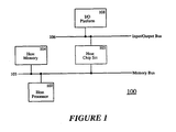
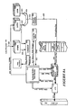
- Figure 1 illustrates a block diagram of a multiple processor computer system implementing the present invention.
Multi-processor system 100 includes ahost processor 102. Thehost processor 102 may include a plurality of processors (i.e., a cluster of tightly coupled processors). Thehost processor 102 is coupled to ahost memory 104 throughhost bus 103. Amemory bus 103 also couples thehost processor 102 andmemory 104 to a host chip set 105. Host chip set 105 includes a memory controller, a cache controller, and a bridge providing the interface between thememory bus 103 and an input/output (I/O) bus 106 (e.g. a PCI bus). - A host chip set 105 is known in the art. For example, when the
host processor 102 is a Pentium™ processor made by Intel, a suitable host chip set 105 is the Trident™ chip set also made by Intel. Similarly, if a P6™ processor is used, then a suitable host chip set 105 is the Orion™ chip set also made by Intel. Thehost processor 102,memory bus 103,host memory 104, and host chip set 105 will be referred to as a host platform in thismulti-processor system 100. - The
multiple processor system 100 further includes an I/O platform 108 that is coupled to thefirst PCI bus 106. Furthermore, I/O platform 108 provides an interface between an address space of afirst PCI bus 106 and an address space of a processor included in the I/O platform 108. I/O platform 108 may also include a bridge that couples thefirst PCI bus 106 to a second PCI bus (not shown). - I/
O platform 108 further provides I/O support for the host processor, and devices (not shown) coupled to thefirst PCI bus 106 and the second PCI bus. Figure 2 illustrates in further detail the I/O platform 200 (previously referred to aselement 108 in Figure 1) that includes the present invention. The I/O platform 200 includes alocal processor 202 coupled tolocal memory 206 via amemory controller 205 through a local bus 204. Thelocal processor 202 may be an Intel 80960 JF processor. - An address translation unit (ATU) 218 is coupled to the local bus 204 and to the first PCI bus 208 (previously refered to as
element 106 in Figure 1). The address translation unit (ATU) 218 translates addresses in the address space of thePCI bus 208 into addresses in theprocessor 202 address space and vice versa. Thus, a transaction on thePCI bus 208 having an address in PCI address space, must be translated into a local bus 204 address space so that thememory controller 205 may access the correct location inlocal memory 206 or theproper register 212 inMU 210. - The
ATU 218 includes an outbound module for translating local bus transactions to PCI bus transactions, an inbound module for translating a PCI bus transaction to a local bus transaction and a control state machine to manage this address translation. With respect to the present invention, theATU 218 can be seen as an address decoder that detects that a particular PCI bus transaction accesses one of theregisters 212 in theMU 210. TheATU 218 after detecting that a transaction is an access to one of the registers in theMU 210, sends a signal throughdata path 221 to initiate thecontrol state machines 214 in theMU 210, which will be described hereinafter. Thecontrol state machines 214 send a plurality of signals throughdata path 221 to theATU 218 to notify theATU 218 that theMU 210 is either not ready to receive the transaction or to instruct theATU 218 to signal a Retry to the requesting process. -
Local bus arbitrator 240 grants control of the local bus 204 to any of the local bus masters (i.e., theMU 210, the inbound module of theATU 218, and the local processor 202). Thearbitration circuit 240 is well known in the art. -
Memory controller 205 is provided for accesses to thelocal memory 206 throughdata paths -
Bus agent 201 may be a host processor or another I/O platform. Moreover,bus agent 201 may include thehost memory 104,host processor 102, the host chip set 105, and thehost bus 103 of Figure 1. In other words,bus agent 201 may itself be a subsystem or any intelligent bus agent. - A messaging unit (MU) 210 is coupled to the local bus 204 and to the
ATU 218. TheMU 210 embodies the teachings of the present invention and includes a plurality ofregisters 212 and a plurality ofstate machines 214. Theseregisters 212 andstate machines 214 will be further described with reference to Figure 3. - Figure 3 illustrates the present invention, as embodied in the
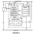
MU 210. TheMU 210 includes a plurality ofstate machines 214 coupled to theATU 218 through control path 350. TheMU 210 also includes a plurality of prefetch andtemporary registers 332. Theseregisters 332 are coupled to theATU 218 throughdata path 336. The prefetch andtemporary registers 332 are also controlled by thecontrol state machine 214 throughdata path 352. Theregisters 332 are also coupled to the local bus 204 throughdata path 334 for accessinglocal memory 206. - In this embodiment, the
MU 210 includes a message passing scheme that uses 4 circular queues. There are four prefetch andtemporary registers 332 in this embodiment. Two registers are provided to allow the host processor to write data to the circular queues. Two registers are provided to allow the host processor to read data from one of the circular queues. - The
MU 210 also includes a plurality of queue pointer registers 340 that are coupled to thecontrol state machines 214 throughdata path 342. Theseregisters 340 store the head and tail pointers of thequeues 207. These queues will be described in greater detail with respect to Figures 4 and 5. - The
MU 210 provides access for thebus agent 201 to fourcircular queues 207. There are two inbound queues and two outbound queues. "Inbound" and "outbound" refer to the direction of the flow of active messages. "Inbound" messages are either new messages posted bybus agent 201 for thelocal processor 202 to process or are empty or free message buffers that are available for use by thebus agents 201. "Outbound" messages are either posted messages by thelocal processor 202 for thehost processor 201 to process or are free message buffers that are available for use by thelocal processor 202. - In one embodiment, there are four circular queues that are used to pass messages between host processor/
bus agent 201 and thelocal processor 202. There are two inbound queues that are used to handle inbound messages, and there are two outbound queues used to handle outbound messages. One of the inbound queues is designated as a Free queue, and it contains inbound free message handles. A message handle is a logical or physical address of a message buffer. The other inbound queue is designated the Post or work queue, and it contains inbound posted message handles. Similarly, one of the outbound queues is designated a Free Queue, and the other outbound queue is designated a Post Queue. - The two outbound queues allow the
local processor 202 to post outbound messages in the Post queue and to receive freed messages returning from anexternal host processor 201 into the outbound Free Queue. The two inbound queues allow thebus agent 201 to acquire a free message buffer from the inbound free queue and subsequently post that buffer to the inbound free queue for processing by thelocal processor 202. - The data storage for the
circular queues 207 are provided bylocal memory 206. In this particular implementation, each entry in the queue is a 32-bit data value which is a message handle. Moreover, a read from or write to a queue may access exactly one queue entry. - Each circular queue has a head pointer and a tail pointer. Writes to a queue occur at the head of the queue and reads occur from the tail. The head and tail pointers are incremented by software running on the
local processor 202 or by themessaging unit 210. The details concerning how the head and tail pointers are incremented by thelocal processor 202 and theMU 210 are described hereinafter. - The head and tail pointers are offsets into each respective circular queue and range from 0 to the circular queue size minus 1 (i.e., begin labeling the pointers with 0). The pointers are incremented after each queue access. Both head and tail pointers wrap around to 0 when they reach the circular queue size (i.e., end of the queue).
- The
Messaging Unit 210 generates an interrupt to thelocal processor 202 or generates a PCI bus interrupt (i.e., interrupt to an external processor) under certain conditions. In general, when a post queue is written, an interrupt is generated to notify the target processor that a message was posted. - In one embodiment the size of each circular queue can range from 16 Kbytes (4096 handles) to 256 Kbytes (65536 handles). Moreover, in this embodiment all four queues are of the same size and are contiguous. The total amount of local memory required by the circular queues thus ranges from 64 Kbytes to 1 Mbytes. These queues reside in
local memory 206, and the head and tail pointers of the queues reside in registers in theMU 210. The queue size is determined by the Queue Size field in the Messaging Unit Configuration Register (MUCR). One possible format of the MUCR is shown in Table 1. In this embodiment there is also one base address for all four queues. The starting addresses of each queue is based on the Queue Base Address and the Queue Size field. The base address is stored in a Queue Base Address Register (QBAR) which also resides in theMU 210. One possible format of the QBAR is shown in Table 2. An embodiment to be illustrated in Figures 6-9 includes a separate base address for each queue.TABLE 1 MU Configuration Register - MUCR Bit Default Read/Write Description 31:05 0000000H Read Only Reserved 04:00 000002 Read/Write Queue Size - This field determines the size of each Circular Queue. All four queues are the same size. TABLE 2 QUEUE BASE ADDRESS REGISTER - QBAR Bit Default Read/Write Description 31:20 000H Read/Write Queue Base Address - Local memory address of the; circular queues. 19:00 00000H Read Only Reserved - Figure 4 illustrates four circular queues of the present invention. There are two
outbound queues inbound queues local memory 206. - The
local processor 202 postsoutbound messages 422 by writing to the head of theoutbound post queue 420. Thehost processor 201 retrieves the posted messages from theoutbound post queue 420 by reading from the tail of theoutbound post queue 420. - A
host processor 201 releases outbound message buffers 412 by writing to the head of the outboundfree queue 410. Thelocal processor 202 reads free messages buffers 414 from the tail of the outboundfree queue 410. - A host processor or
bus agent 201 postsinbound messages 432 to aninbound post queue 430 by writing to the head of theinbound post queue 430. Thelocal processor 202 reads these posted messages from the tail of theinbound post queue 430. When the host processor writes to theinbound post queue 430 an interrupt is generated 436 to thelocal processor 202. - When messages are posted to the
outbound post queue 420 by thelocal processor 202 an interrupt 426 is generated to thehost processor 201. The interrupts as specified by the PCI Bus Specification Revision 2.0 may be used here. - The
local processor 202 returns free message buffers 442 to the inboundfree queue 440 by writing to the head of thisqueue 440. The host processor/bus agent 201 acquires a free message buffer by reading from the tail of the inboundfree queue 440 throughdata path 444. - Figure 5 illustrates an Outbound
Free Queue 510, anOutbound Post Queue 520, anInbound Post Queue 530, and anInbound Free Queue 540. - The Outbound Free Queue (OFQ) 510 holds the handles for empty messages placed there (i.e., released) by
bus agents 201 for thelocal processor 202 to use. Ahost processor 201 releases a message buffer to theOFQ 510 by writing to a register in anOutbound Queue Port 516. TheOFQ 510 is read from the queue tail by thelocal processor 202, and is written to the queue head by thehost processor 201. The head pointer (OFHP) 512 is maintained by theMessaging Unit 210. The Outbound Free Queue tail pointer (OFTP) 514 is maintained by software running on thelocal processor 202. - For a PCI write transaction that accesses the
Outbound Queue Port 516, theMU 210 writes a message handle (i.e., an address to a free message buffer) to a location inlocal memory 206 pointed to by the head pointer (OFHP) 512, which is stored in an Outbound Free Head Pointer Register (OFHPR) 926. The local memory address is the Queue Base Address Register + 3 * Queue Size + Outbound Free Head Pointer Register (OFHPR) 926. One possible format of the OFHPR is shown in Table 3. - When data that is written to the
Outbound Queue Port 516 is written tolocal memory 206, theMU 210 increments theOFHP 512. - From the time that a PCI write transaction is received by the
MU 210 until data is written intolocal memory 206, and theOFHP 512 is incremented, any PCI transaction that attempts to access theInbound Queue Port 516 is delayed by inserting wait states. If a PCI latency violation occurs while inserting wait states, theexternal PCI agent 201 is signaled a Retry. - The
local processor 202 retrieves message buffer handles from theOFQ 510 by reading the local memory location pointed to by the Outbound Free Queue tail pointer (OFTP) 514. The local memory address is Queue Base Address Register + 3 * Queue size + Outbound Free Tail Pointer Register (OFTPR) 438. One possible format of the OFTPR is shown in Table 4. Thelocal processor 202 then increments the OFTP 514 in the Outbound Free Tail Pointer Register 938 (shown in Figure 9A).TABLE 3 Outbound Free Head Pointer Register - OFHPR Bit Default Access Description 31:19 0000H Read Only Reserved 18:02 0000H Read/Write Outbound Free Head Pointer - Local memory offset of the head pointer for the Outbound Post Queue 01:00 002 Read Only Reserved TABLE 4 Outbound Free Tail Pointer Register - OFTPR Bit Default Access Description 31:19 0000H Read Only Reserved 18:02 0000H Read/Write Outbound Free Tail Pointer - Local memory offset of the tail pointer for the Outbound Free Queue 01:00 002 Read Only Reserved - The Outbound Post Queue (OPQ) 520 stores handles of posted messages placed there by the
local processor 202 for thehost processor 201 to retrieve and process. Thehost processor 201 retrieves a message from theOPQ 520 by reading a register in theOutbound Queue Port 516. Thelocal processor 202 adds to theOPQ 520 by writing to the queue head. The head pointer (OPHP) 522 is maintained by thelocal processor 202. The tail pointer (OPTP) 524 is maintained by theMessaging Unit 210. - For a PCI read transaction that accesses the
Outbound Queue Port 516, theMU 210 prefetches the data at the local memory location pointed to by theOPTP 524. The local memory address is Queue Base Address Register + 2 * Queue Size + Outbound Post Tail Pointer Register (OPTPR) 826 (as shown in Figure 8A). If theOPQ 520 is not empty (i.e., thehead 522 andtail pointers 524 are not equal), a message handle is supplied for the requestingprocessor 201. If theOPQ 520 is empty (i.e., thehead 522 andtail pointers 524 are equal), the value of -1 (FFFF.FFFFH) is supplied for the requestingprocessor 201. If theOPQ 520 queue is not empty, and theMU 210 succeeds in prefetching the data at the tail, theMU 210 increments the tail pointer (OPTR) 524 in theOPTPR 826. - As stated, a prefetch mechanism loads a value of -1 (FFFF.FFFFH) into a prefetch register 806 (which will be described further with a reference to Figure 8A) if the
head 522 andtail 524 pointers are equal (i.e., theOPQ 520 is empty). In order to update theORR 806 when messages are added to theOPQ 520, and it becomes non-empty, the prefetch mechanism in theMU 210 automatically starts a prefetch if theORR 806 contains FFFF.FFFFH, and the Outbound Post Head Pointer Register (OPHPR) 422 is written to by the local 202 processor. One possible format of the OPHPR is shown in Table 5. Thelocal processor 202 updates theOPHPR 422 when thelocal processor 202 adds messages to theOPQ 520. - A prefetch must appear atomic from the perspective of an
external bus agent 201. When a prefetch is started, any PCI transaction that attempts to access an Outbound Retrieve Register 806 (which will be described with reference to Figure 8A) in theOutbound Queue Port 516 is delayed by inserting wait states until the prefetch is completed. If a bus latency violation occurs while inserting wait states, theexternal bus agent 201 is notified with a Retry signal. - A PCI interrupt is generated to the
host processor 201 when theOPHP 522 is not equal to theOPTP 524. When theOPHP 522 and theOPTP 524 are equal, no interrupt is generated. The Output Post Queue Interrupt bit in the Outbound Doorbell Register indicates the status of the comparison of the values in theOPHPR 838 andOPTPR 828. The interrupt is cleared when thehead 522 andtail 524 pointers are equal. This occurs when ahost processor 201 reads enough queue entries to empty theOPQ 520. An interrupt may be masked by the Outbound Doorbell Mask Register, which is controlled by software. - The
local processor 202 may place messages in theOPQ 520 by writing data to the local memory location pointed to by the head pointer (OPHP) 522. The local memory address is Queue Base Address Register + Outbound PostHead Pointer Register 838. One possible format of the OPTPR is shown in Table 6. Thelocal processor 202 then increments OPHP 522 in the Outbound PostHead Pointer Register 838.TABLE 5 Outbound Post Head Pointer Register - OPHPR Bit Default Access Description 31:19 0000H Read Only Reserved 18:02 0000H Read/Write Outbound Post Head Pointer - Local memory offset of the head pointer for the Outbound Post Queue 01:00 002 Read Only Reserved TABLE 6 Outbound Post Tail Pointer Register - OPTPR Bit Default Access Description 31:19 0000H Read Only Reserved 18:02 0000H Read/Write Outbound Post Tail Pointer - Local memory offset of the tail pointer for the Outbound Post Queue 01:00 002 Read Only Reserved - The Inbound Post Queue (IPQ) 530 holds handles of posted messages placed there by
bus agents 201 for thelocal processor 202 to process. Thehost processor 201 or bus agent posts a message to theIPQ 530 by writing to a register in theInbound Queue Port 536. TheIPQ 530 is read from the queue tail by thelocal processor 202 and is written to the queue head byexternal bus agents 201. The tail pointer (IPTP) 534 is maintained by software running on thelocal processor 202. The head pointer (IPHP) 532 is maintained by theMU 210. - For a PCI write transaction that accesses the Inbound Queue Port (IQP) 536, the
MU 210 writes the data to a local memory location pointed to by theIPHP 532 stored in Inbound Post Head Pointer Register (IPHPR) 724 (shown in Figure 7A). The local memory address is Queue Base Register + Queue Size + Inbound Post Head Pointer Register (IPHPR) 724. One possible format of the IPHPR is shown in Table 7. One possible format of the IPTPR is shown in Table 8. - When the data written to the
Inbound Queue Port 536 is written tolocal memory 206, theMU 210 increments theIPHPR 724. When data is written tolocal memory 206 and theIPHPR 724 is incremented, theMU 210 generates an interrupt to thelocal processor 202. This interrupt is recorded by setting the Inbound Post Queue Interrupt bit of the Inbound Doorbell Register. The interrupt may be masked by the Inbound Doorbell Mask Register, which is controlled by software.TABLE 7 Inbound Post Head Pointer Register - IPHPR Bit Default Access Description 31:19 0000H Read Only Reserved 18:02 0000H Read/Write Inbound Post Head Pointer - Local memory offset of the head pointer for the Inbound Post Queue 01:00 002 Read Only Reserved TABLE 8 Inbound Post Tail Pointer Register - IPTPR Bit Default Access Description 31:19 0000H Read Only Reserved 18:02 0000H Read/Write Inbound Post Tail Pointer - Local memory offset of the tail pointer for the Inbound Post Queue 01:00 002 Read Only Reserved - An
Inbound Free Queue 540 holds handles of empty message buffers placed there by thelocal processor 202 forbus agents 201 to use. Thehost processor 201 is allocated a message buffer from theIFQ 540 by reading a register in theInbound Queue Port 536. TheInbound Free Queue 540 is read from the queue tail byexternal bus agents 201 and is written to the queue head by thelocal processor 202. Thehead pointer 542 is maintained by software running on thelocal processor 202. The tail pointer (IFTP) 544 is maintained by theMU 210. - For a PCI read transaction that accesses the Inbound Queue Port (IQP) 536, the
MU 210 prefetches the data at a local memory location pointed by theIFTP 544. The local memory address is Queue Base Address Register + Inbound Free Tail Pointer Register (IFTPR) 626 that stores the tail pointer. One possible format of the IFTPR is shown in Table 10. If theIFQ 540 is not empty (i.e., head and tail pointers are not equal), the data pointed to byIFTP 544 is supplied for the next access by the host processor or bus agent. If theIFQ 540 is empty (i.e., head and tail pointers are equal), the value of -1 (FFFF.FFFFH) is supplied for the requesting host processor or bus agent. If theIFQ 540 was not empty, and theMU 210 prefetches the data pointed to by theIFTP 544, theMU 210 increments the value of the pointer in the Inbound Free Tail Pointer Register (IFTPR) 626 (as shown in Figure 6A). - To reduce latency for the PCI read access, the
MU 210 implements a prefetch mechanism to anticipate accesses to theIFQ 540. TheMU 210 prefetches data from the tail of theIFQ 540 and loads it into an internal prefetch register. When a PCI read access occurs, the data can be read directly from the prefetch register. - The prefetch mechanism loads a value of -1 (FFFF.FFFFH) into the prefetch register if the head and tail pointers are equal (i.e.,
IFQ 540 is empty). In order to update the prefetch register when messages are added to theIFQ 540 and it becomes non-empty, the prefetch mechanism automatically starts a prefetch if the prefetch register contains FFFF.FFFFH, and the Inbound Free Head Pointer Register (IFHPR) 638 is written. One possible format of the IFHPR is shown in Table 9. The software running on thelocal processor 202 updates theIFHP 542 when it adds messages to theIFQ 540. - A prefetch must appear atomic from the perspective of an
external bus agent 201. When a prefetch is started, any PCI transaction that attempts to access the Inbound Free Register in theInbound Queue Port 536 is delayed by inserting wait states until the prefetch is completed. If a PCI latency violation occurs while inserting wait states, theexternal bus agent 201 is signaled a Retry by theMU 210. - The
local processor 202 may place messages in theIFQ 540 by writing the data to the local memory location pointed to by the head pointer (IFHP) 542. The local memory address is Queue Base Address Register + Inbound Free Head Pointer Register (IFHPR) 638. The software running on thelocal processor 202 then increments theIFHPR 638.
Inbound Free TableTABLE 9 Inbound Free Head Pointer Register - IFHPR Bit Default Access Description 31:19 0000H Read Only Reserved 18:02 0000H Read/Write Inbound Free Head Pointer - Local memory offset of the head pointer for the Inbound Free Queue. 01:00 002 Read Only Reserved TABLE 10 Inbound Free Tail Pointer Register - IFTPR Bit Default Access Description 31:19 0000H Read Only Reserved 18:02 0000H Read/Write Inbound Free Tail Pointer - Local memory offset of the tail pointer for the Inbound Free Queue. 01:00 002 Read Only Reserved - Figure 6A illustrates how the present invention, embodied in the
MU 210, allocates free message buffers to bus agents on the PCI bus. Data moves from an Inbound Free Queue (IFQ) 540 located inlocal memory 206 through local data bus to an Inbound Free Register (IFR) 606. In this context data specifically refers to an address of a message buffer (i.e., message handle). Subsequently, the data travels from theInbound Free Register 606 throughdata path 608 toATU 218, and thereafter to bus agents onPCI bus 208 throughdata path 610. - The
MU 210 includes an InboundFree state machine 612 for allocating free message buffers that issues and receives a number of control signals. The state diagram for the InboundFree state machine 612 will be further described with reference to Figure 6B. - To request a message buffer from
IFQ 540, a bus agent sends a read transaction through thePCI bus 208 anddata path 610 to theATU 218. A read transaction specifying the address of theInbound Free Register 606 is detected by theATU 218. Once theATU 218 detects that a bus agent wants to read theInbound Free Register 606, the ATU tests the state of the IFR_Ready signal 614. If an IFR_Ready signal 614 is asserted the ATU completes the PCI transaction supplying the data in theIFR 606 to theATU 218 throughpath 608 and generates aRead_Inbound_Free signal 616 tostate machine 612. - If the IFR_Ready signal 614 is de-asserted (i.e.,
state machine 612 is not ready), theATU 218 inserts wait states, and does not send theRead_IFR 616 until the IFR_Ready signal 614 is asserted. The IFR_Ready signal 614 is de-asserted when there is stale data in the IFR 606 (i.e.,state machine 612 has not yet completed a Prefetch of data into IFR 606). - Once
state machine 612 receives theRead_IFR signal 616,state machine 612 sends aMemory_Read_Request signal 618 to alocal bus arbitrator 240 and de-asserts the IFR_Ready signal 614. Upon aGrant signal 632, theMU 210 simply asserts the proper tail address of theIFQ 540 onto thelocal address bus 630. Data is then transferred from thelocal memory 206 to the IFR 606 (i.e., reads the value at the tail of theIFQ 540 through thelocal data bus 604.MU 210 includes anadder 624 that calculates the appropriate tail address of theIFQ 540.Adder 624 generates the sum of the contents of the Inbound Free Tail Pointer Register (IFTPR) 626 and the Inbound Free Base Register (IFBR) 628. - After the data pointed to by the tail pointer of the
IFQ 540 is on thelocal data bus 604,state machine 612 sends a Latch signal 634 to latch the data on thelocal data bus 604 into theIFR 606 and sends anIncrement signal 644 to theIFTPR 626. Thus, a prefetch of the next available message buffer has been accomplished. - The
MU 210 also includes acomparator 636 that compares the value in the Inbound Free Head Pointer Register (IFHPR) 638 and the value in the Inbound Free Tail Pointer Register (IFTPR) 626. If these two values are equal,comparator 636 generates an Empty signal 640 (i.e., there are no free message buffers in the queue). ThisEmpty signal 640 is sent tostate machine 612 and causesstate machine 612 to assert aPreset signal 642. ThePreset signal 642 causes the content ofIFR 606 to be set to a predetermined value that is reserved for an empty indication (i.e., not a valid buffer address). - When a bus agent reads the
IFR 606, it either immediately accesses prefetched data stored in theIFR 606, or the Preset value, that indicates that the IFQ 602 is Empty. - Figure 6B illustrates the state diagram for Inbound
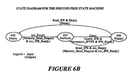
Free state machine 612.State machine 612 has three stages: Empty 650, aPrefetch 652 and Primed 656.State machine 612 is in theEmpty state 650 until the Empty signal is de-asserted 654. A not_Empty signal transitions thestate machine 650 from anEmpty state 612 toPrefetch state 652, and thestate machine 612 issues aMemory_Read_Request signal 618 and de-asserts the IFR_Ready signal 614. - The
state machine 612 transitions from thePrefetch state 652 to a Primedstate 656 upon aGrant signal 632. Upon receiving aGrant signal 632,state machine 612 outputs a Latch_IFR signal 634, anIncrement_IFTPR signal 644, and asserts an IFR_Ready signal 614. Thestate machine 612 transitions from the Primedstate 656 to thePrefetch state 652 when theRead_IFR signal 616 is received, and the Empty signal 654 is not asserted. This transition also generates aMemory_Read_Request signal 618 and de-asserts the IFR_Ready signal 614. - The
state machine 612 transitions from the Primedstate 656 to theEmpty state 650 when theRead_IFR signal 616 is received, and theEmpty signal 640 is asserted. This transition generates thePreset signal 642. - Figure 7A illustrates how the present invention posts a message, generated by a bus agent, into the Inbound Post Queue (IPQ) 530 which is located in
local memory 206. - When a bus agent wants to write to an Inbound Post Register (IPR) 706, the data travels from the
PCI bus 208 throughdata path 702 to theATU 218, and then to theIPR 706 throughdata path 704. After the data is latched into theIPR 706, it is transferred throughlocal data bus 604 into theIPQ 530 inlocal memory 206. - The
ATU 218 tests the state of an IPR_Ready signal 716. If the IPR_Ready signal 716 is asserted, theATU 218 completes the PCI transaction by supplying data to theIPR 706 and generating aWrite_IPR signal 718 to thestate machine 712. - If the IPR_Ready signal 716 is not asserted, the
ATU 218 inserts wait states, and completes the PCI transaction when the IPR_Ready signal 716 is asserted. The requesting process retains control of the bus, and the PCI transaction is completed unless PCI latency rules are violated. - The
ATU 218 also tests the state of an IPR_Retry signal 714. If the IPR_Retry signal 714 is asserted, the PCI transaction is not completed, and a retry is signaled to requesting process so it will release the bus and try again at a later time. - The Inbound
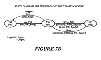
Post state machine 712 of theMU 210 is further illustrated by a state diagram illustrated in Figure 7B.State machine 712 has three states: anIdle state 750, aPost state 752 and aFull state 754.State machine 752 will transition from anIdle state 750 to aPost state 752 when aWrite_Inbound_Post signal 718 is asserted by theATU 218. When the Write_Inbound_Post signal is received by thestate machine 712, thestate machine 712 generates aMemory_Write_Request signal 720 and de-asserts the IPR_Ready signal 716. Thestate machine 712 transitions from aPost state 752 back to theIdle state 750 when thestate machine 712 receives a Grant signal 728 from thelocal bus arbitrator 240. Upon receiving aGrant signal 728 and writingIPR data 604 to memory, thestate machine 712 generates anIncrement signal 740 to the Inbound Post Head Pointer Register (IPHPR) 724, and also asserts the IPR_Ready signal 716. - The
state machine 712 transitions from anIdle state 750 to aFull state 754 when it receives aFull signal 738 from thecomparator 734. AFull signal 738 is generated by thecomparator 734 when the contents of the Inbound Post Tail Pointer Register (IPTPR) 730 and the Inbound Post Head Pointer Register (IPHPR) 724 indicate that the Inbound Post Queue (IPQ) 530 is Full. Upon receiving aFull signal 738,state machine 712 asserts a IPR_Retry signal 714 to theATU 218. -
State machine 712 transitions from aFull state 754 to anIdle state 750 when the Full signal 756 is de-asserted Full signal 756 (i.e., not_Full). Upon receiving a not_Full signal, thestate machine 712 de-asserts the IPR_Retry signal 714. -
Comparator 734 also generates anot_Empty signal 736 to interrupt generation logic (not shown) that generates a local interrupt to the I/O processor. Logic to generate a local interrupt upon receiving anot_Empty signal 736 is known in the art. This logic may also include interrupt registers and also mask registers controlled by software, to selectively mask out interrupts. -
Increment signal 740 is sent to theIPHPR 724 and increments the Inbound Post Head Pointer. Theadder 722 calculates a newinbound head pointer 723 by using thevalue 725 of theIPHPR 724 and thevalue 727 ofIPBR 726. Thisaddress 723 is sent tomemory controller 205 to access local memory through the local bus (i.e., local address bus 630). - As explained previously, the
MU 210 asserts theaddress 723 on thelocal address bus 630 and enables the transfer of data (i.e., address of a message buffer) that is latched in theIPR 706 into the head of theIPQ 530. - Figure 8A illustrates the Outbound Retrieve
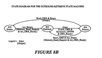
State Machine 812 and how the present invention allows a host processor or bus agent to retrieve posted messages from the Outbound Post Queue 520 (OPQ). When a host processor or bus agent retrieves a posted message handle, the data (i.e., the address of the Message Buffer) travels from theOPQ 520 located inlocal memory 206 to an outbound retrieve register (ORR) 806 throughlocal data bus 604. The data is then passed from theORR 806 throughdata path 808 to the outbound portion of theATU 218. The data is then passed throughdata path 810 throughPCI bus 208 to the respective host processor or bus agent.State machine 812de-asserts ORR_Ready 814 to indicate stale data inORR 806. When ORR_Ready signal 814 is de-asserted, theATU 218 will insert wait states until theORR_Ready signal 814 is asserted, which indicates that theORR 806 contains valid data. - The Outbound Retrieve
state machine 812 of theMU 210 is further illustrated by a state diagram shown in Figure 8B. The Outbound Retrievestate machine 812 has three states: Empty 850,Prefetch 852, and Primed 856. The Outbound Retrieve state machine transitions from theEmpty state 850 to thePrefetch state 852 when theEmpty signal 840 is de-asserted. In response, the Outbound Retrievestate machine 812 asserts aMemory_Read_Request 818 to the localbus arbitration unit 240 and de-asserts theORR_Ready signal 814 while it waits for aGrant signal 832. While waiting for the Grant signal 832, theAdder 824 calculates the address of the next message (i.e., tail pointer), and places this address on thelocal address bus 630. -
State machine 812 transitions from aPrefetch 852 to a Primedstate 856 uponGrant signal 832. Thememory controller 205 uses theaddress 825 and reads the appropriate message handle from theOPQ 520. This message handle (i.e., pointer) is placed on thelocal data bus 604 and transferred to theORR 806. Thestate machine 812 then generates aLatch_ORR 834 to latch the data from theOPQ 520 into theORR 806 and also generates theIncrement_OFTPR signal 844 to increment the tail pointer ofOPQ 520 which is stored in theOPTPR 826. After this prefetch is completed, and new data is latched intoORR 806,state machine 812 asserts aORR_Ready signal 814 to notify theATU 218 that it is ready to complete another transaction from thePCI bus 208. - The
state machine 812 transitions from a Primedstate 856 to aPrefetch state 852 when theRead_ORR signal 816 is generated, and theEmpty signal 840 is de-asserted. In response, thestate machine 812 asserts theMemory_Read_Request signal 818 to thelocal bus arbitrator 240 and de-asserts theORR_ready signal 814 to theATU 218, so that a later transaction will not read the contents of theORR 806 until a prefetch has been completed. -
State machine 812 transitions from a Primedstate 856 to anEmpty state 850 upon detecting a Read_ORR signal that is asserted when anempty signal 840 is asserted. In response,state machine 812 asserts aPreset signal 842. ThePreset signal 842 causes the content of theORR 806 to be set to a value that is reserved for an empty indication so that a transaction requesting a read from theOPQ 520 will be notified that theOPQ 520 is empty. - When
comparator 836 compares the contents ofOPHPR 838 andOPTPR 826, and the values are equal, theEmpty signal 840 is asserted. A non_empty OPQ 520 (i.e., not_Empty) indicates that there are messages pending for processing by thehost processor 201. The present invention includes logic (not shown) to generate an interrupt to thehost processor 201 through the interrupt lines specified in the PCI Bus Specification Release 2.0. - Figures 9A and 9B illustrate the Outbound
Release state machine 912. After ahost processor 201 processes a message, it returns the free message buffer pointer via thePCI bus 208 throughdata path 904 to theATU 218 and is latched in an Outbound Release Register (ORLSR) 906. The free message buffer handle is then sent to the Outbound Free Queue (OFQ) 510 from the Outbound Release Register (ORLSR) 906 throughlocal data bus 604. To release a free message buffer, ahost processor 201 simply writes the address of that free message buffer to theORLSR 906 in one bus transaction cycle. - The
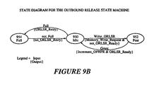
ATU 218 tests the state of anORLSR_Ready signal 916 and anORLSR_Retry signal 914. If theORLSR_Retry signal 914 is de-asserted, the PCI transaction (i.e., write to the ORLSR 906) is not completed. The requesting process is signaled a Retry, and the requesting process releases control of the bus and tries again at a later time. If theORLSR_Ready signal 916 is de-asserted, theATU 218 inserts wait states until theORLSR_Ready signal 916 is asserted. When theORLSR_Ready signal 916 is asserted, theATU 218 generates theWrite_ORLSR signal 918 to thestate machine 912 and latches data into theORLSR 906. - Figure 9B illustrates a state diagram for the Outbound
Release state machine 912.State machine 912 has three states: aFull state 954, anIdle state 950 and aPost state 952. Thestate machine 912 transitions from anIdle state 950 to aFull state 954 when aFull signal 940 is asserted bycomparator 936. In response to thisFull signal 940,state machine 912 asserts aORLSR_Retry signal 914 to theATU 218. Upon generation of aORLSR_Retry signal 914, the process that initiates a write transaction to theORLSR 906 is signaled to try again at a later time. - The
state machine 912 transitions from aFull state 954 to anIdle state 950 when theFull signal 940 is de-asserted. If the OutboundFree Queue OFQ 510 is not full, thenstate machine 912 de-asserts the ORLSR_Retry signal 914 (i.e., there is room in theOFQ 510 for an additional free message handle). -
State machine 912 transitions from anIdle state 950 to aPost state 952 when it receives aWrite_ORLSR signal 918 from theATU 218. TheWrite_ORLSR signal 918 also serves to latch the free message handle into theORLSR 906. In response to theWrite_ORLSR signal 918 being asserted,state machine 912 asserts aMemory_Write_Request signal 918 to thelocal bus arbiter 240 and waits for a Grant signal 932 from the arbiter. AnAdder 925 calculates the next position in theOFQ 510 where the next free message handle is to be written.State machine 912 also de-asserts theORLSR_Ready signal 916 to prevent a subsequent transaction from overriding the data that is now latched in theORLSR 906. - The
state machine 912 transitions from aPost state 952 to anIdle state 950 when it receives a Grant signal 932 from thelocal bus arbiter 240. In response, the OutboundRelease state machine 912 increments the head pointer in theOFHPR 926 through anIncrement_OFHPR signal 944.State machine 912 also asserts theORLSR_Ready signal 916, indicating to theATU 218 that it has already stored the contents of theORLSR 906, and that it has calculated the OFQ address to which the next free message handle is to be stored, and is ready for the next write to theORLSR 906. - In summary, a host processor releases a free message buffer to the
OFQ 510 by writing its handle to theORLSR 906. If theOFQ 510 is full, the requesting process is notified to retry later. If theOFQ 510 is not full, the handle of the free message buffer is latched into theORLSR 906.State machine 912 then waits for a Grant signal 932 from thelocal bus arbiter 240 to gain access to the local bus. Once control of the local bus is granted,state machine 912 transfers the data latched in theORLSR 906 to theOFQ 510 at the location pointed to by the pre-calculated head pointer/address. - Thus, a method and apparatus that enables a remote process to allocate a message buffer then posts that message buffer to a work queue without the use of a semaphore or locking of the bus has been described.
- Furthermore, a method and apparatus for retrieving a message from a work queue and releasing the message to a free queue after the message has been processed by a host processor, has been described.
- The present invention also provides for scalability, flexibility, and compatibility with other platforms. For example, all platforms including an inbound message queue, as previously described, can easily send interprocessor messages. For compatibility with other platforms that do not implement an inbound message queue an outbound message queue supplies that platform with an equivalent functionality without modifying the hardware of the platform. Moreover, the present invention allows for abstraction in that other platforms may use one platform's inbound queue concurrently without express knowledge that other processors exist in the computer system.
- Thus, the present invention provides a method and apparatus for directly passing messages in a highly efficient manner between processors without requiring hardware modification to the processors in an asymmetric multi-processor system.
Claims (12)
- A messaging unit (210) coupled to a local processor (202) and memory (206) through a local bus (204), and further coupled to a host processor (201) through a second bus (208), said messaging unit (210) comprising:a) an inbound free storage means (540) defined by tail and head pointers for storing handles of empty message buffers, placed therein by said local processor (202), for use by bus agents external to said messaging unit, the head pointer (638) being maintained by said local processor; andb) an inbound free circuitry means (612) coupled to the inbound free storage means (540) maintaining the tail pointer (544) and for operating on data in an inbound free register means (606) wherein the operation on data by the inbound free circuitry means (612) further includes prefetching information into said inbound register means (606) from the inbound free storage means stored in the memory, as indicated by the tail pointer, if the inbound free storage means is not empty, and incrementing the tail pointer, and if the inbound free storage means is empty loading the inbound free register means with a predetermined value, and allowing the host processor to read the inbound free register means in one transaction if the prefetch operation is completed.
- The messaging unit as set forth in claim 1 further comprisinga) an outbound post storage means for storing handles of posted messages, placed therein by said local processor, for processing by said host processor;b) an outbound post circuitry means coupled to the outbound post storage means for operating on data in an outbound post register means;c) an outbound free storage means for storing handles of empty messages, placed therein by bus agents external to said messaging unit, for use by said local processor; andd) an outbound free circuitry means coupled to the outbound free storage means for operating on data in an outbound free register means.
- The messaging unit as set forth in claim 1 further comprising:a) an inbound post storage means for storing handles of posted messages, placed therein by bus agents external to said messaging unit, for processing by said local processor; andb) an inbound post circuitry means coupled to inbound post storage means for operating on data in an inbound post register means wherein the operation on data by the inbound post circuitry means further includes detecting if the inbound post storage means is full, returning a retry signal to the host processor if the inbound post storage means is full, and allowing the host processor to write the inbound post register means if the inbound post storage means is not full and the current value stored in the inbound post register means has been stored into the inbound post storage means.
- The messaging unit as set forth in claim 2
wherein the operation on data by the outbound post circuitry means further includes prefetching data from the outbound post storage means if the outbound post storage means is not empty, loading the outbound post register means with a predetermined value if the outbound post storage means is empty, and allowing the host processor to read the outbound post register means if the prefetch is completed; and
wherein the operation on data by the outbound free circuitry means further includes detecting if the outbound free storage means is full, returning a retry signal to the host processor if the outbound free storage means is full, and allowing the host processor to write the outbound free register means if the outbound free storage means is not full and the current value in the outbound free register means has been stored into the outbound free storage means. - The messaging unit as set forth in claim 2 wherein the second bus is a PCI bus.
- The messaging unit as set forth in claim 2 wherein each of the storage means is accessed by an external bus agent such as the host processor, using a bus transaction on the second bus.
- A method implemented in a system having a messaging unit (210) coupled to a local processor (202) and memory (206) through a local bus (204) and further coupled to a host processor (201) through a second bus (208), the method for enabling the host processor (201) at least
to retrieve a message handle from an outbound post queue (520) in the memory (206), said outbound post queue (520) storing message handles placed there by the local processor (202)
or to be allocated free message buffers from an inbound free queue (540) in the memory (206), said inbound free queue (540) storing handles of free message buffers placed there by said local processor (202)
by reading a prefetch register (806,606) of the messaging unit (210), in one bus transaction, wherein a queue of said outbound post queue or said inbound free queue being defined by a tail pointer (626,826) maintained in the messaging unit (210) and a head pointer (638,838) maintained by the local processor (202),
said method further comprising the steps of:detecting whether or not the queue is empty;if the queue is empty, then storing a preset value in the prefetch register (806,606) to indicate to the host processor (201) the queue is empty;if the queue is not empty, then prefetching the next message handle from the queue as pointed to by the tail pointer (626,826),reading data from said queue as indicated by said tail pointer (626,826) and latching the data into the prefetch register (806,606) and incrementing the tail pointer (626,826) of the queue, andindicating (614,814) that said prefetch register (806,606) contains valid data once the prefetching is complete, to return content of the prefetch register (806,606) to the host processor (201). - The method as set forth in claim 7 wherein the host processor retrieves the message handle, said message handle having been posted by the local processor to the queue being an outbound post queue.
- The method as set forth in claim 7 wherein the host processor allocates the message handle from the queue being an inbound free queue.
- A method implemented in a system having a messaging unit (210) coupled to a local processor (202) and memory (206) through a local bus (204) and further coupled to a host processor (201) through a second bus (208), the method for enabling the host processor (201) at least
to release a message handle into an outbound free queue (510) in the memory (206), said outbound post queue (510) storing handles for empty message placed there by the host processor (201) for the local processor (202)
or to post a message handle into an inbound post queue (530) in the memory (206), said inbound post queue (530) storing handles of posted messages placed there by said host processor (201) for the local processor (202) by writing a register (706,906) of the messaging unit (210), in one bus transaction, wherein a queue of said outbound free queue or said inbound post queue being defined by a tail pointer (730,938) maintained in the local processor (202) and a head pointer (724,926) maintained by messaging unit (210),
said method further comprising the steps of:detecting whether or not the queue is full;if the queue is not full, latching the message handle in said register (706,906); writing the handle in the register to the queue at a location pointed to by the head pointer (730,936); and incrementing the head pointer (724,926); andif the queue is full, signalling the host processor (201) to retry at a later time. - The method of claim 10 wherein the host processor releases the message handle being a free message handle, to the queue being a free queue.
- The method of claim 10 wherein the host processor posts the message handle to the queue being an inbound post queue.
Applications Claiming Priority (3)
| Application Number | Priority Date | Filing Date | Title |
|---|---|---|---|
| US08/490,651 US5925099A (en) | 1995-06-15 | 1995-06-15 | Method and apparatus for transporting messages between processors in a multiple processor system |
| US490651 | 1995-06-15 | ||
| PCT/US1996/010466 WO1997000533A1 (en) | 1995-06-15 | 1996-06-17 | A method and apparatus for transporting messages between processors in a multiple processor system |
Publications (3)
| Publication Number | Publication Date |
|---|---|
| EP0840935A1 EP0840935A1 (en) | 1998-05-13 |
| EP0840935A4 EP0840935A4 (en) | 1998-12-23 |
| EP0840935B1 true EP0840935B1 (en) | 2006-12-20 |
Family
ID=23948942
Family Applications (1)
| Application Number | Title | Priority Date | Filing Date |
|---|---|---|---|
| EP96919466A Expired - Lifetime EP0840935B1 (en) | 1995-06-15 | 1996-06-17 | A method and apparatus for transporting messages between processors in a multiple processor system |
Country Status (9)
| Country | Link |
|---|---|
| US (2) | US5925099A (en) |
| EP (1) | EP0840935B1 (en) |
| JP (1) | JP3884073B2 (en) |
| KR (1) | KR19990022951A (en) |
| CN (1) | CN1099078C (en) |
| AU (1) | AU6180196A (en) |
| DE (1) | DE69636781D1 (en) |
| HK (1) | HK1010940A1 (en) |
| WO (1) | WO1997000533A1 (en) |
Families Citing this family (85)
| Publication number | Priority date | Publication date | Assignee | Title |
|---|---|---|---|---|
| US5925099A (en) * | 1995-06-15 | 1999-07-20 | Intel Corporation | Method and apparatus for transporting messages between processors in a multiple processor system |
| US5987590A (en) * | 1996-04-02 | 1999-11-16 | Texas Instruments Incorporated | PC circuits, systems and methods |
| US6179489B1 (en) | 1997-04-04 | 2001-01-30 | Texas Instruments Incorporated | Devices, methods, systems and software products for coordination of computer main microprocessor and second microprocessor coupled thereto |
| US5966547A (en) * | 1997-01-10 | 1999-10-12 | Lsi Logic Corporation | System for fast posting to shared queues in multi-processor environments utilizing interrupt state checking |
| EP1018074A4 (en) * | 1997-03-13 | 2002-02-06 | Mark M Whitney | A system for, and method of, off-loading network transactions from a mainframe to an intelligent input/output device, including off-loading message queuing facilities |
| US6477584B1 (en) * | 1997-03-21 | 2002-11-05 | Lsi Logic Corporation | Message FIFO empty early warning method |
| US6105119A (en) * | 1997-04-04 | 2000-08-15 | Texas Instruments Incorporated | Data transfer circuitry, DSP wrapper circuitry and improved processor devices, methods and systems |
| US5909559A (en) * | 1997-04-04 | 1999-06-01 | Texas Instruments Incorporated | Bus bridge device including data bus of first width for a first processor, memory controller, arbiter circuit and second processor having a different second data width |
| JPH10307751A (en) * | 1997-05-09 | 1998-11-17 | Hitachi Ltd | Data transfer device by pointer control for parallel computer |
| JPH11127148A (en) * | 1997-10-20 | 1999-05-11 | Fujitsu Ltd | Recovery processing unit and method for registration information in stored exchange type electronic conference system and medium recorded with recovery processing program |
| US6145007A (en) * | 1997-11-14 | 2000-11-07 | Cirrus Logic, Inc. | Interprocessor communication circuitry and methods |
| US6145061A (en) * | 1998-01-07 | 2000-11-07 | Tandem Computers Incorporated | Method of management of a circular queue for asynchronous access |
| US7007126B2 (en) * | 1998-02-13 | 2006-02-28 | Intel Corporation | Accessing a primary bus messaging unit from a secondary bus through a PCI bridge |
| US6124868A (en) * | 1998-03-24 | 2000-09-26 | Ati Technologies, Inc. | Method and apparatus for multiple co-processor utilization of a ring buffer |
| US5990910A (en) * | 1998-03-24 | 1999-11-23 | Ati Technologies, Inc. | Method and apparatus for co-processing multi-formatted data |
| JP4236729B2 (en) * | 1998-05-07 | 2009-03-11 | 株式会社リコー | Data processing device |
| US6314501B1 (en) * | 1998-07-23 | 2001-11-06 | Unisys Corporation | Computer system and method for operating multiple operating systems in different partitions of the computer system and for allowing the different partitions to communicate with one another through shared memory |
| US6173307B1 (en) * | 1998-08-20 | 2001-01-09 | Intel Corporation | Multiple-reader multiple-writer queue for a computer system |
| US7020712B1 (en) * | 1998-09-30 | 2006-03-28 | Cisco Technology, Inc. | Reducing CPU overhead in the forwarding process in an inbound/outbound controller for a router |
| US6182182B1 (en) * | 1998-10-28 | 2001-01-30 | Adaptec, Inc. | Intelligent input/output target device communication and exception handling |
| US6212543B1 (en) | 1998-12-10 | 2001-04-03 | Intel Corporation | Asymmetric write-only message queuing architecture |
| US6256699B1 (en) * | 1998-12-15 | 2001-07-03 | Cisco Technology, Inc. | Reliable interrupt reception over buffered bus |
| US6209054B1 (en) | 1998-12-15 | 2001-03-27 | Cisco Technology, Inc. | Reliable interrupt reception over buffered bus |
| US6381663B1 (en) * | 1999-03-26 | 2002-04-30 | Hewlett-Packard Company | Mechanism for implementing bus locking with a mixed architecture |
| NO312926B1 (en) * | 1999-07-20 | 2002-07-15 | Ericsson Telefon Ab L M | Communication over multimaster bus |
| US6976260B1 (en) * | 1999-09-24 | 2005-12-13 | International Business Machines Corporation | Method and apparatus for serializing a message queue in a multiprocessing environment |
| US6772097B1 (en) * | 1999-09-30 | 2004-08-03 | Intel Corporation | Retrieving I/O processor performance monitor data |
| US6918044B1 (en) | 1999-10-15 | 2005-07-12 | Cisco Technology, Inc. | Password protection for high reliability computer systems |
| US6467049B1 (en) | 1999-10-15 | 2002-10-15 | Cisco Technology, Inc. | Method and apparatus for configuration in multi processing engine computer systems |
| US6484224B1 (en) | 1999-11-29 | 2002-11-19 | Cisco Technology Inc. | Multi-interface symmetric multiprocessor |
| US6609171B1 (en) * | 1999-12-29 | 2003-08-19 | Intel Corporation | Quad pumped bus architecture and protocol |
| US6611882B1 (en) * | 1999-12-31 | 2003-08-26 | Intel Corporation | Inbound and outbound message passing between a host processor and I/O processor local memory |
| GB2368247A (en) * | 2000-10-18 | 2002-04-24 | Power X Ltd | Method and apparatus for regulating process state control messages |
| US6988160B2 (en) * | 2001-02-12 | 2006-01-17 | P-Cube Ltd. | Method and apparatus for efficient messaging between memories across a PCI bus |
| US6836480B2 (en) * | 2001-04-20 | 2004-12-28 | International Business Machines Corporation | Data structures for efficient processing of multicast transmissions |
| US6799217B2 (en) * | 2001-06-04 | 2004-09-28 | Fujitsu Limited | Shared memory multiprocessor expansion port for multi-node systems |
| US6760817B2 (en) * | 2001-06-21 | 2004-07-06 | International Business Machines Corporation | Method and system for prefetching utilizing memory initiated prefetch write operations |
| US7089555B2 (en) | 2001-06-27 | 2006-08-08 | International Business Machines Corporation | Ordered semaphore management subsystem |
| US7454753B2 (en) * | 2001-06-27 | 2008-11-18 | International Business Machines Corporation | Semaphore management subsystem for use with multi-thread processor systems |
| US6801976B2 (en) | 2001-08-27 | 2004-10-05 | Intel Corporation | Mechanism for preserving producer-consumer ordering across an unordered interface |
| US7406690B2 (en) * | 2001-09-26 | 2008-07-29 | International Business Machines Corporation | Flow lookahead in an ordered semaphore management subsystem |
| US7143414B2 (en) | 2001-09-26 | 2006-11-28 | International Business Machines Corporation | Method and apparatus for locking multiple semaphores |
| US7054925B2 (en) * | 2001-11-21 | 2006-05-30 | International Business Machines Corporation | Efficient method for determining record based I/O on top of streaming protocols |
| US20030110232A1 (en) * | 2001-12-11 | 2003-06-12 | International Business Machines Corporation | Distributing messages between local queues representative of a common shared queue |
| US7290127B2 (en) * | 2001-12-26 | 2007-10-30 | Intel Corporation | System and method of remotely initializing a local processor |
| US6813658B2 (en) * | 2002-03-27 | 2004-11-02 | Intel Corporation | Dynamic data queuing mechanism for packet networks |
| US7899924B2 (en) * | 2002-04-19 | 2011-03-01 | Oesterreicher Richard T | Flexible streaming hardware |
| US20040006635A1 (en) * | 2002-04-19 | 2004-01-08 | Oesterreicher Richard T. | Hybrid streaming platform |
| US20040006636A1 (en) * | 2002-04-19 | 2004-01-08 | Oesterreicher Richard T. | Optimized digital media delivery engine |
| US20040107240A1 (en) * | 2002-12-02 | 2004-06-03 | Globespan Virata Incorporated | Method and system for intertask messaging between multiple processors |
| US7013355B2 (en) * | 2003-01-09 | 2006-03-14 | Micrel, Incorporated | Device and method for improved serial bus transaction using incremental address decode |
| DE102004012516A1 (en) * | 2004-03-15 | 2005-10-13 | Infineon Technologies Ag | Computer system for electronic data processing |
| JP4729570B2 (en) * | 2004-07-23 | 2011-07-20 | ビーチ・アンリミテッド・エルエルシー | Trick mode and speed transition |
| US20070276973A1 (en) * | 2004-09-30 | 2007-11-29 | Intel Corporation | Managing queues |
| US8117620B2 (en) * | 2005-03-21 | 2012-02-14 | Intel Corporation | Techniques for implementing a communication channel with local and global resources |
| EP1715405A1 (en) * | 2005-04-19 | 2006-10-25 | STMicroelectronics S.r.l. | Processing method, system and computer program product for dynamic allocation of processing tasks in a multiprocessor cluster platforms with power adjustment |
| US7949863B2 (en) * | 2006-03-30 | 2011-05-24 | Silicon Image, Inc. | Inter-port communication in a multi-port memory device |
| CN100538690C (en) * | 2006-04-10 | 2009-09-09 | 中国科学院研究生院 | The method that message is transmitted between a kind of multi-CPU system and the CPU |
| US9274859B2 (en) * | 2006-05-25 | 2016-03-01 | Nvidia Corporation | Multi processor and multi thread safe message queue with hardware assistance |
| US7913055B2 (en) * | 2006-11-04 | 2011-03-22 | Virident Systems Inc. | Seamless application access to hybrid main memory |
| US20090248919A1 (en) * | 2008-03-25 | 2009-10-01 | Jerzy Szwagrzyk | Method for external fifo acceleration |
| US8566930B2 (en) * | 2009-02-27 | 2013-10-22 | Science Applications International Corporation | Monitoring module |
| US20100262979A1 (en) * | 2009-04-08 | 2010-10-14 | Google Inc. | Circular command queues for communication between a host and a data storage device |
| US8745291B2 (en) * | 2011-10-04 | 2014-06-03 | Qualcomm Incorporated | Inter-processor communication apparatus and method |
| WO2013100783A1 (en) | 2011-12-29 | 2013-07-04 | Intel Corporation | Method and system for control signalling in a data path module |
| US10331583B2 (en) | 2013-09-26 | 2019-06-25 | Intel Corporation | Executing distributed memory operations using processing elements connected by distributed channels |
| CN104022963B (en) * | 2014-01-02 | 2017-06-13 | 烽火通信科技股份有限公司 | Communication and the communication means and device deposited |
| CN107153580B (en) * | 2016-03-04 | 2020-08-18 | 北京忆恒创源科技有限公司 | Device and method for acquiring accurate state of queue |
| TWI588657B (en) * | 2016-03-25 | 2017-06-21 | 晨星半導體股份有限公司 | Dual-processor system and control method thereof |
| US10496577B2 (en) * | 2017-02-09 | 2019-12-03 | Hewlett Packard Enterprise Development Lp | Distribution of master device tasks among bus queues |
| CN111625376B (en) * | 2017-04-01 | 2023-08-04 | 北京忆芯科技有限公司 | Method and message system for queue communication through proxy |
| US11086816B2 (en) | 2017-09-28 | 2021-08-10 | Intel Corporation | Processors, methods, and systems for debugging a configurable spatial accelerator |
| US10528077B2 (en) * | 2017-11-21 | 2020-01-07 | The Boeing Company | Instruction processing alignment system |
| US11307873B2 (en) | 2018-04-03 | 2022-04-19 | Intel Corporation | Apparatus, methods, and systems for unstructured data flow in a configurable spatial accelerator with predicate propagation and merging |
| US11200186B2 (en) | 2018-06-30 | 2021-12-14 | Intel Corporation | Apparatuses, methods, and systems for operations in a configurable spatial accelerator |
| US10853073B2 (en) | 2018-06-30 | 2020-12-01 | Intel Corporation | Apparatuses, methods, and systems for conditional operations in a configurable spatial accelerator |
| US10891240B2 (en) | 2018-06-30 | 2021-01-12 | Intel Corporation | Apparatus, methods, and systems for low latency communication in a configurable spatial accelerator |
| CN109491948B (en) * | 2018-11-19 | 2021-10-29 | 郑州云海信息技术有限公司 | Data processing method and device for double ports of solid state disk |
| US11030144B2 (en) * | 2018-12-14 | 2021-06-08 | Texas Instruments Incorporated | Peripheral component interconnect (PCI) backplane connectivity system on chip (SoC) |
| US11016684B1 (en) * | 2018-12-28 | 2021-05-25 | Virtuozzo International Gmbh | System and method for managing data and metadata where respective backing block devices are accessed based on whether request indicator indicates the data or the metadata and accessing the backing block devices without file system when the request indicator is not included in request |
| CN109918024B (en) * | 2019-02-28 | 2022-07-05 | 深圳和而泰数据资源与云技术有限公司 | Storage management method and device, single-chip microcomputer equipment and readable storage medium |
| US10915471B2 (en) | 2019-03-30 | 2021-02-09 | Intel Corporation | Apparatuses, methods, and systems for memory interface circuit allocation in a configurable spatial accelerator |
| US10817291B2 (en) | 2019-03-30 | 2020-10-27 | Intel Corporation | Apparatuses, methods, and systems for swizzle operations in a configurable spatial accelerator |
| US11037050B2 (en) | 2019-06-29 | 2021-06-15 | Intel Corporation | Apparatuses, methods, and systems for memory interface circuit arbitration in a configurable spatial accelerator |
| CN111314244B (en) * | 2020-02-13 | 2022-09-13 | 北京天拓智领科技有限公司 | Data receiving and transmitting method based on message queue |
Family Cites Families (13)
| Publication number | Priority date | Publication date | Assignee | Title |
|---|---|---|---|---|
| US4445176A (en) * | 1979-12-28 | 1984-04-24 | International Business Machines Corporation | Block transfers of information in data processing networks |
| US4682284A (en) * | 1984-12-06 | 1987-07-21 | American Telephone & Telegraph Co., At&T Bell Lab. | Queue administration method and apparatus |
| US4914653A (en) * | 1986-12-22 | 1990-04-03 | American Telephone And Telegraph Company | Inter-processor communication protocol |
| US4956771A (en) * | 1988-05-24 | 1990-09-11 | Prime Computer, Inc. | Method for inter-processor data transfer |
| EP0365731B1 (en) * | 1988-10-28 | 1994-07-27 | International Business Machines Corporation | Method and apparatus for transferring messages between source and destination users through a shared memory |
| US5161156A (en) * | 1990-02-02 | 1992-11-03 | International Business Machines Corporation | Multiprocessing packet switching connection system having provision for error correction and recovery |
| US5459839A (en) * | 1991-09-05 | 1995-10-17 | International Business Machines Corporation | System and method for managing queue read and write pointers |
| US5428766A (en) * | 1992-12-01 | 1995-06-27 | Digital Equipment Corporation | Error detection scheme in a multiprocessor environment |
| US5581705A (en) * | 1993-12-13 | 1996-12-03 | Cray Research, Inc. | Messaging facility with hardware tail pointer and software implemented head pointer message queue for distributed memory massively parallel processing system |
| US5619687A (en) * | 1994-02-22 | 1997-04-08 | Motorola Inc. | Queue system having a time-out feature and method therefor |
| US5530933A (en) * | 1994-02-24 | 1996-06-25 | Hewlett-Packard Company | Multiprocessor system for maintaining cache coherency by checking the coherency in the order of the transactions being issued on the bus |
| US5546546A (en) * | 1994-05-20 | 1996-08-13 | Intel Corporation | Method and apparatus for maintaining transaction ordering and arbitrating in a bus bridge |
| US5925099A (en) * | 1995-06-15 | 1999-07-20 | Intel Corporation | Method and apparatus for transporting messages between processors in a multiple processor system |
-
1995
- 1995-06-15 US US08/490,651 patent/US5925099A/en not_active Expired - Lifetime
-
1996
- 1996-06-17 JP JP50339997A patent/JP3884073B2/en not_active Expired - Fee Related
- 1996-06-17 EP EP96919466A patent/EP0840935B1/en not_active Expired - Lifetime
- 1996-06-17 DE DE69636781T patent/DE69636781D1/en not_active Expired - Lifetime
- 1996-06-17 KR KR1019970709421A patent/KR19990022951A/en not_active Application Discontinuation
- 1996-06-17 CN CN96196279A patent/CN1099078C/en not_active Expired - Fee Related
- 1996-06-17 AU AU61801/96A patent/AU6180196A/en not_active Abandoned
- 1996-06-17 WO PCT/US1996/010466 patent/WO1997000533A1/en active IP Right Grant
-
1998
- 1998-11-13 HK HK98112005A patent/HK1010940A1/en not_active IP Right Cessation
-
1999
- 1999-06-03 US US09/324,744 patent/US6134619A/en not_active Expired - Fee Related
Also Published As
| Publication number | Publication date |
|---|---|
| HK1010940A1 (en) | 1999-07-02 |
| DE69636781D1 (en) | 2007-02-01 |
| JP3884073B2 (en) | 2007-02-21 |
| US6134619A (en) | 2000-10-17 |
| AU6180196A (en) | 1997-01-15 |
| EP0840935A1 (en) | 1998-05-13 |
| CN1193410A (en) | 1998-09-16 |
| EP0840935A4 (en) | 1998-12-23 |
| US5925099A (en) | 1999-07-20 |
| JPH11514113A (en) | 1999-11-30 |
| KR19990022951A (en) | 1999-03-25 |
| CN1099078C (en) | 2003-01-15 |
| WO1997000533A1 (en) | 1997-01-03 |
Similar Documents
| Publication | Publication Date | Title |
|---|---|---|
| EP0840935B1 (en) | A method and apparatus for transporting messages between processors in a multiple processor system | |
| KR100207887B1 (en) | Data processing system and method | |
| US6823472B1 (en) | Shared resource manager for multiprocessor computer system | |
| US8286188B1 (en) | Method and apparatus for advanced interprocess communication | |
| US6493773B1 (en) | Data validity measure for efficient implementation of first-in-first-out memories for multi-processor systems | |
| US7533197B2 (en) | System and method for remote direct memory access without page locking by the operating system | |
| US7478390B2 (en) | Task queue management of virtual devices using a plurality of processors | |
| US6163834A (en) | Two level address translation and memory registration system and method | |
| US6023738A (en) | Method and apparatus for accelerating the transfer of graphical images | |
| US5740406A (en) | Method and apparatus for providing fifo buffer input to an input/output device used in a computer system | |
| US20030196050A1 (en) | Prioritized bus request scheduling mechanism for processing devices | |
| US5269005A (en) | Method and apparatus for transferring data within a computer system | |
| US7496917B2 (en) | Virtual devices using a pluarlity of processors | |
| JPH08180001A (en) | Communication system, communication method and network interface | |
| US5696990A (en) | Method and apparatus for providing improved flow control for input/output operations in a computer system having a FIFO circuit and an overflow storage area | |
| US5805930A (en) | System for FIFO informing the availability of stages to store commands which include data and virtual address sent directly from application programs | |
| JPH11175454A (en) | Computer system equipped with automatic direct memory access function | |
| JPH11175455A (en) | Communication method in computer system and device therefor | |
| CA2007737C (en) | Data transfer operations between two asynchronous buses | |
| US5371857A (en) | Input/output interruption control system for a virtual machine | |
| US6615296B2 (en) | Efficient implementation of first-in-first-out memories for multi-processor systems | |
| US5944788A (en) | Message transfer system and control method for multiple sending and receiving modules in a network supporting hardware and software emulated modules | |
| US6195722B1 (en) | Method and apparatus for deferring transactions on a host bus having a third party agent | |
| US7627734B2 (en) | Virtual on-chip memory | |
| WO2008057833A2 (en) | System and method for remote direct memory access without page locking by the operating system |
Legal Events
| Date | Code | Title | Description |
|---|---|---|---|
| PUAI | Public reference made under article 153(3) epc to a published international application that has entered the european phase |
Free format text: ORIGINAL CODE: 0009012 |
|
| 17P | Request for examination filed |
Effective date: 19980113 |
|
| AK | Designated contracting states |
Kind code of ref document: A1 Designated state(s): DE FR GB IT |
|
| A4 | Supplementary search report drawn up and despatched |
Effective date: 19981110 |
|
| AK | Designated contracting states |
Kind code of ref document: A4 Designated state(s): DE FR GB IT |
|
| 17Q | First examination report despatched |
Effective date: 20031126 |
|
| RIC1 | Information provided on ipc code assigned before grant |
Ipc: 7G 06F 13/12 B Ipc: 7G 06F 13/00 A |
|
| GRAP | Despatch of communication of intention to grant a patent |
Free format text: ORIGINAL CODE: EPIDOSNIGR1 |
|
| GRAS | Grant fee paid |
Free format text: ORIGINAL CODE: EPIDOSNIGR3 |
|
| GRAA | (expected) grant |
Free format text: ORIGINAL CODE: 0009210 |
|
| AK | Designated contracting states |
Kind code of ref document: B1 Designated state(s): DE FR GB IT |
|
| PG25 | Lapsed in a contracting state [announced via postgrant information from national office to epo] |
Ref country code: IT Free format text: LAPSE BECAUSE OF FAILURE TO SUBMIT A TRANSLATION OF THE DESCRIPTION OR TO PAY THE FEE WITHIN THE PRE;WARNING: LAPSES OF ITALIAN PATENTS WITH EFFECTIVE DATE BEFORE 2007 MAY HAVE OCCURRED AT ANY TIME BEFORE 2007. THE CORRECT EFFECTIVE DATE MAY BE DIFFERENT FROM THE ONE RECORDED.SCRIBED TIME-LIMIT Effective date: 20061220 |
|
| REG | Reference to a national code |
Ref country code: GB Ref legal event code: FG4D |
|
| REF | Corresponds to: |
Ref document number: 69636781 Country of ref document: DE Date of ref document: 20070201 Kind code of ref document: P |
|
| PG25 | Lapsed in a contracting state [announced via postgrant information from national office to epo] |
Ref country code: DE Free format text: LAPSE BECAUSE OF FAILURE TO SUBMIT A TRANSLATION OF THE DESCRIPTION OR TO PAY THE FEE WITHIN THE PRESCRIBED TIME-LIMIT Effective date: 20070321 |
|
| REG | Reference to a national code |
Ref country code: HK Ref legal event code: GR Ref document number: 1010940 Country of ref document: HK |
|
| EN | Fr: translation not filed | ||
| PLBE | No opposition filed within time limit |
Free format text: ORIGINAL CODE: 0009261 |
|
| STAA | Information on the status of an ep patent application or granted ep patent |
Free format text: STATUS: NO OPPOSITION FILED WITHIN TIME LIMIT |
|
| 26N | No opposition filed |
Effective date: 20070921 |
|
| PG25 | Lapsed in a contracting state [announced via postgrant information from national office to epo] |
Ref country code: FR Free format text: LAPSE BECAUSE OF FAILURE TO SUBMIT A TRANSLATION OF THE DESCRIPTION OR TO PAY THE FEE WITHIN THE PRESCRIBED TIME-LIMIT Effective date: 20070810 |
|
| PG25 | Lapsed in a contracting state [announced via postgrant information from national office to epo] |
Ref country code: FR Free format text: LAPSE BECAUSE OF FAILURE TO SUBMIT A TRANSLATION OF THE DESCRIPTION OR TO PAY THE FEE WITHIN THE PRESCRIBED TIME-LIMIT Effective date: 20061220 |
|
| PGFP | Annual fee paid to national office [announced via postgrant information from national office to epo] |
Ref country code: GB Payment date: 20090625 Year of fee payment: 14 |
|
| GBPC | Gb: european patent ceased through non-payment of renewal fee |
Effective date: 20100617 |
|
| PG25 | Lapsed in a contracting state [announced via postgrant information from national office to epo] |
Ref country code: GB Free format text: LAPSE BECAUSE OF NON-PAYMENT OF DUE FEES Effective date: 20100617 |