EP0840904B1 - Compensator - Google Patents
Compensator Download PDFInfo
- Publication number
- EP0840904B1 EP0840904B1 EP97916609A EP97916609A EP0840904B1 EP 0840904 B1 EP0840904 B1 EP 0840904B1 EP 97916609 A EP97916609 A EP 97916609A EP 97916609 A EP97916609 A EP 97916609A EP 0840904 B1 EP0840904 B1 EP 0840904B1
- Authority
- EP
- European Patent Office
- Prior art keywords
- liquid
- compensator
- layer
- optically anisotropic
- support
- Prior art date
- Legal status (The legal status is an assumption and is not a legal conclusion. Google has not performed a legal analysis and makes no representation as to the accuracy of the status listed.)
- Expired - Lifetime
Links
- 239000011888 foil Substances 0.000 claims description 79
- 230000003287 optical effect Effects 0.000 claims description 38
- 239000000463 material Substances 0.000 claims description 30
- 239000004973 liquid crystal related substance Substances 0.000 claims description 26
- 239000002178 crystalline material Substances 0.000 claims description 25
- VYPSYNLAJGMNEJ-UHFFFAOYSA-N Silicium dioxide Chemical compound O=[Si]=O VYPSYNLAJGMNEJ-UHFFFAOYSA-N 0.000 claims description 2
- GWEVSGVZZGPLCZ-UHFFFAOYSA-N Titan oxide Chemical compound O=[Ti]=O GWEVSGVZZGPLCZ-UHFFFAOYSA-N 0.000 claims description 2
- 230000007423 decrease Effects 0.000 claims description 2
- QGLKJKCYBOYXKC-UHFFFAOYSA-N nonaoxidotritungsten Chemical compound O=[W]1(=O)O[W](=O)(=O)O[W](=O)(=O)O1 QGLKJKCYBOYXKC-UHFFFAOYSA-N 0.000 claims description 2
- BPUBBGLMJRNUCC-UHFFFAOYSA-N oxygen(2-);tantalum(5+) Chemical compound [O-2].[O-2].[O-2].[O-2].[O-2].[Ta+5].[Ta+5] BPUBBGLMJRNUCC-UHFFFAOYSA-N 0.000 claims description 2
- 229910052814 silicon oxide Inorganic materials 0.000 claims description 2
- 229910001936 tantalum oxide Inorganic materials 0.000 claims description 2
- OGIDPMRJRNCKJF-UHFFFAOYSA-N titanium oxide Inorganic materials [Ti]=O OGIDPMRJRNCKJF-UHFFFAOYSA-N 0.000 claims description 2
- 229910001930 tungsten oxide Inorganic materials 0.000 claims description 2
- 230000001747 exhibiting effect Effects 0.000 claims 1
- 239000010410 layer Substances 0.000 description 63
- 239000000758 substrate Substances 0.000 description 25
- 239000000203 mixture Substances 0.000 description 14
- 239000000178 monomer Substances 0.000 description 11
- 238000004519 manufacturing process Methods 0.000 description 6
- 238000006116 polymerization reaction Methods 0.000 description 6
- 230000001419 dependent effect Effects 0.000 description 5
- 230000000694 effects Effects 0.000 description 5
- 230000005684 electric field Effects 0.000 description 4
- 238000000034 method Methods 0.000 description 4
- 230000010287 polarization Effects 0.000 description 4
- 125000006850 spacer group Chemical group 0.000 description 4
- 239000004642 Polyimide Substances 0.000 description 2
- 239000004372 Polyvinyl alcohol Substances 0.000 description 2
- NIXOWILDQLNWCW-UHFFFAOYSA-M acrylate group Chemical group C(C=C)(=O)[O-] NIXOWILDQLNWCW-UHFFFAOYSA-M 0.000 description 2
- 229910052785 arsenic Inorganic materials 0.000 description 2
- 238000000151 deposition Methods 0.000 description 2
- 230000002349 favourable effect Effects 0.000 description 2
- 239000011521 glass Substances 0.000 description 2
- 229920001721 polyimide Polymers 0.000 description 2
- 229920002451 polyvinyl alcohol Polymers 0.000 description 2
- 230000005855 radiation Effects 0.000 description 2
- 238000010008 shearing Methods 0.000 description 2
- 238000011282 treatment Methods 0.000 description 2
- OXBLVCZKDOZZOJ-UHFFFAOYSA-N 2,3-Dihydrothiophene Chemical compound C1CC=CS1 OXBLVCZKDOZZOJ-UHFFFAOYSA-N 0.000 description 1
- WLPATYNQCGVFFH-UHFFFAOYSA-N 2-phenylbenzonitrile Chemical group N#CC1=CC=CC=C1C1=CC=CC=C1 WLPATYNQCGVFFH-UHFFFAOYSA-N 0.000 description 1
- 229910019142 PO4 Inorganic materials 0.000 description 1
- ABLZXFCXXLZCGV-UHFFFAOYSA-N Phosphorous acid Chemical class OP(O)=O ABLZXFCXXLZCGV-UHFFFAOYSA-N 0.000 description 1
- 239000004990 Smectic liquid crystal Substances 0.000 description 1
- QYKIQEUNHZKYBP-UHFFFAOYSA-N Vinyl ether Chemical class C=COC=C QYKIQEUNHZKYBP-UHFFFAOYSA-N 0.000 description 1
- 238000004873 anchoring Methods 0.000 description 1
- 230000008033 biological extinction Effects 0.000 description 1
- 230000005540 biological transmission Effects 0.000 description 1
- 230000015572 biosynthetic process Effects 0.000 description 1
- 125000003178 carboxy group Chemical group [H]OC(*)=O 0.000 description 1
- 239000001913 cellulose Substances 0.000 description 1
- 229920002678 cellulose Polymers 0.000 description 1
- 238000006243 chemical reaction Methods 0.000 description 1
- 239000007795 chemical reaction product Substances 0.000 description 1
- 230000003098 cholesteric effect Effects 0.000 description 1
- 230000008021 deposition Effects 0.000 description 1
- 125000003700 epoxy group Chemical group 0.000 description 1
- 230000008014 freezing Effects 0.000 description 1
- 238000007710 freezing Methods 0.000 description 1
- 239000011147 inorganic material Substances 0.000 description 1
- 239000007788 liquid Substances 0.000 description 1
- 230000004048 modification Effects 0.000 description 1
- 238000012986 modification Methods 0.000 description 1
- 239000012299 nitrogen atmosphere Substances 0.000 description 1
- 239000011368 organic material Substances 0.000 description 1
- 235000021317 phosphate Nutrition 0.000 description 1
- 150000003013 phosphoric acid derivatives Chemical class 0.000 description 1
- -1 poly(vinyl 4-methoxy-cinnamate) Polymers 0.000 description 1
- 230000000379 polymerizing effect Effects 0.000 description 1
- 239000011241 protective layer Substances 0.000 description 1
- 238000010526 radical polymerization reaction Methods 0.000 description 1
- 239000002356 single layer Substances 0.000 description 1
- 238000009987 spinning Methods 0.000 description 1
- 239000007858 starting material Substances 0.000 description 1
- 238000003860 storage Methods 0.000 description 1
- 239000000126 substance Substances 0.000 description 1
- 125000001424 substituent group Chemical group 0.000 description 1
- 125000001273 sulfonato group Chemical group [O-]S(*)(=O)=O 0.000 description 1
- ILJSQTXMGCGYMG-UHFFFAOYSA-N triacetic acid Chemical compound CC(=O)CC(=O)CC(O)=O ILJSQTXMGCGYMG-UHFFFAOYSA-N 0.000 description 1
Images


Classifications
-
- G—PHYSICS
- G02—OPTICS
- G02F—OPTICAL DEVICES OR ARRANGEMENTS FOR THE CONTROL OF LIGHT BY MODIFICATION OF THE OPTICAL PROPERTIES OF THE MEDIA OF THE ELEMENTS INVOLVED THEREIN; NON-LINEAR OPTICS; FREQUENCY-CHANGING OF LIGHT; OPTICAL LOGIC ELEMENTS; OPTICAL ANALOGUE/DIGITAL CONVERTERS
- G02F1/00—Devices or arrangements for the control of the intensity, colour, phase, polarisation or direction of light arriving from an independent light source, e.g. switching, gating or modulating; Non-linear optics
- G02F1/01—Devices or arrangements for the control of the intensity, colour, phase, polarisation or direction of light arriving from an independent light source, e.g. switching, gating or modulating; Non-linear optics for the control of the intensity, phase, polarisation or colour
- G02F1/13—Devices or arrangements for the control of the intensity, colour, phase, polarisation or direction of light arriving from an independent light source, e.g. switching, gating or modulating; Non-linear optics for the control of the intensity, phase, polarisation or colour based on liquid crystals, e.g. single liquid crystal display cells
- G02F1/133—Constructional arrangements; Operation of liquid crystal cells; Circuit arrangements
- G02F1/1333—Constructional arrangements; Manufacturing methods
- G02F1/1335—Structural association of cells with optical devices, e.g. polarisers or reflectors
- G02F1/13363—Birefringent elements, e.g. for optical compensation
- G02F1/133632—Birefringent elements, e.g. for optical compensation with refractive index ellipsoid inclined relative to the LC-layer surface
-
- G—PHYSICS
- G02—OPTICS
- G02B—OPTICAL ELEMENTS, SYSTEMS OR APPARATUS
- G02B5/00—Optical elements other than lenses
- G02B5/30—Polarising elements
- G02B5/3016—Polarising elements involving passive liquid crystal elements
-
- G—PHYSICS
- G02—OPTICS
- G02B—OPTICAL ELEMENTS, SYSTEMS OR APPARATUS
- G02B5/00—Optical elements other than lenses
- G02B5/30—Polarising elements
- G02B5/3083—Birefringent or phase retarding elements
-
- G—PHYSICS
- G02—OPTICS
- G02F—OPTICAL DEVICES OR ARRANGEMENTS FOR THE CONTROL OF LIGHT BY MODIFICATION OF THE OPTICAL PROPERTIES OF THE MEDIA OF THE ELEMENTS INVOLVED THEREIN; NON-LINEAR OPTICS; FREQUENCY-CHANGING OF LIGHT; OPTICAL LOGIC ELEMENTS; OPTICAL ANALOGUE/DIGITAL CONVERTERS
- G02F1/00—Devices or arrangements for the control of the intensity, colour, phase, polarisation or direction of light arriving from an independent light source, e.g. switching, gating or modulating; Non-linear optics
- G02F1/01—Devices or arrangements for the control of the intensity, colour, phase, polarisation or direction of light arriving from an independent light source, e.g. switching, gating or modulating; Non-linear optics for the control of the intensity, phase, polarisation or colour
- G02F1/13—Devices or arrangements for the control of the intensity, colour, phase, polarisation or direction of light arriving from an independent light source, e.g. switching, gating or modulating; Non-linear optics for the control of the intensity, phase, polarisation or colour based on liquid crystals, e.g. single liquid crystal display cells
- G02F1/133—Constructional arrangements; Operation of liquid crystal cells; Circuit arrangements
- G02F1/1333—Constructional arrangements; Manufacturing methods
- G02F1/1335—Structural association of cells with optical devices, e.g. polarisers or reflectors
- G02F1/13363—Birefringent elements, e.g. for optical compensation
- G02F1/133634—Birefringent elements, e.g. for optical compensation the refractive index Nz perpendicular to the element surface being different from in-plane refractive indices Nx and Ny, e.g. biaxial or with normal optical axis
-
- G—PHYSICS
- G02—OPTICS
- G02F—OPTICAL DEVICES OR ARRANGEMENTS FOR THE CONTROL OF LIGHT BY MODIFICATION OF THE OPTICAL PROPERTIES OF THE MEDIA OF THE ELEMENTS INVOLVED THEREIN; NON-LINEAR OPTICS; FREQUENCY-CHANGING OF LIGHT; OPTICAL LOGIC ELEMENTS; OPTICAL ANALOGUE/DIGITAL CONVERTERS
- G02F1/00—Devices or arrangements for the control of the intensity, colour, phase, polarisation or direction of light arriving from an independent light source, e.g. switching, gating or modulating; Non-linear optics
- G02F1/01—Devices or arrangements for the control of the intensity, colour, phase, polarisation or direction of light arriving from an independent light source, e.g. switching, gating or modulating; Non-linear optics for the control of the intensity, phase, polarisation or colour
- G02F1/13—Devices or arrangements for the control of the intensity, colour, phase, polarisation or direction of light arriving from an independent light source, e.g. switching, gating or modulating; Non-linear optics for the control of the intensity, phase, polarisation or colour based on liquid crystals, e.g. single liquid crystal display cells
- G02F1/137—Devices or arrangements for the control of the intensity, colour, phase, polarisation or direction of light arriving from an independent light source, e.g. switching, gating or modulating; Non-linear optics for the control of the intensity, phase, polarisation or colour based on liquid crystals, e.g. single liquid crystal display cells characterised by the electro-optical or magneto-optical effect, e.g. field-induced phase transition, orientation effect, guest-host interaction or dynamic scattering
- G02F1/139—Devices or arrangements for the control of the intensity, colour, phase, polarisation or direction of light arriving from an independent light source, e.g. switching, gating or modulating; Non-linear optics for the control of the intensity, phase, polarisation or colour based on liquid crystals, e.g. single liquid crystal display cells characterised by the electro-optical or magneto-optical effect, e.g. field-induced phase transition, orientation effect, guest-host interaction or dynamic scattering based on orientation effects in which the liquid crystal remains transparent
- G02F1/1396—Devices or arrangements for the control of the intensity, colour, phase, polarisation or direction of light arriving from an independent light source, e.g. switching, gating or modulating; Non-linear optics for the control of the intensity, phase, polarisation or colour based on liquid crystals, e.g. single liquid crystal display cells characterised by the electro-optical or magneto-optical effect, e.g. field-induced phase transition, orientation effect, guest-host interaction or dynamic scattering based on orientation effects in which the liquid crystal remains transparent the liquid crystal being selectively controlled between a twisted state and a non-twisted state, e.g. TN-LC cell
-
- G—PHYSICS
- G02—OPTICS
- G02F—OPTICAL DEVICES OR ARRANGEMENTS FOR THE CONTROL OF LIGHT BY MODIFICATION OF THE OPTICAL PROPERTIES OF THE MEDIA OF THE ELEMENTS INVOLVED THEREIN; NON-LINEAR OPTICS; FREQUENCY-CHANGING OF LIGHT; OPTICAL LOGIC ELEMENTS; OPTICAL ANALOGUE/DIGITAL CONVERTERS
- G02F2413/00—Indexing scheme related to G02F1/13363, i.e. to birefringent elements, e.g. for optical compensation, characterised by the number, position, orientation or value of the compensation plates
- G02F2413/10—Indexing scheme related to G02F1/13363, i.e. to birefringent elements, e.g. for optical compensation, characterised by the number, position, orientation or value of the compensation plates with refractive index ellipsoid inclined, or tilted, relative to the LC-layer surface O plate
- G02F2413/105—Indexing scheme related to G02F1/13363, i.e. to birefringent elements, e.g. for optical compensation, characterised by the number, position, orientation or value of the compensation plates with refractive index ellipsoid inclined, or tilted, relative to the LC-layer surface O plate with varying inclination in thickness direction, e.g. hybrid oriented discotic LC
Definitions
- the invention relates to a compensator.
- An optically anisotropic layer (or retardation foil) is to be understood to mean in this context a layer which may or may not be self-supporting and which is made of a birefringent material, or a layer having an optically compensating or delaying effect.
- the refractive index varies as a function of the direction of the vector of the electric field, which direction is associated with a light ray.
- Birefringent material has only one axis for which applies that a light ray whose vector of the electric field extends along said axis is refracted with an extraordinary refractive index n e . Said axis is also referred to as the optical main axis of the material.
- the refractive index may be the same in all directions (ordinary refractive index n o ). If, at right angles to this axis, the refractive index varies, then the material is referred to as biaxial material.
- the optical main axis of a layer (foil) is to be understood to mean the average optical main axis across the thickness of the layer (the foil).
- the optical main axis of the material may vary, for example, only in a plane at right angles to the layer.
- the variation occurs, for example, in the angle which the optical main axis makes with the plane of the layer, so that the effective refractive index varies across the thickness of said layer. Viewed at right angles to the layer, it is also possible, however, that the direction of the optical main axis varies in the plane of the layer. In the former case, complete extinction can be brought about between polarizers crossing each other at 90 degrees; in the latter case, there is always some residual transmission.
- the display devices are generally used, for example, in monitors, TV applications and, for example, display devices in motorcars and for measuring instruments
- the compensators can also be used in polarizing beam splitters or in laser-optical systems for optical recording.
- a compensator of the type mentioned in the opening paragraph is described in PCT application WO 96/06380 (PHN 15.171 or US appl. no. 8,516,904).
- use is made of an optically anisotropic layer of a cholesterically ordered polymeric material in order to counteract grey-scale inversion in a twisted nematic display device.
- the polymeric material is ordered in such a manner that a molecular helix can be distinguished, the axis of the helix making an angle with a surface and with the normal to one of the substrates.
- the invention further aims at providing a compensator which can be used, inter alia, in liquid-crystal display devices.
- a compensator in accordance with the invention is characterized according to the characterizing part of claim 1.
- the (retardation) foils can be made of inorganic or organic material.
- each individual retardation foil can be set completely independently of the other retardation foils, in particular, if also the second retardation foil has at least one optical main axis which is tilted relative to the surface and the normal to the surface of the second retardation foil.
- one of the retardation foils has an optical main axis which is not tilted relative to the surface and the normal to the surface of the relevant retardation foil, it is advantageous to provide the retardation foils on either side of the support, because, for example, both sides can be rubbed beforehand and at the same time.
- a preferred embodiment of the compensator in accordance with the invention is characterized in that, viewed at right angles to the support, the optical main axes of the retardation foils cross each other, substantially at right angles
- the tilt angle of the liquid-crystal molecules (director profile) can be obtained by using a polymeric material which is formed from a liquid-crystal monomer.
- liquid-crystalline polymeric materials can be used as the material for the retardation foils.
- use is preferably made of liquid-crystalline polymeric materials which are the reaction product of monomers or of a mixture of monomers comprising a reactive group.
- Such polymeric materials have the advantage that the liquid-crystalline groups can be oriented prior to polymerization. Polymerization causes such an orientation to be frozen as it were. It is noted that such a mixture may additionally comprise non-reactive (liquid-crystalline) materials and/or non-liquid-crystalline monomers.
- the reactive monomers preferably comprise a liquid-crystalline group.
- the reactive group use can be made of vinyl ethers, thiolene systems or epoxy groups. However, use is preferably made of reactive groups in the form of (meth)acrylate groups. Monomers comprising a(n) (meth)acrylate group proved to be excellently processable.
- the monomers can be thermally polymerized.
- radical-polymerization under the influence of actinic radiation, in particular UV light is the best way of polymerizing the monomers. This has the advantage that persons skilled in the art can choose the temperature at which the mixture should be polymerized themselves. The choice of the temperature often is very important as the liquid-crystalline properties of the mixture to be polymerized are governed to a substantial degree by the temperature.
- the mixture to be polymerized also comprises monomers having two or more reactive groups of the above-mentioned type.
- the presence of such monomers leads to the formation of a three-dimensional network. This causes the optical properties of the inventive retardation foil to become less sensitive to variations in temperature. In particular for foils which are employed at different temperatures, such a small temperature-dependence of the optical properties is very favorable.
- Liquid-crystalline molecules which can be used within the scope of the invention correspond to the general formula A-B-M-(B)-(A)
- M represents a group whose chemical structure and rigid conformation cause the molecule to become highly anisotropic. Suitable M groups are disclosed, inter alia, in USP 4,398,803 and WO 95/24454.
- B represents a so-called spacer group.
- the monomers used comprise one or two spacer groups. Spacer groups are also known from the above-mentioned Patent publications.
- A represents a reactive group of the above-mentioned type.
- the liquid-crystalline molecules may comprise one or two reactive groups. As stated above, a part of the liquid-crystalline molecules in the mixture may be non-reactive. In that case, these molecules do not comprise A-type groups.
- a preferred embodiment of the display device is characterized in that the polymerized material comprises liquid-crystalline molecules which are provided, at one end, with a non-polar group and, at the other end, with a polar group.
- the polymerized material comprises liquid-crystalline molecules which are provided, at one end, with a non-polar group and, at the other end, with a polar group.
- the presence of this type of liquid-crystal molecules causes the liquid-crystalline material of the mixture to be polymerized to assume the homeotropic phase at a short distance from the substrate.
- the desired ordering of the tilt in the liquid-crystalline material of the retardation foil takes place almost spontaneously. Consequently, in this case treatments with electric fields to induce said tilt are redundant. This simplifies the manufacture of such foils.
- Liquid-crystalline molecules having a polar end and a non-polar end correspond to the general formula R-B-M-Z where B and M have the above-mentioned meaning.
- the spacer group B serves as the non-polar group of the molecule and Z represents a polar group, such as -CN, -OH, -NO 2 , -COOH or -C(O)O-CH 3 , but also phosphates, phosphonates and sulphonates are possible.
- R represents a further substituent.
- a further preferred embodiment of the display device is characterized in that at the end provided with the non-polar group, the liquid-crystal molecules are covalently bonded to the polymerized material. This is achieved if for R use is made of a reactive group of the above-mentioned type.
- the optical properties of the inventive retardation foil become less sensitive to variations in temperature. In particular for foils which are employed at different temperatures, such a small temperature-dependence of the optical properties is very favorable.
- the foils can also incidentally withstand (for example during storage or transport, or in automotive applications) very high temperatures without the molecular order being lost.
- the tilt may be substantially uniform.
- a pretilt can be induced in one or both boundary surfaces, for example by means of the method described in USP 5,155,610.
- the optically anisotropic layer may have, for example, a combined "splay and bend" deformation.
- a compensator (support provided with retardation foils) is manufactured as an integral body and then combined with the display device.
- the retardation foils may be individually provided.
- a preferred embodiment of such a retardation foil is characterized in that the liquid-crystalline material comprises liquid-crystal molecules which, at the location of the support, are oriented substantially parallel to the support or at a small angle relative to the support, and, at a free surface of the liquid-crystalline material, predominantly at right angles to said free surface (so-called homeotropic orientation).
- a substantially homeotropic orientation at the surface is achieved in said layer; in practice, the tilt angle at the surface of the layers is smaller than 90° for the majority of the liquid-crystal molecules.
- the homeotropic orientation causes the molecules to exert an aligning force on a layer to be provided next, so that the preferred orientation of molecules in this layer is, for example, initially homeotropic. In this case, however, any horizontal, aligning force which is introduced, for example, by mechanical shearing is not influenced by the underlying layer.
- a further compensator in accordance with the invention is characterized in that the first layer (of said retardation foil) is provided with a second layer comprising completely or partly polymerized or vitrified liquid-crystalline material which contains liquid-crystal molecules which, at the location of the first layer, are oriented predominantly at right angles to the support and, at the location of the free surface of the material of the second layer, predominantly parallel to the surface of the second layer.
- the first layer is provided with a second layer comprising completely or partly polymerized or vitrified liquid-crystalline material which contains liquid-crystal molecules which, at the location of the first layer, are oriented predominantly at right angles to the support and, at the surface of the second layer, predominantly parallel to the free surface of the material of the second layer.
- Fig. 1 is a schematic, cross-sectional view of a part of a liquid-crystal display device comprising a liquid-crystal cell 1 with, in this example, a twisted nematic, liquid-crystalline material 2 sandwiched between two substrates 3, 4, for example, of glass, which are provided with electrodes 5, 6.
- the device further comprises two polarizers 7, 8 whose directions of polarization cross each other at right angles.
- the cell further includes orientation layers (not shown), which orient the liquid-crystalline material on the inner surfaces of the substrates, in this example, in the direction of the polarization axes of the polarizers, so that the cell has a twist angle of 90 degrees.
- the liquid-crystalline material has a positive optical anisotropy and a positive dielectric anisotropy.
- the molecules and hence the directors are oriented in accordance with the field. Therefore, in an ideal case, all molecules extend substantially perpendicularly to both substrates. In practice, however, this situation requires too high a voltage; at customary voltages, the molecules make a small angle with the normal to the substrates 3, 4. As a result, at specific angles, the viewer looks practically in the direction of the molecules and, at other angles, the viewer looks rather at right angles to the molecules, so that light which is still passed at this voltage, is subject to a substantial and, in addition, asymmetric angle-dependence.
- This angle-dependence can be reduced by means of a compensator formed of one or more retardation foils, in this example two retardation foils 9 a , 9 b , which predominantly comprise polymerized liquid-crystalline material containing liquid-crystal molecules having a tilt angle relative to the substrates, with the average directions of orientation of the liquid-crystal molecules in both retardation foils, viewed at right angles to the substrates, making an angle of 90 degrees with each other.
- the polymerized liquid-crystal molecules of the retardation foil 9 a extend, in this example, parallel to the direction of polarization of polarizer 8 and have an average tilt angle of 30 degrees.
- the polymerized liquid-crystal molecules of the retardation foil 9 b extend parallel to the direction of polarization of polarizer 9 and also have an average tilt angle of 30 degrees.
- the average tilt angle in the retardation foils 9 a , 9 b is preferably larger than 5 degrees because smaller angles hardly lead to an improvement of the grey-scale inversion and angle-dependence.
- this tilt angle should preferably not exceed 70 degrees because, otherwise, the retardation foils acquire too much axial symmetry as a function of the viewing angle. The best results are achieved at values ranging between 10 degrees and 40 degrees.
- the retardation foils can be manufactured, for example, by providing both sides of a supporting plate or substrate 10 with orienting layers 11, for example, polyimide rubbed in anti-parallel directions or polyvinyl alcohol, so that a high tilt is attained.
- orienting layers 11 for example, polyimide rubbed in anti-parallel directions or polyvinyl alcohol, so that a high tilt is attained.
- a suitable, linearly polarized photosensitive material for example a photopolymer such as poly(vinyl 4-methoxy-cinnamate) to align the liquid-crystal molecules.
- a substrate 10 of a single layer of triacetate cellulose on which, if necessary, an aligning layer (orientation layer) 11 of polyvinyl alcohol is provided, which substrate is rubbed in mutually perpendicular directions on both sides.
- the liquid-crystalline material provided on the substrate thus prepared comprises liquid-crystal molecules which, at the location of the substrate, adopt the aligning effect of the substrate (produced by rubbing or otherwise in an orientation layer 11) and are oriented, at a free surface, in a direction which is predominantly perpendicular to said surface (homeotropic alignment).
- the orientation of the molecules at the substrate will be substantially planar or with a small tilt angle (indicated in Fig. 2 by the directors 12 in retardation foil 9 a ).
- the aligning influence of the orientation layer will be slightly reduced, so that this layer contains more homeotropically aligning molecules and the average tilt angle of the directors 12' is slightly larger.
- the orientation of the molecules at the surface is substantially exclusively homeotropic (directors 12").
- the average tilt angle through the foil increases from almost zero degrees at the orientation surface to a specific magnitude (up to 90 degrees, depending on the thickness of the foil) at the free surface.
- an average tilt angle of 90 degrees is not absolutely necessary.
- the retardation foil 9 b may also be in the form of a retardation filter whose main axis is not tilted.
- a suitable mixture for the liquid-crystalline material comprises 40 wt. % of a reaction LC material (a mixture of 25 wt. % 296 (see a, Fig. 9) and 75 wt. % 716 (see b, Fig. 9)) and 60% of a non-reactive cyanobiphenyl mixture.
- This mixture was provided by immersing the entire substrate or by spinning it onto the rubbed surfaces, whereafter it was polymerized by means of UV radiation in a nitrogen atmosphere or vitrified.
- the molecules are oriented with a small tilt angle at the supporting surface, and, on the other hand, more molecules are aligned substantially homeotropically at the free surface, an average tilt angle ⁇ is obtained (Fig. 2).
- a similar structure is attained with molecules which assume a homeotropic alignment at the substrate and a planar alignment at the surface. This can alternatively be achieved by means of other methods (provision by means of a doctor blade) and substrates (directly onto glass).
- Another mixture which did not comprise non-reactive liquid-crystalline material, so that the strength of the layer was increased, was composed of 25 wt. % 296 (see a, Fig. 9) and 75 wt.% 76 (see c, Fig. 9).
- the compensator 9 is formed by providing both sides of the substrate with two such retardation foils having varying tilt angles.
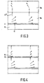
- FIG. 3 A modification in which both retardation foils are situated on one side of the substrate is shown in Fig. 3.
- the molecules 12" of the retardation foil 9 a are homeotropically aligned at the interface between the retardation foils 9 a and 9 b , the homeotropic alignment can be induced in a simple manner in the retardation foil 9 b which is situated above the retardation foil 9 a . If the mixture contains sufficient molecules which tend to assume a planar orientation, then the tilt angle decreases again, so that an average angle of approximately 25 degrees is formed.
- the preferred direction in the retardation foil 9 b is introduced, for example, by mechanical shearing or by covering the entire compensator, during the polymerization operation, with a thin layer (film) provided with an orienting layer.
- the tilt angle in foil 9 b at the interface between the retardation foils 9 a and 9 b is made substantially parallel to the interface by means of a rubbing treatment.
- a thin, transparent, optically isotropic protective layer 15 is provided in order not to disturb the underlying perpendicular alignment.
- the directions of orientation, as shown in Fig. 2 for the layers 9 (combined splay and bend configuration), in which the tilt angle at the free surface may also be smaller than 90 degrees can also be obtained by using a liquid-crystalline starting material which spontaneously adopts such a configuration because the ratio K 11 /W between the elastic constant K 11 and the (polar) anchoring energy coefficient W is chosen to be smaller than 300 nm.
- a substrate After a substrate has been oriented, it is coated, using one of the methods described hereinabove, with the liquid-crystalline material, whereafter a polymerization step is carried out.
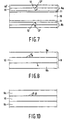
- Fig. 5 shows a variant of the compensator shown in Fig. 2, in which the retardation foils 9 a , 9 b comprise sub-layers 19, 19', 19" and 19'".
- the tilt angles in each one of the sub-layers 19 are substantially the same.
- retardation foil 9' the directions of orientation of the associated molecules (indicated by means of directors 12, 12', 12" and 12'") and hence the optical main axes extend, in this example, in the plane of the drawing and, as regards retardation foil 9 b , in a plane perpendicular to the plane of the drawing.
- the optical main axis of the retardation foil 9 a may alternatively extend in another suitable plane which is unequal to the plane of the drawing.
- the directions of orientation of the associated molecules (indicated by means of directors 12, 12', 12" and 12'") in successive sub-layers 19, 19', 19", 19'" of the retardation foil 9 a make a small angle with each other.
- the optical main axis of the retardation foil 9 a extends in a plane which makes an angle with the plane of the drawing.
- the directions of orientation of the associated molecules (indicated by means of directors 12, 12', 12" and 12'") in successive sub-layers 19, 19', 19", 19'" of the retardation foil 9 b make a small angle with each other.
- the optical main axis of the retardation foil 9 b extends in a plane which makes an angle with the plane at right angles to the plane of the drawing. Both optical main axes cross each other, for example, at an angle ranging between 60 and 120 degrees.
- the directions of orientation of the molecules in successive sub-layers 19 are different at the boundary between two sub-layers, whereas they are substantially equal in the device shown in Fig. 7. Nevertheless, the direction of orientation of director 12' in retardation foil 9 a differs from that of director 12 due to the fact that a small quantity of a chiral component is added to the mixture of liquid-crystalline materials to be polymerized or vitrified.
- the polymerized (vitrified) sub-layer 19 serves as the orientation layer for the sub-layer 19' in a subsequent process step. If necessary, the material of the sub-layer 19' may again contain a small quantity of a chiral component.
- the relevant chiral component may have the same chirality, so that the angle which the optical main axis of the complete retardation foil makes with the plane of the drawing is increased with respect to the angle which the optical main axis of the sublayer 19 makes with the plane of the drawing.
- the angle which optical main axis of the retardation foil makes with the plane of the drawing is reduced; dependent upon the quantity of the chiral component and the thickness of the sub-layer 19', the optical main axis of the complete retardation foil may again extend in the plane of the drawing.
- many intermediate forms are also possible.
- Fig. 8 shows a compensator 9 comprising a transparent support 9 and retardation foils 9 a , 9 b on the two different sides of the support 10, the optical main axes of said retardation foils making an angle (for example a) with the support and cross each other (for example at right angles).
- the retardation foils 9 a , 9 b can be obtained by obliquely vapor-depositing a suitable material, such as tantalum oxide or tungsten oxide.
- a suitable material such as tantalum oxide or tungsten oxide.
- the direction of the optical main axis is determined exclusively by the direction of deposition, the retardation foils can be so provided on both sides of substrate 10 that they include an angle between the optical main axes.
- Other suitable materials are silicon oxide or titanium oxide. Said materials may be provided, for example, on a transparent saw-tooth structure.
- the retardation foils 9 a , 9 b on the two different sides of the support 10 have such a structure that the optical axis of the retardation foil is tilted relative to the normal to the surface of the retardation foil
- one of the two retardation foils may alternatively be constructed as a uniaxial foil, for example, having an optical main axis extending parallel to the support.
- a possible example is shown in Fig. 10.
- a retardation foil 9 a is provided on one side of the support 10, whereas, on the other side, a uniaxial foil 9 c is provided.
- the invention relates to a compensator (for example, for a liquid-crystal display device), which compensator comprises a retardation foil having a tilted optical main axis and, in addition, a second optically active layer, which are provided on different sides of a transparent support, which enables the manufacture to be simplified.
- a compensator for example, for a liquid-crystal display device
- which compensator comprises a retardation foil having a tilted optical main axis and, in addition, a second optically active layer, which are provided on different sides of a transparent support, which enables the manufacture to be simplified.
Landscapes
- Physics & Mathematics (AREA)
- Nonlinear Science (AREA)
- General Physics & Mathematics (AREA)
- Optics & Photonics (AREA)
- Chemical & Material Sciences (AREA)
- Crystallography & Structural Chemistry (AREA)
- Mathematical Physics (AREA)
- Liquid Crystal (AREA)
- Polarising Elements (AREA)
Priority Applications (1)
| Application Number | Priority Date | Filing Date | Title |
|---|---|---|---|
| EP97916609A EP0840904B1 (en) | 1996-05-17 | 1997-04-30 | Compensator |
Applications Claiming Priority (6)
| Application Number | Priority Date | Filing Date | Title |
|---|---|---|---|
| EP96201394 | 1996-05-17 | ||
| EP96201394 | 1996-05-17 | ||
| EP96202718 | 1996-09-30 | ||
| EP96202718 | 1996-09-30 | ||
| PCT/IB1997/000457 WO1997044702A1 (en) | 1996-05-17 | 1997-04-30 | Compensator, liquid-crystal display device and retardation foil |
| EP97916609A EP0840904B1 (en) | 1996-05-17 | 1997-04-30 | Compensator |
Publications (2)
| Publication Number | Publication Date |
|---|---|
| EP0840904A1 EP0840904A1 (en) | 1998-05-13 |
| EP0840904B1 true EP0840904B1 (en) | 2005-08-17 |
Family
ID=26142818
Family Applications (1)
| Application Number | Title | Priority Date | Filing Date |
|---|---|---|---|
| EP97916609A Expired - Lifetime EP0840904B1 (en) | 1996-05-17 | 1997-04-30 | Compensator |
Country Status (7)
| Country | Link |
|---|---|
| US (1) | US5978055A (https=) |
| EP (1) | EP0840904B1 (https=) |
| JP (1) | JPH11509650A (https=) |
| KR (1) | KR100508194B1 (https=) |
| DE (1) | DE69733987T2 (https=) |
| MY (1) | MY126383A (https=) |
| WO (1) | WO1997044702A1 (https=) |
Families Citing this family (36)
| Publication number | Priority date | Publication date | Assignee | Title |
|---|---|---|---|---|
| TW494263B (en) * | 1996-05-17 | 2002-07-11 | Koninkl Philips Electronics Nv | Liquid-crystal display device, compensator layer and method of manufacturing a retardation foil |
| TW373100B (en) * | 1996-07-01 | 1999-11-01 | Merck Patent Gmbh | Compensation film and liquid crystal display device containing the same |
| TW373123B (en) | 1996-07-26 | 1999-11-01 | Merck Patent Gmbh | Combination of optical elements, means to produce substantially linear polarized light, optical retardation film and liquid crystal display device |
| TW472081B (en) * | 1996-09-17 | 2002-01-11 | Merck Patent Gmbh | Optical retardation film |
| US5817199A (en) * | 1996-12-20 | 1998-10-06 | Kimberly-Clark Worldwide, Inc. | Methods and apparatus for a full width ultrasonic bonding device |
| JP4303333B2 (ja) * | 1998-08-21 | 2009-07-29 | 新日本石油株式会社 | 光学素子用フィルム |
| US6538712B1 (en) * | 1999-09-29 | 2003-03-25 | Rockwell Science Center, Llc | High pretilt alignment of reactive liquid crystals in liquid crystal displays |
| US6307607B1 (en) * | 1999-12-21 | 2001-10-23 | Philips Electronics North America Corporation | Reflective liquid crystal display with integrated compensation for skew angle rotation and birefringence effects |
| US6359671B1 (en) * | 2000-02-23 | 2002-03-19 | Planar Systems, Inc. | High contrast liquid crystal device |
| TW522260B (en) * | 2000-04-03 | 2003-03-01 | Konishiroku Photo Ind | Optical compensation sheet and liquid crystal display |
| JP2002207125A (ja) * | 2000-04-03 | 2002-07-26 | Konica Corp | 光学補償シート及び液晶表示装置 |
| US6784961B2 (en) | 2000-05-31 | 2004-08-31 | Sony Corporation | Apparatus and method for displaying image |
| JP4802409B2 (ja) | 2000-07-21 | 2011-10-26 | コニカミノルタホールディングス株式会社 | 光学補償フィルム、それを用いた偏光板及び液晶表示装置 |
| KR20020040996A (ko) * | 2000-11-25 | 2002-05-31 | 주식회사 현대 디스플레이 테크놀로지 | 다층구조의 편광 도광판 |
| US20030090012A1 (en) * | 2001-09-27 | 2003-05-15 | Allen Richard Charles | Methods of making polarization rotators and articles containing the polarization rotators |
| US6985291B2 (en) * | 2001-10-01 | 2006-01-10 | 3M Innovative Properties Company | Non-inverting transflective assembly |
| DE60336184D1 (de) * | 2002-02-06 | 2011-04-14 | Merck Patent Gmbh | Doppelbrechender Film und seine Verwendung |
| EP1335217B1 (en) * | 2002-02-06 | 2011-03-02 | Merck Patent GmbH | Birefringent film and its uses |
| US6919946B2 (en) * | 2002-04-16 | 2005-07-19 | 3M Innovative Properties Company | Compensators for liquid crystal displays and the use and manufacture of the compensators |
| US7193670B2 (en) * | 2002-04-17 | 2007-03-20 | Nitto Denko Corporation | Compensator for liquid crystal display with two compensation sheets |
| EP1376163B1 (en) | 2002-06-27 | 2011-08-17 | Merck Patent GmbH | Process of preparing films comprising polymerised liquid crystal material |
| US6874899B2 (en) * | 2002-07-12 | 2005-04-05 | Eastman Kodak Company | Apparatus and method for irradiating a substrate |
| US6995823B1 (en) * | 2002-07-30 | 2006-02-07 | Rockwell Collins, Inc. | Viewing angle for liquid crystal display system and method |
| US6943930B2 (en) * | 2002-09-12 | 2005-09-13 | Eastman Kodak Company | Method and system for fabricating optical film using an exposure source and reflecting surface |
| EP1556732A4 (en) * | 2002-10-30 | 2006-01-11 | Colorlink Inc | PLATE TILTING COMPENSATORS FOR PROJECTION DISPLAY SYSTEMS |
| US7327432B2 (en) * | 2002-11-02 | 2008-02-05 | Merck Patent Gesellschaft Mit Beschrankter Haftung | Optically compensated electro-optical light modulation element with optically isotropic phase |
| JP2006506679A (ja) * | 2002-11-15 | 2006-02-23 | コーニンクレッカ フィリップス エレクトロニクス エヌ ヴィ | 光学的異方性体 |
| US6844913B2 (en) * | 2003-04-24 | 2005-01-18 | Eastman Kodak Company | Optical exposure apparatus for forming an alignment layer |
| US7075606B2 (en) * | 2003-07-29 | 2006-07-11 | Eastman Kodak Company | Method for manufacturing an optical compensator on a transitional substrate |
| KR101067228B1 (ko) * | 2003-12-30 | 2011-09-26 | 엘지디스플레이 주식회사 | 보상필름, 보상필름의 제조방법 및 이를 이용한액정표시장치 |
| JP2006119444A (ja) * | 2004-10-22 | 2006-05-11 | Fuji Photo Film Co Ltd | 位相差補償素子およびそれを用いた液晶装置 |
| US20070141244A1 (en) * | 2005-12-19 | 2007-06-21 | Eastman Kodak Company | Method of making a polarizer plate |
| US7732007B2 (en) * | 2005-12-19 | 2010-06-08 | Eastman Kodak Company | Method of making a polarizer plate |
| JP2008268372A (ja) * | 2007-04-17 | 2008-11-06 | Fujinon Corp | 位相差補償素子及びその製造方法 |
| EP2108691A1 (en) | 2008-04-11 | 2009-10-14 | Stichting Dutch Polymer Institute | Structured films with a controlled tilted molecular orientation and shape using a dichroic photoinitiator. |
| US11124705B2 (en) | 2017-04-20 | 2021-09-21 | Merck Patent Gmbh | Light modulation element |
Family Cites Families (21)
| Publication number | Priority date | Publication date | Assignee | Title |
|---|---|---|---|---|
| DE3022818C2 (de) * | 1980-06-19 | 1986-11-27 | Merck Patent Gmbh, 6100 Darmstadt | Flüssigkristall-Anzeigeelement |
| FR2595157B1 (fr) * | 1986-02-28 | 1988-04-29 | Commissariat Energie Atomique | Cellule a double couche de cristal liquide, utilisant l'effet de birefringence controlee electriquement et procede de fabrication d'un milieu uniaxe d'anisotropie optique negative utilisable dans cette cellule |
| EP0350075A3 (en) * | 1988-07-08 | 1990-09-05 | Kabushiki Kaisha Toshiba | Liquid crystal display device |
| WO1990011546A1 (en) * | 1989-03-28 | 1990-10-04 | Asahi Glass Company Ltd. | Liquid crystal display device |
| JPH0328822A (ja) * | 1989-06-27 | 1991-02-07 | Nippon Oil Co Ltd | 液晶表示素子用補償板 |
| JP2711585B2 (ja) * | 1990-06-26 | 1998-02-10 | 日本石油株式会社 | アクティブマトリックス液晶表示素子用補償板 |
| JP2660601B2 (ja) * | 1990-06-27 | 1997-10-08 | 日本石油株式会社 | 液晶表示素子用補償板の製造法 |
| NL9001643A (nl) * | 1990-07-19 | 1992-02-17 | Philips Nv | Werkwijze voor het aanbrengen van een orientatielaag in een vloeibaar kristallijne beeldweergeefcel. |
| US5237438A (en) * | 1991-05-02 | 1993-08-17 | Casio Computer Co., Ltd. | Liquid crystal display device |
| US5359443A (en) * | 1991-11-22 | 1994-10-25 | Nippon Oil Company, Limited | Process for producing heat-resistant optical element by heating liquid crystal polymer at polymerization temperature during or after orientation treatment |
| JP2866540B2 (ja) * | 1992-06-26 | 1999-03-08 | シャープ株式会社 | 液晶表示装置 |
| JPH09504382A (ja) * | 1993-09-29 | 1997-04-28 | アクゾ ノーベル ナムローゼ フェンノートシャップ | 能動液晶セルに適合する分散を有する位相遅れ層 |
| US5576861A (en) * | 1993-12-15 | 1996-11-19 | Ois Optical Imaging Systems, Inc. | Liquid crystal display having a retarder with 100-200nm retardation and having high contrast viewing zone centered in positive or negative vertical region |
| US5570214A (en) * | 1993-12-15 | 1996-10-29 | Ois Optical Imaging Systems, Inc. | Normally white twisted nematic LCD with retardation films on opposite sides of liquid crystal material for improved viewing zone |
| JP2927662B2 (ja) * | 1993-12-24 | 1999-07-28 | シャープ株式会社 | 液晶表示装置 |
| DE4408171A1 (de) * | 1994-03-11 | 1995-09-14 | Basf Ag | Neue polymerisierbare flüssigkristalline Verbindungen |
| US5724112A (en) * | 1994-03-28 | 1998-03-03 | Casio Computer Co., Ltd. | Color liquid crystal apparatus |
| US5504603A (en) * | 1994-04-04 | 1996-04-02 | Rockwell International Corporation | Optical compensator for improved gray scale performance in liquid crystal display |
| US5619352A (en) * | 1994-04-04 | 1997-04-08 | Rockwell International Corporation | LCD splay/twist compensator having varying tilt and /or azimuthal angles for improved gray scale performance |
| TW289769B (https=) * | 1994-04-22 | 1996-11-01 | Sumitomo Chemical Co | |
| JP3284169B2 (ja) * | 1995-10-13 | 2002-05-20 | シャープ株式会社 | 複屈折制御型液晶表示装置 |
-
1997
- 1997-04-30 KR KR10-1998-0700329A patent/KR100508194B1/ko not_active Expired - Fee Related
- 1997-04-30 JP JP9541893A patent/JPH11509650A/ja not_active Ceased
- 1997-04-30 WO PCT/IB1997/000457 patent/WO1997044702A1/en not_active Ceased
- 1997-04-30 DE DE69733987T patent/DE69733987T2/de not_active Expired - Fee Related
- 1997-04-30 EP EP97916609A patent/EP0840904B1/en not_active Expired - Lifetime
- 1997-05-14 MY MYPI97002114A patent/MY126383A/en unknown
- 1997-05-15 US US08/857,128 patent/US5978055A/en not_active Expired - Fee Related
Also Published As
| Publication number | Publication date |
|---|---|
| DE69733987T2 (de) | 2006-06-22 |
| WO1997044702A1 (en) | 1997-11-27 |
| KR19990029026A (ko) | 1999-04-15 |
| EP0840904A1 (en) | 1998-05-13 |
| JPH11509650A (ja) | 1999-08-24 |
| KR100508194B1 (ko) | 2005-11-16 |
| DE69733987D1 (de) | 2005-09-22 |
| MY126383A (en) | 2006-09-29 |
| US5978055A (en) | 1999-11-02 |
Similar Documents
| Publication | Publication Date | Title |
|---|---|---|
| EP0840904B1 (en) | Compensator | |
| KR101029933B1 (ko) | 광학 등방성 상을 갖는 광학적으로 보정된 전기-광학 광변조 소자 | |
| EP0839172B1 (en) | Liquid-crystal display device, compensator layer and method of manufacturing a retardation foil | |
| US7405786B2 (en) | Laminated retardation optical element, process of producing the same, and liquid crystal display | |
| JPH1172621A (ja) | 光学デバイス | |
| US7352422B2 (en) | Retardation optical element and method of producing the same, and polarization element and liquid crystal display, each including retardation optical element | |
| KR970706520A (ko) | 트위스티드 네마틱 액정표시장치에서의 그레이 스케일 성능 개선을 위한 유기 폴리머 o-판 보상기(organic polymer o-plate compensator for improved gray scale performance in twisted nematic liquid crystal displays) | |
| US5855986A (en) | Liquid crystal display device and retardation foil | |
| EP0865630A1 (en) | Liquid-crystal display device and optical component comprising a polarizer | |
| JP3358815B2 (ja) | 液晶表示装置及びリタデーションフォイル | |
| JP4420818B2 (ja) | 負のリタデーションフィルムおよび線形偏光子からなる積層体 | |
| KR20040025862A (ko) | A 플레이트 또는 o 플레이트 위상차 필름을 포함하는 신모드 액정 디스플레이 | |
| US7193670B2 (en) | Compensator for liquid crystal display with two compensation sheets | |
| JP2004145268A (ja) | 位相差光学素子及びその製造方法、並びに位相差光学素子を備えた偏光素子及び液晶表示装置 | |
| EP0725943B1 (en) | Liquid crystal display device and retardation foil |
Legal Events
| Date | Code | Title | Description |
|---|---|---|---|
| PUAI | Public reference made under article 153(3) epc to a published international application that has entered the european phase |
Free format text: ORIGINAL CODE: 0009012 |
|
| AK | Designated contracting states |
Kind code of ref document: A1 Designated state(s): DE FR GB NL |
|
| 17P | Request for examination filed |
Effective date: 19980527 |
|
| 17Q | First examination report despatched |
Effective date: 20040701 |
|
| GRAP | Despatch of communication of intention to grant a patent |
Free format text: ORIGINAL CODE: EPIDOSNIGR1 |
|
| RTI1 | Title (correction) |
Free format text: COMPENSATOR |
|
| GRAS | Grant fee paid |
Free format text: ORIGINAL CODE: EPIDOSNIGR3 |
|
| GRAA | (expected) grant |
Free format text: ORIGINAL CODE: 0009210 |
|
| AK | Designated contracting states |
Kind code of ref document: B1 Designated state(s): DE FR GB NL |
|
| REG | Reference to a national code |
Ref country code: GB Ref legal event code: FG4D |
|
| REF | Corresponds to: |
Ref document number: 69733987 Country of ref document: DE Date of ref document: 20050922 Kind code of ref document: P |
|
| PGFP | Annual fee paid to national office [announced via postgrant information from national office to epo] |
Ref country code: GB Payment date: 20060425 Year of fee payment: 10 |
|
| PGFP | Annual fee paid to national office [announced via postgrant information from national office to epo] |
Ref country code: FR Payment date: 20060426 Year of fee payment: 10 |
|
| PGFP | Annual fee paid to national office [announced via postgrant information from national office to epo] |
Ref country code: NL Payment date: 20060430 Year of fee payment: 10 |
|
| ET | Fr: translation filed | ||
| PGFP | Annual fee paid to national office [announced via postgrant information from national office to epo] |
Ref country code: DE Payment date: 20060619 Year of fee payment: 10 |
|
| PLBE | No opposition filed within time limit |
Free format text: ORIGINAL CODE: 0009261 |
|
| STAA | Information on the status of an ep patent application or granted ep patent |
Free format text: STATUS: NO OPPOSITION FILED WITHIN TIME LIMIT |
|
| 26N | No opposition filed |
Effective date: 20060518 |
|
| GBPC | Gb: european patent ceased through non-payment of renewal fee |
Effective date: 20070430 |
|
| NLV4 | Nl: lapsed or anulled due to non-payment of the annual fee |
Effective date: 20071101 |
|
| PG25 | Lapsed in a contracting state [announced via postgrant information from national office to epo] |
Ref country code: NL Free format text: LAPSE BECAUSE OF NON-PAYMENT OF DUE FEES Effective date: 20071101 Ref country code: DE Free format text: LAPSE BECAUSE OF NON-PAYMENT OF DUE FEES Effective date: 20071101 |
|
| PG25 | Lapsed in a contracting state [announced via postgrant information from national office to epo] |
Ref country code: GB Free format text: LAPSE BECAUSE OF NON-PAYMENT OF DUE FEES Effective date: 20070430 |
|
| PG25 | Lapsed in a contracting state [announced via postgrant information from national office to epo] |
Ref country code: FR Free format text: LAPSE BECAUSE OF NON-PAYMENT OF DUE FEES Effective date: 20070430 |