EP0840898B1 - Method for broadband decoupling in nuclear magnetic resonance with chirp pulses - Google Patents
Method for broadband decoupling in nuclear magnetic resonance with chirp pulses Download PDFInfo
- Publication number
- EP0840898B1 EP0840898B1 EP96924515A EP96924515A EP0840898B1 EP 0840898 B1 EP0840898 B1 EP 0840898B1 EP 96924515 A EP96924515 A EP 96924515A EP 96924515 A EP96924515 A EP 96924515A EP 0840898 B1 EP0840898 B1 EP 0840898B1
- Authority
- EP
- European Patent Office
- Prior art keywords
- pulses
- chirp
- cycle
- chirp pulses
- defining
- Prior art date
- Legal status (The legal status is an assumption and is not a legal conclusion. Google has not performed a legal analysis and makes no representation as to the accuracy of the status listed.)
- Expired - Lifetime
Links
- 238000000034 method Methods 0.000 title claims abstract description 34
- 238000005481 NMR spectroscopy Methods 0.000 title abstract description 6
- 230000005415 magnetization Effects 0.000 claims abstract description 19
- 230000003068 static effect Effects 0.000 claims abstract description 6
- 230000004044 response Effects 0.000 claims abstract description 4
- 238000010168 coupling process Methods 0.000 claims description 15
- 238000005859 coupling reaction Methods 0.000 claims description 15
- 230000008878 coupling Effects 0.000 claims description 13
- 230000000630 rising effect Effects 0.000 claims description 3
- 239000000523 sample Substances 0.000 description 23
- 238000001228 spectrum Methods 0.000 description 14
- BDAGIHXWWSANSR-UHFFFAOYSA-N methanoic acid Natural products OC=O BDAGIHXWWSANSR-UHFFFAOYSA-N 0.000 description 11
- 230000006870 function Effects 0.000 description 7
- 235000019253 formic acid Nutrition 0.000 description 6
- OSWFIVFLDKOXQC-UHFFFAOYSA-N 4-(3-methoxyphenyl)aniline Chemical compound COC1=CC=CC(C=2C=CC(N)=CC=2)=C1 OSWFIVFLDKOXQC-UHFFFAOYSA-N 0.000 description 5
- 238000002474 experimental method Methods 0.000 description 5
- 239000000126 substance Substances 0.000 description 4
- OKTJSMMVPCPJKN-OUBTZVSYSA-N Carbon-13 Chemical compound [13C] OKTJSMMVPCPJKN-OUBTZVSYSA-N 0.000 description 3
- 238000001727 in vivo Methods 0.000 description 3
- 239000002131 composite material Substances 0.000 description 2
- 238000010586 diagram Methods 0.000 description 2
- 230000005284 excitation Effects 0.000 description 2
- 230000003595 spectral effect Effects 0.000 description 2
- 230000007480 spreading Effects 0.000 description 2
- 101710093674 Cyclic nucleotide-gated cation channel beta-1 Proteins 0.000 description 1
- PXGOKWXKJXAPGV-UHFFFAOYSA-N Fluorine Chemical compound FF PXGOKWXKJXAPGV-UHFFFAOYSA-N 0.000 description 1
- 238000000292 Malcolm Levitt pulse sequence Methods 0.000 description 1
- 102100025946 Transforming growth factor beta activator LRRC32 Human genes 0.000 description 1
- 101710169732 Transforming growth factor beta activator LRRC32 Proteins 0.000 description 1
- 239000007864 aqueous solution Substances 0.000 description 1
- 230000008901 benefit Effects 0.000 description 1
- 238000010276 construction Methods 0.000 description 1
- 230000007423 decrease Effects 0.000 description 1
- 230000000694 effects Effects 0.000 description 1
- 238000003881 globally optimized alternating phase rectangular pulse Methods 0.000 description 1
- 238000010438 heat treatment Methods 0.000 description 1
- 238000002955 isolation Methods 0.000 description 1
- 230000000155 isotopic effect Effects 0.000 description 1
- 229920002521 macromolecule Polymers 0.000 description 1
- 238000000819 phase cycle Methods 0.000 description 1
- 238000004088 simulation Methods 0.000 description 1
- 238000010408 sweeping Methods 0.000 description 1
- 230000007704 transition Effects 0.000 description 1
- 238000001969 wideband alternating-phase low-power technique for zero residual splitting Methods 0.000 description 1
Images



Classifications
-
- G—PHYSICS
- G01—MEASURING; TESTING
- G01R—MEASURING ELECTRIC VARIABLES; MEASURING MAGNETIC VARIABLES
- G01R33/00—Arrangements or instruments for measuring magnetic variables
- G01R33/20—Arrangements or instruments for measuring magnetic variables involving magnetic resonance
- G01R33/44—Arrangements or instruments for measuring magnetic variables involving magnetic resonance using nuclear magnetic resonance [NMR]
- G01R33/46—NMR spectroscopy
- G01R33/4616—NMR spectroscopy using specific RF pulses or specific modulation schemes, e.g. stochastic excitation, adiabatic RF pulses, composite pulses, binomial pulses, Shinnar-le-Roux pulses, spectrally selective pulses not being used for spatial selection
Definitions
- This invention relates generally to a method and apparatus for broadband decoupling scalar or dipolar couplings between nuclei in a sample by inverting a longitudinal magnetization in the sample with cycles of chirp pulses.
- the bandwidths that must be covered are increasing.
- a bandwidth of 50kHz is required for decoupling carbon-13 spectra of 200ppm width.
- decoupling methods must also be very tolerant to RF inhomogeneity.
- the objects of the present invention are to provide an improved method for decoupling scalar or dipolar couplings over virtually unlimited bandwidths; the provision of such method for decoupling scalar or dipolar couplings using chirp pulses in cycles and supercycles; the provision of such method for decoupling scalar or dipolar couplings using chirp pulses with linear frequency modulation; the provision of such method for decoupling scalar or dipolar couplings with limited RF power; the provision of such method for decoupling scalar or dipolar couplings using apodized RF amplitudes; the provision of such method for decoupling which is tolerant of RF inhomogeneity and gives narrow residual linewidths and weak modulation sidebands; and the provision of such method which is reliable and easy to use.
- a method of the present invention is performed for decoupling a scalar or dipolar coupling between nuclei in a sample by inverting a longitudinal magnetization in the sample.
- the method includes the step of positioning the sample in a static magnetic field.
- the method also includes the steps of defining a first cycle of chirp pulses wherein at least two of the chirp pulses in the first cycle have a different initial phase angle from each other and defining a second cycle of chirp pulses wherein at least two of the chirp pulses in the second cycle have an initial phase angle different from the initial phase angles of chirp pulses in the first cycle.
- the method also includes the step of generating a supercycle comprising a plurality of the first and second cycles so that the first and second cycles are repeatedly generated as a function of the supercycle. This produces chirp pulses for inverting the longitudinal magnetization in the sample. The signals emitted by the sample in response to inversion of the longitudinal magnetization are detected.
- Chirp pulses used in the method are defined to have a linear frequency sweep or an equivalent phase variation, and a substantially constant RF amplitude, which may or may not be apodized at the rising and falling edges of the pulses.
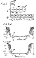
- Figs. 1(a-b) show the waveshapes of chirp pulses that are useful for broadband adiabatic inversion of the longitudinal magnetization in a sample.
- a dotted line 40 in Figs. 1(a-b) shows the carrier frequency ⁇ RF of the waveshapes.
- the scale for dotted line 40 appears along the right side measured in kHz.
- the chirp pulses may be set to their central frequency (such as the Larmor frequency as explained below) indicated at zero in Figs. 1(a-b) while the phase is varied.
- the phase may be varied by integrating the frequency offset between the central frequency and the carrier frequency to be swept.
- the phase is measured relative to a frame rotating at the central frequency and is programmed as a function of time.
- Dashed lines 44 and 46 show the time dependence of the RF amplitude of the chirp pulses shown in Figs. 1(a) and (b), respectively.
- the scale for dashed lines 44 and 46 appears along the left side measured in kHz.
- the chirp pulse shown in Fig. 1(b) is a linear chirp pulse combined with an RF amplitude profile which has been apodized in the initial and final 10% using a half-Gaussian envelope truncated at 2.5%.
- a chirp pulse may be defined as a pulse having a linear frequency sweep as shown by dotted line 40 and a substantially constant amplitude which may or may not be apodized as shown by dashed lines 44 and 46.
- the simple linear chirp pulse of Fig. 1(a) with a constant RF amplitude has the advantage that there is no need for a linear amplifier.
- a disadvantage to this pulse is that the adiabatic condition is not easily fulfilled when the RF carrier frequency sweeps through resonance. If the RF field is too weak, the magnetization may not closely follow the effective field as it rotates from the north pole to the south pole of the accelerating rotating frame. On the other hand, a large constant RF amplitude throughout the sweep leads to violations of adiabacity at the beginning of the chirp pulse.
- Fig. 2 shows a basic chirp unit 58 for decoupling scalar or dipolar couplings between nuclei in a sample by inverting a longitudinal magnetization in the sample with cycles of chirp pulses.
- Chirp unit 58 is a linear frequency modulated chirp pulse of duration ⁇ .
- Chirp unit 58 may take the form of either of the chirp pulses shown in Figs. 1(a-b).
- Fig. 2 also shows five chirp units, 60, 62, 64, 66 and 68 combined together in a five step cycle to define a chirp cycle R of duration 5 ⁇ .
- Chirp units 60-68 are similar to each other with the exception that their respective initial phases are shifted.
- Chirp units 60 and 68 have an initial phase of about zero radians as shown in Figs. 1(a-b).
- Chirp units 62 and 66 have an initial phase of about 150 degrees (which is converted to radians for use with the scales shown in Figs. 1(a-b)).
- Chirp unit 64 has an initial phase of about 60 degrees (which is also converted to radians for use with the scales shown in Figs. 1(a-b)).
- chirp cycle R comprises a series of chirp pulses or units.
- the inverse of the chirp cycle is defined by using the identical chirp units 60-68 as in chirp cycle R except that the initial phases of each of the chirp units are advanced about 180 degrees.
- the first and fifth chirp units in the inverse chirp cycle have an initial phase angle of about 180 degrees
- the second and fourth chirp units in the inverse chirp cycle have an initial phase angle of about 330 degrees
- the third chirp unit in the inverse chirp cycle has an initial phase angle of about 240 degrees.
- inverse chirp cycle comprises a second series of chirp pulses or units.
- Each supercycle 70 comprises a total of sixteen cycles R and .
- the first cycle R fills positions 1, 2, 6, 7, 11, 12, 13 and 16 of supercycle 70 as these positions have been numbered in Fig. 2.
- the second cycle fills positions 3, 4, 5, 8, 9, 10, 14 and 15 of supercycle 70 as these positions have been numbered in Fig. 2.
- the first cycle R may be defined as a first cycle of linear frequency modulated RF pulses wherein each of the RF pulses has an amplitude which is substantially constant during at least about 50% of said pulses.
- the second cycle may be defined as a second cycle of linear frequency modulated RF pulses wherein each of the RF pulses has an amplitude which is substantially constant during at least about 50% of said pulses.
- Each of the RF pulses in the first and second cycles may have an amplitude below about 10kHz. In some cases, the amplitudes of the pulses may by maintained below about 6kHz and in still others below about 4kHz.
- a method for decoupling the scalar or dipolar couplings in a sample may include the steps of providing a static magnetic field and positioning the sample in the static magnetic field.
- the signals emitted by the sample in response to inversion of the longitudinal magnetization are then detected with a suitable detector in the spectrometer.
- Figs. 3(a) and (b) are inversion profiles showing the expectation value ⁇ M z > as a function of offset for the chirp pulses shown in Figs. 1(a) and (b), respectively.
- solid lines 72 and 74 show the inversion profiles for a single one of the chirp pulses shown in Figs. 1(a) and (b), respectively, taken in isolation and swept from -30 to +30kHz.
- solid lines 72 and 74 are the inversion profiles for these pulses without consideration of chirp cycles R and or of supercycles 70.
- An inversion value of -1 corresponds to complete population inversion.
- An inversion value of 1 corresponds to a sample at equilibrium.
- Dashed lines 76 and 78 show the inversion profiles when chirp cycle R is used.
- Dashed line 76 corresponds to the situation where chirp cycle R is constructed using the chirp pulse shown in Fig. 1(a)
- dashed line 78 corresponds to the situation where chirp cycle R is constructed using the chirp pulse shown in Fig. 1(b).
- Figs. 3(a-b) thus show that the chirp pulses of Figs. 1(a-b) allow one to invert the longitudinal magnetization over a very broad frequency range.
- the adiabatic condition may not be properly fulfilled using the single chirp pulse of Fig. 1(a). This may cause poor inversion performance as shown by solid line 72 in Fig. 3(a). However, this inversion performance can be dramatically improved by using a five step cycle R as shown by dashed line 76. Because the chirp pulse of Fig. 1(b) has an apodized RF amplitude at the rising and falling edges, this pulse has an improved inversion performance as shown by solid line 74. However, this improved inversion performance comes at the expense of a narrowed bandwidth as shown in Fig. 3(b). The five step cycle R causes a slight extension of the inversion bandwidth as shown by dashed line 78.
- the simple chirp pulse of Fig. 1(a) was used in combination with chirp cycles R and and 80 step supercycle 7.0 for each of Figs. 4(a-c).
- a single 13 C 90 degree observation pulse was also generated prior to generation of the supercycles 70 to condition the sample.
- the amplitudes of the chirp pulses used in Figs. 4(a-c) varied.
- the amplitude of the chirp pulse for Fig. 4 (a) was 3.3kHz
- for Fig. 4(b) was 4.2kHz
- Fig. 4(c) was 8.2kHz.
- the effective decoupling bandwidth ⁇ eff is 52kHz in Figs. 4(a-b) and is 50kHz in Fig. 4(c).
- the ratio ⁇ eff / ⁇ RF is an important figure of merit for decoupling. This ratio is 15.8 for Fig. 4(a), 12.4 for Fig. 4(b), and 6.1 for Fig. 4(c). The ratio of the effective decoupling bandwidth over the bandwidth of the RF sweep is approximately 0.87 for Figs. 4(a-c). After exponential broadening of 0.3Hz used in all experiments, the linewidth was 0.74Hz in Fig. 4(a), 0.76Hz in Fig. 4(b), and 0.82Hz in Fig. 4(c). The 13 C linewidth of the undecoupled doublet was 0.74Hz.
- Figs. 5 (a-c) show expanded views of the center of the range of the signals shown in Figs. 4(a-c).
- Fig. 5(a) shows the center line of the spectra shown in Fig. 4(a) without magnification.
- Fig. 5(a') shows the same center line but magnified six times.
- Figs. 5 (b) and (c) show the center line of the spectra shown in Figs. 4(b) and (c), respectively, again magnified six times.
- Figs. 5(a-c) The magnified views of Figs. 5(a-c) more clearly show the sidebands due to the chirp cycles R and and the supercycle 70.
- the parameters of a chirp pulse must be chosen depending on the range of chemical shifts to be decoupled and on the magnitude of the heteronuclear scalar coupling constant J .
- the use of higher RF amplitudes and shorter pulses may be necessary.
- the duration ⁇ of the individual chirp pulses should be much shorter than 1/ J .
- the optimum RF amplitude of a linear chirp pulse is related to the bandwidth and to the duration ⁇ of the chirp pulse as follows: ⁇ RF,opt ⁇ a 1/2
- the bandwidth can also be doubled by keeping the same RF amplitude but doubling the pulse length and assuming that the sideband intensities remain reasonably small.
- the chirp pulses used for collecting the data shown in Fig. 6 were of the general form shown in Fig. 1(a) but using different parameters.
- the pulse width ⁇ for these chirp pulses was 1.2msec.
- the time slice or time increment was 1.17 microseconds using 1024 digital points as compared to the 3.9 microseconds time increment reported above.
- the effective decoupling bandwidth ⁇ eff was 202kHz for an effective decoupling bandwidth ratio ⁇ eff / ⁇ RF of 30.1.
- the chirp pulses were organized into the cycles and supercycle shown in Fig. 2.
- a single 13 C 90 degree observation pulse was generated prior to generation of the supercycles.
- the 220kHz frequency sweep was implemented by setting the chirp pulses to the central frequency and varying the phase instead of varying the frequency over the 220kHz bandwidth.
- the RF amplitude may be much larger than the threshold.
- simple linear chirp pulses with constant amplitudes may not be very effective because the adiabatic condition can be severely violated.
- Apodization improves adiabatic behavior during the inversion of magnetization. Simulations of high power levels above levels that might not be safe for high-resolution probes, e.g. , 20kHz, show that a simple chirp pulse degrades near the ends of the sweep.
- Apodization improves the decoupling efficiency significantly even though the effective decoupling bandwidth decreases from 52 to 48kHz.
- the decoupling efficiency is remarkably tolerant of variations in the RF amplitude. This compares favorably with composite pulse decoupling methods where the efficiency depends critically on the calibration of the RF amplitude. Chirp decoupling should therefore be useful for in vivo NMR where the RF field is often very inhomogenous. By using chirp decoupling sequences, uniform decoupling in a large sample volume is possible.
- the waveforms of the chirp pulses can be programmed with MATLAB via a programming tool 104 and are transferred directly to a memory 106 in spectrometer 100.
- the decoupling sequences may be applied to the 1 H during the acquisition of the 13 C signals.
- the decoupling sequences may also be applied to the 13 C during the acquisition of the 1 H signals.
- Other combinations of nuclei are also possible.
- 32 scans were accumulated with a recycle time of 3 seconds.
- a Lorentzian line-broadening factor of 0.3Hz was applied for all spectra.
- the radio frequency amplitudes were separately calibrated with square pulses using the same attenuation levels as for decoupling.
- the experimental results shown in Fig. 6 can also be obtained with the apparatus and sample shown in Fig. 7.
- the low decoupling amplitude of 6.7kHz protects the high resolution probe in spectrometer 100.
- the decoupling amplitude is preferably set below about 10kHz and, as here, may be below 7kHz.
- the center of the frequency sweep for the chirp pulses was set to the Larmor frequency, 300.13MHz. It is seen then that the invention can be practiced using chirp pulses having a frequency sweep of at least about 100kHz, 150kHz and 200kHz. Even broader frequency sweeps are also contemplated within the scope of the invention as required by the range of the chemical shift to be decoupled.
Landscapes
- Physics & Mathematics (AREA)
- Spectroscopy & Molecular Physics (AREA)
- High Energy & Nuclear Physics (AREA)
- Condensed Matter Physics & Semiconductors (AREA)
- General Physics & Mathematics (AREA)
- Magnetic Resonance Imaging Apparatus (AREA)
- Crystals, And After-Treatments Of Crystals (AREA)
- Electrotherapy Devices (AREA)
- Amplifiers (AREA)
Abstract
Description

Claims (7)
- A method of decoupling a scalar or dipolar coupling between nuclei in a sample by inverting a longitudinal magnetization in the sample, the method comprising the steps of:characterized in thatpositioning the sample in a static magnetic field;defining a first cycle of chirp pulses, at least two of said chirp pulses in the first cycle having a different initial phase angle from each other;defining a second cycle of chirp pulses, at least two of said chirp pulses in the second cycle having an initial phase angle different from the initial phase angles of chirp pulses in the first cycle;generating a supercycle comprising a plurality of the first and second cycles so that the first and second cycles are repeatedly generated as a function of the supercycle to produce chirp pulses for inverting the longitudinal magnetization in the sample; anddetecting the signals emitted by the sample in response to inversion of the longitudinal magnetization,
the chirp pulses are defined to have a linear frequency sweep, or an equivalent phase variation, and a substantially constant RF amplitude, which may or may not be apodized at the rising and falling edges of the pulses. - The method of claim 1 wherein the first mentioned defining step comprises the step of defining the first cycle of chirp pulses to include a plurality of chirp pulses which vary in phase or frequency to result in a frequency sweep of at least about 200kHz in less than about 1.5 milliseconds.
- The method of claim 1 wherein the first mentioned defining step comprises the step of defining the first cycle of chirp pulses to include a plurality of chirp pulses which vary in phase or frequency to result in a frequency sweep of at least about 60kHz in about one millisecond.
- The method of claim 1 wherein
the first mentioned defining step comprises the step of defining the first cycle of chirp pulses to have a varying phase or varying frequency to result in a linear frequency sweep of at least about 100kHz;
the second mentioned defining step comprises the step of defining the second cycle of chirp pulses to have a varying phase or varying frequency to result in a linear frequency sweep of at least about 100kHz. - The method of claim 4 wherein the first mentioned defining step comprises the step of defining the first cycle of chirp pulses to have a varying phase or varying frequency to result in a linear frequency sweep of at least about 150kHz.
- The method of claim 4 or 5 wherein the first mentioned defining step comprises the step of defining the first cycle wherein each of the chirp pulses in the first cycle has an amplitude below about 10kHz.
- The method of anyone of claims 4 through 6 wherein the first mentioned defining step comprises the step of defining the first cycle wherein each of the chirp pulses in the first cycle has a duration less than about 1.5 milliseconds.
Applications Claiming Priority (3)
| Application Number | Priority Date | Filing Date | Title |
|---|---|---|---|
| US504171 | 1995-07-19 | ||
| US08/504,171 US5581182A (en) | 1995-07-19 | 1995-07-19 | Method and apparatus for broadband decoupling in nuclear magnetic resonance with chirp pulses |
| PCT/US1996/011731 WO1997003548A2 (en) | 1995-07-19 | 1996-07-15 | Method and apparatus for broadband decoupling in nuclear magnetic resonance with chirp pulses |
Publications (3)
| Publication Number | Publication Date |
|---|---|
| EP0840898A2 EP0840898A2 (en) | 1998-05-13 |
| EP0840898A4 EP0840898A4 (en) | 2000-01-26 |
| EP0840898B1 true EP0840898B1 (en) | 2005-03-16 |
Family
ID=24005156
Family Applications (1)
| Application Number | Title | Priority Date | Filing Date |
|---|---|---|---|
| EP96924515A Expired - Lifetime EP0840898B1 (en) | 1995-07-19 | 1996-07-15 | Method for broadband decoupling in nuclear magnetic resonance with chirp pulses |
Country Status (6)
| Country | Link |
|---|---|
| US (1) | US5581182A (en) |
| EP (1) | EP0840898B1 (en) |
| AT (1) | ATE291236T1 (en) |
| AU (1) | AU6494596A (en) |
| DE (1) | DE69634485T2 (en) |
| WO (1) | WO1997003548A2 (en) |
Families Citing this family (7)
| Publication number | Priority date | Publication date | Assignee | Title |
|---|---|---|---|---|
| US6294914B1 (en) * | 1993-06-02 | 2001-09-25 | The Board Of Trustees Of The University Of Illinois | Method of enhancing an MRI signal |
| US6064207A (en) * | 1996-07-26 | 2000-05-16 | Varian Associates, Inc. | Adiabatic pulses for wideband inversion and broadband decoupling |
| CN101228455A (en) * | 2005-06-16 | 2008-07-23 | 皇家飞利浦电子股份有限公司 | Low Power Decoupling for Multicore Spectroscopy |
| WO2007121021A1 (en) * | 2006-04-11 | 2007-10-25 | Koninklijke Philips Electronics, N.V. | Low power broadband spin decoupling |
| US9069048B2 (en) * | 2008-12-22 | 2015-06-30 | Koninklijke Philips N.V. | Broadband decoupling pulse trains with interleaved pauses for magnetic resonance spectroscopy |
| CN103354908B (en) * | 2011-02-15 | 2016-07-06 | 皇家飞利浦有限公司 | Method, apparatus and apparatus for wide bandwidth magnetic resonance spectroscopy at high static (B0) magnetic fields using polarization transfer |
| IL297126B2 (en) | 2019-03-25 | 2025-02-01 | Promaxo Inc | Systems and methods for volumetric acquisition in a single-sided mri system |
Family Cites Families (8)
| Publication number | Priority date | Publication date | Assignee | Title |
|---|---|---|---|---|
| US4443761A (en) * | 1981-06-16 | 1984-04-17 | National Research Development Corporation | NMR Spectroscopy |
| US4470014A (en) * | 1982-03-26 | 1984-09-04 | National Research Development Corporation | NMR Spectroscopy |
| US4682106A (en) * | 1985-03-21 | 1987-07-21 | General Electric Company | Methods of, and apparatus for, proton decoupling in nuclear magnetic resonance spectroscopy |
| NL8802036A (en) * | 1988-08-17 | 1990-03-16 | Philips Nv | METHOD FOR METHODIC LINKAGE IN MAGNETIC RESONANCE SPECTROSCOPY AND DEVICE FOR DETERMINING A SPECTRUM. |
| DE68914440T2 (en) * | 1989-04-22 | 1994-07-28 | Spectrospin Ag | Method for excitation of the transverse magnetization in magnetic nuclear magnetic resonance pulse experiments. |
| US5073752A (en) * | 1990-04-19 | 1991-12-17 | Picker International, Inc. | Discrete fourier transform imaging |
| WO1992001235A1 (en) * | 1990-07-11 | 1992-01-23 | Spectrospin Ag | Multiple-quantum nmr with frequency-modulated chirp pulses |
| US5384573A (en) * | 1990-10-29 | 1995-01-24 | Essex Corporation | Image synthesis using time sequential holography |
-
1995
- 1995-07-19 US US08/504,171 patent/US5581182A/en not_active Expired - Lifetime
-
1996
- 1996-07-15 AT AT96924515T patent/ATE291236T1/en not_active IP Right Cessation
- 1996-07-15 WO PCT/US1996/011731 patent/WO1997003548A2/en not_active Ceased
- 1996-07-15 DE DE69634485T patent/DE69634485T2/en not_active Expired - Lifetime
- 1996-07-15 AU AU64945/96A patent/AU6494596A/en not_active Abandoned
- 1996-07-15 EP EP96924515A patent/EP0840898B1/en not_active Expired - Lifetime
Also Published As
| Publication number | Publication date |
|---|---|
| US5581182A (en) | 1996-12-03 |
| EP0840898A4 (en) | 2000-01-26 |
| ATE291236T1 (en) | 2005-04-15 |
| WO1997003548A2 (en) | 1997-02-06 |
| WO1997003548A3 (en) | 1997-04-10 |
| AU6494596A (en) | 1997-02-18 |
| DE69634485T2 (en) | 2006-04-13 |
| DE69634485D1 (en) | 2005-04-21 |
| EP0840898A2 (en) | 1998-05-13 |
Similar Documents
| Publication | Publication Date | Title |
|---|---|---|
| Shrot et al. | Spatially encoded NMR and the acquisition of 2D magnetic resonance images within a single scan | |
| Freeman et al. | Two-dimensional Fourier transformation in NMR | |
| Scholz et al. | MIRROR recoupling and its application to spin diffusion under fast magic-angle spinning | |
| Kupče et al. | Fast multi-dimensional Hadamard spectroscopy | |
| EP0209375B1 (en) | High dynamic range in nmr data acquisition | |
| Gan | Satellite transition magic-angle spinning nuclear magnetic resonance spectroscopy of half-integer quadrupolar nuclei | |
| Fu et al. | Broadband decoupling in NMR with frequency-modulated ‘chirp’pulses | |
| Vinogradov et al. | A bimodal Floquet analysis of phase modulated Lee–Goldburg high resolution proton magic angle spinning NMR experiments | |
| EP0248039B1 (en) | Nmr measurement by controlling the effective magnetic field | |
| EP1344078B1 (en) | Decoupling sideband resolved nmr spectroscopy (desire) | |
| Amoureux et al. | Increasing the sensitivity of 2D high-resolution NMR methods applied to quadrupolar nuclei | |
| Rocha et al. | Progress in multiple-quantum magic-angle spinning NMR spectroscopy | |
| EP0209374B1 (en) | Nmr phase encoding using phase-varying rf pulses | |
| US7948235B2 (en) | Low power broadband spin decoupling | |
| Edén et al. | Excitation of carbon-13 triple quantum coherence in magic-angle-spinning NMR | |
| EP0394504B1 (en) | A method for exciting transverse magnetization in NMR pulse experiments | |
| EP0478632B1 (en) | Nuclear magnetic resonance imaging methods | |
| Schmidt-Rohr | Complete Dipolar Decoupling of13C and Its Use in Two-Dimensional Double-Quantum Solid-State NMR for Determining Polymer Conformations | |
| US5581182A (en) | Method and apparatus for broadband decoupling in nuclear magnetic resonance with chirp pulses | |
| Gan et al. | 14N overtone nuclear magnetic resonance of rotating solids | |
| EP2378281A1 (en) | A method to measure electron relaxation times T1 in EPR tomography and a system for applying the method | |
| EP0601229B1 (en) | A method for exciting transverse magnetisation in magnetic resonance | |
| Bendall | Heteronuclear J coupling precession during spin-lock and adiabatic pulses. Use of adiabatic inversion pulses in high-resolution NMR | |
| US6396267B1 (en) | Polarization transfer by cross-correlated relaxation in solution NMR with very large molecules | |
| Liu et al. | Three-dimensional maximum-quantum correlation HMQC NMR spectroscopy (3D MAXY-HMQC) |
Legal Events
| Date | Code | Title | Description |
|---|---|---|---|
| PUAI | Public reference made under article 153(3) epc to a published international application that has entered the european phase |
Free format text: ORIGINAL CODE: 0009012 |
|
| 17P | Request for examination filed |
Effective date: 19980113 |
|
| AK | Designated contracting states |
Kind code of ref document: A2 Designated state(s): AT BE CH DE DK ES FI FR GB GR IE IT LI LU MC NL PT SE |
|
| RAP1 | Party data changed (applicant data changed or rights of an application transferred) |
Owner name: SPECTROSPIN AG |
|
| RAP1 | Party data changed (applicant data changed or rights of an application transferred) |
Owner name: BRUKER AG |
|
| RIC1 | Information provided on ipc code assigned before grant |
Free format text: 7G 01R 33/20 A, 7G 01R 33/46 B |
|
| A4 | Supplementary search report drawn up and despatched |
Effective date: 19991214 |
|
| AK | Designated contracting states |
Kind code of ref document: A4 Designated state(s): AT BE CH DE DK ES FI FR GB GR IE IT LI LU MC NL PT SE |
|
| RAP1 | Party data changed (applicant data changed or rights of an application transferred) |
Owner name: BRUKER BIOSPIN AG |
|
| 17Q | First examination report despatched |
Effective date: 20040322 |
|
| GRAP | Despatch of communication of intention to grant a patent |
Free format text: ORIGINAL CODE: EPIDOSNIGR1 |
|
| RTI1 | Title (correction) |
Free format text: METHOD FOR BROADBAND DECOUPLING IN NUCLEAR MAGNETIC RESONANCE WITH CHIRP PULSES |
|
| RIN1 | Information on inventor provided before grant (corrected) |
Inventor name: BODENHAUSEN, GEOFFREY - SLIGER BUILDING Inventor name: FU, RIQIANG - SLIGER BUILDING |
|
| GRAS | Grant fee paid |
Free format text: ORIGINAL CODE: EPIDOSNIGR3 |
|
| GRAA | (expected) grant |
Free format text: ORIGINAL CODE: 0009210 |
|
| AK | Designated contracting states |
Kind code of ref document: B1 Designated state(s): AT BE CH DE DK ES FI FR GB GR IE IT LI LU MC NL PT SE |
|
| PG25 | Lapsed in a contracting state [announced via postgrant information from national office to epo] |
Ref country code: NL Free format text: LAPSE BECAUSE OF FAILURE TO SUBMIT A TRANSLATION OF THE DESCRIPTION OR TO PAY THE FEE WITHIN THE PRESCRIBED TIME-LIMIT Effective date: 20050316 Ref country code: IT Free format text: LAPSE BECAUSE OF FAILURE TO SUBMIT A TRANSLATION OF THE DESCRIPTION OR TO PAY THE FEE WITHIN THE PRESCRIBED TIME-LIMIT;WARNING: LAPSES OF ITALIAN PATENTS WITH EFFECTIVE DATE BEFORE 2007 MAY HAVE OCCURRED AT ANY TIME BEFORE 2007. THE CORRECT EFFECTIVE DATE MAY BE DIFFERENT FROM THE ONE RECORDED. Effective date: 20050316 Ref country code: FI Free format text: LAPSE BECAUSE OF FAILURE TO SUBMIT A TRANSLATION OF THE DESCRIPTION OR TO PAY THE FEE WITHIN THE PRESCRIBED TIME-LIMIT Effective date: 20050316 Ref country code: BE Free format text: LAPSE BECAUSE OF FAILURE TO SUBMIT A TRANSLATION OF THE DESCRIPTION OR TO PAY THE FEE WITHIN THE PRESCRIBED TIME-LIMIT Effective date: 20050316 Ref country code: AT Free format text: LAPSE BECAUSE OF FAILURE TO SUBMIT A TRANSLATION OF THE DESCRIPTION OR TO PAY THE FEE WITHIN THE PRESCRIBED TIME-LIMIT Effective date: 20050316 |
|
| REG | Reference to a national code |
Ref country code: GB Ref legal event code: FG4D |
|
| REG | Reference to a national code |
Ref country code: CH Ref legal event code: EP |
|
| REG | Reference to a national code |
Ref country code: IE Ref legal event code: FG4D |
|
| REF | Corresponds to: |
Ref document number: 69634485 Country of ref document: DE Date of ref document: 20050421 Kind code of ref document: P |
|
| PG25 | Lapsed in a contracting state [announced via postgrant information from national office to epo] |
Ref country code: GR Free format text: LAPSE BECAUSE OF FAILURE TO SUBMIT A TRANSLATION OF THE DESCRIPTION OR TO PAY THE FEE WITHIN THE PRESCRIBED TIME-LIMIT Effective date: 20050616 Ref country code: DK Free format text: LAPSE BECAUSE OF FAILURE TO SUBMIT A TRANSLATION OF THE DESCRIPTION OR TO PAY THE FEE WITHIN THE PRESCRIBED TIME-LIMIT Effective date: 20050616 |
|
| PG25 | Lapsed in a contracting state [announced via postgrant information from national office to epo] |
Ref country code: ES Free format text: LAPSE BECAUSE OF FAILURE TO SUBMIT A TRANSLATION OF THE DESCRIPTION OR TO PAY THE FEE WITHIN THE PRESCRIBED TIME-LIMIT Effective date: 20050627 |
|
| REG | Reference to a national code |
Ref country code: CH Ref legal event code: NV Representative=s name: RIEDERER HASLER & PARTNER PATENTANWAELTE AG |
|
| PG25 | Lapsed in a contracting state [announced via postgrant information from national office to epo] |
Ref country code: LU Free format text: LAPSE BECAUSE OF NON-PAYMENT OF DUE FEES Effective date: 20050715 Ref country code: IE Free format text: LAPSE BECAUSE OF NON-PAYMENT OF DUE FEES Effective date: 20050715 |
|
| PG25 | Lapsed in a contracting state [announced via postgrant information from national office to epo] |
Ref country code: MC Free format text: LAPSE BECAUSE OF NON-PAYMENT OF DUE FEES Effective date: 20050731 |
|
| NLV1 | Nl: lapsed or annulled due to failure to fulfill the requirements of art. 29p and 29m of the patents act | ||
| PG25 | Lapsed in a contracting state [announced via postgrant information from national office to epo] |
Ref country code: PT Free format text: LAPSE BECAUSE OF FAILURE TO SUBMIT A TRANSLATION OF THE DESCRIPTION OR TO PAY THE FEE WITHIN THE PRESCRIBED TIME-LIMIT Effective date: 20050907 |
|
| ET | Fr: translation filed | ||
| PLBE | No opposition filed within time limit |
Free format text: ORIGINAL CODE: 0009261 |
|
| STAA | Information on the status of an ep patent application or granted ep patent |
Free format text: STATUS: NO OPPOSITION FILED WITHIN TIME LIMIT |
|
| 26N | No opposition filed |
Effective date: 20051219 |
|
| REG | Reference to a national code |
Ref country code: IE Ref legal event code: MM4A |
|
| PG25 | Lapsed in a contracting state [announced via postgrant information from national office to epo] |
Ref country code: SE Free format text: LAPSE BECAUSE OF FAILURE TO SUBMIT A TRANSLATION OF THE DESCRIPTION OR TO PAY THE FEE WITHIN THE PRESCRIBED TIME-LIMIT Effective date: 20050616 |
|
| PGFP | Annual fee paid to national office [announced via postgrant information from national office to epo] |
Ref country code: CH Payment date: 20110725 Year of fee payment: 16 |
|
| PGFP | Annual fee paid to national office [announced via postgrant information from national office to epo] |
Ref country code: GB Payment date: 20120723 Year of fee payment: 17 |
|
| PGFP | Annual fee paid to national office [announced via postgrant information from national office to epo] |
Ref country code: FR Payment date: 20120803 Year of fee payment: 17 |
|
| REG | Reference to a national code |
Ref country code: CH Ref legal event code: PL |
|
| GBPC | Gb: european patent ceased through non-payment of renewal fee |
Effective date: 20130715 |
|
| REG | Reference to a national code |
Ref country code: FR Ref legal event code: ST Effective date: 20140331 |
|
| PG25 | Lapsed in a contracting state [announced via postgrant information from national office to epo] |
Ref country code: GB Free format text: LAPSE BECAUSE OF NON-PAYMENT OF DUE FEES Effective date: 20130715 Ref country code: CH Free format text: LAPSE BECAUSE OF NON-PAYMENT OF DUE FEES Effective date: 20130731 Ref country code: LI Free format text: LAPSE BECAUSE OF NON-PAYMENT OF DUE FEES Effective date: 20130731 |
|
| PG25 | Lapsed in a contracting state [announced via postgrant information from national office to epo] |
Ref country code: FR Free format text: LAPSE BECAUSE OF NON-PAYMENT OF DUE FEES Effective date: 20130731 |
|
| PGFP | Annual fee paid to national office [announced via postgrant information from national office to epo] |
Ref country code: DE Payment date: 20150725 Year of fee payment: 20 |
|
| REG | Reference to a national code |
Ref country code: DE Ref legal event code: R071 Ref document number: 69634485 Country of ref document: DE |