EP0839604B1 - Apparatus and method for grinding eyeglass lenses - Google Patents
Apparatus and method for grinding eyeglass lenses Download PDFInfo
- Publication number
- EP0839604B1 EP0839604B1 EP97118973A EP97118973A EP0839604B1 EP 0839604 B1 EP0839604 B1 EP 0839604B1 EP 97118973 A EP97118973 A EP 97118973A EP 97118973 A EP97118973 A EP 97118973A EP 0839604 B1 EP0839604 B1 EP 0839604B1
- Authority
- EP
- European Patent Office
- Prior art keywords
- lens
- abrasive wheel
- rotation
- grinding
- state
- Prior art date
- Legal status (The legal status is an assumption and is not a legal conclusion. Google has not performed a legal analysis and makes no representation as to the accuracy of the status listed.)
- Expired - Lifetime
Links
- 238000000034 method Methods 0.000 title claims description 11
- 238000012545 processing Methods 0.000 description 20
- 238000012937 correction Methods 0.000 description 7
- 230000007246 mechanism Effects 0.000 description 7
- 230000002159 abnormal effect Effects 0.000 description 6
- 238000010586 diagram Methods 0.000 description 6
- 238000005259 measurement Methods 0.000 description 5
- 238000001514 detection method Methods 0.000 description 3
- 238000007688 edging Methods 0.000 description 3
- 230000003287 optical effect Effects 0.000 description 3
- 238000013459 approach Methods 0.000 description 2
- 238000004891 communication Methods 0.000 description 2
- 239000000470 constituent Substances 0.000 description 2
- 230000007423 decrease Effects 0.000 description 2
- 239000011521 glass Substances 0.000 description 2
- 239000000463 material Substances 0.000 description 2
- 239000004033 plastic Substances 0.000 description 2
- 229920003023 plastic Polymers 0.000 description 2
- 230000003685 thermal hair damage Effects 0.000 description 2
- 239000003082 abrasive agent Substances 0.000 description 1
- 230000009471 action Effects 0.000 description 1
- 230000008901 benefit Effects 0.000 description 1
- 230000008859 change Effects 0.000 description 1
- 238000006243 chemical reaction Methods 0.000 description 1
- 238000009833 condensation Methods 0.000 description 1
- 230000005494 condensation Effects 0.000 description 1
- 238000010276 construction Methods 0.000 description 1
- 238000011161 development Methods 0.000 description 1
- 230000018109 developmental process Effects 0.000 description 1
- 238000006073 displacement reaction Methods 0.000 description 1
- 238000005516 engineering process Methods 0.000 description 1
- 230000002708 enhancing effect Effects 0.000 description 1
- 229910052751 metal Inorganic materials 0.000 description 1
- 239000002184 metal Substances 0.000 description 1
- 150000002739 metals Chemical class 0.000 description 1
- 238000012986 modification Methods 0.000 description 1
- 230000004048 modification Effects 0.000 description 1
- 238000012544 monitoring process Methods 0.000 description 1
- 230000008569 process Effects 0.000 description 1
- 239000000700 radioactive tracer Substances 0.000 description 1
- 229920005989 resin Polymers 0.000 description 1
- 239000011347 resin Substances 0.000 description 1
- 238000004804 winding Methods 0.000 description 1
Images


Classifications
-
- B—PERFORMING OPERATIONS; TRANSPORTING
- B24—GRINDING; POLISHING
- B24B—MACHINES, DEVICES, OR PROCESSES FOR GRINDING OR POLISHING; DRESSING OR CONDITIONING OF ABRADING SURFACES; FEEDING OF GRINDING, POLISHING, OR LAPPING AGENTS
- B24B49/00—Measuring or gauging equipment for controlling the feed movement of the grinding tool or work; Arrangements of indicating or measuring equipment, e.g. for indicating the start of the grinding operation
- B24B49/16—Measuring or gauging equipment for controlling the feed movement of the grinding tool or work; Arrangements of indicating or measuring equipment, e.g. for indicating the start of the grinding operation taking regard of the load
-
- B—PERFORMING OPERATIONS; TRANSPORTING
- B24—GRINDING; POLISHING
- B24B—MACHINES, DEVICES, OR PROCESSES FOR GRINDING OR POLISHING; DRESSING OR CONDITIONING OF ABRADING SURFACES; FEEDING OF GRINDING, POLISHING, OR LAPPING AGENTS
- B24B49/00—Measuring or gauging equipment for controlling the feed movement of the grinding tool or work; Arrangements of indicating or measuring equipment, e.g. for indicating the start of the grinding operation
- B24B49/12—Measuring or gauging equipment for controlling the feed movement of the grinding tool or work; Arrangements of indicating or measuring equipment, e.g. for indicating the start of the grinding operation involving optical means
-
- B—PERFORMING OPERATIONS; TRANSPORTING
- B24—GRINDING; POLISHING
- B24B—MACHINES, DEVICES, OR PROCESSES FOR GRINDING OR POLISHING; DRESSING OR CONDITIONING OF ABRADING SURFACES; FEEDING OF GRINDING, POLISHING, OR LAPPING AGENTS
- B24B9/00—Machines or devices designed for grinding edges or bevels on work or for removing burrs; Accessories therefor
- B24B9/02—Machines or devices designed for grinding edges or bevels on work or for removing burrs; Accessories therefor characterised by a special design with respect to properties of materials specific to articles to be ground
- B24B9/06—Machines or devices designed for grinding edges or bevels on work or for removing burrs; Accessories therefor characterised by a special design with respect to properties of materials specific to articles to be ground of non-metallic inorganic material, e.g. stone, ceramics, porcelain
- B24B9/08—Machines or devices designed for grinding edges or bevels on work or for removing burrs; Accessories therefor characterised by a special design with respect to properties of materials specific to articles to be ground of non-metallic inorganic material, e.g. stone, ceramics, porcelain of glass
- B24B9/14—Machines or devices designed for grinding edges or bevels on work or for removing burrs; Accessories therefor characterised by a special design with respect to properties of materials specific to articles to be ground of non-metallic inorganic material, e.g. stone, ceramics, porcelain of glass of optical work, e.g. lenses, prisms
Definitions
- the present invention relates to an apparatus and a method for grinding the periphery of an eyeglass lens to fit into an eyeglass frame.
- An eyeglass lens grinding machine grinds a lens on the basis of the frame configuration data obtained by tracing (profiling) an eyeglass frame with a tracer.
- the machine has lens grinding abrasive wheels which are driven with a motor to rotate at high speed and a carriage which clamps the lens between rotating shafts and holds it rotatably. With the lens being revolved, the carriage is rotationally moved on the basis of the frame configuration data such that the distance between the axis of the lens rotating shaft and that of the abrasive wheel rotating shaft is adjusted to permit the grinding of the edge of the lens as it is brought in contact with the abrasive wheel.
- the carriage is rotationally moved such that the grinding pressure on the abrasive wheel is maintained constant by a spring force or the like whereas the required grinding load is exerted between the lens and the abrasive wheel by the rotation of both.
- the force to rotate the abrasive wheel is transmitted from the associated motor via a belt.
- a problem with the conventional eyeglass lens grinding machine is that if with a view to enhancing the grinding efficiency, a high-performance abrasive wheel having great cutting power is employed or a higher rotational speed is adopted, the rotational load increases so much that the abrasive wheel will occasionally stop revolving. If the abrasive wheel stops rotating, an abnormal electric current will flow through the motor to increase the chance of the occurrence of thermal damage or other troubles. In addition, the increased rotational load has often affected the precision of lens processing.
- EP-044 49 02 discloses a lens edging system which is numerically controlled by a computer to determine the rotation and the displacement of a lens work piece with respect to an edging tool in accordance with a lens shape stored in a memory. Especially it is disclosed a technology for an edging process in which optimal values for parameters of the abrasive wheel rotational speed, the lens rotation speed, the supply speed in the lens axis direction and the grinding pressure at each N. are determined through learning executed by a try-and-error fashion. These determined values are stored afterwards.
- the present invention has been accomplished under these circumstances and has as an object providing an eyeglass lens grinding machine which utilizes the grinding capability of the abrasive wheel to such an extent that the intended grinding operation can be performed with high efficiency.
- Another object of the invention is to provide a method capable of such satisfactory grinding operation.
- Fig. 1 is a perspective view showing the general layout of the eyeglass lens grinding machine of the invention.
- the reference numeral 1 designates a machine base, on which the components of the machine are arranged.
- the numeral 2 designates an eyeglass frame and template configuration measuring device, which is incorporated in the upper section of the grinding machine to obtain three-dimensional configuration data on the geometries of the eyeglass frame and the template (see, for example, commonly assigned U.S. patent 5,333,412).
- a display section 3 which displays the results of measurements, arithmetic operations, etc. in the form of either characters or graphics
- an input section 4 for entering data or feeding commands to the machine.
- a lens configuration measuring device 5 for measuring the imaginary edge thickness, etc. of an unprocessed lens (see, for example, U.S. patent 5,347,762).
- the reference numeral 6 designates a lens grinding section, where an abrasive wheel group 60 made up of a rough abrasive wheel 60a for use on glass lenses, a rough abrasive wheel 60b for use on plastic lenses and a finishing abrasive wheel 60c for tapered edge (bevel) and plane processing operations is mounted on the rotating shaft 61a of a spindle unit 61, which is attached to the machine base 1 by means of fixing bands 62.
- a pulley 63 is attached to an end of the abrasive wheel rotating shaft 61a of the spindle unit 61.
- the pulley 63 is linked to a pulley 66 via a belt 64, with the pulley 66 being attached to the rotational shaft of an AC motor 65. Accordingly, the rotation of the motor 65 causes the abrasive wheel group 60 to rotate.
- the spindle unit 61 is also provided with an abrasive wheel rotation detecting section 600 which detects the rotation of the abrasive wheel rotating shaft 61a. Shown by 7 is a carriage section and 700 is a carriage.
- Fig. 2 is a cross-sectional view of the carriage
- Fig. 3 is a diagram showing a drive mechanism for the carriage, as viewed in the direction of arrow A in Fig. 1.
- the carriage 700 is so adapted that it not only chucks the workpiece lens LE (i.e. the lens to be processed) for rotation but also adjusts the distance of the lens LE with respect to the abrasive wheel rotating shaft 61a and its position in the direction of lens rotating shafts 704a, 704b.
- the axis extending in the direction for adjustment of the distance between the abrasive wheel rotating shaft 61a and each of the lens rotating shafts 704a, 704b will be referred to as the Y-axis and the axis along which the lens is moved parallel to the abrasive wheel rotating shaft is called the X-axis.
- a shaft 701 is secured on the base 1 and a carriage shaft 702 is rotatably and slidably supported on the shaft 701; the carriage 700 is pivotally supported on the carriage shaft 702.
- Lens rotating shafts 704a and 704b are coaxially and rotatably supported on the carriage 700, extending parallel to the shaft 701 and with the distance therefrom being unchanged.
- the lens rotating shaft 704b is rotatably supported in a rack 705, which is movable in the axial direction by means of a pinion 707 fixed on the rotational shaft of a motor 706; as a result, the lens rotating shaft 704b is moved axially such that it is opened or closed with respect to the other lens rotating shaft 704a, thereby holding the lens LE in position.
- a drive plate 716 is securely fixed at the left end of the carriage 700 and a rotational shaft 717 is rotatably provided on the drive plate 716, extending parallel to the shaft 701.
- a gear 720 is provided at the right end of the rotational shaft 717 to mesh with a gear attached on a pulse motor 721, which is secured on a block 722 which is rotatably attached to the drive plate 716 in such a way that it is coaxial with the rotational shaft 717.
- the pulse motor 721 rotates, a pulley 718 attached at the left end of the rotational shaft 717 rotates and the resulting rotation is transmitted to the shaft 702 via a timing belt 719 and a pulley 703a.
- the rotation of the shaft 702 in turn is transmitted to the lens chucking shafts 704a and 704b by means of pulleys 703c and 703b securely fixed on the shaft 702, pulleys 708a and 708b attached to the lens rotating shafts 704a and 704b, respectively, and timing belts 709a and 709b which connect the respective pulleys. Therefore, the rotation of the pulse motor 721 causes the lens chucking shafts 704a and 704b to rotate in synchronism.
- An intermediate plate 710 is rotatably secured at the left end of the carriage 700.
- the intermediate plate 710 has a rack 713 which meshes with a pinion 715 attached to the rotational shaft of a carriage moving motor 714 secured to the base 1, extending parallel to the shaft 701.
- Two cam followers 711 are provided on the side of the intermediate plate 710 which is away from the operator such that they clamp a guide shaft 712 secured on the base 1, extending parallel to the shaft 701.
- the motor 714 is capable of moving the carriage 700 in the axial direction of the shaft 701 (in the direction of X-axis).
- the Y-axis of the carriage 700 is changed by a pulse motor 728, which is secured to a block 722 in such a way that a round rack 725 meshes with a pinion 730 secured to the rotational shaft 729 of the pulse motor 728.
- the round rack 725 extends parallel to the shortest line segment connecting the axis of the rotational shaft 717 and that of the shaft 723 secured to the intermediate plate 710; in addition, the round rack 725 is held to be slidable with a certain degree of freedom between a correction block 724 which is rotatably fixed on the shaft 723 and the block 722.
- a stopper 726 is fixed on the round rack 725 so that it is capable of sliding only downward from the position of contact with the correction block 724.
- the axis-to-axis distance r' between the rotational shaft 717 and the shaft 723 can be controlled in accordance with the rotation of the pulse motor 728 and it is also possible to control the axis-to-axis distance r between the abrasive wheel rotating shaft 61a and each of the lens chucking shafts 704a and 704b since r has a linear correlationship with r' (see, for example, U.S. patent 5,347,762).
- a hook of a spring 731 is in engagement with the drive plate 716 secured to the carriage 700 and a wire 732 is in engagement with a hook at the other end of the spring 731.
- a drum is attached to the rotational shaft of a motor 733 secured on the intermediate plate 710 such that the resilient force of the spring 731 can be adjusted by winding up the wire 732.
- the carriage 700 is pulled by the spring 731 toward the abrasive wheels such that it continues to move in the direction of Y-axis until the stopper 726 contacts the correction block 724.
- the carriage 700 is pushed up by the reaction of the abrasive wheels so that the stopper 726 will not contact the correction block 724 until after the end of the necessary processing in the direction of Y-axis which is controlled by the rotation of the pulse motor 728.
- the contact of the stopper 726 with the correction block 724 is checked by a sensor 727 on the intermediate plate 710 so as to detect the end of lens processing.
- Figs. 4(a) and 4(b) illustrate the abrasive wheel rotation detecting section 600.
- the reference numeral 63a designates a shaft mounting portion which is part of the pulley 63 and which has a hole 63b formed therein (as the hole 63b, one for use in securing the rotating shaft 61a to the pulley 63 by means of a fastening screw may be used).
- Indicated by 601 and 602 are an LED and a photosensor, respectively, and they are attached to the spindle unit 61 by means of securing members (not shown) in such a way that their optical axes cross each other on the surface of the shaft mounting portion 63a.
- Light emitted from the LED 601 is reflected from the surface of the shaft mounting portion 63a to be directed toward the photosensor 602.
- the pulley 63 is rotated by the AC motor 65 to cause the hole 63b to pass across the optical axis of the light received by the photosensor 602
- a reflecting member may be wrapped around the shaft mounting portion 63a in order to enhance the efficiency of reflected light or the hole 63b may be replaced by a mark or the like; these modifications will provide greater ease in detection.
- the abrasive wheel rotation detecting section 600 may alternatively be designed to detect the rotation of an end face of the rotating shaft 61a; it may also be adapted to detect the rotation of the abrasive wheels per se. Besides the optical method just described above, magnetic and various other means may be employed to detect the amount of rotation of the abrasive wheels.
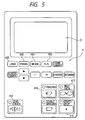
- Fig. 5 is a diagram showing the outer appearance of the display section 3 and the input section 4, which are formed into an integral unit.
- the input section 4 includes various setting switches such as a lens switch 402 for distinguishing either of plastics and glass as the constituent material of the lens to be processed, a frame switch 403 for distinguishing between resins and metals as the constituent material of the frame, a mode switch 404 for selecting the mode of lens processing to be performed (whether it is tapered edge (bevel) processing or plane processing), a R/L switch 405 for determining whether the lens to be processed is for use on the right eye or the left eye, a START/STOP switch 411 for starting or stopping the lens processing operation, a switch 413 for opening or closing the lens chucks, a tracing switch 416 for giving directions on the eyeglass frame and template tracing, and a next-data switch 417 for transferring the data measured with the eyeglass frame and template configuration measurement device 2.
- a lens switch 402 for distinguishing either of plastics and glass as the constituent
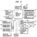
- FIG. 6 shows the essential part of the block diagram of the electronic control system for the eyeglass lens grinding machine of the invention.
- a main arithmetic control circuit 100 which is typically formed of a microprocessor and controlled by a sequence program stored in a main program memory 101.
- the main arithmetic control circuit 100 can exchange data with IC cards, eye examination devices and so forth via a serial communication port 102.
- the main arithmetic control circuit 100 also performs data exchange and communication with the eyeglass frame and template configuration measurement device 2. Data on the eyeglass frame configuration are stored in a data memory 103.
- the display section 3, the input section 4 and the lens configuration measuring device 5 are connected to the main arithmetic control circuit 100. Signals of the results of measurement as detected with the lens configuration measuring device 5 are processed arithmetically in the main arithmetic control circuit 100 and the resulting data for lens measurements are stored in the data memory 103.
- the carriage moving motor 714, as well as the pulse motors 728 and 721 are connected to the main arithmetic control circuit 100 via a pulse motor driver 110 and a pulse generator 111.
- the pulse generator 111 receives commands from the main arithmetic control circuit 100 and determines how may pulses are to be supplied at what frequency in Hz to the respective pulse motors to control their operation.
- Voltage signals from the photosensor 602 are processed with a signal processor circuit 604 and fed into the main arithmetic control circuit 100.
- the signal processor circuit 604 comprises an amplifier 610, a comparator 611 and a variable resistor 612.
- the voltage signal produced from the photosensor 602 is amplified by the amplifier 610 and fed into the comparator 611, which outputs a strobe signal when the signal from the photosensor 2 reaches the level of a voltage signal supplied from the variable resistor 612.
- the output strobe signal is a detection signal for the rotation of the abrasive wheels, which is fed into the main arithmetic control circuit 100.
- the machine performs arithmetic operations for correction in processing (i.e., the correction of the diameter of abrasive wheels) (see, for example, U.S. patent 5,347,762) so as to obtain data for lens processing and on the basis of this data, the machine will perform the following rough grinding operation.
- the abrasive wheel group 60 is rotated and, at the same time, the pulse motor 728 is run to vary the Y-axis.
- the amount by which the Y-axis is to be varied is determined on the basis of the data for lens processing and the main arithmetic control circuit 100 drives the pulse motor 728 such that the lens will be ground to have the desired profile (configuration).
- the lens is ground with the abrasive wheel onto which it is pressed under the resilient force of the spring 731.
- the main arithmetic control circuit 100 first supplies the pulse motor 728 with a Y-axis varying signal at the reference position for rotation and then drives the pulse motor 721 to rotate the lens through a small angle.
- the main arithmetic control circuit 100 supplies the pulse motor 728 with an operation signal which varies the Y-axis on the basis of the data for lens processing.
- the main arithmetic control circuit 100 controls the movement of the Y-axis continually in succession until the lens is ground to have the intended profile (configuration).
- the main arithmetic control circuit 100 monitors the number of rotations of the abrasive wheels, or the rotational speed of the abrasive wheels as detected by the combination of the photosensor 602 and the signal processor circuit 604.
- the number of rotations of the abrasive wheels is detected by counting the number per unit time of strobe signals that are produced from the comparator 611. As the amount of the lens to be ground increases, an increased grinding load is exerted on the abrasive wheels, and thus the number of their rotations decreases.
- the rotational speed of the abrasive wheels drops below the normal number of rotations (i.e., the reference number of rotations) to a specified level (say, 70% of the reference number of rotations)
- the rotation of the abrasive wheels by means of the pulse motor 721 is brought to a temporary stop (or, alternatively, the rotational speed of the lens is reduced).
- the lens stops rotating less of the lens is ground and the grinding load decreases, whereupon the number of rotations of the abrasive wheels per unit time starts to restore.
- the lens restarts to rotate for processing.
- the movement of the Y-axis may be controlled by the pulse motor 728 to inactivate the urging force of the spring 731 and this is effective in causing the rotation of the abrasive wheels to revert to the threshold level for the start of lens rotation more quickly.
- the number of rotations of the abrasive wheels is monitored (alternatively, the grinding load may be monitored directly) so as to control the rotation of the lens in a variable manner, thereby ensuring that the grinding load on the abrasive wheels will increase so much as to cause the abrasive wheels to stop rotating during lens processing.
- excessive flow of abnormal currents through the AC motor 65 can be effectively prevented to protect the machine against thermal damage and other troubles while ensuring that no undesirable burden will be imposed on the power supply equipment.
- the abrasive wheels (or the rotational shaft 61a) are constantly checked for the state of their rotation to thereby ensure the detection of any abnormal rotations of the abrasive wheels which will occur in certain cases such as where there occurs something abnormal in the belt 64 transmitting the rotation of the AC motor 65 or where vapor condensation on the machine or other phenomena cause a slip between the pulley 63 and the belt 64.
- a STOP signal is issued to stop the rotational driving of the AC motor 65 and, at the same time, an ERROR or other suitable information to indicate the occurrence of something abnormal is displayed in the display section 3. This procedure not only prevents the machine from being damaged but also notifies the operator of the need to check it for any abnormal parts.
- the lens rotation and, hence, the amount of the lens to be ground is controlled on the basis of the information on the rotation of abrasives which has been obtained from the abrasive wheel rotation detecting section 600.
- the present invention allows the grinding capability of abrasive wheels to be effectively utilized to thereby accomplish efficient grinding operations.
Landscapes
- Engineering & Computer Science (AREA)
- Mechanical Engineering (AREA)
- Chemical & Material Sciences (AREA)
- Ceramic Engineering (AREA)
- Inorganic Chemistry (AREA)
- Grinding And Polishing Of Tertiary Curved Surfaces And Surfaces With Complex Shapes (AREA)
Description
- The present invention relates to an apparatus and a method for grinding the periphery of an eyeglass lens to fit into an eyeglass frame.
- An eyeglass lens grinding machine is known and this machine grinds a lens on the basis of the frame configuration data obtained by tracing (profiling) an eyeglass frame with a tracer. The machine has lens grinding abrasive wheels which are driven with a motor to rotate at high speed and a carriage which clamps the lens between rotating shafts and holds it rotatably. With the lens being revolved, the carriage is rotationally moved on the basis of the frame configuration data such that the distance between the axis of the lens rotating shaft and that of the abrasive wheel rotating shaft is adjusted to permit the grinding of the edge of the lens as it is brought in contact with the abrasive wheel. During the grinding operation, the carriage is rotationally moved such that the grinding pressure on the abrasive wheel is maintained constant by a spring force or the like whereas the required grinding load is exerted between the lens and the abrasive wheel by the rotation of both. The force to rotate the abrasive wheel is transmitted from the associated motor via a belt.
- A problem with the conventional eyeglass lens grinding machine is that if with a view to enhancing the grinding efficiency, a high-performance abrasive wheel having great cutting power is employed or a higher rotational speed is adopted, the rotational load increases so much that the abrasive wheel will occasionally stop revolving. If the abrasive wheel stops rotating, an abnormal electric current will flow through the motor to increase the chance of the occurrence of thermal damage or other troubles. In addition, the increased rotational load has often affected the precision of lens processing. To deal with this situation, it has been necessary to perform the intended operation with the rotational speeds of the lens and the abrasive wheel being appropriately set by taking into account the highest grinding load that will be exerted during the processing operation; however, this eventually results in a failure to utilize the potential grinding capabilities of the above-described approaches to the fullest extent.
- EP-044 49 02 discloses a lens edging system which is numerically controlled by a computer to determine the rotation and the displacement of a lens work piece with respect to an edging tool in accordance with a lens shape stored in a memory. Especially it is disclosed a technology for an edging process in which optimal values for parameters of the abrasive wheel rotational speed, the lens rotation speed, the supply speed in the lens axis direction and the grinding pressure at each N. are determined through learning executed by a try-and-error fashion. These determined values are stored afterwards.
- The present invention has been accomplished under these circumstances and has as an object providing an eyeglass lens grinding machine which utilizes the grinding capability of the abrasive wheel to such an extent that the intended grinding operation can be performed with high efficiency.
- Another object of the invention is to provide a method capable of such satisfactory grinding operation.
- The stated objects of the invention can be attained by the following.
- According to the invention the object is solved by the features of
claim 1 and 7. The subclaims contain further preferred developments of the invention. - In the accompanying drawings:
- Fig. 1 is a perspective view showing the general layout of the eyeglass lens grinding machine of the invention;
- Fig. 2 is a cross-sectional view of the carriage in the grinding machine;
- Fig. 3 is a diagram showing a drive mechanism for the carriage, as viewed in the direction of arrow A in Fig. 1;
- Figs. 4(a) and 4(b) illustrate the abrasive wheel rotation detecting section of the grinding machine;
- Fig. 5 is a diagram showing the outer appearance of the display and input sections of the grinding machine;
- Fig. 6 shows the essential part of a block diagram of the electronic control system for the grinding machine; and
- Fig. 7 shows a specific configuration of a signal processor circuit for use in detecting the rotation of abrasive wheels.
-
- An embodiment of the invention will now be described in detail with reference to the accompanying drawings.
- Fig. 1 is a perspective view showing the general layout of the eyeglass lens grinding machine of the invention. The
reference numeral 1 designates a machine base, on which the components of the machine are arranged. Thenumeral 2 designates an eyeglass frame and template configuration measuring device, which is incorporated in the upper section of the grinding machine to obtain three-dimensional configuration data on the geometries of the eyeglass frame and the template (see, for example, commonly assigned U.S. patent 5,333,412). Arranged in front of themeasuring device 2 are adisplay section 3 which displays the results of measurements, arithmetic operations, etc. in the form of either characters or graphics, and aninput section 4 for entering data or feeding commands to the machine. Provided in the front section of the machine is a lens configuration measuringdevice 5 for measuring the imaginary edge thickness, etc. of an unprocessed lens (see, for example, U.S. patent 5,347,762). - The
reference numeral 6 designates a lens grinding section, where anabrasive wheel group 60 made up of a roughabrasive wheel 60a for use on glass lenses, a roughabrasive wheel 60b for use on plastic lenses and a finishingabrasive wheel 60c for tapered edge (bevel) and plane processing operations is mounted on the rotatingshaft 61a of aspindle unit 61, which is attached to themachine base 1 by means offixing bands 62. Apulley 63 is attached to an end of the abrasive wheel rotatingshaft 61a of thespindle unit 61. Thepulley 63 is linked to apulley 66 via abelt 64, with thepulley 66 being attached to the rotational shaft of anAC motor 65. Accordingly, the rotation of themotor 65 causes theabrasive wheel group 60 to rotate. Thespindle unit 61 is also provided with an abrasive wheelrotation detecting section 600 which detects the rotation of the abrasive wheel rotatingshaft 61a. Shown by 7 is a carriage section and 700 is a carriage. - The construction of the carriage section will now be described with reference to Figs. 1 to 3. Fig. 2 is a cross-sectional view of the carriage, and Fig. 3 is a diagram showing a drive mechanism for the carriage, as viewed in the direction of arrow A in Fig. 1. The
carriage 700 is so adapted that it not only chucks the workpiece lens LE (i.e. the lens to be processed) for rotation but also adjusts the distance of the lens LE with respect to the abrasive wheel rotatingshaft 61a and its position in the direction oflens rotating shafts shaft 61a and each of thelens rotating shafts - A
shaft 701 is secured on thebase 1 and acarriage shaft 702 is rotatably and slidably supported on theshaft 701; thecarriage 700 is pivotally supported on thecarriage shaft 702.Lens rotating shafts carriage 700, extending parallel to theshaft 701 and with the distance therefrom being unchanged. Thelens rotating shaft 704b is rotatably supported in arack 705, which is movable in the axial direction by means of apinion 707 fixed on the rotational shaft of amotor 706; as a result, thelens rotating shaft 704b is moved axially such that it is opened or closed with respect to the otherlens rotating shaft 704a, thereby holding the lens LE in position. - A
drive plate 716 is securely fixed at the left end of thecarriage 700 and arotational shaft 717 is rotatably provided on thedrive plate 716, extending parallel to theshaft 701. Agear 720 is provided at the right end of therotational shaft 717 to mesh with a gear attached on apulse motor 721, which is secured on ablock 722 which is rotatably attached to thedrive plate 716 in such a way that it is coaxial with therotational shaft 717. When thepulse motor 721 rotates, apulley 718 attached at the left end of therotational shaft 717 rotates and the resulting rotation is transmitted to theshaft 702 via atiming belt 719 and apulley 703a. The rotation of theshaft 702 in turn is transmitted to the lens chuckingshafts pulleys shaft 702,pulleys lens rotating shafts timing belts pulse motor 721 causes the lens chuckingshafts - An
intermediate plate 710 is rotatably secured at the left end of thecarriage 700. Theintermediate plate 710 has arack 713 which meshes with apinion 715 attached to the rotational shaft of acarriage moving motor 714 secured to thebase 1, extending parallel to theshaft 701. Twocam followers 711 are provided on the side of theintermediate plate 710 which is away from the operator such that they clamp aguide shaft 712 secured on thebase 1, extending parallel to theshaft 701. With this arrangement, themotor 714 is capable of moving thecarriage 700 in the axial direction of the shaft 701 (in the direction of X-axis). - The Y-axis of the
carriage 700 is changed by apulse motor 728, which is secured to ablock 722 in such a way that around rack 725 meshes with apinion 730 secured to therotational shaft 729 of thepulse motor 728. Theround rack 725 extends parallel to the shortest line segment connecting the axis of therotational shaft 717 and that of theshaft 723 secured to theintermediate plate 710; in addition, theround rack 725 is held to be slidable with a certain degree of freedom between acorrection block 724 which is rotatably fixed on theshaft 723 and theblock 722. Astopper 726 is fixed on theround rack 725 so that it is capable of sliding only downward from the position of contact with thecorrection block 724. With this arrangement, the axis-to-axis distance r' between therotational shaft 717 and theshaft 723 can be controlled in accordance with the rotation of thepulse motor 728 and it is also possible to control the axis-to-axis distance r between the abrasive wheelrotating shaft 61a and each of thelens chucking shafts - A hook of a
spring 731 is in engagement with thedrive plate 716 secured to thecarriage 700 and awire 732 is in engagement with a hook at the other end of thespring 731. A drum is attached to the rotational shaft of amotor 733 secured on theintermediate plate 710 such that the resilient force of thespring 731 can be adjusted by winding up thewire 732. Thecarriage 700 is pulled by thespring 731 toward the abrasive wheels such that it continues to move in the direction of Y-axis until thestopper 726 contacts thecorrection block 724. However, during the lens processing, thecarriage 700 is pushed up by the reaction of the abrasive wheels so that thestopper 726 will not contact thecorrection block 724 until after the end of the necessary processing in the direction of Y-axis which is controlled by the rotation of thepulse motor 728. The contact of thestopper 726 with thecorrection block 724 is checked by asensor 727 on theintermediate plate 710 so as to detect the end of lens processing. - Figs. 4(a) and 4(b) illustrate the abrasive wheel
rotation detecting section 600. Thereference numeral 63a designates a shaft mounting portion which is part of thepulley 63 and which has ahole 63b formed therein (as thehole 63b, one for use in securing therotating shaft 61a to thepulley 63 by means of a fastening screw may be used). Indicated by 601 and 602 are an LED and a photosensor, respectively, and they are attached to thespindle unit 61 by means of securing members (not shown) in such a way that their optical axes cross each other on the surface of theshaft mounting portion 63a. Light emitted from theLED 601 is reflected from the surface of theshaft mounting portion 63a to be directed toward thephotosensor 602. When thepulley 63 is rotated by theAC motor 65 to cause thehole 63b to pass across the optical axis of the light received by thephotosensor 602, there occurs a sufficient change in the amount of reflected light for the photosensor 602 to detect the state of rotation of therotating shaft 61a (i.e., the state of rotation of the abrasive wheel group 60). If desired, a reflecting member may be wrapped around theshaft mounting portion 63a in order to enhance the efficiency of reflected light or thehole 63b may be replaced by a mark or the like; these modifications will provide greater ease in detection. - The abrasive wheel
rotation detecting section 600 may alternatively be designed to detect the rotation of an end face of therotating shaft 61a; it may also be adapted to detect the rotation of the abrasive wheels per se. Besides the optical method just described above, magnetic and various other means may be employed to detect the amount of rotation of the abrasive wheels. - Fig. 5 is a diagram showing the outer appearance of the
display section 3 and theinput section 4, which are formed into an integral unit. Theinput section 4 includes various setting switches such as alens switch 402 for distinguishing either of plastics and glass as the constituent material of the lens to be processed, aframe switch 403 for distinguishing between resins and metals as the constituent material of the frame, amode switch 404 for selecting the mode of lens processing to be performed (whether it is tapered edge (bevel) processing or plane processing), a R/L switch 405 for determining whether the lens to be processed is for use on the right eye or the left eye, a START/STOP switch 411 for starting or stopping the lens processing operation, aswitch 413 for opening or closing the lens chucks, atracing switch 416 for giving directions on the eyeglass frame and template tracing, and a next-data switch 417 for transferring the data measured with the eyeglass frame and templateconfiguration measurement device 2. - Fig. 6 shows the essential part of the block diagram of the electronic control system for the eyeglass lens grinding machine of the invention. A main
arithmetic control circuit 100 which is typically formed of a microprocessor and controlled by a sequence program stored in amain program memory 101. The mainarithmetic control circuit 100 can exchange data with IC cards, eye examination devices and so forth via aserial communication port 102. The mainarithmetic control circuit 100 also performs data exchange and communication with the eyeglass frame and templateconfiguration measurement device 2. Data on the eyeglass frame configuration are stored in adata memory 103. - The
display section 3, theinput section 4 and the lensconfiguration measuring device 5 are connected to the mainarithmetic control circuit 100. Signals of the results of measurement as detected with the lensconfiguration measuring device 5 are processed arithmetically in the mainarithmetic control circuit 100 and the resulting data for lens measurements are stored in thedata memory 103. Thecarriage moving motor 714, as well as thepulse motors arithmetic control circuit 100 via apulse motor driver 110 and apulse generator 111. Thepulse generator 111 receives commands from the mainarithmetic control circuit 100 and determines how may pulses are to be supplied at what frequency in Hz to the respective pulse motors to control their operation. - Voltage signals from the
photosensor 602 are processed with asignal processor circuit 604 and fed into the mainarithmetic control circuit 100. As shown specifically in Fig. 7, thesignal processor circuit 604 comprises anamplifier 610, acomparator 611 and a variable resistor 612. The voltage signal produced from thephotosensor 602 is amplified by theamplifier 610 and fed into thecomparator 611, which outputs a strobe signal when the signal from thephotosensor 2 reaches the level of a voltage signal supplied from the variable resistor 612. The output strobe signal is a detection signal for the rotation of the abrasive wheels, which is fed into the mainarithmetic control circuit 100. - We now describe the operation of the eyeglass lens grinding machine of the invention, chiefly with respect to a rough grinding mode. On the basis of the data for frame configuration measured with the eyeglass frame and template
configuration measuring device 2, the machine performs arithmetic operations for correction in processing (i.e., the correction of the diameter of abrasive wheels) (see, for example, U.S. patent 5,347,762) so as to obtain data for lens processing and on the basis of this data, the machine will perform the following rough grinding operation. - First, the
abrasive wheel group 60 is rotated and, at the same time, thepulse motor 728 is run to vary the Y-axis. The amount by which the Y-axis is to be varied is determined on the basis of the data for lens processing and the mainarithmetic control circuit 100 drives thepulse motor 728 such that the lens will be ground to have the desired profile (configuration). The lens is ground with the abrasive wheel onto which it is pressed under the resilient force of thespring 731. The mainarithmetic control circuit 100 first supplies thepulse motor 728 with a Y-axis varying signal at the reference position for rotation and then drives thepulse motor 721 to rotate the lens through a small angle. Simultaneously and in synchronism with this action, the mainarithmetic control circuit 100 supplies thepulse motor 728 with an operation signal which varies the Y-axis on the basis of the data for lens processing. Thus, by rotating the lens through small angles on the basis of the data for lens processing, the mainarithmetic control circuit 100 controls the movement of the Y-axis continually in succession until the lens is ground to have the intended profile (configuration). - Throughout the lens processing operation described above, the main
arithmetic control circuit 100 monitors the number of rotations of the abrasive wheels, or the rotational speed of the abrasive wheels as detected by the combination of thephotosensor 602 and thesignal processor circuit 604. The number of rotations of the abrasive wheels is detected by counting the number per unit time of strobe signals that are produced from thecomparator 611. As the amount of the lens to be ground increases, an increased grinding load is exerted on the abrasive wheels, and thus the number of their rotations decreases. If the number of their rotations per unit time (i.e., the rotational speed of the abrasive wheels) drops below the normal number of rotations (i.e., the reference number of rotations) to a specified level (say, 70% of the reference number of rotations), the rotation of the abrasive wheels by means of thepulse motor 721 is brought to a temporary stop (or, alternatively, the rotational speed of the lens is reduced). When the lens stops rotating, less of the lens is ground and the grinding load decreases, whereupon the number of rotations of the abrasive wheels per unit time starts to restore. When the number of rotations of the abrasive wheels has restored to the threshold level for the start of lens rotation, the lens restarts to rotate for processing. - If desired, on the moment the lens stops rotating, the movement of the Y-axis may be controlled by the
pulse motor 728 to inactivate the urging force of thespring 731 and this is effective in causing the rotation of the abrasive wheels to revert to the threshold level for the start of lens rotation more quickly. - Thus, in accordance with the invention, the number of rotations of the abrasive wheels is monitored (alternatively, the grinding load may be monitored directly) so as to control the rotation of the lens in a variable manner, thereby ensuring that the grinding load on the abrasive wheels will increase so much as to cause the abrasive wheels to stop rotating during lens processing. As a result, excessive flow of abnormal currents through the
AC motor 65 can be effectively prevented to protect the machine against thermal damage and other troubles while ensuring that no undesirable burden will be imposed on the power supply equipment. In addition, the abrasive wheels (or therotational shaft 61a) are constantly checked for the state of their rotation to thereby ensure the detection of any abnormal rotations of the abrasive wheels which will occur in certain cases such as where there occurs something abnormal in thebelt 64 transmitting the rotation of theAC motor 65 or where vapor condensation on the machine or other phenomena cause a slip between thepulley 63 and thebelt 64. If, after the lens stops rotating, the number of rotations of the abrasive wheels does not return to the threshold level for the start of lens rotation upon the lapse of a specified time period, a STOP signal is issued to stop the rotational driving of theAC motor 65 and, at the same time, an ERROR or other suitable information to indicate the occurrence of something abnormal is displayed in thedisplay section 3. This procedure not only prevents the machine from being damaged but also notifies the operator of the need to check it for any abnormal parts. - The above-described monitoring of the state of rotation of the abrasive wheels, as combined with the control of lens rotation offers the added advantage that the lens can be ground in amounts that have a good balance with the grinding load and, hence, even if high-performance abrasive wheels having great grinding power or if the rotational speed of the
AC motor 65 is increased, these approaches can be effectively utilized to achieve results that would be obtained if their grinding capabilities were exploited to near-limit levels. As a result, the lens processing time can be shortened. - While the eyeglass lens grinding machine of the invention has been described above with particular reference to rough grinding, it should be noted that in finishing and other operations, the lens rotation and, hence, the amount of the lens to be ground is controlled on the basis of the information on the rotation of abrasives which has been obtained from the abrasive wheel
rotation detecting section 600. - As described on the foregoing pages, the present invention allows the grinding capability of abrasive wheels to be effectively utilized to thereby accomplish efficient grinding operations.
Claims (11)
- Eyeglass lens grinding machine comprising:characterised in thatlens rotating means (700) for holding and rotating a lens (LE) to be processed;abrasive wheel rotating means (6) for rotating an abrasive wheel (60a, 60b, 60c) for grinding the lens (LE) on its own axis;abrasive wheel's rotational state detecting means (600) for detecting a state of rotation of the abrasive wheel (60a, 60b, 60c) caused by said abrasive wheel rotating means (6); androtation control means (100)the rotation control means (100) variably changes rotation of the lens caused by said lens rotating means (700) on the basis of the result detected by said abrasive wheel's rotational state detecting means (600),wherein when the abrasive wheel's rotational state is lowered to be smaller than a first predetermined level, the rotation of the lens is stopped until the state is recovered to be not smaller than a second predetermined level.
- Eyeglass lens grinding machine according to claim 1 wherein said abrasive wheel's rotational state detecting means has photodetector means (601, 602) for projecting light onto the rotating abrasive wheel or its shaft (63a) and for detecting reflected light therefrom.
- Eyeglass lens grinding machine according to claim 1 or 2, wherein if the state is not recovered to be not smaller than the second predetermined level even after a predetermined time period is elapsed from the stop of the rotation of the lens, a rotation stop signal for the abrasive wheel is generated.
- Eyeglass lens grinding machine according to one of claims 1 to 3, wherein said abrasive wheel's rotational state detecting means (600) includes load detecting means for detecting a grinding load, and wherein said rotation control means (100) includes:stop command means for issuing a command to stop the rotation of the lens if the load detected by said load detecting means exceeds a first predetermined reference value; andrestart command means for issuing a command to restart the rotation of the lens if the load is less than a second predetermined reference value.
- Eyeglass lens grinding machine according to one of claims 1 to 4, wherein said abrasive wheel's rotational state detecting means (600) includes rotational speed detecting means for detecting the rotational speed of the abrasive wheel or its shaft per unit time, and wherein said rotation control means (100) includes:stop command means for issuing a command to stop the rotation of the lens if the rotational speed of the abrasive wheel has become lower than a first predetermined rotational speed; andrestart command means for issuing a command to restart the rotation of the lens if the rotational speed of the abrasive wheel has become higher than a second predetermined rotational speed.
- Eyeglass lens grinding machine according to one of claims 1 to 5, wherein said abrasive wheel's rotational state detecting means (600) includes the number of rotations detecting means for detecting the number of rotations of the abrasive wheel or its shaft per unit time, and wherein said rotation control means (100) includes:stop command means for issuing a command to stop the rotation of the lens if the number of rotations of the abrasive wheel has become lower than a first predetermined number of rotations; andrestart command means for issuing a command to restart the rotation of the lens if the number of rotations of the abrasive wheel has become higher than a second predetermined number of rotations.
- Method for grinding eyeglass lenses, comprising steps of:1. holding and rotating a lens (LE) to be processed;2. rotating an abrasive wheel (60a, 60b, 60c) for grinding the lens (LE) its own axis;3. detecting a state of rotation of the abrasive wheel (60a, 60b, 60c); characterised by4. variably controlling the rotation of the lens (LE) on the basis of the detected state of rotation of the abrasive wheel;
wherein when abrasive wheel's rotational state is lowered to be smaller than a first predetermined level, the rotation of the lens is stopped first until the state is recovered to be not smaller than a second predetermined level. - Method for grinding eyeglass lenses according to claim 7, wherein the step 3. includes the step of projecting light onto the rotating abrasive wheel or its shaft (63a), and detecting reflected light therefrom.
- Method for grinding eyeglass lens according to claim 7 or 8, wherein the step 4. includes:stopping the rotation of the lens if the detected state of rotation of the abrasive wheel is lowered to be smaller than the first predetermined level; andrestarting the rotation of the lens if the detected state of rotation of the abrasive wheel is recovered to be not smaller than the second predetermined level.
- Method for grinding eyeglass lens according to one of claims 7 to 9 further comprising step of:5. generating a rotation stop signal for the abrasive wheel if the state is not recovered to be not smaller than the second predetermined level even after a predetermined time period is elapsed from the stop of the rotation of the lens.
- Method for grinding eyeglass lens according to one of claims 7 to 10, wherein the state of rotation of the abrasive wheel is detected as a grinding load on the abrasive wheel, the number of rotation or the rotational speed of the abrasive wheel or its shaft (63a) per unit time.
Applications Claiming Priority (3)
| Application Number | Priority Date | Filing Date | Title |
|---|---|---|---|
| JP307182/96 | 1996-10-31 | ||
| JP8307182A JPH10138108A (en) | 1996-10-31 | 1996-10-31 | Equipment and method for grinding spectacles lens |
| JP30718296 | 1996-10-31 |
Publications (2)
| Publication Number | Publication Date |
|---|---|
| EP0839604A1 EP0839604A1 (en) | 1998-05-06 |
| EP0839604B1 true EP0839604B1 (en) | 2002-02-27 |
Family
ID=17966031
Family Applications (1)
| Application Number | Title | Priority Date | Filing Date |
|---|---|---|---|
| EP97118973A Expired - Lifetime EP0839604B1 (en) | 1996-10-31 | 1997-10-30 | Apparatus and method for grinding eyeglass lenses |
Country Status (5)
| Country | Link |
|---|---|
| US (1) | US6123604A (en) |
| EP (1) | EP0839604B1 (en) |
| JP (1) | JPH10138108A (en) |
| DE (1) | DE69710672T2 (en) |
| ES (1) | ES2173365T3 (en) |
Cited By (1)
| Publication number | Priority date | Publication date | Assignee | Title |
|---|---|---|---|---|
| EP4342630A4 (en) * | 2021-05-17 | 2025-07-09 | Nidek Kk | CONDITION MANAGEMENT PROGRAM AND CONDITION MANAGEMENT PROCEDURES |
Families Citing this family (15)
| Publication number | Priority date | Publication date | Assignee | Title |
|---|---|---|---|---|
| JP2000015549A (en) | 1998-06-30 | 2000-01-18 | Nidek Co Ltd | Spectacle lens machining device |
| DE19914174A1 (en) | 1999-03-29 | 2000-10-12 | Wernicke & Co Gmbh | Method and device for shaping the peripheral edge of spectacle lenses |
| ATE390233T1 (en) * | 1999-08-06 | 2008-04-15 | Hoya Corp | EYEWEAR LENS PROCESSING METHOD AND APPARATUS |
| GB2357722B (en) * | 1999-10-27 | 2003-05-07 | Unova Uk Ltd | Workpiece grinding method which achieves a constant stock removal rate |
| JP3942802B2 (en) * | 2000-04-28 | 2007-07-11 | 株式会社ニデック | Eyeglass lens processing equipment |
| JP4288012B2 (en) | 2001-01-05 | 2009-07-01 | 株式会社ニデック | Eyeglass lens processing equipment |
| JP2003340698A (en) | 2002-05-30 | 2003-12-02 | Hoya Corp | Lens machining device and lens machining method |
| EP1445065A1 (en) * | 2003-02-05 | 2004-08-11 | Nidek Co., Ltd. | Eyeglass lens processing apparatus |
| US7090559B2 (en) * | 2003-11-19 | 2006-08-15 | Ait Industries Co. | Ophthalmic lens manufacturing system |
| DE102005007523A1 (en) * | 2005-02-17 | 2006-08-24 | Weco Optik Gmbh | Spectacle lens edging machine |
| JP4290673B2 (en) * | 2005-04-28 | 2009-07-08 | 株式会社ニデック | Glasses lens peripheral processing method |
| EP2543476B1 (en) * | 2011-07-04 | 2014-03-05 | Automation & Robotics | Apparatus and method for clamping and handling ophthalmic lenses |
| JP5899978B2 (en) * | 2012-02-03 | 2016-04-06 | 株式会社ニデック | Eyeglass lens processing equipment |
| CN111390698B (en) * | 2020-06-03 | 2020-09-01 | 宁波丞达精机有限公司 | Optical lens edging device and edging method |
| JP7767930B2 (en) * | 2022-01-06 | 2025-11-12 | 株式会社ニデック | Eyeglass lens processing device and eyeglass lens processing control program |
Family Cites Families (15)
| Publication number | Priority date | Publication date | Assignee | Title |
|---|---|---|---|---|
| IE67140B1 (en) * | 1990-02-27 | 1996-03-06 | Bausch & Lomb | Lens edging system |
| JP2925685B2 (en) * | 1990-08-02 | 1999-07-28 | 株式会社ニデック | Frame shape measuring device |
| US5333412A (en) * | 1990-08-09 | 1994-08-02 | Nidek Co., Ltd. | Apparatus for and method of obtaining processing information for fitting lenses in eyeglasses frame and eyeglasses grinding machine |
| JP2907974B2 (en) * | 1990-08-28 | 1999-06-21 | 株式会社ニデック | Eyeglass frame tracing device |
| DE69205786T2 (en) * | 1991-08-21 | 1996-03-28 | Tokyo Seimitsu Co Ltd | Sheet position detection device. |
| FR2682628B1 (en) * | 1991-10-21 | 1996-01-05 | Buchmann Optical Eng | IMPROVEMENTS IN GRINDING AND BEVELING MACHINES FOR OPHTHALMIC LENSES. |
| JP3011526B2 (en) * | 1992-02-04 | 2000-02-21 | 株式会社ニデック | Lens peripheral processing machine and lens peripheral processing method |
| FR2697769B1 (en) * | 1992-11-10 | 1995-01-13 | Buchmann Optical Eng | Automatic machine for grinding and beveling ophthalmic lenses. |
| DE4320934C2 (en) * | 1993-06-24 | 1995-04-20 | Wernicke & Co Gmbh | Spectacle lens edge grinding machine |
| JPH0744440A (en) * | 1993-08-04 | 1995-02-14 | Nec Corp | Data save device |
| JP3467807B2 (en) * | 1993-09-30 | 2003-11-17 | 豊田工機株式会社 | Grinding equipment |
| DE4414784C2 (en) * | 1994-04-28 | 1996-07-18 | Wernicke & Co Gmbh | System for grinding the peripheral edge and / or an optical surface of spectacle lenses |
| JPH08267347A (en) * | 1995-03-31 | 1996-10-15 | Shin Etsu Handotai Co Ltd | Mirror surface polishing method of wafer chamfer with orientation flat |
| DE19527222C2 (en) * | 1995-07-26 | 1997-09-04 | Wernicke & Co Gmbh | System for grinding at least the peripheral edge of spectacle lenses and method for mathematically taking into account the position of a spectacle lens blank held on a holding head of the system |
| DE19616536C2 (en) * | 1996-04-25 | 2000-01-27 | Wernicke & Co Gmbh | Process and eyeglass lens grinding machine for shaping the peripheral edge of eyeglass lenses and possibly for subsequent facet grinding |
-
1996
- 1996-10-31 JP JP8307182A patent/JPH10138108A/en active Pending
-
1997
- 1997-10-30 DE DE69710672T patent/DE69710672T2/en not_active Expired - Lifetime
- 1997-10-30 ES ES97118973T patent/ES2173365T3/en not_active Expired - Lifetime
- 1997-10-30 EP EP97118973A patent/EP0839604B1/en not_active Expired - Lifetime
- 1997-10-31 US US08/961,945 patent/US6123604A/en not_active Expired - Lifetime
Cited By (1)
| Publication number | Priority date | Publication date | Assignee | Title |
|---|---|---|---|---|
| EP4342630A4 (en) * | 2021-05-17 | 2025-07-09 | Nidek Kk | CONDITION MANAGEMENT PROGRAM AND CONDITION MANAGEMENT PROCEDURES |
Also Published As
| Publication number | Publication date |
|---|---|
| ES2173365T3 (en) | 2002-10-16 |
| US6123604A (en) | 2000-09-26 |
| EP0839604A1 (en) | 1998-05-06 |
| DE69710672D1 (en) | 2002-04-04 |
| JPH10138108A (en) | 1998-05-26 |
| DE69710672T2 (en) | 2002-08-01 |
Similar Documents
| Publication | Publication Date | Title |
|---|---|---|
| US6123604A (en) | Apparatus and method for grinding eyeglass lenses | |
| US5347762A (en) | Lens periphery processing apparatus, method for obtaining processing data, and lens periphery processing method | |
| JP3730410B2 (en) | Eyeglass lens processing equipment | |
| JP3730409B2 (en) | Eyeglass lens processing equipment | |
| EP1155775B1 (en) | Eyeglass lens processing apparatus | |
| US6089957A (en) | Method of grinding eyeglass len, and eyeglass lens grinding apparatus | |
| EP0489856A4 (en) | Method and apparatus for edging an optical lens | |
| EP0839609A1 (en) | Apparatus and method for grinding eyeglass lenses | |
| US20040192170A1 (en) | Eyeglass lens processing apparatus | |
| US6261150B1 (en) | Eyeglass lens grinding apparatus | |
| EP1034884A2 (en) | Device for the display of engravement shape of eyeglass lens and method and apparatus for machining lens peripheral edge using the display device | |
| US5993294A (en) | Method and spectacle lens grinding machine for shape grinding the circumferential edge of spectacle lenses and optionally for subsequently grinding a facet | |
| US7169013B2 (en) | Eyeglass lens processing apparatus | |
| US4820092A (en) | Touch sensing method and apparatus | |
| JP4431413B2 (en) | Eyeglass lens processing equipment | |
| EP0868971A2 (en) | Apparatus for grinding eyeglass lens | |
| EP1792688B1 (en) | Eyeglass lens processing apparatus | |
| JP3681211B2 (en) | Eyeglass lens edging device | |
| JP2513342B2 (en) | Retraction grinding method and grinding device in grinding force control grinding | |
| JP3893081B2 (en) | Eyeglass lens processing equipment | |
| JP4392140B2 (en) | Lens grinding method and lens grinding device | |
| JP4047184B2 (en) | Eyeglass lens processing equipment | |
| JPH0557608A (en) | Grinding machine dressing device | |
| JPH07116948A (en) | Jade machine | |
| JPH07108456A (en) | Grinding device |
Legal Events
| Date | Code | Title | Description |
|---|---|---|---|
| PUAI | Public reference made under article 153(3) epc to a published international application that has entered the european phase |
Free format text: ORIGINAL CODE: 0009012 |
|
| AK | Designated contracting states |
Kind code of ref document: A1 Designated state(s): DE ES FR GB |
|
| AX | Request for extension of the european patent |
Free format text: AL;LT;LV;RO;SI |
|
| 17P | Request for examination filed |
Effective date: 19981005 |
|
| AKX | Designation fees paid |
Free format text: DE FR GB |
|
| RBV | Designated contracting states (corrected) |
Designated state(s): DE FR GB |
|
| RBV | Designated contracting states (corrected) |
Designated state(s): DE ES FR GB |
|
| 17Q | First examination report despatched |
Effective date: 20000505 |
|
| GRAG | Despatch of communication of intention to grant |
Free format text: ORIGINAL CODE: EPIDOS AGRA |
|
| GRAH | Despatch of communication of intention to grant a patent |
Free format text: ORIGINAL CODE: EPIDOS IGRA |
|
| GRAG | Despatch of communication of intention to grant |
Free format text: ORIGINAL CODE: EPIDOS AGRA |
|
| GRAH | Despatch of communication of intention to grant a patent |
Free format text: ORIGINAL CODE: EPIDOS IGRA |
|
| REG | Reference to a national code |
Ref country code: GB Ref legal event code: IF02 |
|
| GRAA | (expected) grant |
Free format text: ORIGINAL CODE: 0009210 |
|
| AK | Designated contracting states |
Kind code of ref document: B1 Designated state(s): DE ES FR GB |
|
| REF | Corresponds to: |
Ref document number: 69710672 Country of ref document: DE Date of ref document: 20020404 |
|
| ET | Fr: translation filed | ||
| REG | Reference to a national code |
Ref country code: ES Ref legal event code: FG2A Ref document number: 2173365 Country of ref document: ES Kind code of ref document: T3 |
|
| PLBE | No opposition filed within time limit |
Free format text: ORIGINAL CODE: 0009261 |
|
| STAA | Information on the status of an ep patent application or granted ep patent |
Free format text: STATUS: NO OPPOSITION FILED WITHIN TIME LIMIT |
|
| 26N | No opposition filed |
Effective date: 20021128 |
|
| PGFP | Annual fee paid to national office [announced via postgrant information from national office to epo] |
Ref country code: DE Payment date: 20121024 Year of fee payment: 16 |
|
| PGFP | Annual fee paid to national office [announced via postgrant information from national office to epo] |
Ref country code: ES Payment date: 20130911 Year of fee payment: 17 |
|
| PGFP | Annual fee paid to national office [announced via postgrant information from national office to epo] |
Ref country code: GB Payment date: 20131030 Year of fee payment: 17 Ref country code: FR Payment date: 20131009 Year of fee payment: 17 |
|
| REG | Reference to a national code |
Ref country code: DE Ref legal event code: R119 Ref document number: 69710672 Country of ref document: DE Effective date: 20140501 |
|
| PG25 | Lapsed in a contracting state [announced via postgrant information from national office to epo] |
Ref country code: DE Free format text: LAPSE BECAUSE OF NON-PAYMENT OF DUE FEES Effective date: 20140501 |
|
| GBPC | Gb: european patent ceased through non-payment of renewal fee |
Effective date: 20141030 |
|
| PG25 | Lapsed in a contracting state [announced via postgrant information from national office to epo] |
Ref country code: GB Free format text: LAPSE BECAUSE OF NON-PAYMENT OF DUE FEES Effective date: 20141030 |
|
| REG | Reference to a national code |
Ref country code: FR Ref legal event code: ST Effective date: 20150630 |
|
| PG25 | Lapsed in a contracting state [announced via postgrant information from national office to epo] |
Ref country code: FR Free format text: LAPSE BECAUSE OF NON-PAYMENT OF DUE FEES Effective date: 20141031 |
|
| REG | Reference to a national code |
Ref country code: ES Ref legal event code: FD2A Effective date: 20151126 |
|
| PG25 | Lapsed in a contracting state [announced via postgrant information from national office to epo] |
Ref country code: ES Free format text: LAPSE BECAUSE OF NON-PAYMENT OF DUE FEES Effective date: 20141031 |