EP0839274B1 - Fuel supply system - Google Patents
Fuel supply system Download PDFInfo
- Publication number
- EP0839274B1 EP0839274B1 EP96910287A EP96910287A EP0839274B1 EP 0839274 B1 EP0839274 B1 EP 0839274B1 EP 96910287 A EP96910287 A EP 96910287A EP 96910287 A EP96910287 A EP 96910287A EP 0839274 B1 EP0839274 B1 EP 0839274B1
- Authority
- EP
- European Patent Office
- Prior art keywords
- fuel
- tank
- pressure regulator
- hose
- regulator
- Prior art date
- Legal status (The legal status is an assumption and is not a legal conclusion. Google has not performed a legal analysis and makes no representation as to the accuracy of the status listed.)
- Expired - Lifetime
Links
- 239000000446 fuel Substances 0.000 title claims description 94
- 239000002828 fuel tank Substances 0.000 claims description 22
- 238000002485 combustion reaction Methods 0.000 claims description 4
- 238000002347 injection Methods 0.000 claims description 3
- 239000007924 injection Substances 0.000 claims description 3
- 238000003915 air pollution Methods 0.000 description 4
- 210000002445 nipple Anatomy 0.000 description 4
- 238000001816 cooling Methods 0.000 description 3
- 230000000694 effects Effects 0.000 description 2
- 239000003517 fume Substances 0.000 description 2
- 239000000203 mixture Substances 0.000 description 2
- 230000006835 compression Effects 0.000 description 1
- 238000007906 compression Methods 0.000 description 1
- 238000001704 evaporation Methods 0.000 description 1
- 230000008020 evaporation Effects 0.000 description 1
- 230000002349 favourable effect Effects 0.000 description 1
- 238000010438 heat treatment Methods 0.000 description 1
- 229930195733 hydrocarbon Natural products 0.000 description 1
- 150000002430 hydrocarbons Chemical class 0.000 description 1
- 238000007654 immersion Methods 0.000 description 1
- 239000011810 insulating material Substances 0.000 description 1
- 239000007788 liquid Substances 0.000 description 1
- 239000000463 material Substances 0.000 description 1
- 230000001902 propagating effect Effects 0.000 description 1
- 230000001105 regulatory effect Effects 0.000 description 1
- 238000007789 sealing Methods 0.000 description 1
- 239000000243 solution Substances 0.000 description 1
- 238000009423 ventilation Methods 0.000 description 1
Images


Classifications
-
- F—MECHANICAL ENGINEERING; LIGHTING; HEATING; WEAPONS; BLASTING
- F02—COMBUSTION ENGINES; HOT-GAS OR COMBUSTION-PRODUCT ENGINE PLANTS
- F02M—SUPPLYING COMBUSTION ENGINES IN GENERAL WITH COMBUSTIBLE MIXTURES OR CONSTITUENTS THEREOF
- F02M37/00—Apparatus or systems for feeding liquid fuel from storage containers to carburettors or fuel-injection apparatus; Arrangements for purifying liquid fuel specially adapted for, or arranged on, internal-combustion engines
- F02M37/0011—Constructional details; Manufacturing or assembly of elements of fuel systems; Materials therefor
- F02M37/0023—Valves in the fuel supply and return system
- F02M37/0029—Pressure regulator in the low pressure fuel system
-
- F—MECHANICAL ENGINEERING; LIGHTING; HEATING; WEAPONS; BLASTING
- F02—COMBUSTION ENGINES; HOT-GAS OR COMBUSTION-PRODUCT ENGINE PLANTS
- F02M—SUPPLYING COMBUSTION ENGINES IN GENERAL WITH COMBUSTIBLE MIXTURES OR CONSTITUENTS THEREOF
- F02M37/00—Apparatus or systems for feeding liquid fuel from storage containers to carburettors or fuel-injection apparatus; Arrangements for purifying liquid fuel specially adapted for, or arranged on, internal-combustion engines
- F02M37/0076—Details of the fuel feeding system related to the fuel tank
- F02M37/0082—Devices inside the fuel tank other than fuel pumps or filters
-
- F—MECHANICAL ENGINEERING; LIGHTING; HEATING; WEAPONS; BLASTING
- F02—COMBUSTION ENGINES; HOT-GAS OR COMBUSTION-PRODUCT ENGINE PLANTS
- F02M—SUPPLYING COMBUSTION ENGINES IN GENERAL WITH COMBUSTIBLE MIXTURES OR CONSTITUENTS THEREOF
- F02M37/00—Apparatus or systems for feeding liquid fuel from storage containers to carburettors or fuel-injection apparatus; Arrangements for purifying liquid fuel specially adapted for, or arranged on, internal-combustion engines
- F02M37/04—Feeding by means of driven pumps
- F02M37/08—Feeding by means of driven pumps electrically driven
- F02M37/10—Feeding by means of driven pumps electrically driven submerged in fuel, e.g. in reservoir
-
- F—MECHANICAL ENGINEERING; LIGHTING; HEATING; WEAPONS; BLASTING
- F02—COMBUSTION ENGINES; HOT-GAS OR COMBUSTION-PRODUCT ENGINE PLANTS
- F02M—SUPPLYING COMBUSTION ENGINES IN GENERAL WITH COMBUSTIBLE MIXTURES OR CONSTITUENTS THEREOF
- F02M37/00—Apparatus or systems for feeding liquid fuel from storage containers to carburettors or fuel-injection apparatus; Arrangements for purifying liquid fuel specially adapted for, or arranged on, internal-combustion engines
- F02M37/0047—Layout or arrangement of systems for feeding fuel
- F02M37/007—Layout or arrangement of systems for feeding fuel characterised by its use in vehicles, in stationary plants or in small engines, e.g. hand held tools
Definitions
- the subject invention refers to a fuel supply system for a combustion engine, which includes a fuel tank, suitably supplied with a fuel filter and a duct, for instance a fuel hose, which connects the fuel tank with a fuel supply unit, for instance a carburetor or a fuel injection system, and a pressure regulator is flexibly mounted to one side of the tank, suitably the upper side, and the pressure regulator is mounted to the end of a hose, which is mounted in the tank's wall, suitably at its upper side, and extends down into the inside of the tank, and a fuel filter is suitably mounted to the pressure regulator.
- a fuel supply system for a combustion engine which includes a fuel tank, suitably supplied with a fuel filter and a duct, for instance a fuel hose, which connects the fuel tank with a fuel supply unit, for instance a carburetor or a fuel injection system, and a pressure regulator is flexibly mounted to one side of the tank, suitably the upper side, and the pressure regulator is mounted to the
- a handheld working tool such as a chain saw
- a ventilation filter usually made of sintered material.
- the tool can be inclined without any significant fuel leakage, but the other problems, such as smell and air pollution, remain.
- a fuel system which comprises a pressure regulator connected to the fuel tank
- the regulator prevents fuel and fuel fumes from leaking out of the fuel tank when it is under overpressure.
- the regulator is mounted in such a way that it protrudes from the fuel tank and is in its entirety located above the fuel level. Due to this location the regulator is heated up by the heat from the adjacent cylinder and cannot significantly be cooled down by the fuel. This implies an increased risk for vapor bubbles being formed in the fuel and thus causing a so called vapor lock in the regulator.
- US 4,682,936 shows a fuel system with an immersed fuel pump with attached fuel filter and a pressure regulator located approximately midway of an output tube leaving the pump. The filter and the regulator are located and held at fixed positions in the fuel tank. If the tank would be tilted or overturned the filter and regulator could end up above the fuel level in the tank.
- the purpose of the subject invention is to substantially reduce the above out-lined problems by creating a fuel supply system that prevents or substantially reduces the possibility of any overpressure in the fuel tank propagating to the engine's fuel supply unit, at the same time as heat related problems to a great extent are avoided.
- a fuel supply system that prevents or substantially reduces the possibility of any overpressure in the fuel tank propagating to the engine's fuel supply unit, at the same time as heat related problems to a great extent are avoided.
- conditions are created for substantially reducing air pollution and smell caused by evaporation, with maintained satisfactory starting properties and reliability of operation.
- the fuel supply system in accordance with the invention is thus essentially characterized in that an air hose is arranged from the regulator's air connection and extends out through the tank's wall, so that the pressure regulator is only mounted to the hose and to the air hose, and as both hoses are mounted to one side of the tank the pressure regulator is mobile inside the tank .
- the pressure regulator's immersed location reduces its heating and improves its cooling, so that satisfactory starting properties and reliability of operation can be obtained.
- a closed, non-ventilated fuel tank can be used, and air pollution be avoided.
- the pressure regulator is mobile in the tank being only connected by hose/s to the tank. It therefore reaches the deepest part of the tank.
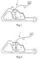
- FIG. 1 shows a fuel supply system that is not in accordance with the invention.
- the system's fuel tank is integrated with a part of a handle system for a chain saw.
- a pressure regulator is mounted mainly inside the fuel tank.
- FIG. 2 shows a fuel supply system in accordance with the invention.
- the system's pressure regulator and fuel filter hang down in the tank in a fuel duct and an air duct.
- Figure 3 shows a first embodiment of a pressure regulator, which is a part of the fuel supply system and can be used together with the invention if slightly altered as discussed below.
- Figure 4 shows a second embodiment of a pressure regulator, which is a part of the fuel supply system.
- Figure 5 shows a pressure regulator similar to the one in figure 3, but immersed in a cavity in the fuel tank. This arrangement is not in accordance with the invention.
- numeral reference 1 designates a fuel supply system that is not in accordance with the invention. It includes a fuel tank 2. A pressure regulator 6, 7 is mounted at its upper side, so that it protrudes down into the tank. This positioning is especially favorable in this case, but the regulator can naturally also be placed in other positions.
- a fuel duct 4, for instance a fuel hose 4 extends from the inside of the fuel tank to a fuel supply unit 5, for example a carburetor or a fuel injection system. In this case the duct consists of a first part 4', which extends from the pressure regulator 6, 7 into the inside of the tank. Its inlet is suitably supplied with a fuel filter 3.
- a fuel supply system for a chain saw i.e.
- the tank is turned in all positions during usage of the tool, except for straight upside down.
- the fuel intake by the fuel filter will hang down in the lower part of the tank or rest against a side wall, when the working tool is inclined.
- the first part 4' of the duct 4 can also be designed as a spiral hose, so that the hose's inlet with a possible fuel filter 3 is given an extra large mobility inside the tank. It can thereby rest against the tank's various walls without the hose being so long that it runs the risk of entangling itself.
- a second part 4" of the duct 4 extends from the pressure regulator 6, 7 to the fuel supply device 5.
- FIG. 2 shows a fuel supply system in accordance with the invention.
- the pressure regulator 6, 7 is mounted to the end of a hose 4, which is mounted in the wall of the tank and extends down into the inside of the tank.
- a fuel filter 3 is mounted to the pressure regulator and an air hose 8 is arranged from the regulator's air connection and extends out through the wall of the tank.
- the hose is mounted in the upper side of the tank, which usually is an advantage. Naturally, it can also be mounted on other sides of the tank.
- An advantage with this arrangement is that the pressure regulator's weight helps to bring down the fuel inlet to the deepest part of the tank. This is important, especially for a handheld working tool, which is used a lot.
- the two hoses 4 and 8 are suitably connected and designed as a so called spiral hose. It usually looks like an ordinary telephone wire.
- the fuel inlet is given an extra large mobility inside the tank, so that the inlet easily reaches the tank's deepest part, without an unnecessarily long hose having to be used. This could otherwise increase the risk of the hose entangling itself.
- FIG 3 shows a pressure regulator 6, which is especially suited to be used in combination with a fuel supply unit 5, which takes up fuel on its own, for instance a carburetor with a built-in pump. It is primarily intended for the figure 1 fuel supply system but can also be altered for the figure 2 fuel supply system, as discussed below.
- the regulator consists of an upper housing part 9 and a lower housing part 10.
- a diaphragm 11 is squeezed between the housing parts, air and liquid tight.
- the diaphragm 11 divides a cavity 12 inside the regulator into an upper part 12' and a lower part 12".
- the upper cavity part 12' is connected with a fuel inlet 13, which in this case is supplied with a fuel nipple 14 so that a fuel hose can be connected - in the embodiment in accordance with figure 1, hose 4'.
- a hose is not required, since the fuel inlet in this case exits directly in the fuel filter 3 inside the tank.
- a fuel duct 15 extends to the upper cavity part 12'.
- a valve body 16 is arranged at the mouth. The valve body is in its opposite end mounted to one of the ends of a lever 17, whose other end is mounted to the diaphragm 11. The lever 17 turns around a pivot 18 and a spring 19 loads the lever 17, so that the valve body 16 closes the fuel duct 15, at least when there is no suction effect at the fuel outlet 20.
- a fuel nipple 21 is arranged at the fuel outlet in order to connect a fuel hose, hose 4" in figure 1 and hose 4 in figure 2.
- the lower cavity part 12" is supplied with an air duct 22. This exits on the upper side of the regulator body, which is suitable in the embodiments in accordance with figures 1 and 2.
- the mouth can be supplied with a hose nipple, or a dirt cover.
- a mounting flange 23 extends around the upper housing part 9 and enables the pressure regulator to be fitted immersed in the tank 2.
- the tank 2 then has an opening or a hole in one side, which is big enough to bring the pressure regulator into the hole and for it to rest against flange 23, suitably with a sealing between the tank and the flange.
- One advantage with this design is that the regulator protrudes only marginally and is well protected inside the tank, at the same time as it easily can be replaced. However, the regulator can naturally also be fitted entirely on the inside of the tank. Two different alternative designs are shown with dash dotted lines. A higher located flange 23 can be seen at the top of the figure.
- the air duct 22 as well as the fuel duct including outlet 20 are extended, so that they reach the upper side of the regulator.
- the regulator is immersed deeper into the fuel and even the greater part of its upper side can be covered by fuel, so that the important cooling effect is enhanced.
- the fuel nipple 14 is located at approximately the same distance from the tank's corners, especially the lower ones. Owing to the immersion in the tank, the regulator is cooled effectively at the same time as it takes up little heat from the cylinder, and this can easily be enhanced by means of insulating material along its upper side.
- a check valve 30 is firmly mounted in the flange 23. This also applies to the alternative dash dotted solution, but is not shown there. It has an air inlet 31 and an outlet 32. A spring 33 presses a ball 34 against a tapered valve seat 35. Fumes and fuel cannot pass from the outlet 32 to the inlet 31. On the other hand, air can pass the opposite way and prevent underpressure from arising in the fuel tank.
- the air duct 22 brings in atmospheric pressure to the underside of the diaphragm 11.
- the compression spring 19 is tuned so that the valve body 16 keeps the fuel duct 15 closed up to approximately 200 kPa pressure in the fuel duct 15, assuming that no underpressure exists at the fuel outlet 20.
- the valve is kept completely closed even if overpressure is formed inside the tank, for instance if the tank 2 is exposed to intense sunlight. This is a great advantage.
- the mentioned pressure values are normal and are changed by altered relation between the diaphragm and the valve area, altered leverage and altered spring force.
- FIG 4 a somewhat different pressure regulator is shown. On the whole it functions as the previous one and it has a fuel inlet 24, a fuel outlet 25 and an air inlet 26. Furthermore, it has a diaphragm 27, a regulating spring 28 and a valve body 29. The valve body never closes the passage entirely between fuel inlet 24 and fuel outlet 25. Instead the pressure at the fuel outlet is substantially reduced, usually to approximately 2 kPa. Thus, an overpressure in the fuel tank is substantially but not entirely reduced in the pressure regulator 7. This is advantageous for some types of fuel supply units, for instance a float carburetor which lacks a fuel pump. Thereby a certain fuel leakage can however still occur.
- a diaphragm carburetor has a valve mechanism similar to the one in the pressure regulator 6. However, when the carburetor becomes worn this valve often leaks, which in combination with a closed fuel tank could lead to that the engine is flooded with fuel and a fuel leakage occurs.
- a separate pressure regulator 6 can be optimized, especially as regards an assured valve closure and is suitably located so that the fuel hose 4, 4" is not put under pressure, with consequent risk for fuel leakage.
- FIG. 5 shows a fuel supply system not in accordance with the invention having a pressure regulator 6, 7 to a greater part immersed in a cavity 37 embodied in the tank.
- a heat conducting composition 38 fills, entirely or partly, the space between the tank wall 36 in the cavity and the pressure regulator, so that a satisfactory cooling can be obtained.
- the fuel duct 15 has been drawn somewhat differently than in the regulator in figure 3. It extends out into a flange part 23 and from there it is drawn into the tank. This occurs by means of a tube section 41, which extends into the tank.
- a seal 40 seals between the flange part 23 and the tank wall 36 around the opening 39, where the tube section 41 and the check valve 30 extend through the tank wall.
- the opening 39 which must be sealed, becomes small in this case.
- the pressure regulator in the various preferred embodiments with fixed mounting to the tank, is fastened with for instance screws.
- a fuel system with a pressurized fuel tank.
- the pressure can be arranged by means of a duct from the crank case or the combustion chamber.
- At least one check valve is arranged in the pressurization system, since the pressure sources show overpressure as well as underpressure.
- a pressure regulator 7 is suitably used, which lets out fuel with a well balanced low pressure to the fuel supply unit 5.
Landscapes
- Engineering & Computer Science (AREA)
- Chemical & Material Sciences (AREA)
- Combustion & Propulsion (AREA)
- Mechanical Engineering (AREA)
- General Engineering & Computer Science (AREA)
- Cooling, Air Intake And Gas Exhaust, And Fuel Tank Arrangements In Propulsion Units (AREA)
- Supplying Secondary Fuel Or The Like To Fuel, Air Or Fuel-Air Mixtures (AREA)
- Fuel-Injection Apparatus (AREA)
Description
Claims (2)
- Fuel supply system (1) for a combustion engine, which includes a fuel tank (2) suitably supplied with a fuel filter (3) and a duct (4), which connects the fuel tank (2) with a fuel supply unit (5), for instance a carburetor or a fuel injection system, and a pressure regulator (6, 7) is flexibly mounted to one side of the tank (2), suitably the upper side, and the pressure regulator (6, 7) is mounted to the end of a hose (4), which is mounted in the tank's wall, suitably at its upper side, and extends down into the inside of the tank, and a fuel filter (3) is suitably mounted to the pressure regulator (6, 7), characterized in that an air hose (8) is arranged from the regulator's air connection and extends out through the tank's wall, so that the pressure regulator is only mounted to the hose (4) and to the air hose (8) and as both hoses are mounted to one side of the tank (2) the pressure regulator is mobile inside the tank.
- Fuel supply system (1) in accordance with claim 1, characterized in that the two hoses (4, 8) are connected and designed as a so called spiral hose, so that the pressure regulator with fuel inlet is given an extra large mobility inside the tank.
Applications Claiming Priority (3)
| Application Number | Priority Date | Filing Date | Title |
|---|---|---|---|
| SE9501387 | 1995-04-13 | ||
| SE9501387A SE9501387D0 (en) | 1995-04-13 | 1995-04-13 | Fuel Supply System |
| PCT/SE1996/000482 WO1996032584A1 (en) | 1995-04-13 | 1996-04-12 | Fuel supply system |
Publications (2)
| Publication Number | Publication Date |
|---|---|
| EP0839274A1 EP0839274A1 (en) | 1998-05-06 |
| EP0839274B1 true EP0839274B1 (en) | 2002-12-18 |
Family
ID=20397961
Family Applications (1)
| Application Number | Title | Priority Date | Filing Date |
|---|---|---|---|
| EP96910287A Expired - Lifetime EP0839274B1 (en) | 1995-04-13 | 1996-04-12 | Fuel supply system |
Country Status (6)
| Country | Link |
|---|---|
| US (1) | US5937827A (en) |
| EP (1) | EP0839274B1 (en) |
| AU (1) | AU5352596A (en) |
| DE (1) | DE69625487T2 (en) |
| SE (1) | SE9501387D0 (en) |
| WO (1) | WO1996032584A1 (en) |
Families Citing this family (3)
| Publication number | Priority date | Publication date | Assignee | Title |
|---|---|---|---|---|
| DE202014100950U1 (en) * | 2014-03-03 | 2015-06-09 | Makita Corporation | Fuel delivery system and hand-held engine tool |
| FR3042824A1 (en) * | 2015-10-21 | 2017-04-28 | Aisan Ind France Sa | FUEL PRESSURE REGULATOR AND GAUGE-PUMP MODULE COMPRISING SUCH A PRESSURE REGULATOR |
| US10907593B2 (en) | 2016-02-19 | 2021-02-02 | Aisan Kogyo Kabushiki Kaisha | Fuel supply device |
Citations (2)
| Publication number | Priority date | Publication date | Assignee | Title |
|---|---|---|---|---|
| JPS55148958A (en) * | 1979-05-09 | 1980-11-19 | Yamaha Motor Co Ltd | Fuel injection device for autocycle |
| US4682936A (en) * | 1985-01-29 | 1987-07-28 | Mitsubishi Denki Kabushiki Kaisha | Fuel supplying pump |
Family Cites Families (7)
| Publication number | Priority date | Publication date | Assignee | Title |
|---|---|---|---|---|
| US2737167A (en) * | 1952-10-30 | 1956-03-06 | Bendix Aviat Corp | Pressure controlling valve system |
| US2722208A (en) * | 1954-07-01 | 1955-11-01 | Kickhaefer Corp | Combined priming pump and pressure regulator |
| US2958318A (en) * | 1959-09-03 | 1960-11-01 | Chrysler Corp | Fuel injection system |
| US3170005A (en) * | 1963-01-30 | 1965-02-16 | Tillotson Mfg Co | Fuel feed system for internal combustion engines |
| US3590839A (en) * | 1968-07-31 | 1971-07-06 | Us Navy | Interlocking sequence valve for liquid fuel |
| DE3330994A1 (en) * | 1983-08-27 | 1985-03-14 | Stihl Maschf Andreas | INTERNAL ENGINE |
| JPS6045865U (en) * | 1983-09-07 | 1985-03-30 | 株式会社共立 | Tank for portable work equipment |
-
1995
- 1995-04-13 SE SE9501387A patent/SE9501387D0/en unknown
-
1996
- 1996-04-12 US US08/973,082 patent/US5937827A/en not_active Expired - Lifetime
- 1996-04-12 EP EP96910287A patent/EP0839274B1/en not_active Expired - Lifetime
- 1996-04-12 AU AU53525/96A patent/AU5352596A/en not_active Abandoned
- 1996-04-12 WO PCT/SE1996/000482 patent/WO1996032584A1/en not_active Ceased
- 1996-04-12 DE DE69625487T patent/DE69625487T2/en not_active Expired - Fee Related
Patent Citations (2)
| Publication number | Priority date | Publication date | Assignee | Title |
|---|---|---|---|---|
| JPS55148958A (en) * | 1979-05-09 | 1980-11-19 | Yamaha Motor Co Ltd | Fuel injection device for autocycle |
| US4682936A (en) * | 1985-01-29 | 1987-07-28 | Mitsubishi Denki Kabushiki Kaisha | Fuel supplying pump |
Also Published As
| Publication number | Publication date |
|---|---|
| SE9501387D0 (en) | 1995-04-13 |
| US5937827A (en) | 1999-08-17 |
| EP0839274A1 (en) | 1998-05-06 |
| AU5352596A (en) | 1996-10-30 |
| WO1996032584A1 (en) | 1996-10-17 |
| DE69625487D1 (en) | 2003-01-30 |
| DE69625487T2 (en) | 2003-10-02 |
Similar Documents
| Publication | Publication Date | Title |
|---|---|---|
| JP2766202B2 (en) | Fuel handling system | |
| US6694955B1 (en) | Marine engine with primary and secondary fuel reservoirs | |
| US7007658B1 (en) | Vacuum shutdown system | |
| US7503314B2 (en) | Marine fuel vapor separator with vent control device | |
| SK280497B6 (en) | Valve cover for an internal combustion engine | |
| US20070169758A1 (en) | Small engine fuel tank with integrated evaporative controls | |
| US20070017918A1 (en) | Fuel tank venting arrangement | |
| JPH10169459A (en) | Portable engine | |
| KR20000053109A (en) | Pressure vessel assembly | |
| US6227176B1 (en) | Pressure equalization system for a fuel tank of an internal combustion engine | |
| US6113354A (en) | Fuel delivery device | |
| US5937827A (en) | Fuel supply system | |
| US4661076A (en) | Cowling assembly for an outboard engine | |
| US5894833A (en) | Internal combustion engine | |
| US4633843A (en) | Carburetor arrangement for an internal combustion engine | |
| JP3189289B2 (en) | Fuel supply system for four-stroke fuel injection engine for outboard motor | |
| EP1505290A1 (en) | Fuel supply control system for engine | |
| US7845623B2 (en) | Integrated air intake and primer for internal combustion engine | |
| JP3734323B2 (en) | Outboard motor | |
| US6575797B1 (en) | Oil drain system for an outboard motor | |
| JP2603498Y2 (en) | In-tank fuel pump | |
| JP2537463Y2 (en) | Fuel tank breather device | |
| JPH06341309A (en) | Lubricating device of vertical shaft type engine | |
| EP2035246B1 (en) | Buffer tank and also vehicle | |
| JPH0410379Y2 (en) |
Legal Events
| Date | Code | Title | Description |
|---|---|---|---|
| PUAI | Public reference made under article 153(3) epc to a published international application that has entered the european phase |
Free format text: ORIGINAL CODE: 0009012 |
|
| 17P | Request for examination filed |
Effective date: 19971025 |
|
| AK | Designated contracting states |
Kind code of ref document: A1 Designated state(s): DE FR GB IT |
|
| 17Q | First examination report despatched |
Effective date: 19991203 |
|
| GRAG | Despatch of communication of intention to grant |
Free format text: ORIGINAL CODE: EPIDOS AGRA |
|
| GRAG | Despatch of communication of intention to grant |
Free format text: ORIGINAL CODE: EPIDOS AGRA |
|
| GRAH | Despatch of communication of intention to grant a patent |
Free format text: ORIGINAL CODE: EPIDOS IGRA |
|
| GRAH | Despatch of communication of intention to grant a patent |
Free format text: ORIGINAL CODE: EPIDOS IGRA |
|
| GRAA | (expected) grant |
Free format text: ORIGINAL CODE: 0009210 |
|
| AK | Designated contracting states |
Kind code of ref document: B1 Designated state(s): DE FR GB IT |
|
| REG | Reference to a national code |
Ref country code: GB Ref legal event code: FG4D |
|
| REF | Corresponds to: |
Ref document number: 69625487 Country of ref document: DE Date of ref document: 20030130 Kind code of ref document: P |
|
| PGFP | Annual fee paid to national office [announced via postgrant information from national office to epo] |
Ref country code: FR Payment date: 20030408 Year of fee payment: 8 |
|
| PGFP | Annual fee paid to national office [announced via postgrant information from national office to epo] |
Ref country code: GB Payment date: 20030409 Year of fee payment: 8 |
|
| ET | Fr: translation filed | ||
| PLBE | No opposition filed within time limit |
Free format text: ORIGINAL CODE: 0009261 |
|
| STAA | Information on the status of an ep patent application or granted ep patent |
Free format text: STATUS: NO OPPOSITION FILED WITHIN TIME LIMIT |
|
| 26N | No opposition filed |
Effective date: 20030919 |
|
| PG25 | Lapsed in a contracting state [announced via postgrant information from national office to epo] |
Ref country code: GB Free format text: LAPSE BECAUSE OF NON-PAYMENT OF DUE FEES Effective date: 20040412 |
|
| PG25 | Lapsed in a contracting state [announced via postgrant information from national office to epo] |
Ref country code: FR Free format text: LAPSE BECAUSE OF NON-PAYMENT OF DUE FEES Effective date: 20041130 |
|
| GBPC | Gb: european patent ceased through non-payment of renewal fee |
Effective date: 20040412 |
|
| REG | Reference to a national code |
Ref country code: FR Ref legal event code: ST |
|
| PG25 | Lapsed in a contracting state [announced via postgrant information from national office to epo] |
Ref country code: IT Free format text: LAPSE BECAUSE OF NON-PAYMENT OF DUE FEES Effective date: 20050412 |
|
| PGFP | Annual fee paid to national office [announced via postgrant information from national office to epo] |
Ref country code: DE Payment date: 20060406 Year of fee payment: 11 |
|
| PG25 | Lapsed in a contracting state [announced via postgrant information from national office to epo] |
Ref country code: DE Free format text: LAPSE BECAUSE OF NON-PAYMENT OF DUE FEES Effective date: 20071101 |