EP0838928B1 - Equalisation of multicarrier signals - Google Patents
Equalisation of multicarrier signals Download PDFInfo
- Publication number
- EP0838928B1 EP0838928B1 EP97203254A EP97203254A EP0838928B1 EP 0838928 B1 EP0838928 B1 EP 0838928B1 EP 97203254 A EP97203254 A EP 97203254A EP 97203254 A EP97203254 A EP 97203254A EP 0838928 B1 EP0838928 B1 EP 0838928B1
- Authority
- EP
- European Patent Office
- Prior art keywords
- transfer function
- phase
- channel transfer
- estimate
- channel
- Prior art date
- Legal status (The legal status is an assumption and is not a legal conclusion. Google has not performed a legal analysis and makes no representation as to the accuracy of the status listed.)
- Expired - Lifetime
Links
- 239000000969 carrier Substances 0.000 claims abstract description 48
- 238000012546 transfer Methods 0.000 claims abstract description 48
- 238000000034 method Methods 0.000 claims description 51
- 238000002592 echocardiography Methods 0.000 claims description 31
- 230000004044 response Effects 0.000 claims description 17
- 238000001914 filtration Methods 0.000 claims description 15
- 238000005070 sampling Methods 0.000 claims description 13
- 238000012545 processing Methods 0.000 claims description 6
- 238000012937 correction Methods 0.000 claims description 5
- 230000005540 biological transmission Effects 0.000 description 11
- 238000010586 diagram Methods 0.000 description 9
- 230000002452 interceptive effect Effects 0.000 description 7
- 230000008569 process Effects 0.000 description 6
- 230000000694 effects Effects 0.000 description 5
- 238000001228 spectrum Methods 0.000 description 5
- 239000013598 vector Substances 0.000 description 5
- 230000001934 delay Effects 0.000 description 4
- 238000004891 communication Methods 0.000 description 2
- 238000005562 fading Methods 0.000 description 2
- 238000011084 recovery Methods 0.000 description 2
- 238000009825 accumulation Methods 0.000 description 1
- 238000013459 approach Methods 0.000 description 1
- 230000015556 catabolic process Effects 0.000 description 1
- 230000001427 coherent effect Effects 0.000 description 1
- 230000003247 decreasing effect Effects 0.000 description 1
- 238000006731 degradation reaction Methods 0.000 description 1
- 230000003111 delayed effect Effects 0.000 description 1
- 230000008030 elimination Effects 0.000 description 1
- 238000003379 elimination reaction Methods 0.000 description 1
- 238000009432 framing Methods 0.000 description 1
- 230000006872 improvement Effects 0.000 description 1
- 238000003780 insertion Methods 0.000 description 1
- 230000037431 insertion Effects 0.000 description 1
- 238000009533 lab test Methods 0.000 description 1
- 230000009467 reduction Effects 0.000 description 1
- 230000011664 signaling Effects 0.000 description 1
- 230000001629 suppression Effects 0.000 description 1
- 230000007704 transition Effects 0.000 description 1
- 238000013519 translation Methods 0.000 description 1
- 230000001960 triggered effect Effects 0.000 description 1
Images


Classifications
-
- H—ELECTRICITY
- H04—ELECTRIC COMMUNICATION TECHNIQUE
- H04L—TRANSMISSION OF DIGITAL INFORMATION, e.g. TELEGRAPHIC COMMUNICATION
- H04L25/00—Baseband systems
- H04L25/02—Details ; arrangements for supplying electrical power along data transmission lines
- H04L25/03—Shaping networks in transmitter or receiver, e.g. adaptive shaping networks
- H04L25/03006—Arrangements for removing intersymbol interference
- H04L25/03159—Arrangements for removing intersymbol interference operating in the frequency domain
-
- H—ELECTRICITY
- H04—ELECTRIC COMMUNICATION TECHNIQUE
- H04L—TRANSMISSION OF DIGITAL INFORMATION, e.g. TELEGRAPHIC COMMUNICATION
- H04L25/00—Baseband systems
- H04L25/02—Details ; arrangements for supplying electrical power along data transmission lines
- H04L25/0202—Channel estimation
- H04L25/0224—Channel estimation using sounding signals
- H04L25/0228—Channel estimation using sounding signals with direct estimation from sounding signals
- H04L25/023—Channel estimation using sounding signals with direct estimation from sounding signals with extension to other symbols
- H04L25/0232—Channel estimation using sounding signals with direct estimation from sounding signals with extension to other symbols by interpolation between sounding signals
-
- H—ELECTRICITY
- H04—ELECTRIC COMMUNICATION TECHNIQUE
- H04L—TRANSMISSION OF DIGITAL INFORMATION, e.g. TELEGRAPHIC COMMUNICATION
- H04L27/00—Modulated-carrier systems
- H04L27/26—Systems using multi-frequency codes
- H04L27/2601—Multicarrier modulation systems
- H04L27/2647—Arrangements specific to the receiver only
-
- H—ELECTRICITY
- H04—ELECTRIC COMMUNICATION TECHNIQUE
- H04L—TRANSMISSION OF DIGITAL INFORMATION, e.g. TELEGRAPHIC COMMUNICATION
- H04L5/00—Arrangements affording multiple use of the transmission path
- H04L5/003—Arrangements for allocating sub-channels of the transmission path
- H04L5/0048—Allocation of pilot signals, i.e. of signals known to the receiver
Definitions
- This invention is concerned with a new process and apparatus for receiving digital signals transmitted with C-OFDM (Coded Orthogonal Frequency-Division Multiplex) modulation.
- the invention is particularly, though not exclusively, intended for application in the reception of digital audio and video signals, and particularly of those signals that are transmitted according to the European standard ETS 300 744, "Digital broadcasting system for television, sound and data services: Framing structure, channel coding and modulation for digital terrestrial television” (denoted in the sequel, for simplicity, with the acronym DVB-T, Digital Video Broadcasting - Terrestrial).
- OFDM modulation An exposition of OFDM modulation can be found, for example, in S.B. Weinstein, P.M. Ebert, Data Transmission by Frequency-Division Multiplexing using the Discrete Fourier Transform, IEEE Transactions on Communications, COM-19(5), pp. 628-634, October 1971.
- C-OFDM modulation involves the transmission of hundreds or thousands of narrow-band digital carriers that are frequency-multiplexed with a low bit-rate. These are amplitude- and phase-modulated so that their elementary components correspond to predetermined points in the amplitude-phase plane.
- the set of all points constitutes a "constellation”.
- constellations of 4, 16 or 64 points are used, which are known as QPSK, 16-QAM, 64-QAM, respectively.
- QPSK 16-QAM
- 64-QAM 64-QAM
- a graphical representation of the 16-QAM constellation is shown in Figure 1, where I and Q are the in-phase and quadrature components of one carrier.
- the points shown are the 16 modulation states that are recognized as belonging to the constellation, corresponding to respective elementary components of the OFDM symbols (e.g., numbers 1 to 16, i.e., all the 16 possibile combinations of 4 bits).
- respective elementary components of the OFDM symbols e.g., numbers 1 to 16, i.e., all the 16 possibile combinations of 4 bits.
- the thousands of bits comprising an OFDM symbol are divided in groups or elementary components of 4 bits, and each component is associated to a respective state in the constellation.
- Variable n is a time-discrete variable indicating the OFDM symbol under consideration
- k is a frequency-discrete variable corresponding to the index of the C-OFDM carrier to which it refers.
- IFFT discrete inverse Fourier transform
- FFT discrete Fourier transform
- OFDM modulation freedom from interference (i.e., orthogonality) among the carriers is insured by choosing a frequency gap among them which is equal to the useful signalling rate (symbol-rate) 1/ T u .
- the symbol duration T u is quite high, because the total bit flow for a symbol is subdivided among the several, parallel-transmitted carriers, and therefore each individual carrier occupies a very restricted portion of the spectrum. This circumstance makes OFDM modulation very robust against fading ( frequency selective fading ) , as produced by echoes on the terrestrial propagation channel.
- Frequency range B is the overall bandwidth of the C-OFDM transmission.
- the H ( n,k ) values are substantially constant even as n varies (i.e., for successive OFDM symbols), say in the case of terrestrial television transmission to stationary receivers.
- n varies (i.e., for successive OFDM symbols)
- the diagram of Figure 2 evolves in time, sometimes quite quickly.
- Such guard interval comprises M samples unused by the receivers, in order to avoid that two contiguous symbols interfere mutually (ISI, Inter Symbol Interference). Consequently, the overall duration of a symbol, T s , is the sum of the duration of the useful symbol T u and of the guard interval T g .
- the insertion of long guard intervals allows the system to operate in presence of even highly delayed echoes (with delays of, say, a few tens or hundreds of microseconds).
- the elementary complex signal received, y ( n,k ), (after translation to the baseband and demodulation by means of FFT) is a replica of the transmitted signal, multiplied by the frequency response of the channel and added to a component of white, narrow-band Gaussian noise n ( n,k ).
- the pilot carriers are extracted from the received signal, and an estimate ( ⁇ n,k ) of the transfer function of the channel for all values k corresponding to a pilot carrier is derived from them by means of formula (1) (sub-sampling of ⁇ ( n,k ) in the frequency domain).
- formula (1) sub-sampling of ⁇ ( n,k ) in the frequency domain.
- PLLs phase-locked loops
- Sub-sampling in the time domain should be such that the channel remains quasi-stationary between two consecutive estimates; sub-sampling in the frequency domain should guarantee a number of pilot carriers of at least N / M, so that all echoes with delays up to T g are equalized (sampling theorem).
- the CD3-OFDM technique yields an estimate of H ( n,k ) for all values of k , according to the following concept ( Figure 5).
- the binary signal issued from decoder FEC (after error correction) is re-encoded, interlaced and re-modulated by modulator M-QAM, using a procedure similar to the one performed in the transmitter, so that a reliable estimate x ⁇ ( n , k ) of the transmitted sequence is obtained.
- the signal, thus reconstructed, is used to evaluate, by means of formula (1), the channel frequency response. This is then filtered in the frequency domain and the time domain to reduce the effects of noise and of wrong estimates of x ( n,k ).
- the channel impulse response is assumed to be limited in time to a duration equal to the guard interval T g of the C-OFDM signal; consequently, a frequency-domain filter is chosen (an interpolator, for a system using pilot carriers) having a "bandwidth" T f that is not broader than the value of the guard interval, in the former case in order to reduce aliasing due to the sub-sampling of the pilot carriers, and in both cases in order to reduce the effects of noise.
- the time domain and the frequency domain are exchanged with respect to conventional filters: the channel transfer function becomes, effectively, the signal to be filtered.
- both equalization methods make reception very critical whenever echoes outside the guard interval exist, and require that these are associated with only limited power levels with respect to the useful signal, i.e. power levels comparable to the power of noise or of uncorrelated interfering signals.
- DVB-T television transmission over terrestrial channels
- CD3-OFDM system as described above, including transmission of a reference symbol, would be excluded from application to the future digital terrestrial television.
- Figure 7 shows a typical example of a channel impulse response that is not limited to T g .
- This means that the input signal H to the frequency-domain filter (or interpolator) exhibits a spectrum having periodical replicas repeating at distances T r ⁇ T u ( Figure 8).
- ⁇ 1 (CD3-OFDM receiver)
- the first replica of the signal appears with a very long delay and does not place any significant restraints on the bandwidth T f
- ⁇ 1/3 (DVB-T norm) the filter bandwidth should be less than the theoretical limit T u /3.
- T f should be further reduced.
- echoes with a delay in the range T g to T f contribute both as useful signals and as interfering signals.
- T f T g
- w i is a "window" function of duration T g
- the power of all the echoes outside the guard interval turns out to be interfering.
- the CD3-OFDM system as disclosed in Italian patent No. 1 281 947 mentioned above will operate in presence of echoes outside the guard interval, provided that the frequency-domain filter with "bandwidth" T g is replaced with one having a "bandwidth” equal to the longest echo that it is desired to equalize.
- This involves an increase of the residual noise upon the estimate of H ( n,k ), which increase can be compensated by installing a time-domain filter having a narrower bandwidth (for instance, for T f 2 T g , a time-domain filter may be used which averages, in each carrier, between two successive OFDM symbols).
- T r is small because of the sub-sampling (i.e., the spurious replicas of the estimated transfer function are quite close to one another): consequently, due to the above restraint T f ⁇ T r on the passband of the frequency-domain filter, the practically feasible widening of the "passband" is moderate. Much wider would be the feasible bandwidth with the CD3-OFDM equalization method according to the above Italian pat. No. 1 281 947. However, in the present circumstances this method cannot be used, since it requires the presence of a reference symbol that is not contemplated in the norm as currently adopted.
- the usefulness of the reference symbol is limited to the initial stage of the process (lock-in stage), after which equalization proceeds indefinitely, based on previous symbols, after they have been corrected, re-encoded and re-modulated.
- an improvement of the CD3-OFDM equalization method of said prior patent is provided, by which a lock-in of the CD3-OFDM procedure can be achieved even without a reference symbol, although with use of pilot carriers, as, for instance, with the DVB-T standard, even while such a sub-sampling in the frequency domain is used that makes it impossible to achieve a proper estimate of the channel transfer function in presence of echoes outside the guard interval.
- the invention makes it possible to achieve lock-in of the CD3-OFDM system even in presence of echoes outside the guard interval, according to the method disclosed below.
- the disclosure refers to the diagram of Figure 10.
- the system comprises three branches acting on the signals in reception after the FFT:
- Stage 1 fast lock-in (switch in position A):
- the transfer function H ( n,k ) in the corresponding frequency positions is estimated in branch (a), based on the received pilot carriers, by means of formula (1), similarly to a conventional receiver based on pilot carriers.
- branch (a) By interpolation in the time domain (or, more simply, accumulation of the pilot carriers upon four successive OFDM symbols) and in the frequency domain the estimate of the channel transfer function ⁇ p ( n,k ) is obtained and is used for equalizing the signal.
- the interpolation in the frequency domain should be performed by a filter having a maximum bandwidth T f ⁇ ⁇ T u (such that it guarantees suppression of the replicas of the channel impulse response).
- the "quality" of ⁇ p ( n,k ) is evaluated.
- the estimate of the "quality” of the decoded signal can be evaluated by analyzing the rate of growth of the metrics of the Viterbi algorithm in the FEC. Alternatively, the error rate on known bytes could be measured (e.g., synchronization byte in the DVB-T standard). If the quality is sufficient to allow the CD3-OFDM system to be locked in, the switch shifts to position C and processing skips to stage 3 of the procedure directly. This can be obtained if there are no echoes with significant power and with delays longer than T f . Otherwise, the switch shifts to position B and processing goes on to stage 2 of the lock-in procedure.
- Stage 2 slow lock-in (switch in position B):
- the nonlinearity could be raising the received signal to the fourth power (an algorithm described in D. Efstathiou, P. Fines, A. H. Aghvami, "Preamhle-less Non-Decision-Aided (NDA) Techniques for 16-OAM Carrier Phase Recovery and Gain Error Correction, for Burst Transmissions", proceedings of the GLOBECOM '93 Conference, 29 November - 2 December 1993).
- the time-domain filter can be implemented by an average operator over n successive OFDM symbols; in that case the estimate ⁇ a ( n,k ) will be obtained as:
- ⁇ q 0 n y ⁇ 4 ( q , k )
- E [ x ⁇ 4 ] 4 arg ( H ⁇ a ⁇ ( n , k ) ) arg ( y ⁇ 4 ( q , k ) ) + ⁇ 4 + m ⁇ 2 ⁇ m ⁇ 0 , 1 , 2 , 3 ⁇ where E [•] denotes the average value.
- the invention resides in the method for resolving the m ⁇ /2 phase ambiguity in the estimate ⁇ a ( n,k ) .
- Figure 11 graphically shows the signal resulting from the sum of a main signal and an echo, for two different echo amplitudes.
- the phase of the echo vector can take any value depending on the associated delay, as shown by the circumference in the drawing. It can be seen that the maximum phase difference of the resulting vector from the main signal increases as the amplitude of the echo becomes similar to the one of the main signal.
- the estimate algorithm based on pilot carriers in branch (a) allows the phase of the channel transfer function to be evaluated, for echoes having a delay shorter than the band T f of the frequency interpolator filter. This means that, when echoes with a delay longer than T f are present, the phase error in the estimate ⁇ p ( n,k ) will be the larger, the greater is the amplitude of such echoes. However, if such error turns out to be less than ⁇ /4 in absolute value, then the phase information contained in ⁇ p ( n,k ) can be used to resolve the phase ambiguity in ⁇ d ( n,k ) , by associating to it the phase closer to the one of ⁇ p ( n,k ).
- the method of the invention provides correct resolution of the phase ambiguity for echoes having a delay longer than T f up to T f ' and a reduced amplitude, which generate phase rotations that are usually smaller than ⁇ /4 in absolute value.
- the estimate ⁇ d ( n,k ) of the channel transfer function is given by:
- the channel estimate as derived from the data carriers is integrated with the estimate evaluated from the pilot carriers, and the result is filtered in the frequency domain using a "wide" filter having "bandwidth" T f ' .
- the frequency-domain filters in branches (a), (b) e (c) could be a single physical filter, where the coefficients and the bandwidth are changed depending on the stage ((a), (b), o (c)) of the algorithm.
- a second method for resolving the phase ambiguity is based on the following consideration.
- the phase jumps between successive samples of the transfer function H (n,k) depend on the amplitude of the echo and on its delay ( Figure 11). The shorter is the echo delay, the smaller is the phase variation from one frequency sample to the next in H (n,k); the smaller the echo amplitude, the smaller is the phase variation from one frequency sample to the next in H ( n,k ). Therefore, since an estimate of the transfer function H(n,k) is available to the receiver for values k corresponding to the pilot carriers (after filtering in the time domain), such estimate can be used to resolve the phase ambiguity ( m ⁇ /2) of the transfer function corresponding to the data carriers.
- the invention provides for associating ⁇ d ( n,k ) with the phase closest to the phase of the pilot carrier that is adjacent in the frequency domain. This algorithm is sub-optimal with respect to the previous one, because powerful echoes, even inside the guard interval, could give rise to large phase jumps from one carrier to the next, and, consequently, to a wrong resolution of the phase ambiguity.
- Variations in the above described methods of resolving the phase ambiguity may be made, which will in each case be based on phase information from the pilot carriers and from the adjacent data carriers for which the phase ambiguity has been previously resolved, all within the scope of the invention.
- another approach could be to search for the minimum phase difference with respect to a data carrier of adjacent frequency, for which the phase ambiguity has already been resolved in the same way, or with another of the above described methods.
- stage 2 the quality of ⁇ d ( n,k ) is again evaluated by estimating the reliability of the signal as decoded by the FEC, until such quality becomes sufficient to insure convergence of the CD3-OFDM algorithm.
- a fixed lock-in time could be identified (the number of OFDM symbols over which the time average should be computed), on the basis of a laboratory test using a variety of echo patterns.
- the switch is shifted to position C and processing proceeds to stage 3.
- This stage coincides with the end of the lock-in stage in the estimator of H ( n,k ), when the CD3-OFDM equalization algorithm can operate correctly with a filter that has been widened to bandwidth T f '. This stage continues for the remaining duration of the reception, until, for any reason, the loop should become unlocked.
- Stage 2 of the method according to the invention may also continue for the entire duration of the reception, without using the CD3-OFDM channel estimate algorithm, and therefore without a transition to stage 3.
- the slow time-domain filter in branch (b) drastically slows down the ability of the system to track changes in the propagation channel (e.g., due to Doppler effect) for the entire duration of the reception. Accordingly, though applying the invention to the equalization system based on the CD3-OFDM system requires a quasi-stationary channel only for a brief lock-in interval, using the invention with the equalization system based on the pilot carriers alone does not provide a sufficient adjustment speed in presence of channel variations and echoes outside the guard interval.
Landscapes
- Engineering & Computer Science (AREA)
- Computer Networks & Wireless Communication (AREA)
- Signal Processing (AREA)
- Power Engineering (AREA)
- Cable Transmission Systems, Equalization Of Radio And Reduction Of Echo (AREA)
- Networks Using Active Elements (AREA)
- Stereo-Broadcasting Methods (AREA)
- Amplifiers (AREA)
- Channel Selection Circuits, Automatic Tuning Circuits (AREA)
- Circuits Of Receivers In General (AREA)
- Picture Signal Circuits (AREA)
- Filters That Use Time-Delay Elements (AREA)
- Time-Division Multiplex Systems (AREA)
Abstract
Description
- This invention is concerned with a new process and apparatus for receiving digital signals transmitted with C-OFDM (Coded Orthogonal Frequency-Division Multiplex) modulation. The invention is particularly, though not exclusively, intended for application in the reception of digital audio and video signals, and particularly of those signals that are transmitted according to the European standard ETS 300 744, "Digital broadcasting system for television, sound and data services: Framing structure, channel coding and modulation for digital terrestrial television" (denoted in the sequel, for simplicity, with the acronym DVB-T, Digital Video Broadcasting - Terrestrial).
- An exposition of OFDM modulation can be found, for example, in S.B. Weinstein, P.M. Ebert, Data Transmission by Frequency-Division Multiplexing using the Discrete Fourier Transform, IEEE Transactions on Communications, COM-19(5), pp. 628-634, October 1971.
- As well known, C-OFDM modulation involves the transmission of hundreds or thousands of narrow-band digital carriers that are frequency-multiplexed with a low bit-rate. These are amplitude- and phase-modulated so that their elementary components correspond to predetermined points in the amplitude-phase plane. The set of all points constitutes a "constellation". Typically, constellations of 4, 16 or 64 points are used, which are known as QPSK, 16-QAM, 64-QAM, respectively. A graphical representation of the 16-QAM constellation is shown in Figure 1, where I and Q are the in-phase and quadrature components of one carrier. The points shown are the 16 modulation states that are recognized as belonging to the constellation, corresponding to respective elementary components of the OFDM symbols (e.g.,
numbers 1 to 16, i.e., all the 16 possibile combinations of 4 bits). In practice, the thousands of bits comprising an OFDM symbol are divided in groups or elementary components of 4 bits, and each component is associated to a respective state in the constellation. With reference to Figure 1, signal x (n,k) (where the underlining denotes a complex vector), corresponding to an elementary component of the OFDM symbol, can therefore be represented with the formula:
where Φ(n,k) is the phase information and A(n,k) is the amplitude information, and x (n,k) belongs, for instance, to one of the constellations QPSK, 16-QAM, 64-QAM. Variable n is a time-discrete variable indicating the OFDM symbol under consideration, and k is a frequency-discrete variable corresponding to the index of the C-OFDM carrier to which it refers. - In order to generate the n-th OFDM symbol for transmission, the modulator performs the discrete inverse Fourier transform (IFFT) upon N complex vectors x (n,k) (k = 0, ..., N-1), some of which are null in order to make the filtering process easy. Similarly, the demodulator performs the discrete Fourier transform (FFT) upon the received signal, in order to simultaneously demodulate the N subcarriers constituting the signal. The sampling frequency f c of the signal in the time domain (which is often, for simplicity, normalized to 1) is such that N samples are generated in the time of a useful OFDM symbol T u , so that T u = N/f c , where N is the number of samples upon which the Fourier transform is performed.
- In OFDM modulation, freedom from interference (i.e., orthogonality) among the carriers is insured by choosing a frequency gap among them which is equal to the useful signalling rate (symbol-rate) 1/T u . The symbol duration T u is quite high, because the total bit flow for a symbol is subdivided among the several, parallel-transmitted carriers, and therefore each individual carrier occupies a very restricted portion of the spectrum. This circumstance makes OFDM modulation very robust against fading (frequency selective fading), as produced by echoes on the terrestrial propagation channel. In the case of a linear, frequency selective channel, the channel frequency response H (f) for the n-th symbol may be approximated, in the neighborhoods of the individual OFDM carriers, with a succession of constant, and consequently non-distorting, stretches H (n,k):

- In the diagram of Figure 2, the abscissa shows the frequency f and the ordinate shows the absolute value, or amplitude H(n,k), of the transfer function of a typical transmission channel. Frequency range B is the overall bandwidth of the C-OFDM transmission.
- In many cases, the H (n,k) values are substantially constant even as n varies (i.e., for successive OFDM symbols), say in the case of terrestrial television transmission to stationary receivers. However, in the case of objects moving near the antenna and in the case of mobile receivers, the diagram of Figure 2 evolves in time, sometimes quite quickly.
- Moreover, in order to insure insensitivity to echoes, the C-OFDM system inserts a guard interval of duration T g = M/f c between one symbol and the next. Such guard interval comprises M samples unused by the receivers, in order to avoid that two contiguous symbols interfere mutually (ISI, Inter Symbol Interference). Consequently, the overall duration of a symbol, T s , is the sum of the duration of the useful symbol T u and of the guard interval T g . The insertion of long guard intervals allows the system to operate in presence of even highly delayed echoes (with delays of, say, a few tens or hundreds of microseconds). However, it requires that a long symbol duration T u is adopted, in order to maintain a good transmissive efficiency. Since the spacing between C-OFDM carriers is 1/T u , as T u increases the spacing between carriers diminishes, and the number of C-OFDM carriers increases for the same bandwidth occupied by the signal.
- The elementary complex signal received, y (n,k), (after translation to the baseband and demodulation by means of FFT) is a replica of the transmitted signal, multiplied by the frequency response of the channel and added to a component of white, narrow-band Gaussian noise n (n,k). The complex signal received is therefore:

- Coherent demodulation involves equalization of the received signal, according to the rule:

where v (n,k) = n (n,k) / Ĥ (n,k). - Such procedure requires that the receiver computes an estimate (indicated by the mark ^) of the channel frequency response H (n,k). For this purpose, it is necessary to have a reliable estimate x̂ (n,k) of the transmitted signal, and evaluate Ĥ (n,k) as:

- Two techniques are currently suggested for estimating the transfer function of the channel for C-OFDM signals by means of formula (1):
- one technique is based on providing the C-OFDM symbol with a "comb" of modulated pilot carriers (as shown on Figure 3, where the dark cells indicate the pilot carriers) comprising vectors x (n,k) known to the receiver;
- the other technique, known as CD3-OFDM, uses the OFDM symbol received in the previous step, after correction, re-encoding and re-modulation, to get a reliable estimate x (n,k) of the transmitted sequence, and is based, for starting the equalization process, on a known symbol which is periodically transmitted (reference symbol, dark cells on Fig. 4).
- In the receiver using pilot carriers (according to Figure 3), the pilot carriers are extracted from the received signal, and an estimate ( Ĥn,k) of the transfer function of the channel for all values k corresponding to a pilot carrier is derived from them by means of formula (1) (sub-sampling of Ĥ (n,k) in the frequency domain). By means of interpolations or filtering in the time and the frequency domains, or by means of a set of phase-locked loops (PLLs), an estimate of H (n,k) is obtained for all values of n and of k. Sub-sampling in the time domain should be such that the channel remains quasi-stationary between two consecutive estimates; sub-sampling in the frequency domain should guarantee a number of pilot carriers of at least N/M, so that all echoes with delays up to T g are equalized (sampling theorem).
- The CD3-OFDM technique yields an estimate of H (n,k) for all values of k, according to the following concept (Figure 5). The binary signal issued from decoder FEC (after error correction) is re-encoded, interlaced and re-modulated by modulator M-QAM, using a procedure similar to the one performed in the transmitter, so that a reliable estimate x̂ (n,k) of the transmitted sequence is obtained. The signal, thus reconstructed, is used to evaluate, by means of formula (1), the channel frequency response. This is then filtered in the frequency domain and the time domain to reduce the effects of noise and of wrong estimates of x (n,k).
- Both techniques have been described in Italian Patent No. 1 281 947, filed on 5 April 1995 by the Applicant; in V. Mignone, A. Morello, "CD3-OFDM: a novel demodulation scheme for fixed and mobile receivers", IEEE Transactions on Communications, Vol. 44, No. 9, September 1996; and in V. Mignone, A. Morello, M. Visintin, "CD3-OFDM, a new channel estimation method to improve the spectrum efficiency in digital terrestrial television systems", IBC'95 Conference, Amsterdam.
- In both equalization methods as described above, the channel impulse response is assumed to be limited in time to a duration equal to the guard interval T g of the C-OFDM signal; consequently, a frequency-domain filter is chosen (an interpolator, for a system using pilot carriers) having a "bandwidth" T f that is not broader than the value of the guard interval, in the former case in order to reduce aliasing due to the sub-sampling of the pilot carriers, and in both cases in order to reduce the effects of noise. It should be noted that in this case the time domain and the frequency domain are exchanged with respect to conventional filters: the channel transfer function becomes, effectively, the signal to be filtered. Moreover, the following relationship holds:

where{·} denotes the Fourier transform of the argument. Accordingly, the channel impulse response h(t) represents the "spectrum" of H(f), leaving aside an overturn around the ordinate axis. For simplicity, overturning of the time axis will not be shown in the following description.
- Such techniques therefore allow C-OFDM signals to be equalized whenever the echoes existing in the transmission channel are received with a delay with respect to the main signal which is shorter than the guard interval. If the channel impulse response (and therefore the echo delay) has a longer duration than the guard interval, the following two phenomena take place in the received signal:
- a) The "tails" of the previous symbol are not exhausted within the guard interval, and the signal is affected by inter-symbol interference, ISI (Figure 6) and by inter-carrier interference (ICI).
- b) The equalization process is degraded by the imperfect estimate of the channel transfer function, and the echoes having a delay longer than the guard interval appear as real interfering signals to the receiver. Indeed, according to the prior art, under both methods an estimate of the channel frequency response is evaluated by means of filtering with a "bandwidth" T f equal to the guard interval: consequently, the effects of the echoes outside the guard interval upon the channel transfer function are badly evaluated by the filter.
- Because of the above phenomena, both equalization methods make reception very critical whenever echoes outside the guard interval exist, and require that these are associated with only limited power levels with respect to the useful signal, i.e. power levels comparable to the power of noise or of uncorrelated interfering signals.
- It should be noted that a norm has been recently passed in Europe which is directed to television transmission over terrestrial channels, denoted as DVB-T, and which uses pilot carriers, but is free from a reference symbol. Accordingly, the CD3-OFDM system as described above, including transmission of a reference symbol, would be excluded from application to the future digital terrestrial television.
- Accordingly, it is the main object of the method of reception of the invention to allow the equalization system CD3-OFDM to operate even where the format of the transmitted signal does not include a periodically transmitted reference symbol (Figure 4), but rather a comb of pilot carriers (Figure 3), which condition is found, for instance, in the DVB-T standard.
- The above and other objects and advantages, such as will appear from the following disclosure, are attained by the invention by providing a method for receiving digital signals under C-OFDM modulation, having the features recited in
claim 1. The invention also provides a receiving apparatus incorporating the principles of the above method, according to claim 9. - The invention will now be described in more detail in a few preferred embodiments, given by way of non-limiting examples, and with reference to the attached drawings, wherein:
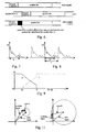
- Figure 1 is a schematical representation of constellation 16-QAM;
- Figure 2 is a diagram of the transfer function for a typical example of a transmission channel;
- Figure 3 diagrammatically shows the structure of an OFDM symbol for the DVB-T system;
- Figure 4 diagrammatically shows the structure of an OFDM symbol for the CD3-OFDM system according to the above Italian patent No. 1 281 947;
- Figure 5 is a block diagram of a receiver according to the prior art (CD3-OFDM concept);
- Figure 6 represents the effect of an echo having a delay with respect to the main signal that is longer than the guard interval;
- Figure 7 is a diagram showing an example of an impulse response, with echoes longer than the guard interval T g ;
- Figure 8 is a diagram similar to Figure 7, in the case of an sub-sampling of the frequency response H , with a
distance 1/T r between the samples; - Figure 9 is a diagram showing a split of the echo power into useful power C and interfering power I, with respect to the echo delay t and the parameters of the receiver;
- Figure 10 is a block diagram of a typical embodiment of the invention to achieve lock-in of the CD3-OFDM system; and
- Figure 11 is a graphical representation of the behavior of the phase for a signal that is the sum of two signals.
- Figure 7 shows a typical example of a channel impulse response that is not limited to T g . The estimate of the channel transfer function H(n,k) (obtained by dividing the received signal by the estimate of the transmitted signal as shown by expression (1)) is sampled, and the frequency gap between the samples is equal to the
distance 1/T r = 1/(αT u ) between the carriers known by the receiver or estimated by it (α = I in case of an estimate by the CD3-OFDM method, α = 1/3 in case of the DVB-T standard). This means that the input signal H to the frequency-domain filter (or interpolator) exhibits a spectrum having periodical replicas repeating at distances T r = αT u (Figure 8). Accordingly, it is necessary that the bandwidth T f of the frequency-domain filter is such that it imparts a strong attenuation in the neighbourhood of T r = αT u , in order to avoid the "aliasing" phenomenon for the "main signal" (null delay), while, for echoes with delays longer than T r , the "aliasing" phenomenon cannot be avoided. In the case that α = 1 (CD3-OFDM receiver), the first replica of the signal appears with a very long delay and does not place any significant restraints on the bandwidth T f , however, in case that α = 1/3 (DVB-T norm) the filter bandwidth should be less than the theoretical limit T u /3. Moreover, in order to limit the complexity of the interpolator filter, T f should be further reduced. - In order to achieve a reliable estimate of the channel impulse response even in presence of echoes beyond T g , the invention consists in using a frequency-domain filter with "bandwidth" T f , such that all echoes that it is desired to equalize fall within its "passband" (e.g., T f = 2T g ). Obviously, it is necessary that T f is less than T r , so that it allows replicas of h c (t) to be filtered.
- The following expression shows how a different filter influences the splitting of the power C i of the i-th echo into useful power C and interfering power I, as a function of the echo delay t and of the filter bandwidth T f (Figure 9):


- Accordingly, echoes with a delay in the range T g to T f contribute both as useful signals and as interfering signals. With previously known equalization systems, where T f = T g , w i is a "window" function of duration T g , and the power of all the echoes outside the guard interval turns out to be interfering.
- Surprisingly, it turns out that by widening the bandwidth T f of the frequency-domain filter, in allowing a better estimate of the channel transfer function to be achieved, the power received with a delay longer than the guard interval T g is made partially useful, thus improving the overall performance of the system. Accordingly, the system achieves elimination of the second of the two degradation phenomena mentioned under (a) and (b).
- Where the known symbol is present in the signal frame, the CD3-OFDM system as disclosed in Italian patent No. 1 281 947 mentioned above will operate in presence of echoes outside the guard interval, provided that the frequency-domain filter with "bandwidth" T g is replaced with one having a "bandwidth" equal to the longest echo that it is desired to equalize. This involves an increase of the residual noise upon the estimate of H (n,k), which increase can be compensated by installing a time-domain filter having a narrower bandwidth (for instance, for T f = 2T g , a time-domain filter may be used which averages, in each carrier, between two successive OFDM symbols). Such concept of broadening the filter bandwidth can only be applied marginally with systems using an equalization based on pilot carriers. Indeed, with reference to the example of the DVB-T standard, using sub-sampling of the pilot carriers α = 1.3, the interpolator filter's bandwidth can be widened only from T g to a theoretical maximum of T u 3, in compliance with the sampling theorem.
- It can be seen from the above explanation that in the case of equalization based on pilot carriers according to the DVB-T norm, T r is small because of the sub-sampling (i.e., the spurious replicas of the estimated transfer function are quite close to one another): consequently, due to the above restraint T f < T r on the passband of the frequency-domain filter, the practically feasible widening of the "passband" is moderate. Much wider would be the feasible bandwidth with the CD3-OFDM equalization method according to the above Italian pat. No. 1 281 947. However, in the present circumstances this method cannot be used, since it requires the presence of a reference symbol that is not contemplated in the norm as currently adopted.
- In the CD3-OFDM procedure, the usefulness of the reference symbol is limited to the initial stage of the process (lock-in stage), after which equalization proceeds indefinitely, based on previous symbols, after they have been corrected, re-encoded and re-modulated. According to the invention, an improvement of the CD3-OFDM equalization method of said prior patent is provided, by which a lock-in of the CD3-OFDM procedure can be achieved even without a reference symbol, although with use of pilot carriers, as, for instance, with the DVB-T standard, even while such a sub-sampling in the frequency domain is used that makes it impossible to achieve a proper estimate of the channel transfer function in presence of echoes outside the guard interval.
- If the signal frame does not contain a reference symbol, but only pilot carriers in known positions in the spectrum, the invention makes it possible to achieve lock-in of the CD3-OFDM system even in presence of echoes outside the guard interval, according to the method disclosed below. The disclosure refers to the diagram of Figure 10.
- The system comprises three branches acting on the signals in reception after the FFT:
- a) Fast estimate of the channel transfer function on the pilot carriers, with an interpolator filter having a "bandwidth" T f < αT u . This estimate is coarse, because it is limited to echoes with a delay shorter than T f .
- b) Slow channel estimate on data carriers using a filter with wide "bandwidth" T f ' which is capable of evaluating even the echoes outside the interval T f .
- c) Fast channel estimate based on CD3, using a filter with wide "bandwidth" T f '.
- It should be appreciated that branch (c) on Figure 10, as well as the bottom chain for equalization, M-QAM demodulation ad FEC decoding, correspond to the CD3-OFDM scheme of Figure 5.
- The transfer function H (n,k) in the corresponding frequency positions is estimated in branch (a), based on the received pilot carriers, by means of formula (1), similarly to a conventional receiver based on pilot carriers. By interpolation in the time domain (or, more simply, accumulation of the pilot carriers upon four successive OFDM symbols) and in the frequency domain the estimate of the channel transfer function Ĥ p (n,k) is obtained and is used for equalizing the signal. The interpolation in the frequency domain should be performed by a filter having a maximum bandwidth T f < αT u (such that it guarantees suppression of the replicas of the channel impulse response). By means of an estimate of the reliability of the signal decoded by the FEC, the "quality" of Ĥp(n,k) is evaluated. The estimate of the "quality" of the decoded signal can be evaluated by analyzing the rate of growth of the metrics of the Viterbi algorithm in the FEC. Alternatively, the error rate on known bytes could be measured (e.g., synchronization byte in the DVB-T standard). If the quality is sufficient to allow the CD3-OFDM system to be locked in, the switch shifts to position C and processing skips to stage 3 of the procedure directly. This can be obtained if there are no echoes with significant power and with delays longer than T f . Otherwise, the switch shifts to position B and processing goes on to
stage 2 of the lock-in procedure. - In branch (a), computation of the coarse estimate Ĥ p (n,k) of the channel transfer function, which does not take into account the echoes outside T f , continues on the basis of the received pilot carriers. Simultaneously, a nonlinearity and a time-domain filter (on successive OFDM symbols) is applied to each of the data carriers in order to estimate the channel transfer function, leaving aside a phase ambiguity of whole multiples of π/2 radians (due to the symmetry of the M-QAM constellations to π/2 rotations). The method used for this estimate can be any of the algorithms usually suggested for the estimate of the channel (carrier recovery) in digital, coherent-demodulation systems. For instance, the nonlinearity could be raising the received signal to the fourth power (an algorithm described in D. Efstathiou, P. Fines, A. H. Aghvami, "Preamhle-less Non-Decision-Aided (NDA) Techniques for 16-OAM Carrier Phase Recovery and Gain Error Correction, for Burst Transmissions", proceedings of the GLOBECOM '93 Conference, 29 November - 2 December 1993). The time-domain filter can be implemented by an average operator over n successive OFDM symbols; in that case the estimate Ĥ a (n,k) will be obtained as:


where E[•] denotes the average value. - The invention resides in the method for resolving the mπ/2 phase ambiguity in the estimate Ĥ a (n,k).
- Figure 11 graphically shows the signal resulting from the sum of a main signal and an echo, for two different echo amplitudes. The phase of the echo vector can take any value depending on the associated delay, as shown by the circumference in the drawing. It can be seen that the maximum phase difference of the resulting vector from the main signal increases as the amplitude of the echo becomes similar to the one of the main signal.
- As mentioned above, the estimate algorithm based on pilot carriers in branch (a) allows the phase of the channel transfer function to be evaluated, for echoes having a delay shorter than the band T f of the frequency interpolator filter. This means that, when echoes with a delay longer than T f are present, the phase error in the estimate Ĥ p (n,k) will be the larger, the greater is the amplitude of such echoes. However, if such error turns out to be less than π/4 in absolute value, then the phase information contained in Ĥ p (n,k) can be used to resolve the phase ambiguity in Ĥ d (n,k), by associating to it the phase closer to the one of Ĥ p (n,k). From Figure 9 it can be seen that, as the echo delay increases, there is a reduction of the useful power contribution and an increase of the contribution from the interfering power associated with the echo. Even if the equalization process is assumed to be perfect, the systems under consideration can only operate correctly with C/I ratios larger than a limit value (C/I) L , which depends mainly on the chosen constellation and on the adopted type of FEC coding. Consequently, if the condition C/I > (C/I) L is imposed in formula (1), it follows that the equalization system should be capable of correctly operating with echoes outside the guard interval T g having an amplitude decreasing as the the associated delay increases. Therefore, if bandwidth T f of the interpolator filter in branch (a) yields a good estimate of high-power echoes within and closely outside the guard interval up to T f , the method of the invention provides correct resolution of the phase ambiguity for echoes having a delay longer than T f up to T f ' and a reduced amplitude, which generate phase rotations that are usually smaller than π/4 in absolute value.
- Therefore, according to the invention, the estimate Ĥ d (n,k) of the channel transfer function is given by:


where m 0 is the value ofm such that the phase difference [arg( Ĥ a (n,k)) - arg( Ĥp(n,k))] is at a minimum (resolution of the π/2 phase ambiguity). - Subsequently, the channel estimate as derived from the data carriers is integrated with the estimate evaluated from the pilot carriers, and the result is filtered in the frequency domain using a "wide" filter having "bandwidth" T f '. It should be noted that, in the hardware implementation, the frequency-domain filters in branches (a), (b) e (c) could be a single physical filter, where the coefficients and the bandwidth are changed depending on the stage ((a), (b), o (c)) of the algorithm.
- A second method for resolving the phase ambiguity is based on the following consideration. The phase jumps between successive samples of the transfer function H(n,k) depend on the amplitude of the echo and on its delay (Figure 11). The shorter is the echo delay, the smaller is the phase variation from one frequency sample to the next in H(n,k); the smaller the echo amplitude, the smaller is the phase variation from one frequency sample to the next in H (n,k). Therefore, since an estimate of the transfer function H(n,k) is available to the receiver for values k corresponding to the pilot carriers (after filtering in the time domain), such estimate can be used to resolve the phase ambiguity (mπ/2) of the transfer function corresponding to the data carriers. The invention provides for associating Ĥ d (n,k) with the phase closest to the phase of the pilot carrier that is adjacent in the frequency domain. This algorithm is sub-optimal with respect to the previous one, because powerful echoes, even inside the guard interval, could give rise to large phase jumps from one carrier to the next, and, consequently, to a wrong resolution of the phase ambiguity.
- Variations in the above described methods of resolving the phase ambiguity (mπ/2) may be made, which will in each case be based on phase information from the pilot carriers and from the adjacent data carriers for which the phase ambiguity has been previously resolved, all within the scope of the invention. For instance, another approach could be to search for the minimum phase difference with respect to a data carrier of adjacent frequency, for which the phase ambiguity has already been resolved in the same way, or with another of the above described methods.
- In stage 2 (switch in position B), the quality of Ĥ d (n,k) is again evaluated by estimating the reliability of the signal as decoded by the FEC, until such quality becomes sufficient to insure convergence of the CD3-OFDM algorithm. Alternatively, a fixed lock-in time could be identified (the number of OFDM symbols over which the time average should be computed), on the basis of a laboratory test using a variety of echo patterns. At this point, the switch is shifted to position C and processing proceeds to stage 3.
- This stage coincides with the end of the lock-in stage in the estimator of H (n,k), when the CD3-OFDM equalization algorithm can operate correctly with a filter that has been widened to bandwidth T f '. This stage continues for the remaining duration of the reception, until, for any reason, the loop should become unlocked.
- The result of the estimate of H (n,k) in
stage 2, with either of the methods suggested for resolving the phase ambiguity, is all the more accurate as the number of averaged symbols Q is larger, usually a few tens; this, of course, involves a slowdown in tracking the channel transfer function, although, in the preferred embodiment of the receiver (Fig. 10), this only happens in the start-up stage of the receiver. Indeed, the CD3-OFDM channel estimate procedure, once triggered, is able to perform the estimate symbol by symbol, and to quickly track all changes in the channel characteristics. -
Stage 2 of the method according to the invention may also continue for the entire duration of the reception, without using the CD3-OFDM channel estimate algorithm, and therefore without a transition to stage 3. In that case, the slow time-domain filter in branch (b) drastically slows down the ability of the system to track changes in the propagation channel (e.g., due to Doppler effect) for the entire duration of the reception. Accordingly, though applying the invention to the equalization system based on the CD3-OFDM system requires a quasi-stationary channel only for a brief lock-in interval, using the invention with the equalization system based on the pilot carriers alone does not provide a sufficient adjustment speed in presence of channel variations and echoes outside the guard interval.
Claims (14)
- A method for receiving digital signals over a channel as a sequence of C-OFDM multicarrier symbols (x(n,k)) each being preceded by a guard interval and of the type including pilot carriers and being free from reference symbols, the method comprising the steps of:- demodulating the received signals by reconstructing its elementary components (y((n,k)),- equalizing said elementary components (y(n,k)) by dividing them by corresponding values of an estimated channel transfer function (Ĥ(n-1, k)) being derived from a previously received symbol (y(n-1,k)) by dividing its elementary components by the estimates (x̂(n-1,k)) of the respective transmitted symbol (x(n-1,k)) as reconstructed in the receiver after equalization, FEC correction, re-encoding and remapping, and filtering the resulting quotients in the time domain and in the frequency domain with a first equivalent bandwidth that is greater than the duration of the guard interval,the method being characterized by the steps of:- obtaining an initial estimate (Ĥp(n,k)) of the channel transfer function in a first stage by extracting the pilot carriers from the signal, deriving the channel impulse response for each pilot carrier by interpolating in the time domain using successive symbols and in the frequency domain by filtering with a second equivalent bandwidth (Tf) not greater than the duration of the repetition interval (Tr ⊜ αTu) of the channel impulse response due to the sub-sampling in the frequency domain,- obtaining the estimate of the channel transfer function in a second stage by filtering said quotients in the frequency domain with the first equivalent bandwidth (Tf') equal to the maximum delay of the echoes that are desired to equalize, and- switching from the first stage to the second stage depending on the reliability of the initial estimate of the transfer function.
- Method for receiving digital signals according to claim 1, wherein the received, demodulated and equalized signal is decoded by FEC decoding, characterized in that the reliability of said initial estimate of the channel transfer function ( Ĥ p (n,k)) is evaluated by analyzing the rate of growth of the metrics in a Viterbi algorithm of the decoding.
- Method for receiving digital signals according to claim 1, characterized in that the reliability of said initial estimate of the channel transfer function ( Ĥ p (n,k)) is evaluated by measuring the error rate in predetermined known bytes that are contained in the transmitted signal.
- Method for receiving digital signals according to claim 2 or 3, characterized in that, if during said first stage the reliability of the initial estimate of the channel transfer function ( Ĥ p (n,k)) is worse than a predetermined value, before switching to the second stage, switching to a third stage, wherein a nonlinearity and a time-domain filter are applied to the data carriers in a parallel processing in order to improve the estimate of the channel transfer function, with a phase ambiguity of multiples of π/2 radians, and the ambiguity is resolved by assuming as a valid phase the one for which the phase difference from the initial estimate of the channel transfer function ( Ĥ p (n,k)) is a minimum.
- Method for receiving digital signals according to claim 2 or 3, characterized in that, if during said first stage the reliability of the initial estimate of the channel transfer function ( Ĥ p (n,k)) is worse than a predetermined value, before switching to the second stage, switching to a third stage, wherein a nonlinearity and a time-domain filter are applied to the data carriers in a parallel processing in order to improve the estimate of the channel transfer function, with a phase ambiguity of multiples of π/2 radians, and the ambiguity is resolved by assuming as a valid phase the one whose difference from the phase of the pilot carrier that is closer in frequency is a minimum.
- Method for receiving digital signals according to claim 2 or 3, characterized in that, if during said first stage the reliability of the initial estimate of the channel transfer function ( Ĥ p (n,k)) is worse than a predetermined value, before switching to the second stage, switching to a third stage, wherein a nonlinearity and a time-domain filter are applied to the data carriers in a parallel processing in order to improve the estimate of channel transfer function, with a phase ambiguity of multiples of π/2 radians, and the ambiguity is resolved by assuming as a valid phase the one having minimum difference from the phase of a pilot carrier or data carrier, which is adjacent in frequency, of which the phase ambiguity has already been resolved.
- Method for receiving digital signals according to claim 4 or 5 or 6, characterized in that said non-linearity is a raising of the received signal to the fourth power.
- Method for receiving digital signals according to claim 4, 5, 6 or 7, characterized in that the time-domain filtering is stopped after a predetermined number of OFDM symbols and said second stage is started.
- Apparatus for receiving digital signals over a channel as a sequence of C-OFDM multicarrier symbols (x(n,k)) each being preceded by a guard interval and of the type including pilot carriers and being free from reference symbols, said apparatus comprising- demodulating means for demodulating the received signals by reconstructing its elementary components (y(n,k)),- equalizing means for equalizing said elementary components (y(n,k)) by dividing them by corresponding values of an estimated channel transfer function being Ĥ(n-1, k) derived from a previously received symbol (y(n-1,k)) by dividing its elementary components by the estimates (x̂(n-1,k)) of the respective transmitted symbol (x(n-1,k)) as reconstructed in the receiver after equalization, FEC correction, re-encoding and remapping, and filtering means for filtering the resulting quotients in the time domain and in the frequency domain with a first equivalent bandwidth that is greater than the duration of the guard interval,the apparatus being characterized in that it further comprises- first means for obtaining an initial estimate (Ĥp(n,k)) of the channel transfer function by extracting the pilot carrier frequencies from the signal, deriving the channel impulse response for each pilot carrier by interpolating in the time domain using successive symbols and in the frequency-domain by filtering with a second equivalent bandwidth (Tf) not greater than the duration of the repetition interval (Tr = αTu) of the channel impulse response due to the sub-sampling in the frequency domain;- second means for obtaining the estimate (Ĥ(n,k)) of the channel transfer function by filtering said quotients in the frequency domain with the first equivalent bandwidth (Tf') equal to the maximum delay of the echoes that are desired to equalize, and- switching means for switching the operation of the apparatus from said first means to said second means depending on the reliability of the initial estimate of the transfer function.
- Apparatus for receiving digital signals according to claim 9, characterized in that it further comprises third means for applying a non-linearity and a time-domain filtering to the data carriers in order to improve the estimate of channel transfer function, with a phase ambiguity of multiples of π/2 radians, and means for resolving the phase ambiguity by assuming as a valid phase the one for which the phase difference from the initial estimate of the channel transfer function ( Ĥ p (n,k)) is a minimum, and in that said switching means, if the reliability of the initial estimate of the channel transfer function ( Ĥ p (n,k)) in said first means turns out to be worse than a predetermined value, switch the operation of the apparatus from the first to the third means before switching to the second means.
- Apparatus for receiving digital signals according to claim 9, characterized in that it further comprises third means for applying a non-linearity and a time-domain filtering to the data carriers in order to improve the estimate of the channel transfer function ( Ĥ (n,k)), with a phase ambiguity of multiples of π/2 radians, and means for resolving the phase ambiguity by assuming as a valid phase the one for which the phase difference from the phase of the pilot carrier closest in frequency is a minimum, and in that said switching means, if said reliability of the initial estimate of the channel transfer function ( Ĥ p (n,k)) in said first means is worse than a predetermined value, switch the operation of the apparatus from the first to the third means before switching to the second means.
- Apparatus for receiving digital signals according to claim 9, characterized in that it further comprises third means for applying a non-linearity and a time-domain filtering to the data carriers in order to improve the estimate of the channel transfer function ( Ĥ (n,k)), with a phase ambiguity of multiples of π/2 radians, and means for resolving the phase ambiguity by assuming as a valid phase the one having minimum difference from the phase of pilot carrier or a data carrier, which is adjacent in frequency, of which the phase ambiguity has already been resolved, and in that said switching means, if said reliability of the initial estimate of the channel transfer function ( Ĥ p (n,k)) in said first means is worse than a predetermined value, switch the operation of the apparatus from the first to the third means before switching to the second means.
- Apparatus for receiving digital signals according to any of claims 10, 11 or 12, characterized in that said means for applying a nonlinearity are means for raising the received signal to the fourth power.
- Apparatus for receiving digital signals according to any of claims 10 to 13, characterized in that said switching means is adapted to switch from said third means to said second means after reception of a predetermined number of OFDM symbols.
Applications Claiming Priority (2)
| Application Number | Priority Date | Filing Date | Title |
|---|---|---|---|
| IT96TO000867A IT1288778B1 (it) | 1996-10-25 | 1996-10-25 | Procedimento e apparato di ricezione di segnali numerici in multiplex codificato e divisione di frequenze. |
| ITTO960867 | 1996-10-25 |
Publications (3)
| Publication Number | Publication Date |
|---|---|
| EP0838928A2 EP0838928A2 (en) | 1998-04-29 |
| EP0838928A3 EP0838928A3 (en) | 2001-01-31 |
| EP0838928B1 true EP0838928B1 (en) | 2006-06-21 |
Family
ID=11414982
Family Applications (1)
| Application Number | Title | Priority Date | Filing Date |
|---|---|---|---|
| EP97203254A Expired - Lifetime EP0838928B1 (en) | 1996-10-25 | 1997-10-18 | Equalisation of multicarrier signals |
Country Status (4)
| Country | Link |
|---|---|
| EP (1) | EP0838928B1 (en) |
| AT (1) | ATE331373T1 (en) |
| DE (2) | DE69736162D1 (en) |
| IT (1) | IT1288778B1 (en) |
Families Citing this family (20)
| Publication number | Priority date | Publication date | Assignee | Title |
|---|---|---|---|---|
| DE19735216C2 (en) * | 1997-08-14 | 1999-07-15 | Deutsche Telekom Ag | Method for transmitting multicarrier signals with a coefficient setting of the time domain equalizer |
| WO1999062207A1 (en) * | 1998-05-26 | 1999-12-02 | Jean Armstrong | Data transmission and reception in multicarrier modulation systems |
| GB2346520A (en) * | 1998-11-09 | 2000-08-09 | Wi Lan Inc | Data recovery in an OFDM system exploiting pilot subcarriers |
| US7177378B2 (en) | 2001-03-30 | 2007-02-13 | Telefonaktiebolaget Lm Ericsson (Publ) | Minimization of error contributions in a DMT system |
| EP1246422A1 (en) * | 2001-03-30 | 2002-10-02 | Telefonaktiebolaget Lm Ericsson | Equaliser for multicarrier system |
| US6961545B2 (en) | 2001-04-09 | 2005-11-01 | Atheros Communications, Inc. | Method and system for providing antenna diversity |
| FR2825551B1 (en) * | 2001-05-30 | 2003-09-19 | Wavecom Sa | METHOD FOR ESTIMATING THE TRANSFER FUNCTION OF A TRANSMISSION CHANNEL OF A MULTI-CARRIER SIGNAL, METHOD OF RECEIVING A DIGITAL SIGNAL, AND RECEIVER OF A MULTI-CARRIER SIGNAL THEREOF |
| AT411002B (en) * | 2001-09-14 | 2003-09-25 | Ftw Forschungszentrum Telekomm | METHOD FOR TRANSMITTING DATA BY MULTI-CARRIER MODULATION |
| EP1313282B1 (en) * | 2001-11-15 | 2004-09-08 | Matsushita Electric Industrial Co., Ltd. | Method and apparatus for OFDM (orthogonal frequency division multiplexing) demodulation |
| DE10225663B4 (en) * | 2002-06-10 | 2005-12-29 | Fraunhofer-Gesellschaft zur Förderung der angewandten Forschung e.V. | Method and device for carrying out a channel estimation |
| DE10248507A1 (en) * | 2002-10-11 | 2004-04-22 | IHP GmbH - Innovations for High Performance Microelectronics/Institut für innovative Mikroelektronik | Error correction method for multiplex signals, esp. OFDM in digital audio broadcast (DAB), involves compensating or balancing step of partial elimination of phase error accumulation of part signal |
| GB2412552A (en) * | 2004-03-26 | 2005-09-28 | Sony Uk Ltd | Receiver |
| GB2412551A (en) | 2004-03-26 | 2005-09-28 | Sony Uk Ltd | Receiver |
| KR100585155B1 (en) * | 2004-08-19 | 2006-05-30 | 삼성전자주식회사 | Frequency Domain Channel Evaluation Method of DVT-T Receiver Using Complex Domain |
| DE602006004975D1 (en) * | 2005-03-01 | 2009-03-12 | Panasonic Corp | OFDM receiver and reception method |
| CN102984098B (en) * | 2006-10-05 | 2016-11-23 | 科达无线私人有限公司 | For improving the system and method for the receiver performance in communication network |
| WO2008146242A2 (en) | 2007-05-30 | 2008-12-04 | Nxp B.V. | Frequency domain interpolation based receiver for multicarrier signals |
| IT1394614B1 (en) * | 2008-07-29 | 2012-07-05 | Rai Radiotelevisione Italiana S P A | METHOD AND RECEPTION SYSTEM OF NUMERICAL SIGNALS IN MULTIPLEX CODED TO FREQUENCY DIVISION FOR TRANSMISSION SYSTEMS, IN PARTICULAR TO SPACE DIVERSITY |
| CN104333527B (en) * | 2014-11-26 | 2019-05-21 | 西安烽火电子科技有限责任公司 | A kind of aircraft COFDM modulation-demo-demodulation method |
| CN111432473B (en) * | 2019-01-09 | 2022-11-18 | 成都鼎桥通信技术有限公司 | Carrier scheduling method and device for digital cluster |
-
1996
- 1996-10-25 IT IT96TO000867A patent/IT1288778B1/it active IP Right Grant
-
1997
- 1997-10-18 DE DE69736162T patent/DE69736162D1/en not_active Expired - Lifetime
- 1997-10-18 EP EP97203254A patent/EP0838928B1/en not_active Expired - Lifetime
- 1997-10-18 AT AT97203254T patent/ATE331373T1/en not_active IP Right Cessation
- 1997-10-18 DE DE0838928T patent/DE838928T1/en active Pending
Also Published As
| Publication number | Publication date |
|---|---|
| EP0838928A3 (en) | 2001-01-31 |
| IT1288778B1 (it) | 1998-09-24 |
| EP0838928A2 (en) | 1998-04-29 |
| ITTO960867A1 (en) | 1998-04-25 |
| DE69736162D1 (en) | 2006-08-03 |
| ATE331373T1 (en) | 2006-07-15 |
| DE838928T1 (en) | 1998-11-19 |
Similar Documents
| Publication | Publication Date | Title |
|---|---|---|
| EP1376965B1 (en) | Multi-path equalization for orthogonal frequency division multiplexing communication system | |
| EP0838928A2 (en) | Equalisation of multicarrier signals | |
| US7187736B2 (en) | Reducing interference in a GSM communication system | |
| EP1872551B1 (en) | Time domain windowing and inter-carrier interference cancellation | |
| JP4420505B2 (en) | Modulation / demodulation method for multilevel digital modulation signal and orthogonal frequency division multiplexing system | |
| US7843805B2 (en) | Method and circuit for frequency offset estimation in frequency domain in the orthogonal frequency division multiplexing baseband receiver for IEEE 802.11a/g wireless LAN standard | |
| US7161896B1 (en) | Channel estimation in a multicarrier radio receiver | |
| CN101341677B (en) | Inter-carrier interference removal device and reception device using the same | |
| KR100377257B1 (en) | Method and apparatus for fine frequency synchronization in multi-carrier demodulation systems | |
| CN101228750B (en) | Reduced complexity channel estimation in OFDM systems | |
| JP3492565B2 (en) | OFDM communication device and detection method | |
| US20070036232A1 (en) | Ofdm reception apparatus and ofdm reception method | |
| US20040218519A1 (en) | Apparatus and method for estimation of channel state information in OFDM receivers | |
| US10461790B2 (en) | Method for compensation of phase noise effect on data transmission in radio channel | |
| EP2289216B1 (en) | Methods for estimating a residual frequency error in a communications system | |
| KR19990043408A (en) | Method and apparatus for simple frequency acquisition of orthogonal split-band systems | |
| AU2009202588A1 (en) | Channel estimation for communication systems | |
| EP2077649A1 (en) | Channel estimation method and channel estimator utilizing the same | |
| KR20010042709A (en) | Differential coding and carrier recovery for multicarrier systems | |
| US20100074346A1 (en) | Channel estimation in ofdm receivers | |
| JP4285845B2 (en) | Receiver | |
| US6845133B2 (en) | Method and device for processing signals of a digital transmission system | |
| Rinne et al. | An improved equalizing scheme for orthogonal frequency division multiplexing systems for time-variant channels | |
| US7715486B2 (en) | Method and device for estimating the transfer function of the transmission channel for a COFDM demodulator | |
| CN1551587A (en) | Improved channel decoding for multi-carrier signal transmission |
Legal Events
| Date | Code | Title | Description |
|---|---|---|---|
| PUAI | Public reference made under article 153(3) epc to a published international application that has entered the european phase |
Free format text: ORIGINAL CODE: 0009012 |
|
| AK | Designated contracting states |
Kind code of ref document: A2 Designated state(s): AT BE CH DE DK ES FI FR GB IE IT LI NL |
|
| AX | Request for extension of the european patent |
Free format text: AL;LT;LV;RO;SI |
|
| EL | Fr: translation of claims filed | ||
| TCNL | Nl: translation of patent claims filed | ||
| DET | De: translation of patent claims | ||
| PUAL | Search report despatched |
Free format text: ORIGINAL CODE: 0009013 |
|
| AK | Designated contracting states |
Kind code of ref document: A3 Designated state(s): AT BE CH DE DK ES FI FR GB GR IE IT LI LU MC NL PT SE |
|
| AX | Request for extension of the european patent |
Free format text: AL;LT;LV;RO;SI |
|
| AKX | Designation fees paid | ||
| RBV | Designated contracting states (corrected) |
Designated state(s): AT BE CH DE DK ES FI FR GB GR IE IT LI |
|
| RBV | Designated contracting states (corrected) |
Designated state(s): AT BE CH DE DK ES FI FR GB IE IT LI NL |
|
| 17P | Request for examination filed |
Effective date: 20010731 |
|
| 17Q | First examination report despatched |
Effective date: 20040930 |
|
| GRAP | Despatch of communication of intention to grant a patent |
Free format text: ORIGINAL CODE: EPIDOSNIGR1 |
|
| GRAS | Grant fee paid |
Free format text: ORIGINAL CODE: EPIDOSNIGR3 |
|
| GRAA | (expected) grant |
Free format text: ORIGINAL CODE: 0009210 |
|
| AK | Designated contracting states |
Kind code of ref document: B1 Designated state(s): AT BE CH DE DK ES FI FR GB IE IT LI NL |
|
| PG25 | Lapsed in a contracting state [announced via postgrant information from national office to epo] |
Ref country code: NL Free format text: LAPSE BECAUSE OF FAILURE TO SUBMIT A TRANSLATION OF THE DESCRIPTION OR TO PAY THE FEE WITHIN THE PRESCRIBED TIME-LIMIT Effective date: 20060621 Ref country code: IT Free format text: LAPSE BECAUSE OF FAILURE TO SUBMIT A TRANSLATION OF THE DESCRIPTION OR TO PAY THE FEE WITHIN THE PRE;WARNING: LAPSES OF ITALIAN PATENTS WITH EFFECTIVE DATE BEFORE 2007 MAY HAVE OCCURRED AT ANY TIME BEFORE 2007. THE CORRECT EFFECTIVE DATE MAY BE DIFFERENT FROM THE ONE RECORDED.SCRIBED TIME-LIMIT Effective date: 20060621 Ref country code: FI Free format text: LAPSE BECAUSE OF FAILURE TO SUBMIT A TRANSLATION OF THE DESCRIPTION OR TO PAY THE FEE WITHIN THE PRESCRIBED TIME-LIMIT Effective date: 20060621 Ref country code: BE Free format text: LAPSE BECAUSE OF FAILURE TO SUBMIT A TRANSLATION OF THE DESCRIPTION OR TO PAY THE FEE WITHIN THE PRESCRIBED TIME-LIMIT Effective date: 20060621 Ref country code: AT Free format text: LAPSE BECAUSE OF FAILURE TO SUBMIT A TRANSLATION OF THE DESCRIPTION OR TO PAY THE FEE WITHIN THE PRESCRIBED TIME-LIMIT Effective date: 20060621 |
|
| REG | Reference to a national code |
Ref country code: GB Ref legal event code: FG4D |
|
| REG | Reference to a national code |
Ref country code: CH Ref legal event code: NV Representative=s name: PA ALDO ROEMPLER Ref country code: CH Ref legal event code: EP |
|
| REG | Reference to a national code |
Ref country code: IE Ref legal event code: FG4D |
|
| REF | Corresponds to: |
Ref document number: 69736162 Country of ref document: DE Date of ref document: 20060803 Kind code of ref document: P |
|
| PG25 | Lapsed in a contracting state [announced via postgrant information from national office to epo] |
Ref country code: DK Free format text: LAPSE BECAUSE OF FAILURE TO SUBMIT A TRANSLATION OF THE DESCRIPTION OR TO PAY THE FEE WITHIN THE PRESCRIBED TIME-LIMIT Effective date: 20060921 |
|
| PG25 | Lapsed in a contracting state [announced via postgrant information from national office to epo] |
Ref country code: DE Free format text: LAPSE BECAUSE OF FAILURE TO SUBMIT A TRANSLATION OF THE DESCRIPTION OR TO PAY THE FEE WITHIN THE PRESCRIBED TIME-LIMIT Effective date: 20060922 |
|
| PG25 | Lapsed in a contracting state [announced via postgrant information from national office to epo] |
Ref country code: ES Free format text: LAPSE BECAUSE OF FAILURE TO SUBMIT A TRANSLATION OF THE DESCRIPTION OR TO PAY THE FEE WITHIN THE PRESCRIBED TIME-LIMIT Effective date: 20061002 |
|
| NLV1 | Nl: lapsed or annulled due to failure to fulfill the requirements of art. 29p and 29m of the patents act | ||
| PLBE | No opposition filed within time limit |
Free format text: ORIGINAL CODE: 0009261 |
|
| STAA | Information on the status of an ep patent application or granted ep patent |
Free format text: STATUS: NO OPPOSITION FILED WITHIN TIME LIMIT |
|
| EN | Fr: translation not filed | ||
| 26N | No opposition filed |
Effective date: 20070322 |
|
| PG25 | Lapsed in a contracting state [announced via postgrant information from national office to epo] |
Ref country code: FR Free format text: LAPSE BECAUSE OF FAILURE TO SUBMIT A TRANSLATION OF THE DESCRIPTION OR TO PAY THE FEE WITHIN THE PRESCRIBED TIME-LIMIT Effective date: 20070309 |
|
| REG | Reference to a national code |
Ref country code: CH Ref legal event code: PCAR Free format text: ALDO ROEMPLER PATENTANWALT;BRENDENWEG 11 POSTFACH 154;9424 RHEINECK (CH) |
|
| PG25 | Lapsed in a contracting state [announced via postgrant information from national office to epo] |
Ref country code: FR Free format text: LAPSE BECAUSE OF FAILURE TO SUBMIT A TRANSLATION OF THE DESCRIPTION OR TO PAY THE FEE WITHIN THE PRESCRIBED TIME-LIMIT Effective date: 20060621 |
|
| PGFP | Annual fee paid to national office [announced via postgrant information from national office to epo] |
Ref country code: IE Payment date: 20121004 Year of fee payment: 16 |
|
| PGFP | Annual fee paid to national office [announced via postgrant information from national office to epo] |
Ref country code: IT Payment date: 20121023 Year of fee payment: 16 Ref country code: GB Payment date: 20121005 Year of fee payment: 16 |
|
| PGFP | Annual fee paid to national office [announced via postgrant information from national office to epo] |
Ref country code: CH Payment date: 20130110 Year of fee payment: 16 |
|
| REG | Reference to a national code |
Ref country code: CH Ref legal event code: PL |
|
| GBPC | Gb: european patent ceased through non-payment of renewal fee |
Effective date: 20131018 |
|
| REG | Reference to a national code |
Ref country code: IE Ref legal event code: MM4A |
|
| PG25 | Lapsed in a contracting state [announced via postgrant information from national office to epo] |
Ref country code: CH Free format text: LAPSE BECAUSE OF NON-PAYMENT OF DUE FEES Effective date: 20131031 Ref country code: GB Free format text: LAPSE BECAUSE OF NON-PAYMENT OF DUE FEES Effective date: 20131018 Ref country code: LI Free format text: LAPSE BECAUSE OF NON-PAYMENT OF DUE FEES Effective date: 20131031 |
|
| PG25 | Lapsed in a contracting state [announced via postgrant information from national office to epo] |
Ref country code: IT Free format text: LAPSE BECAUSE OF NON-PAYMENT OF DUE FEES Effective date: 20131018 |
|
| PG25 | Lapsed in a contracting state [announced via postgrant information from national office to epo] |
Ref country code: IE Free format text: LAPSE BECAUSE OF NON-PAYMENT OF DUE FEES Effective date: 20131018 |