EP0838761A2 - Dynamic maps and server-based map editing - Google Patents
Dynamic maps and server-based map editing Download PDFInfo
- Publication number
- EP0838761A2 EP0838761A2 EP19970105958 EP97105958A EP0838761A2 EP 0838761 A2 EP0838761 A2 EP 0838761A2 EP 19970105958 EP19970105958 EP 19970105958 EP 97105958 A EP97105958 A EP 97105958A EP 0838761 A2 EP0838761 A2 EP 0838761A2
- Authority
- EP
- European Patent Office
- Prior art keywords
- dynamic
- map
- resource
- dynamic resource
- status
- Prior art date
- Legal status (The legal status is an assumption and is not a legal conclusion. Google has not performed a legal analysis and makes no representation as to the accuracy of the status listed.)
- Withdrawn
Links
Images


Classifications
-
- G—PHYSICS
- G06—COMPUTING; CALCULATING OR COUNTING
- G06F—ELECTRIC DIGITAL DATA PROCESSING
- G06F11/00—Error detection; Error correction; Monitoring
- G06F11/30—Monitoring
- G06F11/32—Monitoring with visual or acoustical indication of the functioning of the machine
- G06F11/324—Display of status information
- G06F11/328—Computer systems status display
Definitions
- This invention relates in general to electronic mapping of objects and, more particularly, to dynamic mapping for rendering updated status information of mapped objects at a glance.
- Printers, plotters and scanners are each a form of specialized computer and each has a unique configuration and installation need. When connected to a network, these devices often have additional configuration requirements. As such, to address the unique configuration needs, vendors have built proprietary solutions for administering their devices within any given networked environment. Specifically, vendors have been forced to construct specialized versions of their device management packages for the large existing matrix of platforms, based on various client and network operating system differences.
- a new trend within the computing industry is to provide management for networked devices over the Internet or World Wide Web. Furthermore, the management is provided via a standard Web Browser. This is because a standard Web Browser has many benefits, including location flexibility, cross-platform support, and adoption of industry standards. However, high level mapping showing device location and status information still has not been available or feasible even using existing Web Browser capabilities.
- HTML is an industry standard file format for Web pages. HTML specifies a syntax for viewing graphics and designating areas of a graphical image as "hot-spots" on Web pages. A hot spot provides a link to another Web page of information. By selecting on a hot spot (such as with a mouse or other pointing device), the user is able to move or "drill down” to the new Web page of information related to that hot spot. The use of hot-spots provides the drill down capability for accessing detail device information in conventional management packages that "list" the network devices.
- mapping of resources has been implemented for rendering better relational information of general layouts of facilities, offices, organizations, equipment, computers, peripherals, networks, other objects and the like.
- computing equipment and peripherals are networked together, it is not uncommon to map out the physical or logical layout of the network, equipment and peripherals, relative to each other and/or relative to the facilities layout in which the network is disposed.
- mapping provides a valuable resource for system administration purposes, for general use of the networked devices, and for device and facilities management in relation to the network.
- an electronic map depicts an office layout and the physical or relative locations of networked printers (i.e., dynamic resources) in the office
- the high-level map does not detail any specific printer status information without the user having to select that printer (its hot spot icon on the map) to request that information.
- any physical or locational change of a resource (device) relative to these "static" maps requires that the map be edited offline using a dedicated mapping or graphics (drawing) program. This results, undesirably, in an expenditure of a significant amount of time and effort by an administrator, user, or other individual capable of effectuating the changes on the map.
- an object of the present invention is to provide electronic dynamic mapping capabilities for relaying updated, at-a-glance status information of dynamic resources, and for providing easy editing capabilities of the resulting dynamic map in the event of a change in resource configurations.
- a method of generating and editing a dynamic map includes retrieving, from a network storage device, a static map of at least one static resource, retrieving at least one indicia representative of a dynamic resource for association with the static map, determining a status of the dynamic resource, and merging the static map, the at least one indicia, and the status of the dynamic resource for generating the dynamic map.
- the dynamic map generated depicts locations and up-to-date statuses of computer networked devices in reference to an environment defined by generally fixed physical relationships, such as an office layout.
- the dynamic resource indicia is displayed as a graphic icon, and the status of the dynamic resource is displayed as a distinguishing feature relative to the graphic icon, such as a change in background color around the icon.
- the dynamic resource is polled upon displaying of the dynamic map for an accurate, live, representation of the status of the dynamic resource. Furthermore, the dynamic resource is polled intermittently to regenerate the dynamic map for up-to-date statusing of the dynamic resource.
- the elements defining the dynamic map are stored at a server computing device, the dynamic map is generated from the elements at the server computing device, and the dynamic map is remotely accessible through a conventional Internet connection and web browser.
- Figure 1 is a depiction of a dynamic map according to principles of the invention.
- Figure 2 is a high level block diagram depicting the differing functions and features of the dynamic mapping utility of the present invention.
- Figure 3 depicts the static mapfile used in the generation of the dynamic map of Figure 1.
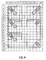
- Figure 4 depicts a grid overlaying the static mapfile of Figure 3, showing one tool for editing dynamic maps of the present invention.
- Figure 5 depicts a display screen showing a control panel for editing the dynamic maps of the present invention.
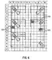
- Figure 6 shows how dynamic resources are placed onto the static map using the editing control of Figure 5.
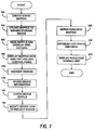
- Figure 7 is a flow diagram depicting a preferred method of the present invention for originally creating a dynamic map.
- Figure 8 is a flow diagram depicting a preferred method for viewing a dynamic map.
- FIG. 1 depicts a dynamic map according to principles of the present invention in a preferred embodiment.
- This dynamic map, and the dynamic mapping features of the present invention provide "live" information at a single glance concerning dynamic resources.
- the map is displayed electronically on a conventional display device, such as a computer monitor.
- the map is displayed using a conventional Web Browser, and the map is accessed from a Web server via the Internet.
- the reference implementation is based on software that executes within the Web server.
- the dynamic map of Figure 1 depicts a floor plan layout of a conventional modular office area having six cubicles 10, 15, 20, 25, 30 and 35 for personnel use or placement of equipment.
- Each cubicle is formed from modular walls 37 and is equipped with office equipment, such as desk tops 40, chairs 45 and computers 50.
- office equipment such as desk tops 40, chairs 45 and computers 50.
- These facilities represent the "static" facilities and layout of the map because they define physical relationships that are generally considered fixed relative to each other.
- Most resources, such as walls 37, desk tops 40 and chairs 45 are considered static because they are not capable of generating a status indicia indicative of a "state of operation".
- computers 50 are capable of generating a status indicia, they are considered static in this example for ease of discussion purposes.
- printers 55, 60 and 65 are also displayed on the map as graphic image indicia (or icons), but the printers represent dynamic devices (resources) on the map.
- the printers are dynamic devices because each is capable of generating a status signal for relaying information descriptive of its own respective state of operation.
- the map shows printer device 55 having a visibly distinguishable background color 57 relative to the printer icon itself 55.
- the background color is black and rectangular shaped in this example, other shapes or colors are usable to enhance the distinction of the background from the printer device icon itself.
- background 57 is the means used to communicate at-a-glance the status or state of operation of printer 55, and background 57 has been designated to indicate that printer 55 is in an error condition.
- printer 60 is depicted having a stippled background 62, indicative of printer 60 being in an offline status mode.
- printer 65 is depicted having a transparent background (i.e., no background is visible), indicative of printer 65 being in an on-line status or state of operation and ready for printing use.
- the background of each dynamic device has been arbitrarily chosen to reflect the current status of the respective device, it will be obvious that other colors, variations or implementations would also work to communicate the state of operation of the device with respect to the icon itself.
- the printers themselves are shown as the dynamic devices, other objects or components may also be dynamic and displayed accordingly.
- device identification (ID) information is dynamic because the ID information is stored in a removable control card (circuit card) within the device itself.
- the icon representing the device is also dynamic.
- each of the printers 55, 60 and 65 had previously emitted a status signal, indicative of the status of the respective printer, and the status signal was translated or merged with the respective printer indicia icon and with the office layout static map to produce the resultant dynamic map shown.
- An advantage of this dynamic map is that it provides to a user the ability to quickly observe the overall condition or status of all the networked devices. Specifically, for example, it can be seen at a quick glance which printer device is in an error state, which is off-line, and which is operational.
- conventional management or mapping tools do not provide such up-to-date device status information at-a-glance. Rather, conventional tools require the user to select on a particular device in order to drill down and see further device specific status information.
- FIG. 2 is a high level block diagram depicting the differing functions and features 70 of the dynamic mapping utility 72 of the present invention in relation to an implementation using a Web Browser 74 and Web Server 76 on the Internet for producing a dynamic map 78.
- Utility 72 is based on software that executes within Web Server 76.
- the general functions and features 70 provided by utility software 72 include creation and uploading capabilities (to Web Server 76) of a static mapfile 80, editing of the mapfile 82 for placement of devices and other objects, and viewing 84 of the resultant dynamic map.
- Config file 86 is exemplary of a file used for storing relevant device data on the server for use by the dynamic mapping program 72.
- Figure 2 depicts the invention implemented, in a preferred embodiment, using the Internet as the means for generating, displaying and editing dynamic maps.
- the Internet is similarly applicable, the benefit of implementation in connection with using a Web Browser, HTML, and the Internet is that of cross-platform support, adoption of industry standards, location flexibility, etc.
- FIG. 1 depicts the static mapfile used in Figure 1 showing the basic office layout.
- the walls, desk tops, chairs, and even computers are all part of the static mapfile.
- the printers, being the dynamic devices to be managed are not part of the static mapfile originally created, and thus are not shown in Figure 3.
- the mapfile is uploaded 80 ( Figure 2) to the Web Server storage device 76 along with relevant information about the mapfile, such as what device group the mapfile is associated with.
- the information is stored in config file 86.
- the mapfile is read and the graphic bits are edited in order to overlay a grid pattern on the map.
- Figure 4 depicts a grid overlaying the static mapfile of Figure 3.
- the mapfile is edited 82 ( Figure 2) to add, delete, or modify dynamic devices (objects) with respect to the mapfile. This is done by displaying a grid pattern over the mapfile, as well as displaying appropriate software selectable controls which provide the capability to add, delete or modify objects relative to the mapfile.
- Figure 5 depicts a preferred embodiment of the display screen controls for editing the mapfile.
- an appropriate icon is selected 105 for the desired device 110 to be added, and then position coordinates are entered 112 to define where the device should be placed on the static mapfile within the given grid pattern.
- the first printer device 115 is selected to be positioned on the mapfile at grid location I7
- the second device 120 is to be positioned at grid location L10
- the third device 125 at location B9.
- Figure 6 shows the resultant map displayed after these devices are selected and placed on the mapfile at their appropriately designated locations.
- relevant device information such as the coordinates entered, type of device, device name, etc.
- a standard configuration file such as "config.ini” file 86.
- program 72 retrieves live status information about the device from across the network. As mentioned, the status information is indicative of the state of operation of the device. Then, in response to the status retrieved, the device icon is altered to reflect the "live" status (i.e., background color is changed), and the icon is merged into the mapfile for display.
- the dynamic map of Figure 1 is ultimately generated and displayed, wherein the status of each dynamic device is visible at-a-glance without having to drill down on that device.
- the method of deleting and modifying devices relative to the mapfile, once a static mapfile and dynamic components are originally established, is similar to the method just described for adding dynamic devices. For example, to modify the location of a device, the device coordinates are edited to reflect where within the grid of the static map the device should be positioned. Or, to delete a device, the respective position coordinates are simply eliminated.
- a dynamic map as generated from an existing mapfile In the event a user intends simply to view 84 a dynamic map as generated from an existing mapfile, then similar steps are taken as already discussed. Namely, the specific mapfile is requested and loaded from server 76, object icons are retrieved and placed on the map in their previously designated locations (as specified in config file 86), status information is checked for the appropriate devices, icons are modified to reflect appropriate statuses, and then the icons are merged with the mapfile. Any designated hot spots are also determined and links are established. For example, each device on the map may be established as a hot spot with a link to a new page for viewing all the device specific data. Finally, once all the data is gathered and merged, the resulting dynamic file is generated for viewing 78, reflecting current statuses and locations of devices, groups, or other items or objects mapped by the user or administrator.
- a flow diagram depicts a preferred method of the present invention for originally creating the dynamic map of Figure 1.
- a "static" mapfile is created 150 of the floor plan, layout or other physical relationships generally considered fixed for static mapping purposes. As indicated, this is done with any conventional graphics application program outside of the present invention.
- the static mapfile is uploaded 155 using a conventional Web Browser or the like to server storage device 76 by program 72 where the mapfile is read 160 and the graphic bits are edited in order to overlay a grid pattern on the mapfile.
- the mapfile and grid are then displayed 165 along with a control panel.
- the control panel provides the interface for adding or editing devices or other objects 170 in association with the mapfile at specified grid coordinates.
- each dynamic device entered is polled to determine its up-to-date status information, that information is reflected in the respective device icon 185, the icon is merged with the mapfile 190, hot spots and page links are established 195, and the resulting dynamic map is displayed 200 reflecting the latest "live" status information of the mapped devices.
- FIG. 8 a flow diagram depicts a preferred method for viewing a dynamic map of the present invention.
- an existing static mapfile is retrieved from server storage device 76 by a user using a standard Web Browser or the like in connection with program 72.
- object (device) icons that are associated with the selected mapfile are retrieved 215 by program 72 from the config file.
- status information is checked for the appropriate devices 220, the icons are modified 225 to reflect respective statuses, and then the icons are merged 230 with the mapfile. Any hot spots are then also determined and page links are established 235.
- the resulting dynamic file is generated 240 for viewing, reflecting current statuses and locations of devices, groups, or other items or objects mapped by the user or administrator.
- the present invention is implemented using software and hardware tools commonly available to, and usable by, those of ordinary skill in the art.
- the software source code language used to implement dynamic mapping program 72 is "C" and "C + +".
- the dynamic mapping program is embodied in two functionally distinct modules (in a preferred embodiment). One module establishes the user interface for displaying and editing the dynamic maps in connection with a web browser and HTML pages. The other module operates as the network mechanism for talking to the printers on the network for determining the statuses.
- the device statuses are determined by broadcasting an inquiry over the network, or by polling each address in a given address range using a subnet mask to locate a device. Once the network address of the device is obtained, then communication with that device is accomplished using a conventional protocol, like Simple Network Management Protocol (SNMP). This communication provides the ability to determine the "live" status of each device. For example, in the network printer context, each printer can be checked for error conditions or the like as well known in the art.
- SNMP Simple Network Management Protocol
Abstract
A method of generating and editing a dynamic map (Fig. 1)
includes retrieving, from a network storage device, a static map (Fig. 3) of at
least one static resource (37,40,45,50), retrieving at least one indicia
(55,60,65) representative of a dynamic resource (such as a printer device on a
network) for association with the static map, determining a status of the
dynamic resource, and merging the static map (Fig. 3), the at least one indicia
(55,60,65), and the status (57,62) of the dynamic resource for generating the
dynamic map. The dynamic resource indicia is displayed as a graphic icon
(55,60,65), and the status of the dynamic resource is displayed as a
distinguishing feature (57,62) relative to the graphic icon, such as a change in
background color around the icon. The dynamic resource is polled upon
displaying of the dynamic map for an accurate, live, representation of the status
of the dynamic resource. Furthermore, the dynamic resource is polled
intermittently to regenerate the dynamic map for up-to-date statusing of the
dynamic resource. In a preferred embodiment, the elements defining the
dynamic map are stored at a server computing device, the dynamic map is
generated from the elements at the server computing device, and the dynamic
map is remotely accessible through a conventional Internet connection and web
browser.
Description
A portion of the disclosure of this patent document contains
material which is subject to copyright protection. The copyright owner has no
objection to the facsimile reproduction by anyone of the patent document or the
patent disclosure, as it appears in the Patent and Trademark Office patent file or
records, but otherwise reserves all copyright rights whatsoever.
This invention relates in general to electronic mapping of objects
and, more particularly, to dynamic mapping for rendering updated status
information of mapped objects at a glance.
Printers, plotters and scanners are each a form of specialized
computer and each has a unique configuration and installation need. When
connected to a network, these devices often have additional configuration
requirements. As such, to address the unique configuration needs, vendors
have built proprietary solutions for administering their devices within any given
networked environment. Specifically, vendors have been forced to construct
specialized versions of their device management packages for the large existing
matrix of platforms, based on various client and network operating system
differences.
Conventional device management packages identify the networked
devices being managed by means of a simple listing technique. Namely, the
devices are display listed merely by name or some other identifier. Typically, no
map reference for location identification is provided, nor is any live status
information of the device provided at the initial listing level. Rather, such detail
information is accessed only by selecting on a particular listed device, whereby
the information is then presented. A good high level map actually showing
device location and status information simply has not been available nor been
feasible.
A new trend within the computing industry is to provide
management for networked devices over the Internet or World Wide Web.
Furthermore, the management is provided via a standard Web Browser. This is
because a standard Web Browser has many benefits, including location
flexibility, cross-platform support, and adoption of industry standards. However,
high level mapping showing device location and status information still has not
been available or feasible even using existing Web Browser capabilities.
HTML is an industry standard file format for Web pages. HTML
specifies a syntax for viewing graphics and designating areas of a graphical
image as "hot-spots" on Web pages. A hot spot provides a link to another Web
page of information. By selecting on a hot spot (such as with a mouse or other
pointing device), the user is able to move or "drill down" to the new Web page
of information related to that hot spot. The use of hot-spots provides the drill
down capability for accessing detail device information in conventional
management packages that "list" the network devices.
In effort to improve over mere "lists" of information, literal
mapping of resources has been implemented for rendering better relational
information of general layouts of facilities, offices, organizations, equipment,
computers, peripherals, networks, other objects and the like. For example, in
the computer networking environment, where computing equipment and
peripherals are networked together, it is not uncommon to map out the physical
or logical layout of the network, equipment and peripherals, relative to each
other and/or relative to the facilities layout in which the network is disposed.
Such mapping provides a valuable resource for system administration purposes,
for general use of the networked devices, and for device and facilities
management in relation to the network.
However, in today's Web site and other network specific
implementations, electronic maps are shown only as "static" images, albeit with
some "hot spots" or "links" to other maps or Web pages. These maps are
"static" from a high level perspective because they do not portray at-a-glance
the up-to-date or "live" status information of any of the dynamic resources.
Rather, these maps require further action on the part of the user in order to
obtain detailed information relative to a particular resource located on the map.
Namely, the user must select on a resource (i.e., a hot spot representative, for
example, of a specific networked device) to drill-down to a specific page in order
to get the necessary detail information about the selected device. For example,
if an electronic map depicts an office layout and the physical or relative locations
of networked printers (i.e., dynamic resources) in the office, the high-level map
does not detail any specific printer status information without the user having to
select that printer (its hot spot icon on the map) to request that information.
Moreover, any physical or locational change of a resource (device) relative to
these "static" maps requires that the map be edited offline using a dedicated
mapping or graphics (drawing) program. This results, undesirably, in an
expenditure of a significant amount of time and effort by an administrator, user,
or other individual capable of effectuating the changes on the map.
Accordingly, an object of the present invention is to provide
electronic dynamic mapping capabilities for relaying updated, at-a-glance status
information of dynamic resources, and for providing easy editing capabilities of
the resulting dynamic map in the event of a change in resource configurations.
According to principles of the present invention in a preferred
embodiment, a method of generating and editing a dynamic map includes
retrieving, from a network storage device, a static map of at least one static
resource, retrieving at least one indicia representative of a dynamic resource for
association with the static map, determining a status of the dynamic resource,
and merging the static map, the at least one indicia, and the status of the
dynamic resource for generating the dynamic map. Also in a preferred
embodiment, the dynamic map generated depicts locations and up-to-date
statuses of computer networked devices in reference to an environment defined
by generally fixed physical relationships, such as an office layout.
According to further principles, the dynamic resource indicia is
displayed as a graphic icon, and the status of the dynamic resource is displayed
as a distinguishing feature relative to the graphic icon, such as a change in
background color around the icon. The dynamic resource is polled upon
displaying of the dynamic map for an accurate, live, representation of the status
of the dynamic resource. Furthermore, the dynamic resource is polled
intermittently to regenerate the dynamic map for up-to-date statusing of the
dynamic resource.
Also in a preferred embodiment, the elements defining the dynamic
map are stored at a server computing device, the dynamic map is generated
from the elements at the server computing device, and the dynamic map is
remotely accessible through a conventional Internet connection and web
browser.
Other objects, advantages, and capabilities of the present invention
will become more apparent as the description proceeds.
Figure 1 is a depiction of a dynamic map according to principles of
the invention.
Figure 2 is a high level block diagram depicting the differing
functions and features of the dynamic mapping utility of the present invention.
Figure 3 depicts the static mapfile used in the generation of the
dynamic map of Figure 1.
Figure 4 depicts a grid overlaying the static mapfile of Figure 3,
showing one tool for editing dynamic maps of the present invention.
Figure 5 depicts a display screen showing a control panel for
editing the dynamic maps of the present invention.
Figure 6 shows how dynamic resources are placed onto the static
map using the editing control of Figure 5.
Figure 7 is a flow diagram depicting a preferred method of the
present invention for originally creating a dynamic map.
Figure 8 is a flow diagram depicting a preferred method for viewing
a dynamic map.
Figure 1 depicts a dynamic map according to principles of the
present invention in a preferred embodiment. This dynamic map, and the
dynamic mapping features of the present invention, provide "live" information at
a single glance concerning dynamic resources. The map is displayed
electronically on a conventional display device, such as a computer monitor.
Moreover, in a preferred embodiment, the map is displayed using a conventional
Web Browser, and the map is accessed from a Web server via the Internet. The
reference implementation is based on software that executes within the Web
server. Although the invention will be discussed herein in reference to
dynamically mapping a network of computers and computer peripherals,
especially printer devices, within the context of an office floor plan layout, it will
be apparent that the present invention is equally applicable to other facilities,
organizations, equipment, objects and the like.
To this regard, the dynamic map of Figure 1 depicts a floor plan
layout of a conventional modular office area having six cubicles 10, 15, 20, 25,
30 and 35 for personnel use or placement of equipment. Each cubicle is formed
from modular walls 37 and is equipped with office equipment, such as desk tops
40, chairs 45 and computers 50. These facilities represent the "static" facilities
and layout of the map because they define physical relationships that are
generally considered fixed relative to each other. Most resources, such as walls
37, desk tops 40 and chairs 45, are considered static because they are not
capable of generating a status indicia indicative of a "state of operation".
Although computers 50 are capable of generating a status indicia, they are
considered static in this example for ease of discussion purposes.
Similar to the static objects, printers 55, 60 and 65 are also
displayed on the map as graphic image indicia (or icons), but the printers
represent dynamic devices (resources) on the map. The printers are dynamic
devices because each is capable of generating a status signal for relaying
information descriptive of its own respective state of operation. For example,
the map shows printer device 55 having a visibly distinguishable background
color 57 relative to the printer icon itself 55. Although the background color is
black and rectangular shaped in this example, other shapes or colors are usable
to enhance the distinction of the background from the printer device icon itself.
In this embodiment, background 57 is the means used to communicate at-a-glance
the status or state of operation of printer 55, and background 57 has
been designated to indicate that printer 55 is in an error condition.
As another example of the dynamic aspect of the map, printer 60
is depicted having a stippled background 62, indicative of printer 60 being in an
offline status mode. On the other hand, printer 65 is depicted having a
transparent background (i.e., no background is visible), indicative of printer 65
being in an on-line status or state of operation and ready for printing use.
Although in these examples the background of each dynamic device has been
arbitrarily chosen to reflect the current status of the respective device, it will be
obvious that other colors, variations or implementations would also work to
communicate the state of operation of the device with respect to the icon itself.
Furthermore, although the printers themselves are shown as the dynamic
devices, other objects or components may also be dynamic and displayed
accordingly. For example, device identification (ID) information is dynamic
because the ID information is stored in a removable control card (circuit card)
within the device itself. Moreover, as a result, the icon representing the device
is also dynamic.
As to the generation of the dynamic map of Figure 1, each of the
printers 55, 60 and 65 had previously emitted a status signal, indicative of the
status of the respective printer, and the status signal was translated or merged
with the respective printer indicia icon and with the office layout static map to
produce the resultant dynamic map shown. An advantage of this dynamic map
is that it provides to a user the ability to quickly observe the overall condition or
status of all the networked devices. Specifically, for example, it can be seen at
a quick glance which printer device is in an error state, which is off-line, and
which is operational. In contrast, conventional management or mapping tools do
not provide such up-to-date device status information at-a-glance. Rather,
conventional tools require the user to select on a particular device in order to
drill down and see further device specific status information.
Figure 2 is a high level block diagram depicting the differing
functions and features 70 of the dynamic mapping utility 72 of the present
invention in relation to an implementation using a Web Browser 74 and Web
Server 76 on the Internet for producing a dynamic map 78. Utility 72 is based
on software that executes within Web Server 76. The general functions and
features 70 provided by utility software 72 include creation and uploading
capabilities (to Web Server 76) of a static mapfile 80, editing of the mapfile 82
for placement of devices and other objects, and viewing 84 of the resultant
dynamic map. Config file 86 is exemplary of a file used for storing relevant
device data on the server for use by the dynamic mapping program 72.
Again, Figure 2 depicts the invention implemented, in a preferred
embodiment, using the Internet as the means for generating, displaying and
editing dynamic maps. Although implementation in any specific operating
system and environment is similarly applicable, the benefit of implementation in
connection with using a Web Browser, HTML, and the Internet is that of cross-platform
support, adoption of industry standards, location flexibility, etc.
Each of the functions and features 70 of dynamic mapping utility
72 are described as follows. First, in order to initially establish the data
necessary for implementation of a dynamic map, a user/administrator creates a
static map or mapfile of a layout or area to be mapped. Any conventional
external graphics utility (application program) serves to create the static mapfile.
Figure 3 depicts the static mapfile used in Figure 1 showing the basic office
layout. In this example, the walls, desk tops, chairs, and even computers (for
ease of discussion purposes) are all part of the static mapfile. The printers,
being the dynamic devices to be managed, are not part of the static mapfile
originally created, and thus are not shown in Figure 3.
The mapfile is uploaded 80 (Figure 2) to the Web Server storage
device 76 along with relevant information about the mapfile, such as what
device group the mapfile is associated with. The information is stored in config
file 86. Subsequently, the mapfile is read and the graphic bits are edited in
order to overlay a grid pattern on the map. Figure 4 depicts a grid overlaying
the static mapfile of Figure 3.
Next, the mapfile is edited 82 (Figure 2) to add, delete, or modify
dynamic devices (objects) with respect to the mapfile. This is done by
displaying a grid pattern over the mapfile, as well as displaying appropriate
software selectable controls which provide the capability to add, delete or
modify objects relative to the mapfile. Figure 5 depicts a preferred embodiment
of the display screen controls for editing the mapfile.
In reference to Figure 5, to add an object, for example, an
appropriate icon is selected 105 for the desired device 110 to be added, and
then position coordinates are entered 112 to define where the device should be
placed on the static mapfile within the given grid pattern. In the example
shown, the first printer device 115 is selected to be positioned on the mapfile at
grid location I7, the second device 120 is to be positioned at grid location L10,
and the third device 125 at location B9. Figure 6 shows the resultant map
displayed after these devices are selected and placed on the mapfile at their
appropriately designated locations.
As the devices are added, relevant device information, such as the
coordinates entered, type of device, device name, etc., is stored in a standard
configuration file (such as "config.ini" file 86). After an icon (gif file) is selected
and associated with a device, program 72 then retrieves live status information
about the device from across the network. As mentioned, the status
information is indicative of the state of operation of the device. Then, in
response to the status retrieved, the device icon is altered to reflect the "live"
status (i.e., background color is changed), and the icon is merged into the
mapfile for display. As a result, the dynamic map of Figure 1 is ultimately
generated and displayed, wherein the status of each dynamic device is visible at-a-glance
without having to drill down on that device.
The method of deleting and modifying devices relative to the
mapfile, once a static mapfile and dynamic components are originally
established, is similar to the method just described for adding dynamic devices.
For example, to modify the location of a device, the device coordinates are
edited to reflect where within the grid of the static map the device should be
positioned. Or, to delete a device, the respective position coordinates are simply
eliminated.
In the event a user intends simply to view 84 a dynamic map as
generated from an existing mapfile, then similar steps are taken as already
discussed. Namely, the specific mapfile is requested and loaded from server 76,
object icons are retrieved and placed on the map in their previously designated
locations (as specified in config file 86), status information is checked for the
appropriate devices, icons are modified to reflect appropriate statuses, and then
the icons are merged with the mapfile. Any designated hot spots are also
determined and links are established. For example, each device on the map may
be established as a hot spot with a link to a new page for viewing all the device
specific data. Finally, once all the data is gathered and merged, the resulting
dynamic file is generated for viewing 78, reflecting current statuses and
locations of devices, groups, or other items or objects mapped by the user or
administrator.
Referring now to Figure 7, a flow diagram depicts a preferred
method of the present invention for originally creating the dynamic map of
Figure 1. First, a "static" mapfile is created 150 of the floor plan, layout or
other physical relationships generally considered fixed for static mapping
purposes. As indicated, this is done with any conventional graphics application
program outside of the present invention. Next, the static mapfile is uploaded
155 using a conventional Web Browser or the like to server storage device 76
by program 72 where the mapfile is read 160 and the graphic bits are edited in
order to overlay a grid pattern on the mapfile. The mapfile and grid are then
displayed 165 along with a control panel. The control panel provides the
interface for adding or editing devices or other objects 170 in association with
the mapfile at specified grid coordinates. The user thus enters coordinates for
where the devices or objects are to be located on the map. For each device
entered, that device's relevant information is stored to an appropriate config file
175. Finally, 180, each dynamic device entered is polled to determine its up-to-date
status information, that information is reflected in the respective device
icon 185, the icon is merged with the mapfile 190, hot spots and page links are
established 195, and the resulting dynamic map is displayed 200 reflecting the
latest "live" status information of the mapped devices.
Referring now to Figure 8, a flow diagram depicts a preferred
method for viewing a dynamic map of the present invention. First, 210, an
existing static mapfile is retrieved from server storage device 76 by a user using
a standard Web Browser or the like in connection with program 72. Next,
object (device) icons that are associated with the selected mapfile are retrieved
215 by program 72 from the config file. Subsequently, status information is
checked for the appropriate devices 220, the icons are modified 225 to reflect
respective statuses, and then the icons are merged 230 with the mapfile. Any
hot spots are then also determined and page links are established 235. Lastly,
the resulting dynamic file is generated 240 for viewing, reflecting current
statuses and locations of devices, groups, or other items or objects mapped by
the user or administrator.
Finally, the present invention is implemented using software and
hardware tools commonly available to, and usable by, those of ordinary skill in
the art. For example, in a preferred embodiment, the software source code
language used to implement dynamic mapping program 72 is "C" and "C + +".
Furthermore, from a high level perspective, the dynamic mapping program is
embodied in two functionally distinct modules (in a preferred embodiment). One
module establishes the user interface for displaying and editing the dynamic
maps in connection with a web browser and HTML pages. The other module
operates as the network mechanism for talking to the printers on the network
for determining the statuses. Moreover, as obvious to those of ordinary skill in
the art, the device statuses are determined by broadcasting an inquiry over the
network, or by polling each address in a given address range using a subnet
mask to locate a device. Once the network address of the device is obtained,
then communication with that device is accomplished using a conventional
protocol, like Simple Network Management Protocol (SNMP). This
communication provides the ability to determine the "live" status of each device.
For example, in the network printer context, each printer can be checked for
error conditions or the like as well known in the art.
In summary, what has been described above are the preferred
embodiments for generating and editing a dynamic map for relaying up-to-date
status information for dynamic devices on the map. While the present invention
has been described by reference to specific embodiments, it will be apparent
that other alternative embodiments and methods of implementation or
modification may be employed without departing from the true spirit and scope
of the invention.
Claims (10)
- A method of generating a dynamic map, comprising:(a) retrieving a static map (Fig. 3) from a storage device, wherein the static map defines at least one static resource (37,40,45,50);(b) retrieving at least one indicia (55,60,65) representative of a dynamic resource for association with the static map;(c) determining a status of the dynamic resource; and,(d) merging the static map, the at least one indicia, and the status (57, 62) of the dynamic resource for generating the dynamic map (Fig. 1).
- The method of claim 1 wherein the static resource (Fig. 3) is an environment defined by physical relationships generally considered fixed relative to each other.
- The method of claim 1 wherein the storage device is associated with a computer network server.
- The method of claim 1 wherein the static map (Fig. 3) is retrieved in electronic format capable of being graphically displayed.
- The method of claim 1 wherein the at least one indicia is displayed as a graphic icon (105) or as a textual depiction.
- The method of claim 5 wherein the status of the dynamic resource is indicative of a state of operation of the dynamic resource, and wherein the status is merged and displayed as a distinguishing feature (57,62) relative to the graphic icon or textual depiction of the at least one indicia (55,60,65).
- The method of claim 1 wherein the dynamic resource (55,60,65) is an object capable of generating a status signal indicative of a state of operation.
- The method of claim 1 further including the step of editing the dynamic map comprising:(a) storing, modifying or deleting coordinates indicative of, respectively, to where a new dynamic resource is to be added, to where an existing dynamic resource is to be relocated, the deleting of an existing dynamic resource, each with respect to the dynamic map (Fig. 5); and,(b) in the event of adding a new dynamic resource, then storing other relevant information about that dynamic resource to the storage device, including type of dynamic resource, for subsequent generation of the dynamic map.
- A method for communicating dynamic resource data, comprising:(a) determining a status (180) of at least one dynamic resource (55,60,65), the status indicative of a state of operation of the at least one dynamic resource;(b) combining (190) the status with: (i) indicia indicative of the respective dynamic resource, and with (ii) a static map indicative of a static resource associated with the at least one dynamic resource, wherein the combining provides for generating a dynamic map; and,(c) displaying on an electronic display device (200) the dynamic map wherein the status (57,62) is visually distinguishable from the indicia and static map for determining at-a-glance the state of operation of the at least one dynamic resource (55,60,65).
- The method of claim 9 further including repeating steps (a), (b), and (c) for providing a regenerated dynamic map for rendering an updated state of operation of the at least one dynamic resource (55,60,65).
Applications Claiming Priority (2)
| Application Number | Priority Date | Filing Date | Title |
|---|---|---|---|
| US73546596A | 1996-10-23 | 1996-10-23 | |
| US735465 | 1996-10-23 |
Publications (1)
| Publication Number | Publication Date |
|---|---|
| EP0838761A2 true EP0838761A2 (en) | 1998-04-29 |
Family
ID=24955922
Family Applications (1)
| Application Number | Title | Priority Date | Filing Date |
|---|---|---|---|
| EP19970105958 Withdrawn EP0838761A2 (en) | 1996-10-23 | 1997-04-10 | Dynamic maps and server-based map editing |
Country Status (1)
| Country | Link |
|---|---|
| EP (1) | EP0838761A2 (en) |
Cited By (7)
| Publication number | Priority date | Publication date | Assignee | Title |
|---|---|---|---|---|
| EP1493088A1 (en) * | 2002-02-28 | 2005-01-05 | Canon Kabushiki Kaisha | Network management system, display method, and program |
| US7246109B1 (en) | 1999-10-07 | 2007-07-17 | Koninklijke Philips Electronics N.V. | Method and apparatus for browsing using position information |
| EP1942605A1 (en) * | 1998-10-22 | 2008-07-09 | Canon Kabushiki Kaisha | Browser-based network management |
| US7890667B2 (en) * | 2005-03-31 | 2011-02-15 | Brother Kogyo Kabushiki Kaisha | Printer device with external display that provides visual confirmation of printer device on a network via ping data |
| US20140324863A1 (en) * | 2004-11-24 | 2014-10-30 | Braintree Solution Consulting, Inc. | Systems and Methods for Gathering and/or Presenting Information |
| CN108458711A (en) * | 2018-04-28 | 2018-08-28 | 上海木木机器人技术有限公司 | The establishment of map, air navigation aid and establishment, navigation system at times |
| US20190312956A1 (en) * | 2016-07-19 | 2019-10-10 | Kabushiki Kaisha Toshiba | Beacon utilization system, method, beacon utilization method |
-
1997
- 1997-04-10 EP EP19970105958 patent/EP0838761A2/en not_active Withdrawn
Cited By (11)
| Publication number | Priority date | Publication date | Assignee | Title |
|---|---|---|---|---|
| EP1942605A1 (en) * | 1998-10-22 | 2008-07-09 | Canon Kabushiki Kaisha | Browser-based network management |
| US7246109B1 (en) | 1999-10-07 | 2007-07-17 | Koninklijke Philips Electronics N.V. | Method and apparatus for browsing using position information |
| EP1493088A1 (en) * | 2002-02-28 | 2005-01-05 | Canon Kabushiki Kaisha | Network management system, display method, and program |
| EP1493088A4 (en) * | 2002-02-28 | 2005-12-14 | Canon Kk | Network management system, display method, and program |
| KR100790240B1 (en) | 2002-02-28 | 2007-12-31 | 캐논 가부시끼가이샤 | Network management system, display method, and program |
| US7849174B2 (en) | 2002-02-28 | 2010-12-07 | Canon Kabushiki Kaisha | Network management system, display method, and program |
| EP2288078A1 (en) * | 2002-02-28 | 2011-02-23 | Canon Kabushiki Kaisha | Network management system, display method, and program |
| US20140324863A1 (en) * | 2004-11-24 | 2014-10-30 | Braintree Solution Consulting, Inc. | Systems and Methods for Gathering and/or Presenting Information |
| US7890667B2 (en) * | 2005-03-31 | 2011-02-15 | Brother Kogyo Kabushiki Kaisha | Printer device with external display that provides visual confirmation of printer device on a network via ping data |
| US20190312956A1 (en) * | 2016-07-19 | 2019-10-10 | Kabushiki Kaisha Toshiba | Beacon utilization system, method, beacon utilization method |
| CN108458711A (en) * | 2018-04-28 | 2018-08-28 | 上海木木机器人技术有限公司 | The establishment of map, air navigation aid and establishment, navigation system at times |
Similar Documents
| Publication | Publication Date | Title |
|---|---|---|
| US6289380B1 (en) | Network management system using virtual reality techniques to display and simulate navigation to network components | |
| US8621032B2 (en) | Method and apparatus for intuitively administering networked computer systems | |
| AU785213B2 (en) | Method and apparatus for intuitively administering networked computer systems | |
| KR100313745B1 (en) | Method and Apparatus for Defining a Schema for a Database Representing a Model of a Computer Network | |
| US6985929B1 (en) | Distributed object-oriented geospatial information distribution system and method thereof | |
| US5500934A (en) | Display and control system for configuring and monitoring a complex system | |
| US8185824B1 (en) | Method and apparatus providing a graphical user interface for representing and navigating hierarchical networks | |
| US6049827A (en) | Network management tool for causing network equipment to display information of a network relevant to the network equipment | |
| US5963207A (en) | Systems, methods, and computer program products for presenting lists of user-selectable information | |
| US6088030A (en) | Implicit legend with icon overlays | |
| EP0860787A2 (en) | Map display system | |
| US8112514B2 (en) | Method and system for defining media objects for computer network monitoring | |
| US20060048077A1 (en) | Method, system, program product and user interface for displaying a topology | |
| US5805171A (en) | Technical schematic display system utilizing preassigned component detail levels | |
| JPH10149398A (en) | Map building system and its method | |
| US7376898B1 (en) | Methods and apparatus for managing resources | |
| JP2002032219A (en) | System constructing method and system, system configuration flow drawing method and system, system configuration file generation method and system, and recording medium | |
| EP0838761A2 (en) | Dynamic maps and server-based map editing | |
| JP3249738B2 (en) | Information providing method and information providing system in three-dimensional virtual space | |
| EP1094388A2 (en) | Graphical message exchange system | |
| Cisco | NetCentral Station Installation and User Guide | |
| JPH05323867A (en) | System and method for network control display | |
| Cisco | NetCentral Station Installation and User Guide | |
| CN114048110A (en) | Method for realizing customized visual topological graph based on Antv | |
| JPH07312596A (en) | System and method for managing network |
Legal Events
| Date | Code | Title | Description |
|---|---|---|---|
| PUAI | Public reference made under article 153(3) epc to a published international application that has entered the european phase |
Free format text: ORIGINAL CODE: 0009012 |
|
| AK | Designated contracting states |
Kind code of ref document: A2 Designated state(s): DE FR GB |
|
| STAA | Information on the status of an ep patent application or granted ep patent |
Free format text: STATUS: THE APPLICATION HAS BEEN WITHDRAWN |
|
| 18W | Application withdrawn |
Withdrawal date: 19980430 |
|
| R18W | Application withdrawn (corrected) |
Effective date: 19980428 |