This invention relates generally to sensing power line current and, more
particularly, to self-powered axial current sensors for use in circuit breakers.
A power distribution system typically includes components such as
circuit breakers, transformers and power lines. A typical circuit breaker includes
sensors for identifying transients in the power line current and controls to trip the
breaker, i.e., open the breaker, so as to open a particular branch of the system at
the proper instant.
Current sensors conventionally used in circuit breakers and other power
system components require complex fabrication techniques and hence are
expensive in terms of both material and labor costs. For example, current
sensors typically employ a copper wound iron core for sensing current. The
core generally must be machined to within very limited tolerances. Materials
such as copper and laminated magnetic quality steel, requiring very tight
manufacturing tolerances, account for much of the material and labor costs of the
sensor.
In reducing the core material size, thus reducing assembly costs of a
current sensor, the sensor accuracy preferably is not adversely affected.
Accurate current sensing is often required in circuit breaker applications utilizing
digital display and metering. Inaccurate current sensing could lead,
detrimentally, to unnecessarily cutting-off power to a load and introducing
discrepancies in power metering.
In addition to high accuracy and low cost, the size of current sensors is
often important. For example, if an existing product must be redesigned in order
to accomodate a new current sensor, the cost of adding the new current sensor to
the product can be very expensive. Preferably, any new current sensor is sized
so that it can be easily installed into the existing product, such as a circuit
breaker.
Since many power system components do not include batteries, the
current sensor preferably is also self-powered. This generally means that any
power required by the current sensing circuit and other electronic components in
the breaker unit is provided by the power line being monitored. Avoiding use of
an external battery not only avoids adding to the initial cost of the sensor, i.e.,
the added cost of the battery, but the power system components do not rely on
battery power to provide protection if any overcurrent condition exists and the
breaker must trip. Use of a self-powered current sensor thus facilitates
achievement of high reliability operation.
It would be desirable, therefore, to provide a relatively low cost current
sensor which is of reduced fabrication complexity as compared to known current
sensors, and is sized so that it can be used in existing circuit breakers. In
addition, such low cost current sensor must operate with high accuracy to sense
current in a power line, and preferably is self-powered.
A self-powered axial current sensor for generating a signal which
accurately represents current in a power line is structured so that the sensing and
self-power functions are separate. Separation of the sensing and self-powering
functions allows high accuracy sensing to be performed using a low cost sensor.
In one embodiment, the current sensor includes a housing having a bus
bar opening of substantially rectangular shape extending therethrough. The
housing also includes current sensor core retaining walls which define a current
sensor region, and a cover base wall which defines, with one of the retaining
walls, a power core region. The housing is constructed, e.g., molded, from
electrically insulating material such as plastic.
A current sensor core and coil are located in the current sensor region and
are positioned proximate the bus bar opening so that the core and coil are
substantially symmetric with respect to the center axis of the bus bar opening.
The current sensor is segmented by equilateral bobbin winding segments. The
current sensor core, in one embodiment, is formed of four bobbins, each having
first and second ends and a substantially rectangular cross-sectional shape. Each
bobbin also has a first and second flanges, each including an interlocking
member which facilitates both magnetic coupling and arrangment of the bobbins
in a substantially rectangular configuration to form the current sensor core. The
bobbins are constructed of an electrically insulating material, such as plastic,
with a permeability substantially equal to that of air. This current sensor coil is
formed by windings wrapped on the current sensor core. The current sensor
core and coil construction permits a highly symmetrical sensor coil to be formed
without requiring a toroidally wound core. In addition, the plastic core facilitates
increased accuracy, dynamic range, linearity, and frequency response of the
sensor.
The current sensor also includes a self-powering core and a self-powering
coil positioned substantially symmetrically with respect to the center
axis of the bus bar opening. The self-powered core is formed, in one
embodiment, of separate c-cores held together by straps to minimize air gaps
between the mating c-cores. The c-cores are formed of a plurality of iron
laminations. Two bobbins are situated on opposing legs of the power core, and
the c-cores extend through longitudinal bores in each bobbin. The power coil
bobbins are formed of electrically insulating material, such as plastic. The
power coil is formed by windings wrapped on the power coil bobbins. This
self-powering core construction enables use of low-cost bobbin wound coil
segments, yet is a symmetrical design for improved performance.
To monitor current in a power line, the power line is electrically coupled
to a bus bar positioned so that it extends through the current sensor bus bar
opening. When the current sensor and bus bar are assembled as described
above, the current sensor core and coil and the self-powered core and coil are
substantially symmetrical with respect to the bus bar. This symmetry can
provide superior accuracy compared to unsymmetrical coils.
In operation, the magnetic field generated by current in the bus bar
induces a voltage in the current sensor coil and a current in the self-power coil.
The induced voltage in the current sensor coil is proportional to the time rate of
change of the current in the power conductor, and is provided to a sensing circuit
which generates an output signal used for controlling the power system. The
induced current in the self-power coil is used to energize the sensing circuit
components as well as any additional components of the breaker unit, such as,
for example, a power rectifier and control circuit which, in turn, may be
connected to supply power to other components of the uniL
The above described current sensor, which is of relatively small size, is
useful in various applications such as in circuit breakers, and can provide an
accurate signal representative of current in a power conductor while being
capable of fabrication at low material and assembly costs.
The features of the invention believed to be novel are set forth in the
appended claims. The invention, however, together with further objects and
advantages thereof, may best be understood by reference to the following
description taken in conjunction with the accompanying drawing(s) in which:
Figure 1 is a perspective view of a self-powered axial current sensor in
accordance with one embodiment of the present invention.
Figure 2 is a cross-sectional view of the current sensor shown in Figure 1.
Figure 3 is an exploded view of the current sensor shown in Figure 1.
Figure 4 is a perspective view of the current sensor shown in Figure 3
without the top cover.
Figure 5 is a perspective view of a fully assembled current sensor in
accordance with the embodiment shown in Figure 1.
Figure 6 is a perspective view of the current sensor coil bobbin used in
the current sensor shown in Figure 1.
Figure 7 is a top view of the current sensor coil bobbin shown in Figure
6.
Figure 8 is a side view of the current sensor coil bobbin shown in Figure
7.
Figure 9 is a cross-sectional view along line 9-9 shown in Figure 8.
Figure 10 illustrates forming the current sensor windings on the current
sensor coil bobbin shown in Figure 6.
Figure 11 illustrates an assembly of four (4) wound current sensor coil
bobbins.
Figure 12 is a perspective view of the power coil bobbin used in the
current sensor shown in Figure 1.
Figure 13 is a side view of the power coil bobbin shown in Figure 12.
Figure 14 is a cross-sectional view along line 14-14 shown in Figure 13.
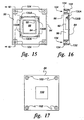
Figure 15 is a top view of the bottom cover shown in Figure 3.
Figure 16 is a cross-sectional view along line 16-16 shown in Figure 15.
Figure 17 is a top view of the current sensor cover shown in Figure 3.
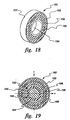
Figure 18 is a perspective view of a self-powered axial current sensor in
accordance with another embodiment of the present invention.
Figure 19 is a cross-sectional view of the current sensor shown in Figure
18.
Figure 20 is a perspective view of the bottom cover of the current sensor
shown in Figure 18.
Figure 21 is an exploded view of the current sensor shown in Figure 18.
Figure 22 illustrates winding the sensing coil on the sensing coil core for
the current sensor shown in Figure 18.
Figure 22a illustrates winding the second layer of a two-layer sensing
coil on the sensing coil core for the current sensor shown in Figure 18.
Figure 23 is a top view of the bottom cover of the current sensor shown
in Figure 20.
Figure 24is a cross-sectional view along line 24-24 shown in Figure 23.
Figure 25 is a top view of the power coil core for the current sensor
shown in Figure 18.
Figure 26 is a cross-sectional view along line 26-26 shown in Figure 25.
Figure 27 is a top view of the current sensor coil core for the current
sensor shown in Figure 27.
Figure 28 is a cross-sectional view along line 28-28 shown in Figure 27.
Figure 1 is a perspective view of a self-powered axial current sensor 50
in accordance with one embodiment of the present invention. Current sensor 50
includes a housing 52 having a bus bar opening 54 extending therethrough. Bus
bar opening 54 is substantially rectangular shaped. Housing 52 is constructed,
e.g., molded, from electrically insulating material such as plastic.
A current sensor core 56 is positioned proximate bus bar opening 54 and
is symmetric about a center axis (not shown) passing longitudinally through
opening 54. Core 56 is formed of four bobbins 58, each having a first end 60
and a second end 62, and each having a substantially rectangular cross-sectional
shape. Each bobbin 58 also has a first flange 64 and a second flange 66. As
described hereinafter in more detail, first and second flanges 64 and 66 include
interlocking members which facilitate arranging bobbins 58 to form core 56.
Bobbins 58 also are constructed from an electrically insulating material such as
plastic.
Current sensor 50 also includes a self-power core 68 positioned
substantially symmetrically with respect to the center axis of opening 54. Self-power
core 68 includes, in one embodiment, separate c-cores 70 held together
by aluminum or other non-magnetic material straps (not shown). C-cores 70
are, for example, formed by a plurality of iron laminations. The C-cores extend
through longitudinal bores (not shown) in power coil bobbins 72, and each
bobbin 72 includes first and second flanges 74 and 76. Bobbins 72 are formed
from electrically insulating material such as plastic.
Figure 2 is a cross-sectional view of current sensor 50 as viewed through
a plane taken along line 2-2 shown in Figure 1, with a bus bar 82 shown
extending through opening 54. Current sensing windings 78 are shown on
current sensing bobbins 58, respectively, and power windings 80 are shown on
power bobbins 72, respectively. Steel laminations of c-cores 70 extending
through bores 84 in power bobbins 72 also are illustrated in Figure 2. The
formation of windings 78 and 80 is described hereinafter in more detail.
Figure 3 is an exploded view of current sensor 50. Sensor 50 includes a
housing 52 having a substantially rectangular-shaped base 84 and cover 86.
Base 84 includes a bus bar opening 88, and retaining walls 90 and 92 are formed
in base 84 and define a current sensor region 94. Walls 90 and 92 facilitate
retaining core 56 in position with respect to bus bar opening 88. Retaining wall
92 and a base wall 96 define a power core region 98. Power core 68 (including
power windings not shown in Figure 2) is located in power coil region 98.
Power core 68 and current sensor core 56 are separated, electrically, by retaining
wall 92. Such separation between power core 68 and current sensing core 56
facilitates preventing electrical interference between self-power core 68 and
current sensing core 56.
Cover 86 includes a bus bar opening 100, and openings 102 in cover 86
align with respective openings 104 in base 84. Threaded bolts (not shown) are
inserted through aligned openings 102 and 104, and threadingly engage with
base openings 104 to maintain cover 86 in engagement with base 84.
Figure 4 illustrates housing base 84 having current sensing core 56 and
power core 68 positioned therein. Cover 86 is not placed over base 84. As
shown in Figure 4, current sensing core 56 is electrically separated from power
core 68. Also, current sensing core 56 and power core 68 are substantially
symmetrical with respect to bus bar opening 88.
Current sensor 50 is shown in a completely assembled configuration in
Figure 5. The power core (not shown) and current sensing core (not shown) are
completely enclosed within housing 52. Bus bar opening 54, formed by
openings 88 (in base 84) and 100 (in cover 86), extends through sensor 50.
Figure 6 is a perspective view of one current sensor coil bobbin 58 used
in the current sensor shown in Figure 1. Bobbin 58, as described above, has a
first end 60 and second end 62, and bobbin 58 has a substantially rectangular
cross sectional shape. Bobbin 58 also includes first and second flanges 64 and
66 as described above, which include interlocking members 106 and 108,
respectively, to facilitate arranging bobbins 58 to form core 56 (Figure 3).
Bobbin 58 also includes an elongate main body member 110.
Figure 7 is a top view of current sensor coil bobbin 58 shown in Figure
6. Interlocking member 106 of first flange 64 is a male type member that
includes a protrusion. Interlocking member 108 of second flange 66 is a female
type member that includes a slot. The slot of each female interlocking member
108 receives an edge of first flange 64 of an adjacent bobbin 58. In this manner,
such interlocking members (e.g., flange 64 and female interlocking member
108) cooperate to retain bobbins 58 configured to form core 56.
Figure 8 is a side view of current sensor coil bobbin 58 shown in Figure
7. As shown in Figure 8, protrusion of male interlocking member 106 extends
the entire length of flange 64. Such configuration facilitates retaining bobbins 58
in the selected configurations.
Figure 9 is a cross section view through line 9-9 shown in Figure 8. As
shown in Figure 9, bobbin 58 has a substantially rectangular cross-sectional
shape and main body member 110 is substantially solid along its length.
Figure 10 illustrates winding of a conductor 112 on current sensor coil
bobbin 58 to form a current sensing coil 114. As shown in Figure 10, main
current sensing winding, or coil, 114 is wound in a clockwise direction around
bobbin 58. A compensating turn winding 116 is placed on bobbin 58 and
extends the longitudinal length of bobbin 58. Main current sensing winding 114
is wound over compensating turn winding 116.
Figure 11 illustrates four (4) wound current sensor coil bobbins 58
arranged to form current sensing core 56. Main current sensing windings 114
on each bobbin 58 are electrically connected in a series aiding arrangement.
Compensating turn windings 116 of each bobbin also are electrically connected
in a series aiding arrangement. Leads 118 extend from sensing core 58 and are
coupled, for example, to an analog to digital converter (not shown) of a digital
integrator circuit.
Figure 12 is a perspective view of one power coil bobbin 72 in current
sensor 50 shown in Figure 1. Bobbin 72 includes first and second substantially
planar flanges 120 and 122, and a main body member 124 having a substantially
rectangular cross-sectional shape. A rectangular shaped opening 126 is formed
in flanges 120 and 122 and a bore (not shown) extends through bobbin 72. The
bore is sized to receive a portion of c-core 70 as illustrated in Figure 1.
Figure 13 is a side view of power coil bobbin 72 shown in Figure 12. As
shown in Figure 13, bore 128 extends through bobbin 72. Power coil windings
(not shown) are wound on bobbin 72 along the length of main body member
124. A conductor, e.g., copper wire, can be used to form such windings.
Figure 14 is a cross-sectional view of power coil bobbin 72 taken along
line 14-14 shown in Figure 13. Bore 128 is aligned with opening 126 in flange
120 and c-core 70 (not shown) extends through bore 128 and openings 126 as
described above.
Figure 15 is a top view of base 84 shown in Figure 3. Base 84 includes
retaining walls 90 and 92 defining current sensor region 94. Protrusions 130A
and 130B formed by retaining wall 92 are used for situating core 56 in the
desired position within current sensor region 94. Specifically, protusions 130
cooperate with male interlocking members 106 of bobbins 58 (Figure 6) to
facilitate positioning core 56 in region 94. Protrusions 130B serve as stops so
that bobbins 58 are supported in region 94 to allow air flow completely around
sensor coils 78.
Figure 16 is a cross-sectional view of base 84 taken along line 16-16
shown in Figure 15. Openings 104 in the base include a first larger diameter
portion 132 and a second smaller diameter portion 134. First larger diameter
portion 132 is sized to receive the head of a threaded bolt so that a bolt does not
extend beyond the periphery of base 84. Also shown in Figure 16 is one
protrusion 130 of retaining wall 92 for positioning core 56 in a desired position.
Figure 17 is a top view of current sensor cover 86 shown in Figure 3.
Openings 102 are sized to receive hex nuts and substantially round bolt heads as
shown. Such arrangement facilitates maintaining cover 86 engaged to base 84.
Current sensor 50 can be used in various applications, such as circuit
breaker applications, at low material and assembly costs. For example, housing
52 and current sensor core 56 are molded, in one embodiment, from a plastic.
Use of such low cost material holds down sensor costs. With respect to
assembly labor, current sensor core 56 and power coil core 68, including their
respective windings, are easily and quickly positioned within housing 52. Cover
86 is then positioned over base 84 and engaged thereto using threaded bolts.
Such ease of assembly facilitates automation of the assembly process and further
enables realization of cost savings.
To monitor current in a power line, the power line is electrically coupled
to a bus bar positioned to extend through bus bar opening 54 in current sensor
50 so that current sensor core 56 and coil 78, and power core 68 and coil 80, are
substantially symmetrical with respect to the bus bar.
The magnetic field generated by current in the bus bar induces a voltage
in current sensor coil 78 and also induces a current in power coil 80. The
induced voltage in current sensor coil 78 is proportional to the time rate of
change of the current in the power conductor and is provided to a sensing circuit
which generates an output signal used for controlling the power system.
The induced current in power coil 80 is used to energize the sensing
circuit components. For example, power coil 80 may be electrically connected to
a power rectifier and control circuit which, in turn, may be connected to supply
power to other components of the unit.
In current sensor 50, the sensing and self-powering functions are
separated so as to facilitate high accuracy current sensing at a low cost. Sensing
core 56, i.e., an air core, can provide increased accuracy, dynamic range,
linearity, and frequency response. In addition, self-power core 68 is a low cost,
saturable, core which prevents overcurrent generation and enables low power
consumption by the breaker unit. Moreover, magnetic cross-talk and magnetic
coupling can be minimized by locating sensing core 56 within self-power core
68.
Since sensing core 56 is symmetric with respect to bus bar 82, accuracy
of sensor 50 is enhanced. Self-power core 68 does not necessarily have to be
symmetric about bus bar 82 to provide the magnetic shielding as described
above. The geometric shape of the sensing core, of course, is not limited to the
rectangular shape described in connection with sensor 50 in order to be
symmetrical with the bus bar since it may be, for example, rectangular,
polygonal, or circular.
Figure 18 is a cross-sectional perspective view of a self-powered axial
current sensor 150 having a circular shape in accordance with another
embodiment of the invention. The sensor includes a housing 152 having a
power line opening 154 of substantially cylindrical shape extending
therethrough. Housing 152 is molded from an electrically insulating material
such as plastic. A toroidal sensing coil core 156 is positioned proximate opening
154 and is symmetric about a center axis (not shown) of opening 154. Sensing
core 156 is formed from a plastic or other insulating material. A toroidal power-up
core 158 having a diameter greater than the diameter of sensing core 156 also
is positioned symmetrically about the center axis of opening 154. Sensing core
156 is separated physically and electrically from power-up core 158 by a
retaining wall 160.
Figure 19 is a cross-sectional front view of current sensor 150 shown in
Figure 18. A power line 162 including a conductor portion 164 and an
insulating portion 166 is shown passing through central power line opening 154.
Current direction (i.e., out of the plane of the page) is indicated on power line
162 by an oncoming arrowhead 169. Cores 156 and 158 are substantially
symmetrically located with respect to power line 162.
Figure 20 is a perspective view of a base 168 of housing 152 including
cores 156 and 158 positioned therein. Base 168 includes sensing coil retaining
rings, or retaining walls, 160 and 170, and a base wall 172. Current sensor core
156 is positioned within a current sensor core region 174 defined by retaining
walls 160 and 170, and power-up core 158 is positioned within a power-up core
region 176 defined by retaining wall 160 and base wall 172. Base 168 also
includes a substantially cylindrical shaped opening 178 extending longitudinally
therethrough.
Figure 21 is an exploded view of current sensor base 168 and cores 156
and 158 shown in Figure 18. As shown in Figure 21, current sensing core 156
is smaller in diameter than power-up core 158. Cores 156 and 158 are easily and
quickly assembled in base 168 by simply locating power-up core 158 in region
176 and locating sensing core 156 in region 174. Although not shown for
simplicity of illustration, a cover is engaged to base 168 with an opening aligned
with opening 178. Optionally, housing 152 can be potted with a suitable epoxy
or silicon compound.
Figure 22 illustrates winding of a current sensing coil 180 on current
sensing core 156. The core material is constructed with a permeability
substantially equal to that of air. Specifically, a conductor 182 is wound around
core 156 over a compensating turn 184, forming coil 180. More specifically, a
compensating turn conductor 184, which has a start end 188, is arranged
circumferentially on core 156, while winding conductor 182 includes a start end
192. Compensating turn conductor 184 is retained under winding conductor
182. As core 156 is rotated clockwise, as indicated by a directional arrow 194,
conductor 182 is wound around core 156 in the path indicated by arrows 196.
Although not illustrated, the power-up coil is formed by wrapping a conductor,
such as a copper conductor, around the power-up core, constructed of magnetic
material, along its length.
The compensating turn 184 is used for the rejection of magnetic fields
that have a component orthogonal to the plane of the windings. The preferred
conStruction of the coil and compensating turn depends upon the number of
layers. In the case of a single layer as shown in Figure 22, the compensating
turn 184 is a single turn of wire laid out on the inside of the coil bobbin. This
compensating turn has the effect of removing the loop corresponding to the
single turn loop that would be created by the loop A-B; otherwise, this loop
would be sensitive to magnetic fields with a component orthogonal to the plane
of the coil. Since there are various stray magnetic fields created by various parts
of the conductors; it is desirable that a compensating turn be used. The area of
the single-turn loop A-B is much larger than the area of the multiple turns created
on the bobbin in order to offset what would otherwise be a noise signal
comparable to the signal obtained from the sensing coil. The compensating turn
is preferably placed in the center of the toroidal cross section at the mean radius,
or at the internal perimeter of the bobbin.
A better compensating turn is obtained in the case of two (or an even
number of) winding layers that are wound in a particular fashion, as shown in
Figure 22a where, for the second layer, the windings are continued in the same
direction around as the first layer, but the bobbin is rotated in a direction 194A
opposite to that of the first layer. This approach guarantees that the signals from
the two winding layers are additive. The second layer automatically forms a
compensating turn 184 since the wire and the connection are again brought to
starting point 188. In this case, however, the compensating turn is much closer
to the windings of the first layer than in the case of a single turn of wire on the
inside perimeter of the bobbin. In the case of two layers thus wound, the
composite effects of pitch advancement are largely nullified.
Figure 23 is a top view of base 168 shown in Figure 20, and includes
current sensing core receiving region 174 and power-up core receiving region
176. Retaining walls 160 and 170 define the periphery of current sensing core
receiving region 174, and retaining wall 160 and base wall 172 define the
periphery of power-up core receiving region 176.
Figure 24 is a cross-sectional view of base 168 taken along line 24-24
shown in Figure 23. As shown in Figure 24, current sensing core receiving
region 174 is separated from power-up core receiving region 176 by wall 170.
Regions 174 and 176 are symmetrical with respect to opening 178.
Figure 25 is a top view of power-up core 158. Power-up core 158 is
substantially ring-shaped and is formed by a plurality of stacked laminations, as
described above, or tape-wound core material. Figure 26 is a cross-sectional
view of power-up core 158 taken along line 26-26 shown in Figure 25. The
core may be coated with suitable insulating material such as epoxy. Winding
197 is situated toroidally about the core to 158 to provide power for electronics
requirements.
Figure 27 is a top view of current sensing core 156. Current sensing
core 156 is substantially ring-shaped and is formed of an insulator, such as a
plastic. Figure 28 is a cross-sectional view of current sensing core 156 taken
along line 28-28 shown in Figure 27. Core 156 is hollow, as shown in Figure
28.
To monitor current in a power line with current sensor 150 (Figure 18),
the power line is passed through power line opening 154, as indicated in Figure
19. When current sensor 150 and the power line are assembled as described
above, current sensing core 156 and coil 180 and power-up core 158 and coil
(not shown) are substantially symmetric with respect to the power line.
In operation, the magnetic field generated by current in the power line
induces a voltage in current sensing coil 180 and also induces a current in the
power-up coil. The induced voltage in current sensing coil 180 is proportional
to the time rate of change of the current in the power conductor, and the current
induced in current sensing coil 180 is provided to a sensing circuit which
generates an output signal used for controlling the power system.
The induced current in the power-up coil is used to energize the sensing
circuit components. For example, the power-up coil may be electrically
connected to a power rectifier and control circuit which, in turn, may be
connected to supply power to other components of the breaker unit.
The above described current sensors can be used in various applications,
such as circuit breaker applications. The current sensors can provide an accurate
signal representative of current in a power conductor, and require relatively low
material and assembly costs. Funher, the current sensors are small and readily
adapted for existing applications.