EP0838246B1 - Post for sports - Google Patents
Post for sports Download PDFInfo
- Publication number
- EP0838246B1 EP0838246B1 EP96932822A EP96932822A EP0838246B1 EP 0838246 B1 EP0838246 B1 EP 0838246B1 EP 96932822 A EP96932822 A EP 96932822A EP 96932822 A EP96932822 A EP 96932822A EP 0838246 B1 EP0838246 B1 EP 0838246B1
- Authority
- EP
- European Patent Office
- Prior art keywords
- fibre
- sports
- post according
- posts
- tube
- Prior art date
- Legal status (The legal status is an assumption and is not a legal conclusion. Google has not performed a legal analysis and makes no representation as to the accuracy of the status listed.)
- Expired - Lifetime
Links
- 239000000835 fiber Substances 0.000 claims abstract description 86
- 239000000463 material Substances 0.000 claims abstract description 45
- 230000007246 mechanism Effects 0.000 claims abstract description 31
- 230000003014 reinforcing effect Effects 0.000 claims abstract description 22
- 229920002430 Fibre-reinforced plastic Polymers 0.000 claims abstract description 20
- 239000011151 fibre-reinforced plastic Substances 0.000 claims abstract description 20
- OKTJSMMVPCPJKN-UHFFFAOYSA-N Carbon Chemical group [C] OKTJSMMVPCPJKN-UHFFFAOYSA-N 0.000 claims abstract description 14
- 229910052799 carbon Inorganic materials 0.000 claims abstract description 14
- 229910052751 metal Inorganic materials 0.000 claims description 21
- 239000002184 metal Substances 0.000 claims description 21
- 229920005989 resin Polymers 0.000 claims description 13
- 239000011347 resin Substances 0.000 claims description 13
- 239000011159 matrix material Substances 0.000 claims description 5
- 229920003023 plastic Polymers 0.000 claims description 3
- 239000004033 plastic Substances 0.000 claims description 3
- 239000004952 Polyamide Substances 0.000 claims description 2
- 239000004372 Polyvinyl alcohol Substances 0.000 claims description 2
- 239000003365 glass fiber Substances 0.000 claims description 2
- 229920002239 polyacrylonitrile Polymers 0.000 claims description 2
- 229920002647 polyamide Polymers 0.000 claims description 2
- 229920000728 polyester Polymers 0.000 claims description 2
- 229920000098 polyolefin Polymers 0.000 claims description 2
- 229920002451 polyvinyl alcohol Polymers 0.000 claims description 2
- 229920001187 thermosetting polymer Polymers 0.000 claims description 2
- 230000014759 maintenance of location Effects 0.000 claims 1
- 238000005452 bending Methods 0.000 abstract description 10
- 230000009467 reduction Effects 0.000 abstract description 7
- 230000000694 effects Effects 0.000 abstract description 5
- 230000000386 athletic effect Effects 0.000 abstract description 4
- 229910000831 Steel Inorganic materials 0.000 description 11
- 238000000034 method Methods 0.000 description 11
- 239000010959 steel Substances 0.000 description 11
- 230000000052 comparative effect Effects 0.000 description 10
- 238000005520 cutting process Methods 0.000 description 9
- 238000004804 winding Methods 0.000 description 8
- 239000011208 reinforced composite material Substances 0.000 description 6
- 239000004411 aluminium Substances 0.000 description 5
- 229910052782 aluminium Inorganic materials 0.000 description 5
- XAGFODPZIPBFFR-UHFFFAOYSA-N aluminium Chemical compound [Al] XAGFODPZIPBFFR-UHFFFAOYSA-N 0.000 description 5
- XEEYBQQBJWHFJM-UHFFFAOYSA-N Iron Chemical compound [Fe] XEEYBQQBJWHFJM-UHFFFAOYSA-N 0.000 description 4
- 238000003780 insertion Methods 0.000 description 4
- 230000037431 insertion Effects 0.000 description 4
- 238000012545 processing Methods 0.000 description 4
- 238000005034 decoration Methods 0.000 description 3
- 239000003822 epoxy resin Substances 0.000 description 3
- 230000006872 improvement Effects 0.000 description 3
- 229920000647 polyepoxide Polymers 0.000 description 3
- 230000002265 prevention Effects 0.000 description 3
- 230000001603 reducing effect Effects 0.000 description 3
- 238000005096 rolling process Methods 0.000 description 3
- 238000010276 construction Methods 0.000 description 2
- 208000028659 discharge Diseases 0.000 description 2
- 230000005484 gravity Effects 0.000 description 2
- 229910052742 iron Inorganic materials 0.000 description 2
- 238000000465 moulding Methods 0.000 description 2
- 238000009987 spinning Methods 0.000 description 2
- 229910001220 stainless steel Inorganic materials 0.000 description 2
- 239000010935 stainless steel Substances 0.000 description 2
- 229920003002 synthetic resin Polymers 0.000 description 2
- 239000000057 synthetic resin Substances 0.000 description 2
- 239000004760 aramid Substances 0.000 description 1
- 229920003235 aromatic polyamide Polymers 0.000 description 1
- 230000015572 biosynthetic process Effects 0.000 description 1
- 230000015556 catabolic process Effects 0.000 description 1
- 230000008859 change Effects 0.000 description 1
- 239000002131 composite material Substances 0.000 description 1
- 238000012790 confirmation Methods 0.000 description 1
- 230000006735 deficit Effects 0.000 description 1
- 238000013461 design Methods 0.000 description 1
- 238000011156 evaluation Methods 0.000 description 1
- 230000001747 exhibiting effect Effects 0.000 description 1
- 238000005087 graphitization Methods 0.000 description 1
- LNEPOXFFQSENCJ-UHFFFAOYSA-N haloperidol Chemical compound C1CC(O)(C=2C=CC(Cl)=CC=2)CCN1CCCC(=O)C1=CC=C(F)C=C1 LNEPOXFFQSENCJ-UHFFFAOYSA-N 0.000 description 1
- 229920006158 high molecular weight polymer Polymers 0.000 description 1
- 238000003475 lamination Methods 0.000 description 1
- 238000004519 manufacturing process Methods 0.000 description 1
- 238000005259 measurement Methods 0.000 description 1
- 239000000025 natural resin Substances 0.000 description 1
- 229920001568 phenolic resin Polymers 0.000 description 1
- 239000005011 phenolic resin Substances 0.000 description 1
- 230000005855 radiation Effects 0.000 description 1
- 230000002787 reinforcement Effects 0.000 description 1
- 239000012783 reinforcing fiber Substances 0.000 description 1
- 230000000087 stabilizing effect Effects 0.000 description 1
- 239000007858 starting material Substances 0.000 description 1
- 230000001629 suppression Effects 0.000 description 1
- 229920006337 unsaturated polyester resin Polymers 0.000 description 1
- 239000013585 weight reducing agent Substances 0.000 description 1
Images


Classifications
-
- A—HUMAN NECESSITIES
- A63—SPORTS; GAMES; AMUSEMENTS
- A63B—APPARATUS FOR PHYSICAL TRAINING, GYMNASTICS, SWIMMING, CLIMBING, OR FENCING; BALL GAMES; TRAINING EQUIPMENT
- A63B61/00—Tennis nets or accessories for tennis or like games, e.g. volley-ball
- A63B61/02—Posts; Revolvably-mounted posts ; Straining or adjusting devices on the posts, e.g. coin- or time operated
-
- A—HUMAN NECESSITIES
- A63—SPORTS; GAMES; AMUSEMENTS
- A63B—APPARATUS FOR PHYSICAL TRAINING, GYMNASTICS, SWIMMING, CLIMBING, OR FENCING; BALL GAMES; TRAINING EQUIPMENT
- A63B61/00—Tennis nets or accessories for tennis or like games, e.g. volley-ball
- A63B61/04—Straining or adjusting devices for nets, e.g. centre strainers, single-double adjusters, net height meters
Definitions
- the present invention relates to sports posts such as net posts, goal posts and posts for athletics, which are light, tough, easily set up and taken down and, moreover, excellent aesthetically.
- US-A-4830382 discloses a portable system for supporting a volleyball net including sports posts made of, for example, aluminium or high strength plastics material which may be reinforced with high strength fibers.
- the sports posts include inner and outer tubes fitted together telescopically. Their respective positions are adjusted manually and they are maintained in their desired relative position by insertion of a retractable plunger pin into respective pairs of apertures in the inner and outer tubes in register with one another.
- the net posts used in volleyball and tennis, and the sports post for soccer, rugby, American football and athletics, etc, have been made of iron or stainless steel metal.
- a post is disclosed in US-A-4 122 451.
- the main structural parts have been made of fairly thick-walled metal from the point of view of strength.
- the general extension/retraction machanism in such posts is usally a system in which two or more hollow tubes are connected by fitting them together telescopically, with the inner tube(s) being raised or lowered by means of a screw mechanism.
- the sports post relating to the present invention are sports posts in which two or more fibre reinforced plastic hollow tubes are fitted and connected together and, moreover, a screw type extension and retraction mechanism is built-in.
- a rod shaped member fixed to one hollow tube passes through the through-hole of an element fixed to one another hollow tube.
- a sports post having at least inner and outer hollow tubes of fibre reinforced plastics material, which tubes are fitted together telescopically, and which sports post additionally has a built in screw type mechanism co-operable with the inner and outer tubes so as to be capable of extension or retraction of the said one tube relative to the other; a rod shaped member fixed relative to one of the inner and outer tubes; and an element fixed relative to the other of the inner and outer tubes and having a through hole through which the rod shaped member passes, whereby on operation of the built in screw type mechanism co-operation between the rod shaped member and the through hole through which the rod shaped member passes prevents rotation of one tube relative to the other and allows the said extension or retraction thereof.
- the hollow tubes of the sports post are composed of a reinforcing fibre layer which comprises a laminate structure of a fibrous sheet material, preferably predominantly sheet material in which the fibre is carbon fibre and filaments thereof are unidirectionally arranged and, more preferably, these sports posts comprise a laminate structure of a filament bundle structure layer which is visible from the outside.
- a filament bundle structure woven materials or a wound filament bundle, etc, are used.
- the present invention is characterised in that the main structural parts of the sports posts are composed of a fibre reinforced plastics material which is light and tough, and while still maintaining the strength to withstand a large bending moment, a considerable reduction in weight is achieved and it is possible to markedly reduce the physical strain at the time of the setting up and taking down of sports posts where frequent such setting up and taking down is required, in particular with net posts for volleyball and tennis.
- the fibre reinforced plastics material referred to in the present invention there can be employed any kind of fibre reinforced plastics material where resin and fibre are combined to achieve a reduction in weight and where the fibre provides the strength but, in terms of the objectives of the present invention, one that provides both lightness and high strength is required.
- a high tenacity fibre of tensile strength desirably at least 20g/d, is desirable. Further, from the need to maintain the post deflection at the same level as that of iron or stainless steel, a high tenacity fibre with a high tensile modulus is used.
- fibre of tensile elastic modulus at least 5,000kgf/mm 2 and, more preferably, at least 20,000kgf/mm 2 .
- high tenacity fibre of still higher elastic modulus for example carbon fibre the tensile elastic modulus of which is raised to a level of 30,000kgf/mm 2 by a graphitization treatment (graphitized fibre), or the like.
- Such fibre is produced according to the factors of material, spinning method and after-processing.
- the fibre material there can be used aromatic polyamide fibres, carbon fibres, glass fibres and light metal fibres, etc.
- fibre spinning methods there can be used fibre spun using a high molecular weight polymer as the starting material, after which drawing is carried out at a high draw ratio, and for fibre after-processing there can be used fibre drawn while exposing to radiation including a plasma discharge.
- polyester fibre polyamide fibre, polyolefin fibre, polyvinyl alcohol fibre and polyacrylonitrile fibre, etc.
- fibres for the purposes of the present invention, from the point of view of the thermal properties when moulding as a composite material there is preferably used a fibre which, along with being of high tenacity and high modulus, also has excellent heat resistance.
- carbon fibre including graphitized fibre
- the chief objective of such fibre is the reinforcement of the post and, consequently, it is preferably combined with the resin in a form and structure such that the properties of the fibre are fully manifested.
- the post be produced using a sheet material comprising the fibre, that is to say at least one type comprising paralleled fibre sheet, woven material or nonwoven material, wound to produce a hollow shape.
- a sheet-wound structure produced by, for example, firstly forming a filament bundle of the fibre into a paralleled fibre sheet-shaped material or into a woven material, and then winding this.
- a hollow wound structure by winding a plurality of layers of the filament bundle directly onto a core without the filament bundle being made in sheet form, which is referred to as a filament-wound structure, and such structures are also desirably employed.
- the fibre reinforced layer may also be constructed by using the two types of structure together.
- the sheet material or filament bundle in order to increase the strength of the posts utilising the tenacity of high tenacity fibre, for at least one of the components in the posts there is preferably employed a structure having a parallel unidirectional arrangement in the circumferential direction of the post, specifically the structure applied to a fishing rod.
- the sheet material or filament bundle is desirably given a discharge treatment or a matrix resin affinity treatment with the objective of improving the adhesion to the resin.
- the reinforcing fibre layer of the outermost layer is a filament bundle structure layer which can be seen from the outside and a transparent resin is used as the matrix resin
- a filament bundle structure is a woven material or filament bundle wound structure and, furthermore, in order that such a structure be visible from the outside, the width of the filament bundle viewed planarly is at least 1mm and, more preferably, at least 2mm.
- specific woven material structures plain weave, twill weave and satin weave are the basic structures, and these and derivative weaves based thereon may be appropriately used according to the decoration required.
- the matrix employed in the fibre reinforced composite material is preferably one of low specific gravity and, for this reason, the use of a resin is preferred.
- the resin there may be used a natural resin, but the use of a high molecular weight synthetic resin is desirable. Of such synthetic resins, the use of a thermosetting resin with outstanding thermal and mechanical properties is preferred.
- thermo-setting resins phenolic resins, epoxy resins or unsaturated polyester resins are desirably employed in terms of toughness and processing characteristics.
- the hollow tubes from which the sports posts are constructed are moulded by means of a fibre reinforced composite material, there is a considerable improvement in particular in terms of lightness when compared to conventional posts made of metal. Furthermore, in terms of bending strength and bending rigidity, the performance conferred is the same as metal posts. However with regard to the mode of failure when an excessive load is applied to the post, there is a strong possibility of differences arising between a metal and a fibre reinforced material.
- the relation between the load and deflection exhibits essentially elastic characteristics up to failure in the case of a fibre reinforced composite material, whereas in the case of a metal, while elastic characteristics are shown up to a certain load, once the yield point has been exceeded the rigidity then falls greatly and plastic deformation characteristics are shown.
- the load countering capacity of both is at the same level, in the case of a metal post a ductile failure mode is displayed whereas with a post of fibre reinforced material a brittle failure mode is shown. Consequently, at the practical level, in the case where an unexpectedly great load is applied to the post, with a metal tube sufficient warning is obtained up to failure occurring, so, in this respect, metal is superior to a fibre reinforced material.
- the production of the hollow tubes from which the sports posts are composed in the form of a hybrid structure of fibre reinforced plastic and metal is more preferred than constructing the post from a fibre reinforced plastic alone.
- the hybrid structure it will suffice that the fibre reinforced material and the metal are closely affixed in layered fashion, and the lamination pattern is not especially restricted.
- a structure in which the metal layer is closely affixed at the hollow tube inner layer side is preferred.
- a hollow tube by means of a fibre reinforced composite material, there is conducted the winding of a sheet material or filament bundle of said fibre as explained above and, in such circumstances, the winding is performed using a metal rod known as a mandrel as the core.
- a metal rod known as a mandrel as the core.
- a hollow tube made of metal is used instead of this mandrel then, as well as it being possible to dispense with the normally required stage of withdrawing the mandrel, it is also possible to obtain the desired hybrid structure.
- the material for this metal-made hollow tube is not particularly restricted but, for the purposes of reducing the weight, the selection of a metal of low specific gravity such as aluminium is preferred.
- the wall thickness needs to be decided based on a balance between the weight reducing effect and the brittle failure prevention effect, and this will vary according to the diameter of the hollow tube and the type of metal used. However, a lower limit of wall thickness is required sufficient to withstand the pressure of the triple-roll or the rolling table, etc, in the reinforcing fibre sheet material winding stage.
- the extension/retraction mechanism of the present invention is now explained based on the drawings.
- the extension/retraction mechanism of the present invention is a system whereby, to a nut portion provided on one inner tube, there is fitted the bolt of a bolt rotation mechanism provided on the inside of another outer tube, and by rotating the bolt of this bolt rotation mechanism via a bevel gear, the said inner tube is raised or lowered, but the characteristics feature lies in the fact that co-rotation is prevented by passing a rod shaped member fixed to the said one hollow tube through a through-hole fixed in the other hollow tube.
- Figure 1 is a view of the entire structure of a net post for volleyball to which the present invention has been applied
- Figure 2 is a cross-sectional view showing the raising/lowering mechanism in the interior.
- An outer tube 1 and an inner tube 2 are fitted and connected together in the manner of a telescope or aerial.
- the post height is adjusted by raising or lowering the inner tube.
- a bolt rotation mechanism is used in which, firstly, a handle 4 used for raising/lowering is inserted into a handle insertion hole 3 provided in the outer tube wall and the rotation thereof is transmitted to a bevel gear 5.
- the axis of rotation is made to change direction so that it matches the tube axis, while simultaneously the rotation is transmitted to raising/lowering screw bolt 6 which is internally fixed in the outer tube 1.
- raising/lowering screw nut 7 which is cooperable with the raising/lowering screw bolt 6, and inner tube 2 is raised or lowered according to the direction of the screw bolt 6.
- a characteristic feature of the present invention lies in the mechanism for preventing the co-rotation of the raising/lowering screw nut 7. That is to say, internal screw-based extension/retraction is only possible by suppressing rotation of the screw nut 7, but naturally this suppression of rotation must not inhibit the raising/lowering movement of the inner tube 2. Accordingly, in a conventional net post made of steel, a lead-in groove is cut into the surface of the inner tube 2, running in the tube axial direction, and a key which has been provided in the outer tube fits into this lead-in groove, so that by the movement of this key within the lead-in groove co-rotation is prevented without obstructing the extension/ retraction.
- the co-rotation of the raising/lowering screw nut is prevented by a completely different method from this conventional mechanism. That is to say, there is employed a mechanism whereby a rod shaped member fixed to one hollow tube passes through the through hole of an element fixed to another hollow tube.
- rod shaped member 8 is fixed to raising/lowering nut 7 such that it is parallel to but does not touch raising/lowering screw bolt 6 and, furthermore, this rod shaped member 8 passes through lead-in hole 10 provided in raising/lowering screw bolt fixture 9 which is fixed within the outer tube.
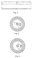
- Figure 3 shows an example of the rod shaped member (an L-shaped bar) used in the present invention.
- Figure 4 is a sectional view through A-A in Figure 2, and shows the L-shaped bar in Figure 3 bolted to raising/lowering screw nut 7.
- Figure 5 is a sectional view through B-B in Figure 2 and shows the L-shaped bar suspended from raising/lowering screw nut 7 passing through the lead-in hole 10 provided in raising/ lowering screw bolt fixture 9.
- this rod shaped member 8 passes freely up and down through lead-in hole 10, merely preventing co-rotation of the screw nut.
- the rod shaped member 8 may be of any shape such as a circular or angular column, but it is necessary that it be straight and without differences in level, grooves or projections, etc, which would inhibit movement in its lengthwise direction.
- the material of the rod shaped member is not particularly restricted providing it has a strength and stiffness such that breakdown or large distortions do not occur when preventing the co-rotation.
- the improvement effect in terms of the strength properties of a net post based on the structure according to the present invention will differ considerably depending on the tube material.
- the tube material used is a fibre reinforced plastic for the purposes of weight reduction, then the improvement effect in this respect is very considerable compared to a steel product.
- the sports posts of the present invention can also be used for example as posts for supporting nets such as those for golf practice ranges and baseball grounds, etc, where it is important that they be strong and light, and where they also have the considerable feature that setting up and taking down is easy.
- the sports posts referred to in the present invention include net posts for volleyball, tennis, badminton, golf, baseball and table tennis, goal posts for soccer, rugby, American football, handball and hockey, and also the various kinds of posts and frameworks such as hurdles used in athletics, etc.
- the sports posts of the present invention are employed as the various kinds of posts for ball games in multi-purpose locations like gymnasia where the setting up and taking down of said posts is frequently carried out, then the effects in terms of reducing the physical effort at the time of such setting up and taking down of the posts are markedly apparent.
- the net posts for sports in the present invention can be employed widely for games and sports conducted both indoors and outdoors, and include rod shapes and frameworks.
- providing the tubes are hollow, the cross-sectional shape of such tubes does not have to be circular and can be changed to be elliptical, angular, etc, according to the usage objectives, and it is possible to construct various types of apparatus employed in games and sports.
- the extending/retracting net post shown in Figure 1 was constructed as a net post for volleyball.
- the hollow tubes forming the main structural members of the net post comprised fibre reinforced plastics material in which carbon fibre filament was the reinforcing fibre.
- carbon fibre filament there was selected a high modulus type of strength 40g/d and tensile modulus 30,000 kgf/mm 2
- sheet prepreg in which epoxy resin was the matrix was moulded in the form of tubes of wall thickness 6.0mm by a sheet winding method.
- the rolling table method was selected and, as the laminate pattern, unidirectional prepreg was oriented at 0° and ⁇ 45° to the circumferential direction and a strengthwise balance obtained.
- the number of plies in each direction was determined such that the 0° and ⁇ 45° balance ratio was set at 4 : 1.
- a 5-end satin weave sheet was employed for decoration in the outermost layer. These sheet prepregs were firstly laid-up by wrapping around a mandrel while applying a pressure of 3kg/cm 2 with a rolling table and then wrapping tape wound around, after which curing was carried out at 130°C in a curing oven and, finally, the mandrel withdrawn.
- a net post was constructed having a screw type raising and lowering mechanism of the same kind as in conventional steel posts.
- hollow tubes of wall thickness 6.0 mm in which the reinforcing fibre was carbon fibre filament were moulded by an identical method to that in Example 1, but the outer face of the inner tube was cut to form a groove of depth 3.0mm and width 5.0mm continuously in the lengthwise direction.
- a key to fit this groove was provided at the inner wall portion of the outer tube tip, and then the net post assembled with this key fitted into the groove in the outer wall of the inner tube.
- the wall thickness of the tubes was 5.2mm.
- Hollow tubes were moulded by the sheet winding method using carbon fibre filament as the reinforcing fibre in the same way as in Example 1, but instead of the mandrel an aluminium tube of wall thickness 1.0mm was used as the core, and a laminate structure of aluminium and a carbon fibre reinforced resin layer obtained.
- the adhered state of the aluminium and the fibre reinforced resin layer was sufficient for practical purposes, and there was no particular need to use a primer or the like.
- the total wall thickness of the hollow tube obtained was made 6.0mm, the same as in Example 1, and the internal raising and lowering mechanism was also the same.
- Table 1 shows the results of an evaluation of the operation of the raising and lowering device in these net posts and of the bending characteristics of the hollow tubes.
- the operation of the raising and lowering device was judged based on the resistance when turning the raising and lowering handle by hand without introducing wire tension.
- the bending characteristics reference was made to the Recognised Standards Confirmation Method relating to safety and quality of volleyball equipment as stipulated by the Product Safety Committee. Firstly, in a state such that the post height was held at 2430mm, an initial tension of 50kgf was introduced and the net extended and stabilised for at least one minute. Next, taking this state as the standard, a further 200kgf load was applied and after stabilizing by holding for at least one minute, the level of post deflection was measured by means of a scale. According to the Recognised Standard of the Product Safety Committee, when a load of 250kgf is applied to a post made of steel, the deflection must be no more than 130mm.
- the volleyball net posts based on the present invention were made of carbon fibre reinforced plastic and so, when contrasted with Comparative Example 2 which was a conventional steel net post, the weight was less than 1/3, and not just the carrying of the posts at the time of setting up and taking down but also the operation of the raising and lowering device was light and easy.
- Comparative Example 1 which was made of the same carbon fibre reinforced plastic and only the raising/lowering mechanism was the same as in a conventional steel post, while there was no difference in the ease of operation, the level of deflection of the post when the tension was applied was greater than that in Example 1 and Comparative Example 2 when tension was applied. In order to avoid any danger, measurement was halted at the point when the deflection exceeded 200mm.
- Example 2 While the weight and deflection were slightly increased, the operational characteristics of the raising/lowering device were no different when compared to Example 1 and, in practical terms, the difference in weight and deflection were such as to be hardly noticed.
- Example 2 Tube diameter (external diameter of outer tube) 76.3mm 76.3mm 76.3mm 76.3mm Tube wall thickness 6.0cm 6.0cm 5.2cm 6.0cm Weight (per set) 20.8kg 20.7kg 71.4kg 22.4kg Raising/lowering operational characteristics o ⁇ o ⁇ ⁇ o ⁇ Level of defection (tension 250kgf) 118.4mm above 200mm 115.8mm 128.2mm
- the weight includes the pulley portion, wire take-up portion and the screw bolt/nut for raising lowering, etc.
Landscapes
- Health & Medical Sciences (AREA)
- General Health & Medical Sciences (AREA)
- Physical Education & Sports Medicine (AREA)
- Golf Clubs (AREA)
- Laminated Bodies (AREA)
- Steering Devices For Bicycles And Motorcycles (AREA)
- Orthopedics, Nursing, And Contraception (AREA)
- Magnetic Treatment Devices (AREA)
- Superconductors And Manufacturing Methods Therefor (AREA)
- Separation By Low-Temperature Treatments (AREA)
- Particle Accelerators (AREA)
- Professional, Industrial, Or Sporting Protective Garments (AREA)
- Moulding By Coating Moulds (AREA)
Abstract
Description
- 1 :
- outer tube
- 2 :
- inner tube
- 3 :
- handle insertion hole
- 4 :
- raising/lowering handle
- 5 :
- bevel gear
- 6 :
- raising/lowering screw bolt
- 7 :
- raising/lowering screw nut
- 8 :
- rod shaped member
- 9 :
- raising/lowering screw bolt fixture
- 10 :
- lead-in hole
| Example 1 | Comparative Example 1 | Comparative Example 2 | Example 2 | |
| Tube diameter (external diameter of outer tube) | 76.3mm | 76.3mm | 76.3mm | 76.3mm |
| Tube wall thickness | 6.0cm | 6.0cm | 5.2cm | 6.0cm |
| Weight (per set) | 20.8kg | 20.7kg | 71.4kg | 22.4kg |
| Raising/lowering operational characteristics | o ○ | o ○ | ○ | o ○ |
| Level of defection (tension 250kgf) | 118.4mm | above 200mm | 115.8mm | 128.2mm |
| Note: The weight includes the pulley portion, wire take-up portion and the screw bolt/nut for raising lowering, etc. |
Claims (19)
- A sports post having at least inner (2) and outer (1) hollow tubes of fibre reinforced plastics material, which tubes (1),(2) are fitted together telescopically, and which sports post additionally has (a) a built in screw type mechanism co-operable with the inner and outer tubes (1), (2) so as to be capable of extension or retraction of one said tube relative to the other; (b) a rod shaped member (8) fixed relative to one of the inner and outer tubes (1),(2); and (c) an element (9) fixed relative to the other of the inner and outer tubes (1),(2) and having a through hole (10) through which the rod shaped member (8) passes, whereby on operation of the built in screw type mechanism co-operation between the rod shaped member (8) and the through hole (10) through which the rod shaped member (8) passes prevents rotation of one tube (1) or (2) relative to the other (2) or (1) and allows the said extension.or retraction thereof.
- A sports post according to claim 1, wherein the rod shaped member (8) is fixed relative to the inner tube (2) and the element (9) having the through hole (10) is fixed relative to and extends across the outer tube (1), the inner tube (2) having, fixed thereto and disposed therein, a screw nut (7) having a threaded aperture coaxial with the inner tube (2) and cooperable with a screw bolt (6) of the screw type mechanism, the rod shaped member (8) being fixed to the screw nut (7) such that the rod shaped member (8) is parallel to but does not touch the screw bolt (6) and passes through the through hole (10) in the element (9) extending across the outer tube (1), whereby, on rotation of the screw bolt (6) for axial movement of the inner tube (2) relative to the outer tube (1), corotation with the screw bolt (6) of the screw nut (7) and therefore the inner tube (2) to which the screw nut (7) is fixed is prevented by retention of the rod shaped member (8) within the through hole (10) in element (9).
- A sports post according to claim 1 or claim 2, wherein the hollow tubes (1),(2) are composed of a reinforcing fibre layer which comprises primarily a laminate structure of fibrous sheet material.
- A sports post according to claim 3, wherein the fibrous sheet material is of at least one type selected from a sheet material in which filament is unidirectionally arranged, woven materials and nonwoven materials.
- A sports post according to claim 3, wherein the reinforcing fibre layer comprises a laminate structure of a sheet material in which filament is unidirectionally arranged and a filament bundle structure layer which is visible from the outside.
- A sports post according to claim 5, wherein the filament bundle structure layer is a woven material.
- A sports post according to claim 5, wherein the filament bundle structure layer is a filament bundle wound layer.
- A sports post according to claim 1 or claim 2, wherein the hollow tubes are composed of a reinforcing fibre layer which is a filament bundle wound layer.
- A sports post according to any one of claims 5 to 8, wherein the width of the filament bundle viewed planarly is at least 1 mm.
- A sports post according to claim 9, wherein the width of the filament bundle viewed planarly is at least 2 mm.
- A sports post according to any one of the preceding claims, wherein the strength of the reinforcing fibre is at least 20g/d.
- A sports post according to any one of the preceding claims, wherein the tensile elastic modulus of the reinforcing fibre is at least 5,000kgf/mm2.
- A sports post according to claim 12, wherein the tensile elastic modulus of the reinforcing fibre is at least 20,000kgf/mm2.
- A sports post according to any one of the preceding claims, wherein the reinforcing fibre is of at least one type selected from polyester fibre, polyamide fibre, polyolefin fibre, polyvinyl alcohol fibre, polyacrylonitrile fibre, light metal fibre, carbon fibre and glass fibre.
- A sports post according to any one of the preceding claims, wherein the reinforcing fibre is carbon fibre.
- A sports post according to any one of the preceding claims, the hollow tubes (1),(2) of which have a higher elastic modulus in an outer region, provided by reinforcing fibre, than in an inner region.
- A sports post according to any one of the preceding claims, wherein the hollow tubes (1),(2) of fibre reinforced plastics material are of a hybrid structure in which respective layers of the fibre reinforced plastics material and metal are closely affixed.
- A sports post according to claim 17, wherein the metal layer is arranged as an innermost layer of each hollow tube.
- A sports post according to any one of the preceding claims, wherein the plastics material of each hollow tube is a transparent thermosetting matrix resin.
Applications Claiming Priority (7)
| Application Number | Priority Date | Filing Date | Title |
|---|---|---|---|
| JP9388796 | 1996-04-16 | ||
| JP93887/96 | 1996-04-16 | ||
| JP9388796A JPH09276460A (en) | 1996-04-16 | 1996-04-16 | Telescopic net support |
| JP12825896 | 1996-05-23 | ||
| JP12825896A JPH0960346A (en) | 1995-06-12 | 1996-05-23 | Sports posts and flag hoisting towers and flags and clothes poles |
| JP128258/96 | 1996-05-23 | ||
| PCT/JP1996/002899 WO1997038761A1 (en) | 1996-04-16 | 1996-10-04 | Post for sports |
Publications (3)
| Publication Number | Publication Date |
|---|---|
| EP0838246A1 EP0838246A1 (en) | 1998-04-29 |
| EP0838246A4 EP0838246A4 (en) | 2002-08-28 |
| EP0838246B1 true EP0838246B1 (en) | 2004-12-22 |
Family
ID=26435163
Family Applications (1)
| Application Number | Title | Priority Date | Filing Date |
|---|---|---|---|
| EP96932822A Expired - Lifetime EP0838246B1 (en) | 1996-04-16 | 1996-10-04 | Post for sports |
Country Status (7)
| Country | Link |
|---|---|
| US (1) | US6030301A (en) |
| EP (1) | EP0838246B1 (en) |
| KR (1) | KR100481751B1 (en) |
| AT (1) | ATE285275T1 (en) |
| DE (1) | DE69634087T2 (en) |
| TW (1) | TW378158B (en) |
| WO (1) | WO1997038761A1 (en) |
Cited By (1)
| Publication number | Priority date | Publication date | Assignee | Title |
|---|---|---|---|---|
| US9266005B2 (en) | 2012-05-31 | 2016-02-23 | Stonesnet Ab | Net with a vertically adjustable upper edge for a playing area and a method for adjusting the height of the upper edge |
Families Citing this family (8)
| Publication number | Priority date | Publication date | Assignee | Title |
|---|---|---|---|---|
| US7235025B2 (en) * | 2005-04-14 | 2007-06-26 | Hockey Western New York, Llc | Sports goal having curvilinear frame section |
| US7410431B2 (en) * | 2006-05-18 | 2008-08-12 | Sports Imports, Inc. | Composite locking upright |
| US8113971B2 (en) * | 2006-05-18 | 2012-02-14 | Sports Imports, Inc. | Multi-material composite locking upright |
| US7559860B2 (en) * | 2006-05-18 | 2009-07-14 | Sports Imports, Inc. | Multi-material composite locking upright |
| CN102363071A (en) * | 2011-10-19 | 2012-02-29 | 姜振良 | Badminton training device |
| US10549139B2 (en) | 2014-02-25 | 2020-02-04 | W2Designs Llc | Isometric exercise and stretching apparatus |
| US9545551B1 (en) * | 2014-09-13 | 2017-01-17 | Joe Dinoffer | Net and frame assemblies for net and wall games |
| CN104548535B (en) * | 2015-01-16 | 2016-09-28 | 江苏金陵体育器材股份有限公司 | The pre-buried angle of volleyball post and direction adjustment device |
Family Cites Families (15)
| Publication number | Priority date | Publication date | Assignee | Title |
|---|---|---|---|---|
| JPS4515540Y1 (en) * | 1967-12-30 | 1970-06-29 | ||
| JPS49112189U (en) * | 1973-01-30 | 1974-09-25 | ||
| JPS51135645U (en) * | 1975-04-23 | 1976-11-02 | ||
| US4122451A (en) * | 1976-10-29 | 1978-10-24 | Senoh Kabushiki Kaisha | Net post suitable for use in ball games |
| JPS5870267U (en) * | 1981-11-06 | 1983-05-12 | 黒木 清隆 | Ball game prop |
| US4830382A (en) * | 1988-12-09 | 1989-05-16 | Outaboundz Usa Inc. | Portable volleyball net support system |
| JPH03272784A (en) * | 1990-03-23 | 1991-12-04 | T N Net Kk | Net prop for playing court |
| DE4105777A1 (en) * | 1990-06-07 | 1991-12-12 | Michael Imhof | Sports practice net with high stiffness - is useful for tennis or badminton training |
| US5215310A (en) * | 1992-01-22 | 1993-06-01 | Allbright Edwin T | Volleyball net support and tensioning system |
| US5242174A (en) * | 1992-10-16 | 1993-09-07 | Schelde International B.V. | Game net post and a horizontal bar post as well as storing systems therefor |
| US5308085A (en) * | 1993-05-19 | 1994-05-03 | Scheide International B.V. | Game net post |
| US5358257A (en) * | 1993-09-10 | 1994-10-25 | Jayfro Corporation | Volleyball game net |
| US5393069A (en) * | 1994-02-25 | 1995-02-28 | Eugene V. Hearl | Retractable backboard suspended not support |
| JP3011041U (en) * | 1994-11-10 | 1995-05-16 | 福井漁網株式会社 | Soccer goal and its net frame |
| JP3021296U (en) * | 1995-08-04 | 1996-02-20 | 宇部日東化成株式会社 | Goal net frame for ball games |
-
1996
- 1996-04-10 US US08/981,414 patent/US6030301A/en not_active Expired - Fee Related
- 1996-10-04 AT AT96932822T patent/ATE285275T1/en not_active IP Right Cessation
- 1996-10-04 WO PCT/JP1996/002899 patent/WO1997038761A1/en not_active Ceased
- 1996-10-04 KR KR1019970708937A patent/KR100481751B1/en not_active Expired - Fee Related
- 1996-10-04 EP EP96932822A patent/EP0838246B1/en not_active Expired - Lifetime
- 1996-10-04 DE DE69634087T patent/DE69634087T2/en not_active Expired - Fee Related
-
1997
- 1997-07-19 TW TW086110260A patent/TW378158B/en not_active IP Right Cessation
Cited By (2)
| Publication number | Priority date | Publication date | Assignee | Title |
|---|---|---|---|---|
| US9266005B2 (en) | 2012-05-31 | 2016-02-23 | Stonesnet Ab | Net with a vertically adjustable upper edge for a playing area and a method for adjusting the height of the upper edge |
| USD800859S1 (en) | 2012-05-31 | 2017-10-24 | Stonesnet Ab | Pole for adjustable net |
Also Published As
| Publication number | Publication date |
|---|---|
| DE69634087D1 (en) | 2005-01-27 |
| DE69634087T2 (en) | 2006-01-19 |
| WO1997038761A1 (en) | 1997-10-23 |
| EP0838246A4 (en) | 2002-08-28 |
| EP0838246A1 (en) | 1998-04-29 |
| KR19990022456A (en) | 1999-03-25 |
| ATE285275T1 (en) | 2005-01-15 |
| TW378158B (en) | 2000-01-01 |
| US6030301A (en) | 2000-02-29 |
| KR100481751B1 (en) | 2005-12-08 |
Similar Documents
| Publication | Publication Date | Title |
|---|---|---|
| US5048441A (en) | Composite sail mast with high bending strength | |
| US6761653B1 (en) | Composite wrap bat with alternative designs | |
| US5303916A (en) | Hockey stick shaft | |
| US6273830B1 (en) | Tapered hollow shaft | |
| US6030301A (en) | Sports posts | |
| US5549947A (en) | Composite shaft structure and manufacture | |
| USRE35081E (en) | Composite structural member with high bending strength | |
| US5419553A (en) | Hockey stick shaft | |
| US6306474B1 (en) | Hybrid fiber-reinforced plastic | |
| GB2326103A (en) | Fibre-reinforced shaft | |
| US5633074A (en) | Prepreg available for fiber reinforced thermoplastic resin and process of producing sporting goods using the same | |
| US4995246A (en) | Warp knitting machine with at least one bar | |
| JPWO1998047693A1 (en) | Hybrid fiber reinforced plastic | |
| EP0072256A2 (en) | Reinforced fabric | |
| JP2003024489A (en) | Golf club shaft | |
| CA2224787C (en) | Sports posts | |
| KR100298101B1 (en) | Fiber Reinforced Composite Material | |
| JPH09276460A (en) | Telescopic net support | |
| US20040102115A1 (en) | Laminar reinforcing structure for impact resisting face on an article | |
| CN1188421A (en) | Post for sports | |
| CA2125343C (en) | Hockey stick shaft | |
| JP3257238B2 (en) | Fiber reinforced plastic cylinder | |
| CN114654763B (en) | Manufacturing process of middle tube of badminton racket and middle tube of badminton racket | |
| CA2216508A1 (en) | Sporting equipment constructed with composite materials having composite rods interspersed with bias plies | |
| US11045677B1 (en) | Vaulting pole |
Legal Events
| Date | Code | Title | Description |
|---|---|---|---|
| PUAI | Public reference made under article 153(3) epc to a published international application that has entered the european phase |
Free format text: ORIGINAL CODE: 0009012 |
|
| 17P | Request for examination filed |
Effective date: 19980113 |
|
| AK | Designated contracting states |
Kind code of ref document: A1 Designated state(s): AT BE CH DE DK ES FI FR GB GR IE IT LI NL PT SE |
|
| A4 | Supplementary search report drawn up and despatched |
Effective date: 20020717 |
|
| AK | Designated contracting states |
Kind code of ref document: A4 Designated state(s): AT BE CH DE DK ES FI FR GB GR IE IT LI NL PT SE |
|
| 17Q | First examination report despatched |
Effective date: 20030718 |
|
| GRAP | Despatch of communication of intention to grant a patent |
Free format text: ORIGINAL CODE: EPIDOSNIGR1 |
|
| GRAJ | Information related to disapproval of communication of intention to grant by the applicant or resumption of examination proceedings by the epo deleted |
Free format text: ORIGINAL CODE: EPIDOSDIGR1 |
|
| GRAP | Despatch of communication of intention to grant a patent |
Free format text: ORIGINAL CODE: EPIDOSNIGR1 |
|
| GRAS | Grant fee paid |
Free format text: ORIGINAL CODE: EPIDOSNIGR3 |
|
| GRAA | (expected) grant |
Free format text: ORIGINAL CODE: 0009210 |
|
| AK | Designated contracting states |
Kind code of ref document: B1 Designated state(s): AT BE CH DE DK ES FI FR GB GR IE IT LI NL PT SE |
|
| PG25 | Lapsed in a contracting state [announced via postgrant information from national office to epo] |
Ref country code: NL Free format text: LAPSE BECAUSE OF FAILURE TO SUBMIT A TRANSLATION OF THE DESCRIPTION OR TO PAY THE FEE WITHIN THE PRESCRIBED TIME-LIMIT Effective date: 20041222 Ref country code: LI Free format text: LAPSE BECAUSE OF FAILURE TO SUBMIT A TRANSLATION OF THE DESCRIPTION OR TO PAY THE FEE WITHIN THE PRESCRIBED TIME-LIMIT Effective date: 20041222 Ref country code: FI Free format text: LAPSE BECAUSE OF FAILURE TO SUBMIT A TRANSLATION OF THE DESCRIPTION OR TO PAY THE FEE WITHIN THE PRESCRIBED TIME-LIMIT Effective date: 20041222 Ref country code: CH Free format text: LAPSE BECAUSE OF FAILURE TO SUBMIT A TRANSLATION OF THE DESCRIPTION OR TO PAY THE FEE WITHIN THE PRESCRIBED TIME-LIMIT Effective date: 20041222 Ref country code: BE Free format text: LAPSE BECAUSE OF FAILURE TO SUBMIT A TRANSLATION OF THE DESCRIPTION OR TO PAY THE FEE WITHIN THE PRESCRIBED TIME-LIMIT Effective date: 20041222 Ref country code: AT Free format text: LAPSE BECAUSE OF FAILURE TO SUBMIT A TRANSLATION OF THE DESCRIPTION OR TO PAY THE FEE WITHIN THE PRESCRIBED TIME-LIMIT Effective date: 20041222 |
|
| REG | Reference to a national code |
Ref country code: GB Ref legal event code: FG4D |
|
| REG | Reference to a national code |
Ref country code: CH Ref legal event code: EP |
|
| REG | Reference to a national code |
Ref country code: IE Ref legal event code: FG4D |
|
| REF | Corresponds to: |
Ref document number: 69634087 Country of ref document: DE Date of ref document: 20050127 Kind code of ref document: P |
|
| PG25 | Lapsed in a contracting state [announced via postgrant information from national office to epo] |
Ref country code: SE Free format text: LAPSE BECAUSE OF FAILURE TO SUBMIT A TRANSLATION OF THE DESCRIPTION OR TO PAY THE FEE WITHIN THE PRESCRIBED TIME-LIMIT Effective date: 20050322 Ref country code: GR Free format text: LAPSE BECAUSE OF FAILURE TO SUBMIT A TRANSLATION OF THE DESCRIPTION OR TO PAY THE FEE WITHIN THE PRESCRIBED TIME-LIMIT Effective date: 20050322 Ref country code: DK Free format text: LAPSE BECAUSE OF FAILURE TO SUBMIT A TRANSLATION OF THE DESCRIPTION OR TO PAY THE FEE WITHIN THE PRESCRIBED TIME-LIMIT Effective date: 20050322 |
|
| PG25 | Lapsed in a contracting state [announced via postgrant information from national office to epo] |
Ref country code: ES Free format text: LAPSE BECAUSE OF FAILURE TO SUBMIT A TRANSLATION OF THE DESCRIPTION OR TO PAY THE FEE WITHIN THE PRESCRIBED TIME-LIMIT Effective date: 20050402 |
|
| NLV1 | Nl: lapsed or annulled due to failure to fulfill the requirements of art. 29p and 29m of the patents act | ||
| REG | Reference to a national code |
Ref country code: CH Ref legal event code: PL |
|
| PG25 | Lapsed in a contracting state [announced via postgrant information from national office to epo] |
Ref country code: IE Free format text: LAPSE BECAUSE OF NON-PAYMENT OF DUE FEES Effective date: 20051004 |
|
| ET | Fr: translation filed | ||
| PLBE | No opposition filed within time limit |
Free format text: ORIGINAL CODE: 0009261 |
|
| STAA | Information on the status of an ep patent application or granted ep patent |
Free format text: STATUS: NO OPPOSITION FILED WITHIN TIME LIMIT |
|
| 26N | No opposition filed |
Effective date: 20050923 |
|
| REG | Reference to a national code |
Ref country code: IE Ref legal event code: MM4A |
|
| PG25 | Lapsed in a contracting state [announced via postgrant information from national office to epo] |
Ref country code: PT Free format text: LAPSE BECAUSE OF NON-PAYMENT OF DUE FEES Effective date: 20050522 |
|
| PGFP | Annual fee paid to national office [announced via postgrant information from national office to epo] |
Ref country code: DE Payment date: 20070927 Year of fee payment: 12 |
|
| PGFP | Annual fee paid to national office [announced via postgrant information from national office to epo] |
Ref country code: IT Payment date: 20071027 Year of fee payment: 12 |
|
| PGFP | Annual fee paid to national office [announced via postgrant information from national office to epo] |
Ref country code: GB Payment date: 20071003 Year of fee payment: 12 Ref country code: FR Payment date: 20071009 Year of fee payment: 12 |
|
| GBPC | Gb: european patent ceased through non-payment of renewal fee |
Effective date: 20081004 |
|
| REG | Reference to a national code |
Ref country code: FR Ref legal event code: ST Effective date: 20090630 |
|
| PG25 | Lapsed in a contracting state [announced via postgrant information from national office to epo] |
Ref country code: IT Free format text: LAPSE BECAUSE OF NON-PAYMENT OF DUE FEES Effective date: 20081004 Ref country code: DE Free format text: LAPSE BECAUSE OF NON-PAYMENT OF DUE FEES Effective date: 20090501 |
|
| PG25 | Lapsed in a contracting state [announced via postgrant information from national office to epo] |
Ref country code: FR Free format text: LAPSE BECAUSE OF NON-PAYMENT OF DUE FEES Effective date: 20081031 |
|
| PG25 | Lapsed in a contracting state [announced via postgrant information from national office to epo] |
Ref country code: GB Free format text: LAPSE BECAUSE OF NON-PAYMENT OF DUE FEES Effective date: 20081004 |