EP0837440B1 - A magnetic head for a magnetic display - Google Patents
A magnetic head for a magnetic display Download PDFInfo
- Publication number
- EP0837440B1 EP0837440B1 EP19970308356 EP97308356A EP0837440B1 EP 0837440 B1 EP0837440 B1 EP 0837440B1 EP 19970308356 EP19970308356 EP 19970308356 EP 97308356 A EP97308356 A EP 97308356A EP 0837440 B1 EP0837440 B1 EP 0837440B1
- Authority
- EP
- European Patent Office
- Prior art keywords
- magnetic
- diameter
- air gap
- magnetic core
- edge
- Prior art date
- Legal status (The legal status is an assumption and is not a legal conclusion. Google has not performed a legal analysis and makes no representation as to the accuracy of the status listed.)
- Expired - Lifetime
Links
- 239000003094 microcapsule Substances 0.000 claims description 19
- 239000006247 magnetic powder Substances 0.000 claims description 4
- 230000008878 coupling Effects 0.000 claims description 2
- 238000010168 coupling process Methods 0.000 claims description 2
- 238000005859 coupling reaction Methods 0.000 claims description 2
- 230000004907 flux Effects 0.000 description 25
- 239000006249 magnetic particle Substances 0.000 description 15
- 230000005389 magnetism Effects 0.000 description 13
- 238000006243 chemical reaction Methods 0.000 description 11
- 239000007788 liquid Substances 0.000 description 9
- 239000002245 particle Substances 0.000 description 7
- 230000007423 decrease Effects 0.000 description 6
- 239000011159 matrix material Substances 0.000 description 5
- 239000002775 capsule Substances 0.000 description 3
- 239000011247 coating layer Substances 0.000 description 3
- 239000000463 material Substances 0.000 description 3
- 238000013459 approach Methods 0.000 description 2
- 239000003086 colorant Substances 0.000 description 2
- 230000035699 permeability Effects 0.000 description 2
- -1 polyethylene terephthalate Polymers 0.000 description 2
- 239000012780 transparent material Substances 0.000 description 2
- 239000004925 Acrylic resin Substances 0.000 description 1
- 229920000178 Acrylic resin Polymers 0.000 description 1
- 108010010803 Gelatin Proteins 0.000 description 1
- 239000004743 Polypropylene Substances 0.000 description 1
- GWEVSGVZZGPLCZ-UHFFFAOYSA-N Titan oxide Chemical compound O=[Ti]=O GWEVSGVZZGPLCZ-UHFFFAOYSA-N 0.000 description 1
- 239000000853 adhesive Substances 0.000 description 1
- 230000001070 adhesive effect Effects 0.000 description 1
- 239000007864 aqueous solution Substances 0.000 description 1
- 239000011230 binding agent Substances 0.000 description 1
- 230000008859 change Effects 0.000 description 1
- 230000001419 dependent effect Effects 0.000 description 1
- 238000011156 evaluation Methods 0.000 description 1
- 238000002474 experimental method Methods 0.000 description 1
- 239000004744 fabric Substances 0.000 description 1
- 239000003925 fat Substances 0.000 description 1
- 239000000835 fiber Substances 0.000 description 1
- 229920000159 gelatin Polymers 0.000 description 1
- 239000008273 gelatin Substances 0.000 description 1
- 235000019322 gelatine Nutrition 0.000 description 1
- 235000011852 gelatine desserts Nutrition 0.000 description 1
- UQSXHKLRYXJYBZ-UHFFFAOYSA-N iron oxide Inorganic materials [Fe]=O UQSXHKLRYXJYBZ-UHFFFAOYSA-N 0.000 description 1
- WTFXARWRTYJXII-UHFFFAOYSA-N iron(2+);iron(3+);oxygen(2-) Chemical compound [O-2].[O-2].[O-2].[O-2].[Fe+2].[Fe+3].[Fe+3] WTFXARWRTYJXII-UHFFFAOYSA-N 0.000 description 1
- SZVJSHCCFOBDDC-UHFFFAOYSA-N iron(II,III) oxide Inorganic materials O=[Fe]O[Fe]O[Fe]=O SZVJSHCCFOBDDC-UHFFFAOYSA-N 0.000 description 1
- 239000003921 oil Substances 0.000 description 1
- 239000003960 organic solvent Substances 0.000 description 1
- 230000002093 peripheral effect Effects 0.000 description 1
- 229920003229 poly(methyl methacrylate) Polymers 0.000 description 1
- 229920000139 polyethylene terephthalate Polymers 0.000 description 1
- 239000005020 polyethylene terephthalate Substances 0.000 description 1
- 239000004926 polymethyl methacrylate Substances 0.000 description 1
- 229920001155 polypropylene Polymers 0.000 description 1
- 230000004044 response Effects 0.000 description 1
- 230000032261 response to magnetism Effects 0.000 description 1
- 239000000523 sample Substances 0.000 description 1
- 230000035945 sensitivity Effects 0.000 description 1
- 239000002904 solvent Substances 0.000 description 1
- CCEKAJIANROZEO-UHFFFAOYSA-N sulfluramid Chemical group CCNS(=O)(=O)C(F)(F)C(F)(F)C(F)(F)C(F)(F)C(F)(F)C(F)(F)C(F)(F)C(F)(F)F CCEKAJIANROZEO-UHFFFAOYSA-N 0.000 description 1
- 239000004094 surface-active agent Substances 0.000 description 1
- 229920003051 synthetic elastomer Polymers 0.000 description 1
- 239000005061 synthetic rubber Substances 0.000 description 1
- OGIDPMRJRNCKJF-UHFFFAOYSA-N titanium oxide Inorganic materials [Ti]=O OGIDPMRJRNCKJF-UHFFFAOYSA-N 0.000 description 1
Images



Classifications
-
- G—PHYSICS
- G09—EDUCATION; CRYPTOGRAPHY; DISPLAY; ADVERTISING; SEALS
- G09F—DISPLAYING; ADVERTISING; SIGNS; LABELS OR NAME-PLATES; SEALS
- G09F9/00—Indicating arrangements for variable information in which the information is built-up on a support by selection or combination of individual elements
- G09F9/30—Indicating arrangements for variable information in which the information is built-up on a support by selection or combination of individual elements in which the desired character or characters are formed by combining individual elements
- G09F9/37—Indicating arrangements for variable information in which the information is built-up on a support by selection or combination of individual elements in which the desired character or characters are formed by combining individual elements being movable elements
- G09F9/375—Indicating arrangements for variable information in which the information is built-up on a support by selection or combination of individual elements in which the desired character or characters are formed by combining individual elements being movable elements the position of the elements being controlled by the application of a magnetic field
Definitions
- the present invention relates to a magnetic head for recording and displaying a still image on a magnetic display medium based on printing information sent from an external host unit.
- an electronic information display apparatus for recording and displaying a still image on the magnetic display sheet by a recording head generating a dot matrix magnetic field based on printing information sent from an external host unit. Because the electronic information display apparatus allows contents to be displayed to be arbitrarily changed by remote control from the external host unit, a great variety of information may be given and advertised widely to pedestrians when installing it at public facilities, train stations, shops and the like. Further, because it requires no works for repapering posters and contributes in saving resources such as papers, it is considered to be promising as a future bulletin board.
- a magnetic head is used to generate the dot matrix recording magnetic field based on printing signals (as disclosed in Japanese Unexamined Patent Publication JP-A 63-259678 (1988) and JP-A 7-281621 (1995) for example).
- the magnetic head is composed of a plurality of magnetic cores arranged in a row or in a plurality of rows for example, a plurality of electromagnetic coils mounted to each magnetic core, a yoke provided around each magnetic core with an air gap for leaking magnetism formed therebetween and others.
- the strength of the magnetic field is maximized at the position slightly separated in the radial direction from the extension of an axis of the magnetic core. Therefore, when the magnetic field generated by one magnetic core reaches the magnetic display sheet, it may create a hollow ringed printed dot whose density around the dot is higher than that at the center of the dot.
- the printed dot is preferred to be a circular dot having a diameter slightly larger than a size of a pixel corresponding to a recording density and for that end, it is ideal for the recording magnetic field to have a columnar distribution. However, it is difficult in reality because the distribution of the magnetic field largely changes depending on the dimension of the magnetic core and the air gap.
- the invention provides a magnetic head for a magnetic display comprising:
- the distribution of the recording magnetic field is optimized by setting the diameter of the edge of the magnetic core to be smaller than the diameter of the air gap hole and to be 0.8 mm or less. Due to that, it becomes possible to prevent the printed dot formed on the magnetic display medium from being hollowed and the distribution of density of dot may be nearly homogenized.
- the diameter of the air gap hole is 1.4 mm or less.
- the distribution of the recording magnetic field may be optimized and the expansion of the foot slope in the distribution may be eliminated by setting the diameter of the air gap hole to be 1.4 mm or less. Due to that, the printed dot formed on the magnetic display medium becomes clear and the fine and high density printed dot having less outline blur may be obtained.
- the magnetic display to which the magnetic field from the magnetic head is applied is constructed so that micro-capsules containing magnetic powder and non-magnetic powder are distributed in -plain and that the size of the micro-capsule is in a range from 10 ⁇ m to 1000 ⁇ m.
- FIG. 1 is a sectional view showing an electronic information display apparatus in which a magnetic head in which the present invention is embodied and FIG. 2 is a partial perspective view thereof.
- a driven roller 50 is disposed within the upper part of a housing 1 and a driving roller 60 is disposed within the lower side thereof.
- a flexible endless magnetic display sheet 10 is spanned between the two rollers 50 and 60.
- the roller 50 is urged upward by an elastic member (not shown) such as a spring to give certain tension to the magnetic display sheet 10 to stably run the sheet and to maintain the flatness of the surface of the sheet.
- the roller 60 is rotationally driven by a motor 63 via gears 61 and 62.
- the magnetic display sheet 10 is circulated so as to move from the bottom to the top on the front side of the housing 1 (on the left side in FIG. 1 or the back side in FIG. 2) and from the top to the bottom on the rear side of the housing 1 (the right side in FIG. 1 or the front side in FIG. 2) when the roller 60 is driven.
- a display window 2 made of a transparent material such as acrylic resin and glass is formed on the front of the housing 1.
- a recording head 30 is provided at the lower part of the rear moving side of the magnetic display sheet 10 and generates a dot matrix type recording magnetic field toward the surface of the magnetic display sheet 10 based on printing signals sent from an external host unit (not shown).
- the recording head 30 has a plurality of electromagnetic coils disposed in stagger for example and is mounted on a carriage 31 which reciprocates in the direction of the width of the sheet.
- the carriage 31 is fixed to part of an endless belt 33 spanned between two pulleys 34 and 35 and is driven, while being guided by two guide shafts 32, by a motor 36 which rotationally drives the pulley 35.
- An erasing head 20 is composed of a permanent magnet and the like having a length longer than the sheet width and is disposed so as to contact closely to the back of the magnetic display sheet 10 at the upper part of the front moving side of the magnetic display sheet 10.
- FIG. 3 is a partial sectional view showing a structure of the magnetic display sheet 10 and the recording head 30.
- micro-capsules 15 Coated and fixed around the whole surface of the magnetic display sheet 10 are micro-capsules 15 which develops colors in response to magnetism.
- Each micro-capsule 15 is composed of high viscous liquid and a spherical shell which encloses and holds the liquid.
- Dispersed within the liquid are magnetic particles which are nearly black and non-magnetic particles which are nearly white.
- particle of black iron oxide (FeO) having a size of 0.1 to 5 ⁇ m is used as the magnetic particle and particle of white titanium oxide having a size of 0.1 to 5 pm is used as the non-magnetic particle.
- FeO black iron oxide
- organic solvent including aqueous solution, fat and oil and surface active agent type solvent is used and as the material of the shell, gelatin is mainly used.
- the size of the micro-capsule 15 is distributed within a range from 10 to 1000 ⁇ m.
- the particle size is not preferred to be less than 10 pm because there might be a micro-capsule which is smaller than the sum of the maximum size of the magnetic particle and the maximum size of the non-magnetic particle, being unable to contain the two kinds of particles.
- the particle size is more than 1000 pm on the other hand, it becomes difficult to create an adequate printed dot because the particle size becomes close to a diameter d of an edge of a magnetic core 37 and a diameter D of a air gap hole in a recording head 39 and the number of micro-capsules 15 which represent one printed dot decreases.
- the recording head 39 as described later requires a large quantity of current because the larger the size of the micro-capsule 15, the longer the distance for moving the magnetic particles becomes. From these reasons, it can be said that the suitable size of the micro-capsule 15 is within the range from 10 to 1000 ⁇ m.
- the micro-capsule 15 is mixed with binder 14 made of highly transparent synthetic rubber type adhesive and the like and is coated to a base 11 made of a transparent material such as polyethylene terephthalate to form a capsule coating layer 12 of 40 to 1000 pm thick for example.
- a protection sheet 13 made of polypropylene long-fibre unwoven cloth and the like is adhered on the back of the capsule coating layer 12 so as to be 30 to 1000 pm thick for example to smoothly run the sheet.
- the recording head 30 comprises the box type yoke 39 made of a material of high magnetic permeability, the magnetic core 37 made of a material of high magnetic permeability uprightly provided within the yoke 39 and an electromagnetic coil 38 attached to the magnetic core 37.
- a plurality of magnetic cores 37 and electromagnetic coils 38 are provided corresponding to a plurality of printed dots. While the magnetic core 37 is formed into a columnar shape, the diameter of the edge thereof is smaller than that of the middle part and a tapered portion in which the diameter changes linearly is formed therebetween.
- Numbers of circular air gap holes are formed on the printing face 39a of the yoke 39 and the edge of the magnetic core 37 is positioned at the center of each air gap hole. Leakage magnetic field is generated because there exist the air gap between the magnetic core 37 and the air gap hole. As shown in FIG. 3 as to the distribution of the magnetic field, semi-ringed lines of magnetic force are generated between the edge of the magnetic core 37 and the yoke 39 and the strength of the magnetic field is maximized at the position slightly separated in the radial direction from the extension of the axis of the magnetic core 37. Therefore, when the magnetic field generated by one of the magnetic cores 37 reaches the magnetic display sheet 10, a hollow ringed printed dot in which density thereof around the dot is higher than that at the center thereof is formed.
- a magnetic field is generated along the axial direction of the magnetic core 37. It passes through a magnetic circuit composed of the magnetic core 37, the air gap and the yoke 39 and generates a recording magnetic field from the air gap toward the magnetic display sheet 10.
- the magnetic field generated by the electromagnetic coil 38 passes through the magnetic circuit composed of the magnetic core 37 (front end), the air gap, the edge of the yoke 39, the yoke 39 and the magnetic core 37 (rear end) and generates the magnetic field having a high magnetic flux density toward the surface of the sheet around the edge of the magnetic core 37 because there exists the air gap.
- the recording head 30 approaches the surface of the magnetic display sheet 10 where the base 11 is positioned, and generates the recording magnetic field based on printing signals, the magnetic particles dispersed within the micro-capsule 15 are attracted to the side of the base 11 and due to the pressure, the non-magnetic particles move to the side of the protection sheet 13. Then, the part to which the recording magnetic field has been applied is observed as if it has developed nearly black color seeing from the surface side of the magnetic display sheet 10. That is, letters and symbols may be recorded by applying magnetic fields in dot matrix by using the recording head 30.
- the erasing head 20 approaches the back of the magnetic display sheet 10, i.e. the side where the protection sheet 13 is positioned, the magnetic particles dispersed within the micro-capsule 15 are attracted to the side of the protection sheet 13 and due to the pressure, the non-magnetic particles move to the side of the base 11. Then, the part to which the erasing magnetic field has been applied turns nearly white seeing from the surface side of the magnetic display sheet 10. That is, the sheet may be erased uniformly by applying the erasing magnetic field across the whole surface of the sheet width.
- Liquid having a predetermined viscosity is selected for the above-mentioned high viscous liquid within the micro-capsule 15 to hold the state of display caused by the magnetic particles moved to the back or the front side when the magnetic field has been applied. That is, it is selected to prevent the state of display from being collapsed which might otherwise occur when the particles moved once to the front or the back side settle or move due to vibration and the like when the viscosity of the liquid is low. Accordingly, the magnetic attracting force of the recording head 30 and the erasing head 20 must exceed the yield value of the above-mentioned liquid defined by the viscosity. Writing/erasure of the display is thus implemented.
- the magnetic display sheet 10 is circulated at a constant speed to erase the whole surface with the erasing head 20 before starting printing at first.
- printing is carried out magnetically by receiving printing signals from the external host unit and feeding pulse current of several hundred microseconds to several tens miliseconds to the electromagnetic coil 38 while moving the recording head 30 in the direction of the sheet width every time when the development of image data of one printing line ends and applying the dot matrix magnetic fields to the surface of the magnetic display sheet 10.
- the magnetic display sheet 10 When one line of printing is finished, the magnetic display sheet 10 is shifted by a predetermined feed pitch and is stopped to print based on image data developed for the next printing line. One sheet of image is then formed by repeating the development of the image data, the serial printing by the recording head 30 and the intermittent feed of the magnetic display sheet 10 as described above.
- serial printing is carried out by the recording head 30 after erasing the whole face with the erasing head 20 by circulating the magnetic display sheet 10 at the constant speed in the same manner as described above.
- Table 1 shows whether or not a hollow is generated in the printed dot formed on the magnetic display sheet 10.
- ⁇ represent those printed dots having no hollow
- ⁇ represent those printed dots having a hollow
- "-" represent those which have been impossible to set, respectively.
- Diameter d of Edge of Magnetic Core 37 (mm) Diameter D of Air Gap Hole (mm) 0.5 0.8 1.1 1.4 1.7 2.0 0.2 ⁇ ⁇ ⁇ ⁇ ⁇ ⁇ 0.5 ⁇ ⁇ ⁇ ⁇ ⁇ 0.8 - ⁇ ⁇ ⁇ ⁇ ⁇ 1.1 - - ⁇ ⁇ ⁇ 1.4 - - - ⁇ ⁇ ⁇ 1.7 - - - - ⁇ ⁇ 2.0 - - - - - - - ⁇ ⁇
- Table 2 shows the density of printed dots formed on the magnetic display sheet 10.
- " o ⁇ " represent those printed dots having a high density
- " ⁇ ” represent those printed dots having a slightly low density
- " ⁇ ” represent those printed dots having a hollow
- "-" represent those which have been impossible to set, respectively.
- Diameter d of Edge of Magnetic Core 37 (mm) Diameter D of Air Gap Hole (mm) 0.5 0.8 1.1 1.4 1.7 2.0 0.2 o ⁇ o ⁇ o ⁇ o ⁇ ⁇ ⁇ 0.5 o ⁇ o ⁇ o ⁇ o ⁇ ⁇ ⁇ 0.8 - o ⁇ o ⁇ o ⁇ ⁇ ⁇ ⁇ 1.1 - - ⁇ ⁇ ⁇ ⁇ 1.4 - - - ⁇ ⁇ ⁇ 1.7 - - - - ⁇ ⁇ 2.0 - - - - - - - - ⁇ ⁇ ⁇
- the diameter D of the air gap hole is less than 1.4 mm. No hollow is generated and printed dots having fully high printing density may be realized in that range.
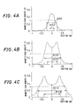
- FIGs. 4A through 4C and FIGs. 5A through 5C are graphs showing the measured results of the distribution of the magnetic field generated by the magnetic core 37.
- the distribution of magnetic flux density is measured by assuming that the capsule coating layer 12 of the magnetic display sheet 10 is positioned on a plane separated from the printing face 39a of the recording head 30 by a certain distance (50 ⁇ m) and by scanning a magnetic probe along this plane.
- the ordinate represents the flux density (unit T: tesla) and the abscissa represents position (mm) from the center of the magnetic core.
- FIG. 4A shows a case when the diameter d of the edge of the magnetic core 37 is 0.2 mm and the diameter D of the air gap hole is 0.5 mm. It shows a gaussian type distribution in which the magnetic flux density is maximized around the center of the magnetic core and drops sharply as the position is separated from the edge of the magnetic core.
- a reaction threshold of the magnetic display sheet 10 differs depending on the size and quantity of the magnetic particles within the micro-capsule 15 and the viscosity of the liquid within the micro-capsule 15.
- the reaction threshold of the magnetic display sheet 10 used here is about 0.3 T, so that the magnetic particles within the micro-capsule 15 are attracted to the surface side of the magnetic display sheet 10 and develop black color at the spot to which magnetism of more than 0.3 T of flux density can be applied.
- the magnetic particles within the micro-capsule 15 do not react at the spot to which only magnetism of less than 0.3 T of flux density can be applied and the white display is left as it is.
- a fine printed dot having a diameter of about 0.3 mm and less outline blur can be obtained when the diameter d of the edge of the magnetic core 37 is 0.2 mm and the diameter D of the air gap hole is 0.5 mm.
- FIG. 4B shows a case when the diameter d of the edge of the magnetic core 37 is 0.5 mm and the diameter D of the air gap hole is 0.8 mm. It shows a "caldera volcano" type distribution in which the magnetic flux density is dented slightly around the center of the magnetic core, is maximized around the circumference of the edge of the magnetic core and drops sharply as the position is separated therefrom.
- the reaction threshold of the magnetic display sheet 10 used here is about 0.3 T, so that the magnetic display sheet 10 develops black color at the spot to which magnetism of more than 0.3 T of flux density can be applied and the white display is left as it is at the spot to which only magnetism of less than 0.3 T of flux density can be applied.
- a fine printed dot having a diameter of about 0.8 mm and less outline blur can be obtained when the diameter d of the edge of the magnetic core 37 is 0.5 mm and the diameter D of the air gap hole is 0.8 mm.
- FIG. 4C shows a case when the diameter d of the edge of the magnetic core 37 is 0.8 mm and the diameter D of the air gap hole is 1.4 mm. It shows a distribution in which the flux density is dented largely around the center of the magnetic core, is maximized around the circumference of the edge of the magnetic core and drops sharply as the position is separated therefrom.
- the reaction threshold of the magnetic display sheet 10 used here is about 0.3 T, so that the magnetic display sheet 10 develops black color at the spot to which magnetism of more than 0.3 T of flux density can be applied and the white display is left as it is at the spot to which only magnetism of less than 0.3 T of flux density can be applied.
- a fine printed dot having a diameter of about 1.3 mm can be obtained when the diameter d of the edge of the magnetic core 37 is 0.8 mm and the diameter D of the air gap hole is 1.4 mm. It is noted that although the printing density at the center of the dot tends to decrease because the magnetic field decreases at the center of the magnetic core, it poses practically no problem in binary recording of black and white.
- FIG. 5A shows a case when the diameter d of the edge of the magnetic core 37 is 0.8 mm and the diameter D of the air gap hole is 2.0 mm. It shows a distribution in which the flux density is dented largely around the center of the magnetic core, is maximized around the circumference of the edge of the magnetic core and drops gradually as the position is separated therefrom.
- the reaction threshold of the magnetic display sheet 10 used here is about 0.3 T, so that the magnetic display sheet 10 develops black color at the spot to which magnetism of more than 0.3 T of flux density-can be applied and the white display is left as it is at the spot to which only magnetism of less than 0.3 T of flux density can be applied.
- a fine printed dot having a diameter of about 1.1 mm can be obtained when the diameter d of the edge of the magnetic core 37 is 0.8 mm and the diameter D of the air gap hole is 2.0 mm.
- the printing density at the center of the dot tends to decrease because the magnetic field decreases at the center of the magnetic core, it poses practically no problem in binary recording of black and white.
- the outline of the dot is blurred because the flux density gently passes the reaction threshold of the magnetic display sheet 10 from the inner peripheral edge of the air gap hole to the circumference of the edge of the magnetic core, such a level of blur poses practically no problem.
- FIG. 5B shows a case when the diameter d of the edge of the magnetic core 37 is 1.1 mm and the diameter D of the air gap hole is 1.4 mm. It shows a distribution in which the flux density is dented largely around the center of the magnetic core, is maximized around the circumference of the edge of the magnetic core and drops sharply as the position is separated therefrom.
- the reaction threshold of the magnetic display sheet 10 used here is about 0.3 T, so that the magnetic display sheet 10 develops black color at the spot to which magnetism of more than 0.3 T of flux density can be applied and the white display is left as it is at the spot to which only magnetism of less than 0.3 T of flux density can be applied.
- FIG. 5C shows a case when the diameter d of the edge of the magnetic core 37 is 1.1 mm and the diameter D of the air gap hole is 1.7 mm. It shows a distribution in which the flux density is dented largely around the center of the magnetic core, is maximized around the circumference of the edge of the magnetic core and drops sharply as the position is separated therefrom.
- the reaction threshold of the magnetic display sheet 10 used here is about 0.3 T, so that the magnetic display sheet 10 develops black color at the spot to which magnetism of more than 0.3 T of flux density can be applied and the white display is left as it is at the spot to which only magnetism of less than 0.3 T of flux density can be applied.
- the distribution of the magnetic field thus changes in various ways when the diameter d of the edge of the magnetic core 37 and the diameter D of the air gap hole are changed. It can be also seen that although the absolute value of the distribution itself of the magnetic fluxes shown in FIGs. 4 and 5 may change, the tendency of the distribution is not changed so much even when the quantity of current to be fed to the electromagnetic coil 38 in the recording head 39 is changed more or less. Accordingly, it is possible to optimize the shape of the printed dot by controlling the quantity of current to be fed and the feed time corresponding to the sensitivity of the magnetic display sheet 10. It can be seen from these facts that it is important to set the diameter d of the edge of the magnetic core 37 and the diameter D of the air gap hole at adequate size in advance.
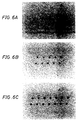
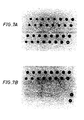
- FIGs. 6A through 6C and FIGs. 7A and 7B are enlarged photographs showing samples of prints magnetically printed on the magnetic display sheet by changing the diameter d of the edge of the magnetic core 37 and the diameter D of the air gap hole variously.
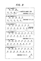
- FIG. 8 is an explanatory chart showing printing conditions corresponding to the printed dots on the photographs.
- FIG. 6A shows printed dots when the diameter D of the air gap hole is 0.5 mm and the diameter d of the edge of the magnetic core is 0.2 mm (lower row) and is 0.5 mm (upper row).
- FIG. 6B shows printed dots when the diameter D of the air gap hole is 0.8 mm and the diameter d of the edge of the magnetic core is 0.2 mm (four dots on the left), is 0.5 mm (three dots on the right in the lower row) and is 0.8 mm (three dots on the right in the upper row).
- 6C shows printed dots when the diameter D of the air gap hole is 1.1 mm and the diameter d of the edge of the magnetic core is 0.2 mm (four dots on the left), is 0.5 mm (three dots on the right in the lower row), is 0.8 mm (four dots in the middle) and is 1.1 mm (three dots on the right in the upper row).
- FIG. 7A shows printed dots in first and second rows when the diameter D of the air gap hole is 1.4 mm and the diameter d of the edge of the magnetic core is 0.2 mm (four dots on the left), is 0.5 mm (three dots in the middle on the second row), is 0.8 mm (three dots in the middle in the first row), is 1.1 mm (three dots on the right in the second row) and is 1.4 mm (three dots on the right in the first row) and printed dots in third and fourth rows when the diameter D of the air gap hole is 1.7 mm and the diameter d of the edge of the magnetic core 37 is 0.2 mm (four dots on the left in the fourth row), is 0.5 mm (three dots on the left in the third row), is 0.8 mm (three dots in the middle in the fourth row), is 1.1 mm (three dots in the middle in the third row), is 1.4 mm (two dots on the right in the third row) and is 1.7 mm (two dots on the right in the fourth row).
- FIG. 7B shows printed dots when the diameter D of the air gap hole is 2.0 mm and the diameter d of the edge of the magnetic core is 0.2 mm (three dots on the left in the lower row), is 0.5 mm (three dots on the left in the upper row), is 0.8 mm (three dots in the middle in the lower row), is 1.1 mm (three dots in the middle in the upper row), is 1.4 mm (two dots on the right in the upper row) and is 1.7 mm (two dots on the right in the lower row). Two other dots are those when the diameter d is 2.0 mm.
- the hollow printed dot is generated under the condition when the diameter d of the edge of the magnetic core is 1.1 mm or more. It can be also seen that the printed dot having a high printing density and a high contrast can be obtained when the diameter D of the air gap hole is 1.4 mm or less.
Landscapes
- Physics & Mathematics (AREA)
- General Physics & Mathematics (AREA)
- Engineering & Computer Science (AREA)
- Theoretical Computer Science (AREA)
- Electrochromic Elements, Electrophoresis, Or Variable Reflection Or Absorption Elements (AREA)
- Devices For Indicating Variable Information By Combining Individual Elements (AREA)
Description
- The present invention relates to a magnetic head for recording and displaying a still image on a magnetic display medium based on printing information sent from an external host unit.
- Hitherto, there has been known a magneto-sensitive magnetic display sheet as a display medium for developing/erasing colors in response to the direction and strength of a magnetic field (as disclosed in Japanese Unexamined Patent Publication JP-A 48-56393 (1973) and JP-A 2-146082 (1990) for example).
- Because simple letters and graphics can be drawn on such a magnetic display sheet by touching the surface of the sheet with a magnetic pen containing a magnet and it can be used over and over again by erasing them, it has been put into practical use as a simple notepad.
- Lately, an electronic information display apparatus for recording and displaying a still image on the magnetic display sheet by a recording head generating a dot matrix magnetic field based on printing information sent from an external host unit is being developed. Because the electronic information display apparatus allows contents to be displayed to be arbitrarily changed by remote control from the external host unit, a great variety of information may be given and advertised widely to pedestrians when installing it at public facilities, train stations, shops and the like. Further, because it requires no works for repapering posters and contributes in saving resources such as papers, it is considered to be promising as a future bulletin board.
- In such electronic information display apparatus, a magnetic head is used to generate the dot matrix recording magnetic field based on printing signals (as disclosed in Japanese Unexamined Patent Publication JP-A 63-259678 (1988) and JP-A 7-281621 (1995) for example). The magnetic head is composed of a plurality of magnetic cores arranged in a row or in a plurality of rows for example, a plurality of electromagnetic coils mounted to each magnetic core, a yoke provided around each magnetic core with an air gap for leaking magnetism formed therebetween and others.
- Because semi-ringed lines of magnetic force are formed between an edge of the magnetic core and the yoke in such magnetic head, the strength of the magnetic field is maximized at the position slightly separated in the radial direction from the extension of an axis of the magnetic core. Therefore, when the magnetic field generated by one magnetic core reaches the magnetic display sheet, it may create a hollow ringed printed dot whose density around the dot is higher than that at the center of the dot.
- The printed dot is preferred to be a circular dot having a diameter slightly larger than a size of a pixel corresponding to a recording density and for that end, it is ideal for the recording magnetic field to have a columnar distribution. However, it is difficult in reality because the distribution of the magnetic field largely changes depending on the dimension of the magnetic core and the air gap.
- Accordingly, it is an object of the present invention to optimise the distribution of the magnetic field generated by the magnetic core to provide a magnetic head for a magnetic display which can realise high quality magnetic printing.
- According to this invention there is provided a magnetic head as defined in
claim 1. Some of the preferred features of the magnetic head in which the invention is embodied are specified in the dependent claims. - The invention provides a magnetic head for a magnetic display comprising:
- a yoke having a printing face which faces to a magnetic display medium and an air gap hole formed in the printing face;
- a magnetic core whose edge is inserted into the air gap hole, for generating a dot-like recording magnetic field by magnetically coupling with the yoke; and
- an electromagnetic coil for supplying a magnetic field to the magnetic core based on printing signals,
- wherein a diameter d of the edge of the magnetic core is smaller than a diameter D of the air gap hole and is 0.8 mm or less.
-
- The distribution of the recording magnetic field is optimized by setting the diameter of the edge of the magnetic core to be smaller than the diameter of the air gap hole and to be 0.8 mm or less. Due to that, it becomes possible to prevent the printed dot formed on the magnetic display medium from being hollowed and the distribution of density of dot may be nearly homogenized.
- Preferably, the diameter of the air gap hole is 1.4 mm or less.
- The distribution of the recording magnetic field may be optimized and the expansion of the foot slope in the distribution may be eliminated by setting the diameter of the air gap hole to be 1.4 mm or less. Due to that, the printed dot formed on the magnetic display medium becomes clear and the fine and high density printed dot having less outline blur may be obtained.
- Preferably, the magnetic display to which the magnetic field from the magnetic head is applied is constructed so that micro-capsules containing magnetic powder and non-magnetic powder are distributed in -plain and that the size of the micro-capsule is in a range from 10 µm to 1000 µm.
- Because the clear printed dots can be obtained by the present invention, high recording density and high quality magnetic printing may be realized.
- Other and further objects, features, and advantages of the invention will be more explicit from the following detailed description taken with reference to the drawings wherein:
- FIG. 1 is a sectional view showing an electronic information display apparatus in which a magnetic head of the present invention is used;
- FIG. 2 is a partial perspective view showing an internal structure of the electronic information display apparatus shown in FIG. 1;
- FIG. 3 is a partial sectional view showing a
structure of a
magnetic display sheet 10 and themagnetic head 30; - FIGs. 4A through 4C are graphs showing the measured
results of distribution of magnetic field generated by a
magnetic core 37; - FIGs. 5A through 5C are graphs showing the measured
results of distribution of magnetic field generated by a
magnetic core 37; - FIGs. 6A through 6C are enlarged photographs showing
printed samples magnetically printed on the magnetic
display sheet by changing the diameter d of an edge of the
magnetic core 37 and the diameter D of a air gap hole variously; - FIGs. 7A through 7B are enlarged photographs showing
printed samples magnetically printed on the magnetic
display sheet by changing the diameter d of the edge of
the
magnetic core 37 and the diameter D of the air gap hole variously; and - FIG. 8 is an explanatory chart showing printing conditions which correspond to the dots printed on the photographs.
-
- Now referring to the drawings, preferred embodiments of the invention are described below.
- FIG. 1 is a sectional view showing an electronic information display apparatus in which a magnetic head in which the present invention is embodied and FIG. 2 is a partial perspective view thereof. A driven
roller 50 is disposed within the upper part of ahousing 1 and adriving roller 60 is disposed within the lower side thereof. A flexible endlessmagnetic display sheet 10 is spanned between the tworollers roller 50 is urged upward by an elastic member (not shown) such as a spring to give certain tension to themagnetic display sheet 10 to stably run the sheet and to maintain the flatness of the surface of the sheet. Theroller 60 is rotationally driven by amotor 63 viagears magnetic display sheet 10 is circulated so as to move from the bottom to the top on the front side of the housing 1 (on the left side in FIG. 1 or the back side in FIG. 2) and from the top to the bottom on the rear side of the housing 1 (the right side in FIG. 1 or the front side in FIG. 2) when theroller 60 is driven. Adisplay window 2 made of a transparent material such as acrylic resin and glass is formed on the front of thehousing 1. - A
recording head 30 is provided at the lower part of the rear moving side of themagnetic display sheet 10 and generates a dot matrix type recording magnetic field toward the surface of themagnetic display sheet 10 based on printing signals sent from an external host unit (not shown). Therecording head 30 has a plurality of electromagnetic coils disposed in stagger for example and is mounted on acarriage 31 which reciprocates in the direction of the width of the sheet. Thecarriage 31 is fixed to part of anendless belt 33 spanned between twopulleys guide shafts 32, by amotor 36 which rotationally drives thepulley 35. - An
erasing head 20 is composed of a permanent magnet and the like having a length longer than the sheet width and is disposed so as to contact closely to the back of themagnetic display sheet 10 at the upper part of the front moving side of themagnetic display sheet 10. - FIG. 3 is a partial sectional view showing a structure of the
magnetic display sheet 10 and therecording head 30. Coated and fixed around the whole surface of themagnetic display sheet 10 are micro-capsules 15 which develops colors in response to magnetism. Each micro-capsule 15 is composed of high viscous liquid and a spherical shell which encloses and holds the liquid. Dispersed within the liquid are magnetic particles which are nearly black and non-magnetic particles which are nearly white. For example, particle of black iron oxide (FeO) having a size of 0.1 to 5 µm is used as the magnetic particle and particle of white titanium oxide having a size of 0.1 to 5 pm is used as the non-magnetic particle. Further, as the high viscous liquid, organic solvent including aqueous solution, fat and oil and surface active agent type solvent is used and as the material of the shell, gelatin is mainly used. The size of the micro-capsule 15 is distributed within a range from 10 to 1000 µm. - The particle size is not preferred to be less than 10 pm because there might be a micro-capsule which is smaller than the sum of the maximum size of the magnetic particle and the maximum size of the non-magnetic particle, being unable to contain the two kinds of particles. When the particle size is more than 1000 pm on the other hand, it becomes difficult to create an adequate printed dot because the particle size becomes close to a diameter d of an edge of a
magnetic core 37 and a diameter D of a air gap hole in arecording head 39 and the number of micro-capsules 15 which represent one printed dot decreases. Further, it is not preferable that therecording head 39 as described later requires a large quantity of current because the larger the size of the micro-capsule 15, the longer the distance for moving the magnetic particles becomes. From these reasons, it can be said that the suitable size of the micro-capsule 15 is within the range from 10 to 1000 µm. - The micro-capsule 15 is mixed with
binder 14 made of highly transparent synthetic rubber type adhesive and the like and is coated to abase 11 made of a transparent material such as polyethylene terephthalate to form acapsule coating layer 12 of 40 to 1000 pm thick for example. - A
protection sheet 13 made of polypropylene long-fibre unwoven cloth and the like is adhered on the back of thecapsule coating layer 12 so as to be 30 to 1000 pm thick for example to smoothly run the sheet. - Meanwhile, the
recording head 30 comprises thebox type yoke 39 made of a material of high magnetic permeability, themagnetic core 37 made of a material of high magnetic permeability uprightly provided within theyoke 39 and anelectromagnetic coil 38 attached to themagnetic core 37. A plurality ofmagnetic cores 37 andelectromagnetic coils 38 are provided corresponding to a plurality of printed dots. While themagnetic core 37 is formed into a columnar shape, the diameter of the edge thereof is smaller than that of the middle part and a tapered portion in which the diameter changes linearly is formed therebetween. - Numbers of circular air gap holes are formed on the
printing face 39a of theyoke 39 and the edge of themagnetic core 37 is positioned at the center of each air gap hole. Leakage magnetic field is generated because there exist the air gap between themagnetic core 37 and the air gap hole. As shown in FIG. 3 as to the distribution of the magnetic field, semi-ringed lines of magnetic force are generated between the edge of themagnetic core 37 and theyoke 39 and the strength of the magnetic field is maximized at the position slightly separated in the radial direction from the extension of the axis of themagnetic core 37. Therefore, when the magnetic field generated by one of themagnetic cores 37 reaches themagnetic display sheet 10, a hollow ringed printed dot in which density thereof around the dot is higher than that at the center thereof is formed. - When the
electromagnetic coil 38 is energized selectively corresponding to printing signals, a magnetic field is generated along the axial direction of themagnetic core 37. It passes through a magnetic circuit composed of themagnetic core 37, the air gap and theyoke 39 and generates a recording magnetic field from the air gap toward themagnetic display sheet 10. - That is, the magnetic field generated by the
electromagnetic coil 38 passes through the magnetic circuit composed of the magnetic core 37 (front end), the air gap, the edge of theyoke 39, theyoke 39 and the magnetic core 37 (rear end) and generates the magnetic field having a high magnetic flux density toward the surface of the sheet around the edge of themagnetic core 37 because there exists the air gap. - Next, the principle of the magnetic recording/displaying and erasure will be explained. When the
recording head 30 approaches the surface of themagnetic display sheet 10 where thebase 11 is positioned, and generates the recording magnetic field based on printing signals, the magnetic particles dispersed within the micro-capsule 15 are attracted to the side of thebase 11 and due to the pressure, the non-magnetic particles move to the side of theprotection sheet 13. Then, the part to which the recording magnetic field has been applied is observed as if it has developed nearly black color seeing from the surface side of themagnetic display sheet 10. That is, letters and symbols may be recorded by applying magnetic fields in dot matrix by using therecording head 30. - Next, when the erasing
head 20 approaches the back of themagnetic display sheet 10, i.e. the side where theprotection sheet 13 is positioned, the magnetic particles dispersed within the micro-capsule 15 are attracted to the side of theprotection sheet 13 and due to the pressure, the non-magnetic particles move to the side of thebase 11. Then, the part to which the erasing magnetic field has been applied turns nearly white seeing from the surface side of themagnetic display sheet 10. That is, the sheet may be erased uniformly by applying the erasing magnetic field across the whole surface of the sheet width. - Liquid having a predetermined viscosity is selected for the above-mentioned high viscous liquid within the micro-capsule 15 to hold the state of display caused by the magnetic particles moved to the back or the front side when the magnetic field has been applied. That is, it is selected to prevent the state of display from being collapsed which might otherwise occur when the particles moved once to the front or the back side settle or move due to vibration and the like when the viscosity of the liquid is low. Accordingly, the magnetic attracting force of the
recording head 30 and the erasinghead 20 must exceed the yield value of the above-mentioned liquid defined by the viscosity. Writing/erasure of the display is thus implemented. - Next, an operation of the whole apparatus will be explained. Making reference to FIGs. 1 and 2, the
magnetic display sheet 10 is circulated at a constant speed to erase the whole surface with the erasinghead 20 before starting printing at first. Next, printing is carried out magnetically by receiving printing signals from the external host unit and feeding pulse current of several hundred microseconds to several tens miliseconds to theelectromagnetic coil 38 while moving therecording head 30 in the direction of the sheet width every time when the development of image data of one printing line ends and applying the dot matrix magnetic fields to the surface of themagnetic display sheet 10. - When one line of printing is finished, the
magnetic display sheet 10 is shifted by a predetermined feed pitch and is stopped to print based on image data developed for the next printing line. One sheet of image is then formed by repeating the development of the image data, the serial printing by therecording head 30 and the intermittent feed of themagnetic display sheet 10 as described above. - When a new image is to be printed, serial printing is carried out by the
recording head 30 after erasing the whole face with the erasinghead 20 by circulating themagnetic display sheet 10 at the constant speed in the same manner as described above. - Next, a result of changes of the printed dots studied by variously changing the diameter d of the edge of the
magnetic core 37 and the diameter D of the air gap hole formed in theyoke 39 will be explained. Table 1 shows whether or not a hollow is generated in the printed dot formed on themagnetic display sheet 10. In Table 1, "○" represent those printed dots having no hollow, "×" represent those printed dots having a hollow and "-" represent those which have been impossible to set, respectively.Diameter d of Edge of Magnetic Core 37 (mm) Diameter D of Air Gap Hole (mm) 0.5 0.8 1.1 1.4 1.7 2.0 0.2 ○ ○ ○ ○ ○ ○ 0.5 ○ ○ ○ ○ ○ ○ 0.8 - ○ ○ ○ ○ ○ 1.1 - - × × × × 1.4 - - - × × × 1.7 - - - - × × 2.0 - - - - - × - Table 2 shows the density of printed dots formed on the
magnetic display sheet 10. In Table 2, " o ○ " represent those printed dots having a high density, "○" represent those printed dots having a slightly low density, "×" represent those printed dots having a hollow and "-" represent those which have been impossible to set, respectively.Diameter d of Edge of Magnetic Core 37 (mm) Diameter D of Air Gap Hole (mm) 0.5 0.8 1.1 1.4 1.7 2.0 0.2 o ○ o ○ o ○ o ○ ○ ○ 0.5 o ○ o ○ o ○ o ○ ○ ○ 0.8 - o ○ o ○ o ○ ○ ○ 1.1 - - × × × × 1.4 - - - × × × 1.7 - - - - × × 2.0 - - - - - × - As seen from the above, no hollow is generated in the dot and printed dots having practically no problem may be realized when the diameter d of the edge of the
magnetic core 37 is smaller than the diameter D of the air gap hole and is in a range less than 0.8 mm. - Further, it is preferred that the diameter D of the air gap hole is less than 1.4 mm. No hollow is generated and printed dots having fully high printing density may be realized in that range.
- FIGs. 4A through 4C and FIGs. 5A through 5C are graphs showing the measured results of the distribution of the magnetic field generated by the
magnetic core 37. The distribution of magnetic flux density is measured by assuming that thecapsule coating layer 12 of themagnetic display sheet 10 is positioned on a plane separated from theprinting face 39a of therecording head 30 by a certain distance (50 µm) and by scanning a magnetic probe along this plane. The ordinate represents the flux density (unit T: tesla) and the abscissa represents position (mm) from the center of the magnetic core. - FIG. 4A shows a case when the diameter d of the edge of the
magnetic core 37 is 0.2 mm and the diameter D of the air gap hole is 0.5 mm. It shows a gaussian type distribution in which the magnetic flux density is maximized around the center of the magnetic core and drops sharply as the position is separated from the edge of the magnetic core. A reaction threshold of themagnetic display sheet 10 differs depending on the size and quantity of the magnetic particles within the micro-capsule 15 and the viscosity of the liquid within the micro-capsule 15. The reaction threshold of themagnetic display sheet 10 used here is about 0.3 T, so that the magnetic particles within the micro-capsule 15 are attracted to the surface side of themagnetic display sheet 10 and develop black color at the spot to which magnetism of more than 0.3 T of flux density can be applied. The magnetic particles within the micro-capsule 15 do not react at the spot to which only magnetism of less than 0.3 T of flux density can be applied and the white display is left as it is. Thus, a fine printed dot having a diameter of about 0.3 mm and less outline blur can be obtained when the diameter d of the edge of themagnetic core 37 is 0.2 mm and the diameter D of the air gap hole is 0.5 mm. - FIG. 4B shows a case when the diameter d of the edge of the
magnetic core 37 is 0.5 mm and the diameter D of the air gap hole is 0.8 mm. It shows a "caldera volcano" type distribution in which the magnetic flux density is dented slightly around the center of the magnetic core, is maximized around the circumference of the edge of the magnetic core and drops sharply as the position is separated therefrom. The reaction threshold of themagnetic display sheet 10 used here is about 0.3 T, so that themagnetic display sheet 10 develops black color at the spot to which magnetism of more than 0.3 T of flux density can be applied and the white display is left as it is at the spot to which only magnetism of less than 0.3 T of flux density can be applied. Thus, a fine printed dot having a diameter of about 0.8 mm and less outline blur can be obtained when the diameter d of the edge of themagnetic core 37 is 0.5 mm and the diameter D of the air gap hole is 0.8 mm. - It is noted that although the magnetic field decreases more or less at the center of the magnetic core, the same printing density with that around the circumference of the edge of the magnetic core can be obtained because it is fully larger than the reaction threshold of the
magnetic display sheet 10. - FIG. 4C shows a case when the diameter d of the edge of the
magnetic core 37 is 0.8 mm and the diameter D of the air gap hole is 1.4 mm. It shows a distribution in which the flux density is dented largely around the center of the magnetic core, is maximized around the circumference of the edge of the magnetic core and drops sharply as the position is separated therefrom. The reaction threshold of themagnetic display sheet 10 used here is about 0.3 T, so that themagnetic display sheet 10 develops black color at the spot to which magnetism of more than 0.3 T of flux density can be applied and the white display is left as it is at the spot to which only magnetism of less than 0.3 T of flux density can be applied. Thus, a fine printed dot having a diameter of about 1.3 mm can be obtained when the diameter d of the edge of themagnetic core 37 is 0.8 mm and the diameter D of the air gap hole is 1.4 mm. It is noted that although the printing density at the center of the dot tends to decrease because the magnetic field decreases at the center of the magnetic core, it poses practically no problem in binary recording of black and white. - FIG. 5A shows a case when the diameter d of the edge of the
magnetic core 37 is 0.8 mm and the diameter D of the air gap hole is 2.0 mm. It shows a distribution in which the flux density is dented largely around the center of the magnetic core, is maximized around the circumference of the edge of the magnetic core and drops gradually as the position is separated therefrom. The reaction threshold of themagnetic display sheet 10 used here is about 0.3 T, so that themagnetic display sheet 10 develops black color at the spot to which magnetism of more than 0.3 T of flux density-can be applied and the white display is left as it is at the spot to which only magnetism of less than 0.3 T of flux density can be applied. Thus, a fine printed dot having a diameter of about 1.1 mm can be obtained when the diameter d of the edge of themagnetic core 37 is 0.8 mm and the diameter D of the air gap hole is 2.0 mm. It is noted that although the printing density at the center of the dot tends to decrease because the magnetic field decreases at the center of the magnetic core, it poses practically no problem in binary recording of black and white. Further, although it shows a tendency that the outline of the dot is blurred because the flux density gently passes the reaction threshold of themagnetic display sheet 10 from the inner peripheral edge of the air gap hole to the circumference of the edge of the magnetic core, such a level of blur poses practically no problem. - FIG. 5B shows a case when the diameter d of the edge of the
magnetic core 37 is 1.1 mm and the diameter D of the air gap hole is 1.4 mm. It shows a distribution in which the flux density is dented largely around the center of the magnetic core, is maximized around the circumference of the edge of the magnetic core and drops sharply as the position is separated therefrom. The reaction threshold of themagnetic display sheet 10 used here is about 0.3 T, so that themagnetic display sheet 10 develops black color at the spot to which magnetism of more than 0.3 T of flux density can be applied and the white display is left as it is at the spot to which only magnetism of less than 0.3 T of flux density can be applied. No adequate printed dot cannot be obtained when the diameter d of the edge of themagnetic core 37 is 1.1 mm and the diameter D of the air gap hole is 1.4 mm because no color is developed around the center because the flux density around the center is less than the reaction threshold of themagnetic display sheet 10 and a ringed hollow dot having an outer diameter of about 1.4 mm and an inner diameter of about 0.4 mm is formed. - FIG. 5C shows a case when the diameter d of the edge of the
magnetic core 37 is 1.1 mm and the diameter D of the air gap hole is 1.7 mm. It shows a distribution in which the flux density is dented largely around the center of the magnetic core, is maximized around the circumference of the edge of the magnetic core and drops sharply as the position is separated therefrom. The reaction threshold of themagnetic display sheet 10 used here is about 0.3 T, so that themagnetic display sheet 10 develops black color at the spot to which magnetism of more than 0.3 T of flux density can be applied and the white display is left as it is at the spot to which only magnetism of less than 0.3 T of flux density can be applied. No adequate printed dot cannot be obtained when the diameter d of the edge of themagnetic core 37 is 1.1 mm and the diameter D of the air gap hole is 1.7 mm because no color is developed around the center because the flux density around the center is less than the reaction threshold of themagnetic display sheet 10 and a ringed hollow dot having an outer diameter of about 1.6 mm and an inner diameter of about 0.5 mm is formed. - It can be seen that the distribution of the magnetic field thus changes in various ways when the diameter d of the edge of the
magnetic core 37 and the diameter D of the air gap hole are changed. It can be also seen that although the absolute value of the distribution itself of the magnetic fluxes shown in FIGs. 4 and 5 may change, the tendency of the distribution is not changed so much even when the quantity of current to be fed to theelectromagnetic coil 38 in therecording head 39 is changed more or less. Accordingly, it is possible to optimize the shape of the printed dot by controlling the quantity of current to be fed and the feed time corresponding to the sensitivity of themagnetic display sheet 10. It can be seen from these facts that it is important to set the diameter d of the edge of themagnetic core 37 and the diameter D of the air gap hole at adequate size in advance. - Next, experiments on evaluation of print will be explained. FIGs. 6A through 6C and FIGs. 7A and 7B are enlarged photographs showing samples of prints magnetically printed on the magnetic display sheet by changing the diameter d of the edge of the
magnetic core 37 and the diameter D of the air gap hole variously. FIG. 8 is an explanatory chart showing printing conditions corresponding to the printed dots on the photographs. - FIG. 6A shows printed dots when the diameter D of the air gap hole is 0.5 mm and the diameter d of the edge of the magnetic core is 0.2 mm (lower row) and is 0.5 mm (upper row). FIG. 6B shows printed dots when the diameter D of the air gap hole is 0.8 mm and the diameter d of the edge of the magnetic core is 0.2 mm (four dots on the left), is 0.5 mm (three dots on the right in the lower row) and is 0.8 mm (three dots on the right in the upper row). FIG. 6C shows printed dots when the diameter D of the air gap hole is 1.1 mm and the diameter d of the edge of the magnetic core is 0.2 mm (four dots on the left), is 0.5 mm (three dots on the right in the lower row), is 0.8 mm (four dots in the middle) and is 1.1 mm (three dots on the right in the upper row).
- FIG. 7A shows printed dots in first and second rows when the diameter D of the air gap hole is 1.4 mm and the diameter d of the edge of the magnetic core is 0.2 mm (four dots on the left), is 0.5 mm (three dots in the middle on the second row), is 0.8 mm (three dots in the middle in the first row), is 1.1 mm (three dots on the right in the second row) and is 1.4 mm (three dots on the right in the first row) and printed dots in third and fourth rows when the diameter D of the air gap hole is 1.7 mm and the diameter d of the edge of the
magnetic core 37 is 0.2 mm (four dots on the left in the fourth row), is 0.5 mm (three dots on the left in the third row), is 0.8 mm (three dots in the middle in the fourth row), is 1.1 mm (three dots in the middle in the third row), is 1.4 mm (two dots on the right in the third row) and is 1.7 mm (two dots on the right in the fourth row). FIG. 7B shows printed dots when the diameter D of the air gap hole is 2.0 mm and the diameter d of the edge of the magnetic core is 0.2 mm (three dots on the left in the lower row), is 0.5 mm (three dots on the left in the upper row), is 0.8 mm (three dots in the middle in the lower row), is 1.1 mm (three dots in the middle in the upper row), is 1.4 mm (two dots on the right in the upper row) and is 1.7 mm (two dots on the right in the lower row). Two other dots are those when the diameter d is 2.0 mm. - It can be seen from the photographs that the hollow printed dot is generated under the condition when the diameter d of the edge of the magnetic core is 1.1 mm or more. It can be also seen that the printed dot having a high printing density and a high contrast can be obtained when the diameter D of the air gap hole is 1.4 mm or less.
- The invention may be embodied in other specific forms without departing from the spirit or essential characteristics thereof. The present embodiments are therefore to be considered in all respects as illustrative and not restrictive, the scope of the invention being indicated by the appended claims rather than by the foregoing description and all changes which come within the meaning and the range of equivalency of the claims are therefore intended to be embraced therein.
Claims (3)
- A magnetic head for a magnetic display comprising:a yoke (39) having a printing face (39a) which faces to a magnetic display medium (10) and an air gap hole formed in the printing face;a magnetic core (37) whose edge is inserted into the air gap hole, for generating a dot-like recording magnetic field by magnetically coupling with the yoke; andan electromagnetic coil (38) for supplying a magnetic field to the magnetic core based on printing signals,wherein a diameter d of the edge of the magnetic core is smaller than a diameter D of the air gap hole and characterised in that the diameter d is 0.8 mm or less.
- A magnetic head according to claim 1, characterised in that the diameter D of the air gap hole is 1.4mm or less.
- A magnetic head according to claim 1 or claim 2, characterised in that the magnetic display medium (10) to which the magnetic field from the magnetic head is applied comprises micro-capsules (15) containing magnetic powder and non-magnetic powder, the size of the micro-capsules being in a range from 10 micrometers to 1,000 micrometers.
Applications Claiming Priority (3)
| Application Number | Priority Date | Filing Date | Title |
|---|---|---|---|
| JP297995/96 | 1996-10-21 | ||
| JP8297995A JPH10123987A (en) | 1996-10-21 | 1996-10-21 | Magnetic head for magnetic display |
| JP29799596 | 1996-10-21 |
Publications (2)
| Publication Number | Publication Date |
|---|---|
| EP0837440A1 EP0837440A1 (en) | 1998-04-22 |
| EP0837440B1 true EP0837440B1 (en) | 2000-03-15 |
Family
ID=17853776
Family Applications (1)
| Application Number | Title | Priority Date | Filing Date |
|---|---|---|---|
| EP19970308356 Expired - Lifetime EP0837440B1 (en) | 1996-10-21 | 1997-10-21 | A magnetic head for a magnetic display |
Country Status (3)
| Country | Link |
|---|---|
| EP (1) | EP0837440B1 (en) |
| JP (1) | JPH10123987A (en) |
| DE (1) | DE69701435T2 (en) |
Families Citing this family (2)
| Publication number | Priority date | Publication date | Assignee | Title |
|---|---|---|---|---|
| US7158111B1 (en) * | 2000-03-30 | 2007-01-02 | Intel Corporation | Flexible display |
| US8077142B2 (en) * | 2006-09-27 | 2011-12-13 | Tred Displays Corporation | Reflective, bi-stable magneto optical display architectures |
Family Cites Families (5)
| Publication number | Priority date | Publication date | Assignee | Title |
|---|---|---|---|---|
| JPS63259678A (en) * | 1987-04-17 | 1988-10-26 | 株式会社パイロット | Writing electromagnet for magnetic panel |
| DE3774375D1 (en) * | 1986-08-29 | 1991-12-12 | Pilot Pen Co Ltd | MAGNETIC DISPLAY DEVICE. |
| JP2873825B2 (en) * | 1988-11-28 | 1999-03-24 | 株式会社 日本カプセルプロダクツ | Magnetic display system |
| JP2850056B2 (en) * | 1990-12-28 | 1999-01-27 | 株式会社 日本カプセルプロダクツ | Magnetic display system |
| JP3091632B2 (en) * | 1994-04-13 | 2000-09-25 | スター精密株式会社 | Magnetophoretic display head |
-
1996
- 1996-10-21 JP JP8297995A patent/JPH10123987A/en active Pending
-
1997
- 1997-10-21 EP EP19970308356 patent/EP0837440B1/en not_active Expired - Lifetime
- 1997-10-21 DE DE1997601435 patent/DE69701435T2/en not_active Expired - Fee Related
Also Published As
| Publication number | Publication date |
|---|---|
| DE69701435T2 (en) | 2000-07-20 |
| JPH10123987A (en) | 1998-05-15 |
| EP0837440A1 (en) | 1998-04-22 |
| HK1006647A1 (en) | 1999-03-12 |
| DE69701435D1 (en) | 2000-04-20 |
Similar Documents
| Publication | Publication Date | Title |
|---|---|---|
| KR970005352B1 (en) | Visual magnetic recording medium & method of making the same | |
| JP2003071978A (en) | Magnetic adsorption sheet | |
| EP0837440A1 (en) | A magnetic head for a magnetic display | |
| HK1006647B (en) | A magnetic head for a magnetic display | |
| EP0848366A2 (en) | Magnetic head for magnetic display and magnetic display | |
| EP0258791A2 (en) | Magnetic display unit | |
| JPH1055139A (en) | Electronic information display | |
| HK1009020A (en) | Magnetic head for magnetic display and magnetic display | |
| JPH1039802A (en) | Electronic information display | |
| JPH1055140A (en) | Electronic information display | |
| JPH1031436A (en) | Electronic information display | |
| JPH09218657A (en) | Electronic information display | |
| JPH10232630A (en) | Color display sheet and electronic information display device | |
| JPH1031437A (en) | Electronic information display device | |
| JPH10214051A (en) | Electronic information display | |
| EP0831448A2 (en) | Electronic information display apparatus | |
| JPH09230807A (en) | Method of manufacturing magnetic head for magnetic display | |
| JPH10198294A (en) | Electronic information display | |
| JPH09218656A (en) | Electronic information display | |
| JPH10222106A (en) | Electronic information display | |
| JP3209498B2 (en) | Magnetic head for magnetic display | |
| JPH09297545A (en) | Magnetic head for magnetic display | |
| JPH09218655A (en) | Electronic information display | |
| JPH1091104A (en) | Electronic information display | |
| CA1199362A (en) | Magnetic dot matrix printing |
Legal Events
| Date | Code | Title | Description |
|---|---|---|---|
| PUAI | Public reference made under article 153(3) epc to a published international application that has entered the european phase |
Free format text: ORIGINAL CODE: 0009012 |
|
| AK | Designated contracting states |
Kind code of ref document: A1 Designated state(s): DE FR GB IT |
|
| AX | Request for extension of the european patent |
Free format text: AL;LT;LV;RO;SI |
|
| 17P | Request for examination filed |
Effective date: 19980525 |
|
| AKX | Designation fees paid |
Free format text: DE FR GB IT |
|
| RBV | Designated contracting states (corrected) |
Designated state(s): DE FR GB IT |
|
| GRAG | Despatch of communication of intention to grant |
Free format text: ORIGINAL CODE: EPIDOS AGRA |
|
| 17Q | First examination report despatched |
Effective date: 19990624 |
|
| GRAG | Despatch of communication of intention to grant |
Free format text: ORIGINAL CODE: EPIDOS AGRA |
|
| GRAH | Despatch of communication of intention to grant a patent |
Free format text: ORIGINAL CODE: EPIDOS IGRA |
|
| GRAH | Despatch of communication of intention to grant a patent |
Free format text: ORIGINAL CODE: EPIDOS IGRA |
|
| GRAA | (expected) grant |
Free format text: ORIGINAL CODE: 0009210 |
|
| AK | Designated contracting states |
Kind code of ref document: B1 Designated state(s): DE FR GB IT |
|
| PG25 | Lapsed in a contracting state [announced via postgrant information from national office to epo] |
Ref country code: IT Free format text: LAPSE BECAUSE OF FAILURE TO SUBMIT A TRANSLATION OF THE DESCRIPTION OR TO PAY THE FEE WITHIN THE PRE;WARNING: LAPSES OF ITALIAN PATENTS WITH EFFECTIVE DATE BEFORE 2007 MAY HAVE OCCURRED AT ANY TIME BEFORE 2007. THE CORRECT EFFECTIVE DATE MAY BE DIFFERENT FROM THE ONE RECORDED.SCRIBED TIME-LIMIT Effective date: 20000315 |
|
| REF | Corresponds to: |
Ref document number: 69701435 Country of ref document: DE Date of ref document: 20000420 |
|
| ET | Fr: translation filed | ||
| PLBE | No opposition filed within time limit |
Free format text: ORIGINAL CODE: 0009261 |
|
| STAA | Information on the status of an ep patent application or granted ep patent |
Free format text: STATUS: NO OPPOSITION FILED WITHIN TIME LIMIT |
|
| 26N | No opposition filed | ||
| PGFP | Annual fee paid to national office [announced via postgrant information from national office to epo] |
Ref country code: FR Payment date: 20011010 Year of fee payment: 5 |
|
| PGFP | Annual fee paid to national office [announced via postgrant information from national office to epo] |
Ref country code: GB Payment date: 20011024 Year of fee payment: 5 |
|
| PGFP | Annual fee paid to national office [announced via postgrant information from national office to epo] |
Ref country code: DE Payment date: 20011105 Year of fee payment: 5 |
|
| REG | Reference to a national code |
Ref country code: GB Ref legal event code: IF02 |
|
| PG25 | Lapsed in a contracting state [announced via postgrant information from national office to epo] |
Ref country code: GB Free format text: LAPSE BECAUSE OF NON-PAYMENT OF DUE FEES Effective date: 20021021 |
|
| PG25 | Lapsed in a contracting state [announced via postgrant information from national office to epo] |
Ref country code: DE Free format text: LAPSE BECAUSE OF NON-PAYMENT OF DUE FEES Effective date: 20030501 |
|
| GBPC | Gb: european patent ceased through non-payment of renewal fee |
Effective date: 20021021 |
|
| PG25 | Lapsed in a contracting state [announced via postgrant information from national office to epo] |
Ref country code: FR Free format text: LAPSE BECAUSE OF NON-PAYMENT OF DUE FEES Effective date: 20030630 |
|
| REG | Reference to a national code |
Ref country code: FR Ref legal event code: ST |