EP0837215B1 - Rock bit cutter retainer - Google Patents
Rock bit cutter retainer Download PDFInfo
- Publication number
- EP0837215B1 EP0837215B1 EP97308197A EP97308197A EP0837215B1 EP 0837215 B1 EP0837215 B1 EP 0837215B1 EP 97308197 A EP97308197 A EP 97308197A EP 97308197 A EP97308197 A EP 97308197A EP 0837215 B1 EP0837215 B1 EP 0837215B1
- Authority
- EP
- European Patent Office
- Prior art keywords
- threads
- bearing
- threaded ring
- cutter
- rolling cutter
- Prior art date
- Legal status (The legal status is an assumption and is not a legal conclusion. Google has not performed a legal analysis and makes no representation as to the accuracy of the status listed.)
- Expired - Lifetime
Links
- 239000011435 rock Substances 0.000 title description 2
- 238000005096 rolling process Methods 0.000 claims description 39
- 239000011295 pitch Substances 0.000 description 23
- 230000014759 maintenance of location Effects 0.000 description 13
- 238000005553 drilling Methods 0.000 description 7
- 230000013011 mating Effects 0.000 description 7
- 230000007246 mechanism Effects 0.000 description 5
- 238000006073 displacement reaction Methods 0.000 description 4
- 230000002829 reductive effect Effects 0.000 description 4
- 230000009471 action Effects 0.000 description 3
- 230000015556 catabolic process Effects 0.000 description 3
- 238000006731 degradation reaction Methods 0.000 description 3
- 230000005489 elastic deformation Effects 0.000 description 2
- 239000000314 lubricant Substances 0.000 description 2
- 239000000463 material Substances 0.000 description 2
- 229910000831 Steel Inorganic materials 0.000 description 1
- 230000002411 adverse Effects 0.000 description 1
- 239000000956 alloy Substances 0.000 description 1
- 229910045601 alloy Inorganic materials 0.000 description 1
- 230000004075 alteration Effects 0.000 description 1
- 238000005452 bending Methods 0.000 description 1
- 230000009286 beneficial effect Effects 0.000 description 1
- 230000008859 change Effects 0.000 description 1
- 230000001627 detrimental effect Effects 0.000 description 1
- 230000000694 effects Effects 0.000 description 1
- 230000006872 improvement Effects 0.000 description 1
- 230000002452 interceptive effect Effects 0.000 description 1
- 238000005461 lubrication Methods 0.000 description 1
- 238000000034 method Methods 0.000 description 1
- 230000002093 peripheral effect Effects 0.000 description 1
- 230000002028 premature Effects 0.000 description 1
- 230000000717 retained effect Effects 0.000 description 1
- 230000002441 reversible effect Effects 0.000 description 1
- 239000010959 steel Substances 0.000 description 1
Images


Classifications
-
- E—FIXED CONSTRUCTIONS
- E21—EARTH OR ROCK DRILLING; MINING
- E21B—EARTH OR ROCK DRILLING; OBTAINING OIL, GAS, WATER, SOLUBLE OR MELTABLE MATERIALS OR A SLURRY OF MINERALS FROM WELLS
- E21B10/00—Drill bits
- E21B10/08—Roller bits
-
- E—FIXED CONSTRUCTIONS
- E21—EARTH OR ROCK DRILLING; MINING
- E21B—EARTH OR ROCK DRILLING; OBTAINING OIL, GAS, WATER, SOLUBLE OR MELTABLE MATERIALS OR A SLURRY OF MINERALS FROM WELLS
- E21B10/00—Drill bits
- E21B10/08—Roller bits
- E21B10/20—Roller bits characterised by detachable or adjustable parts, e.g. legs or axles
Definitions
- This invention relates to an improved mechanism for assembling cutters on supporting bearing spindles in roller cutter earth boring bits.
- the invention causes the retention bearing mechanism to remain centred within the bearing system of a cutter in an earth boring bit cutter during operation, thereby providing greater reliability and reduced wellbore drilling costs.
- Cutter retention systems for rolling cutter drill bits are well known in the art.
- ball bearings can be inserted through a hole in the body to fill a groove between the rolling cutter and the bit body as shown in U.S. Patent No. 3,989,315.
- a snap ring can be positioned in the same general area as the ball bearings as shown in U.S. Patent No. 4,236,764.
- a split threaded thrust bearing member can be installed in the bit as shown in U.S. Patent No. 3,971,600.
- Other threaded ring rolling cutter retention mechanisms are shown in U.S. Pat. Nos. 4,911,255; 4,991,671; 5,012,701; 5,024,539 and 5,383,525. US 5383525 discloses the features set out in the pre-characterising part of Claim 1.
- the threaded ring bearing retention mechanism has been found to provide superior cutter retention performance as compared to the other retention systems as long as the threaded ring remains securely seated within the rolling cutter. If the threaded ring becomes loosened from its intended position, the resulting excessive axial cutter displacement is detrimental to the cutter seal, resulting in premature bearing failure and shorter than expected bit life. As described in U.S. Patent No. 5,383,525, the threaded ring is designed to resist unseating after the bit is assembled by provision of mechanical alterations to the intermeshing threads so that even with the occasional reverse rotation of the rolling cutter the threaded ring will not loosen.
- the fastener's diameter is generally several times greater than its length.
- the rolling cutter is normally made with alloy steels hardened to about 40 Rockwell 'C' with yield strengths greater than 103 MPa (150,000 PSI).
- the design geometry of the cutters maximizes stiffness in the bearing area and minimizes plastic and elastic deformations. For these reasons, there is no known practical method to apply enough torque to this type of threaded assembly to ensure enough elastic strain to effectively maintain flank contact of the engaged threads in operation. Therefore, in order to ensure that the rings do not loosen in operation, portions of the threads are deformed with a special tool during assembly to eliminate back off. In extremely dynamic drilling conditions, however, the impact forces and vibrations can become so high that a small amount of back off can occur.
- a second problem associated with the loosening of the threaded ring is due to the split nature of the rings. Because each ring half can move independently, even slight backing off of the threaded ring allows each half to slide radially until the roots and crests of the mating threads engage. This can cause the effective inside diameter of the paired ring halves to change by 0.76mm (.030 inches) or more and can drastically reduce the threaded ring's retention force or cause an unacceptable gap in a radial bearing member.
- the present invention is a threaded ring bearing member for rolling cutter drill bits with at least a portion of its threads having a different pitch than its mating threads.
- thread pitch is defined as the number of threads per unit of length.
- the pitch difference is designed so that the threaded ring can be seated or otherwise located precisely with respect to the other bearing elements within the drill bit to effectively control the axial displacement of the rolling cutter on the bearing spindle within a given tolerance range.
- the difference in thread pitch causes the opposite, opposing mating flanks to engage, effectively applying a tensile or compressive force to a portion of the threaded ring bearing member, which gradually increases as the assembly is tightened.
- a rolling cutter drill bit comprising: a bit body, at least one bearing spindle on said bit body, a rolling cutter rotatably mounted on said bearing spindle, a first set of screw threads formed in one of said cutter or said bearing spindle, a portion of said first set of screw threads having a first thread pitch, a bearing mounted between said cutter and said bearing spindle, said bearing comprising a split threaded ring having a second set of screw threads, a portion of said second set of screw threads having a second thread pitch, said split threaded ring being in screw threaded engagement with one of said cutter or said bearing spindle, characterised in that said first thread pitch is different from said second thread pitch.
- a portion of one of the screw-threads may be mechanically deformed by an implement after assembly to further improve resistance to back off of the threaded retention member.
- a rolling cutter earth boring bit 10 includes a body 12 with three similar leg portions 14.
- a cantilevered bearing spindle 16 formed on each leg 14 extends inwardly and downwardly.
- a rolling cutter 18 is rotatably mounted upon each leg 14. Attached to the rolling cutter 18 are cutting inserts 20 which engage the earth to effect a drilling action and cause rotation of the rolling cutter 18.
- each cutting insert 20 will be formed of hard, wear resistant material.
- Internal passageways 22, 24 & 26, as well as a reservoir 28 and bearing area 30 of the leg 14, are filled with lubricant (not shown) during bit assembly. The lubricant helps reduce friction during bit operation and is retained within the cutter 18 by a dynamic seal 32.
- a pressure balancing diaphragm 34 serves to equalize internal and external pressures.
- One passageway 26 provides an access used in assembly of the bit.
- the cutter 18 is mounted upon the cantilevered bearing spindle 16 formed on the leg 14.
- a floating friction bearing member 36 is located between the spindle 16 and a mating bearing cavity 38 formed in the cutter 18.
- An internal thread 40 is formed on the surface of an internal cavity of the cutter adjacent the bearing area 30, and a split externally threaded retaining ring 42 is positioned in a peripheral groove 44 on the spindle 16 and is threadedly engaged with the threads 40 on the cutter 18.
- This threaded ring 42 is mounted coaxially with the cutter 18 and spindle 16, and retains the cutter 18 upon the spindle 16 by forming an interference with a flange 46 on the bearing spindle 16.
- the dimensional characteristics of the threaded ring 42, the groove 44 in the spindle 16, and the cavity 38 in the cutter are such as to allow some axial displacement of the cutter 18 with respect to the spindle 16.
- the threaded ring bearing 42 is formed of two similar halves 43, and is configured with a threaded surface on its outside diameter when the two halves are joined at assembly.
- a threaded ring bearing 142 is shown in various forms of engagement with the cutter 118.
- the ring 142 is shown made up tight with the cutter 118.
- the threads 148 on the threaded ring 142 engage the threads 140 in the cutter 118 along the flanks 156 leaving relative large gaps 150 between the sets of threads due to normal machine thread practice.
- threads 48 of the threaded ring bearing 42 are formed with a slightly different pitch than the threads 40 in the cutter 18.
- thread pitch is defined as the number of threads per unit of length.
- the thread pitch of the threaded ring bearing 42 is slightly greater than the thread pitch of the cutter threads 40.
- the difference in pitch depends upon the engaged length of the threads, the thread form, and the amount of assembly torque desired. In most rolling cutter drill bits the difference in the thread pitch of the threaded bearing member 42 is between 05% and 5% of the thread pitch of the cutter threads 40.
- the configuration of the threaded bearing 42 of Figure 6 is such that the engaged flanks 56 at opposite ends of the ring provide interference in the threads as the assembly is subjected to assembly torque.
- the interference force acts on the flanks 56 in a manner that tends to push the threaded ring bearing 42 away from the cutter 18. This force, therefore pushes each half of the split pair of threaded rings together. Given sufficient assembly interference, even 10 or more degrees of back-off of this assembly will not allow these threaded ring bearings 42 to move radially by any appreciable amount.
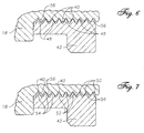
- FIG. 7 Another embodiment of the present invention is shown in Figure 7.
- the threaded ring bearing 42 has thread sets 50, 52 and 54 spaced such that there are effectively three different thread pitches.
- the operating principle is the same.
- the flanks 56 at the opposite ends of the engaged threads act to provide interference in the same manner described above.
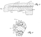
- FIG 8. Still another embodiment of the present invention is shown in Figure 8.
- the threaded ring bearing 42 has a small set of threads 66 which has a different thread pitch than the remaining threads 68. In this configuration all the interference is contained within the engaged flanks 56 of the small set of threads 66.
- the operating principle is the same. When the two members are assembled, an assembly torque is reached which will remain essentially constant over a variable engagement distance. With this design it is possible to have the benefits of differentially pitch threads in a single threaded ring bearing design even though the total amount of thread engagement for different implementations may vary.
- FIG. 9 A configuration for a threaded ring bearing 60 which provides both thrust and radial bearing functions is shown in Figure 9.
- the threads 62 of the threaded ring bearing 60 engage the cutter threads 40 over a longer engaged length.
- the difference in thread pitch for this bearing 60 would typically be much less than the pitch difference for the threaded ring bearings 42 shown in Figures 6, 7 and 8.
- threaded rings are shown as having two segments, the rings may be constructed with more than two segments.
- threads shown in the figures are typical straight machine screw threads, many other thread forms may be used, such as Acme type threads or tapered threads, without departing from the scope of the present invention.
Landscapes
- Engineering & Computer Science (AREA)
- Life Sciences & Earth Sciences (AREA)
- Geology (AREA)
- Mining & Mineral Resources (AREA)
- Mechanical Engineering (AREA)
- Physics & Mathematics (AREA)
- Environmental & Geological Engineering (AREA)
- Fluid Mechanics (AREA)
- General Life Sciences & Earth Sciences (AREA)
- Geochemistry & Mineralogy (AREA)
- Earth Drilling (AREA)
Description
- This invention relates to an improved mechanism for assembling cutters on supporting bearing spindles in roller cutter earth boring bits. The invention causes the retention bearing mechanism to remain centred within the bearing system of a cutter in an earth boring bit cutter during operation, thereby providing greater reliability and reduced wellbore drilling costs.
- Cutter retention systems for rolling cutter drill bits are well known in the art. For example, ball bearings can be inserted through a hole in the body to fill a groove between the rolling cutter and the bit body as shown in U.S. Patent No. 3,989,315. Alternatively, a snap ring can be positioned in the same general area as the ball bearings as shown in U.S. Patent No. 4,236,764. Finally, a split threaded thrust bearing member can be installed in the bit as shown in U.S. Patent No. 3,971,600. Other threaded ring rolling cutter retention mechanisms are shown in U.S. Pat. Nos. 4,911,255; 4,991,671; 5,012,701; 5,024,539 and 5,383,525. US 5383525 discloses the features set out in the pre-characterising part of Claim 1.
- The threaded ring bearing retention mechanism has been found to provide superior cutter retention performance as compared to the other retention systems as long as the threaded ring remains securely seated within the rolling cutter. If the threaded ring becomes loosened from its intended position, the resulting excessive axial cutter displacement is detrimental to the cutter seal, resulting in premature bearing failure and shorter than expected bit life. As described in U.S. Patent No. 5,383,525, the threaded ring is designed to resist unseating after the bit is assembled by provision of mechanical alterations to the intermeshing threads so that even with the occasional reverse rotation of the rolling cutter the threaded ring will not loosen. In spite of this improvement, there is evidence that bits runs under extremely adverse conditions would have performed even better at times, were it not for degradation of the threaded ring bearing retention mechanism. In exploring the reasons for this degradation, the first problem found was that the beneficial effect of deforming the threads at assembly could be significantly reduced by relative radial movement between the engaged threads of the ring and the cutter during operation. This movement is possible because the normal tolerances in threads allow significant clearances between the crests, flanks, and roots of mating threads. In common screw thread fastening systems, this clearance is not at issue because the assembly torque causes enough elastic energy to be stored in the fastener to cause the mating thread flanks to remain engaged. This is possible because the diameter of the threaded fastener is generally much less than its length, allowing high linear strain in the fastener with relatively low assembly torque.
- In drill bits with threaded ring bearing retention systems, however, the fastener's diameter is generally several times greater than its length. The rolling cutter is normally made with alloy steels hardened to about 40 Rockwell 'C' with yield strengths greater than 103 MPa (150,000 PSI). The design geometry of the cutters maximizes stiffness in the bearing area and minimizes plastic and elastic deformations. For these reasons, there is no known practical method to apply enough torque to this type of threaded assembly to ensure enough elastic strain to effectively maintain flank contact of the engaged threads in operation. Therefore, in order to ensure that the rings do not loosen in operation, portions of the threads are deformed with a special tool during assembly to eliminate back off. In extremely dynamic drilling conditions, however, the impact forces and vibrations can become so high that a small amount of back off can occur.
- Once any type of threaded fastener loosens, even slightly, it can wobble about. In rolling cutter drill bits using threaded bearing rings, this wobbling about can effectively nullify any deformation of threads performed to secure the assembly by nibbling away the deformed material or by bending it back to its original position.
- A second problem associated with the loosening of the threaded ring is due to the split nature of the rings. Because each ring half can move independently, even slight backing off of the threaded ring allows each half to slide radially until the roots and crests of the mating threads engage. This can cause the effective inside diameter of the paired ring halves to change by 0.76mm (.030 inches) or more and can drastically reduce the threaded ring's retention force or cause an unacceptable gap in a radial bearing member.
- Similar problems can occur in rock bit bearing systems designed primarily to carry the radial loads imposed by the cutter on the bearing spindle. This type ofbearing often doubles as both a thrust retention bearing and a radial load carrying bearing. Two such bearing designs are shown in U.S. Patent Nos. 4,865,137 and 5,024,539.
- In extreme drilling conditions, impact and vibration forces present during drilling can cause slight loosening of prior art threaded rings. This is most evident when drilling wellbores with high angular deviations. In these circumstances it has been found that the normal thread clearances in these threaded rings provide space for the relative radial sliding or wobbling between the engaged threads. This radial movement can remove the mechanical deformation used to prevent loosening of the threads. The radial movement also enlarges the effective diameter of the retention member, causing loss of engaging interference between the threaded ring and the flange on the bearing spindle. Both of these problems can limit the performance of a rolling cutter drill bit.
- For these reasons, there is a need for a drill bit with a threaded ring cutter bearing system which will not allow significant radial movement between the engaged threads even if some back-off of the threads occurs.
- The present invention is a threaded ring bearing member for rolling cutter drill bits with at least a portion of its threads having a different pitch than its mating threads. In this specification, thread pitch is defined as the number of threads per unit of length. The pitch difference is designed so that the threaded ring can be seated or otherwise located precisely with respect to the other bearing elements within the drill bit to effectively control the axial displacement of the rolling cutter on the bearing spindle within a given tolerance range. Upon assembly, the difference in thread pitch causes the opposite, opposing mating flanks to engage, effectively applying a tensile or compressive force to a portion of the threaded ring bearing member, which gradually increases as the assembly is tightened.
- The action of the ramp angles on the opposing thread flanks between the threaded ring and its mating threads in the cutter bore forces the two ring halves together in the centre of the bore as the assembly is tightened. This eliminates any possible radial movement between the engaged threads. Because elastic deformations are involved, no radial movement will occur with a small amount of loosening of the assembly. This action effectively prevents two modes of threaded ring degradation found in drill bits run in extreme drilling environments.
- According to one aspect of the invention there is provided a rolling cutter drill bit comprising: a bit body, at least one bearing spindle on said bit body, a rolling cutter rotatably mounted on said bearing spindle, a first set of screw threads formed in one of said cutter or said bearing spindle, a portion of said first set of screw threads having a first thread pitch, a bearing mounted between said cutter and said bearing spindle, said bearing comprising a split threaded ring having a second set of screw threads, a portion of said second set of screw threads having a second thread pitch, said split threaded ring being in screw threaded engagement with one of said cutter or said bearing spindle, characterised in that said first thread pitch is different from said second thread pitch.
- A portion of one of the screw-threads may be mechanically deformed by an implement after assembly to further improve resistance to back off of the threaded retention member.
-
- Figure 1 is a perspective view of a rolling cutter drill bit of the present invention.
- Figure 2 is a cross sectional view of one preferred embodiment of an earth boring bit of the present invention showing the general arrangement of the cutter's lubrication and bearing system.
- Figure 2a is a perspective view of a threaded ring bearing of one embodiment of the present invention.
- Figure 3 is an enlarged cross sectional view of the threads of the prior art threaded ring engaged in the threads of the rolling cutter.
- Figure 4 is an enlarged cross sectional view of the threads of the prior art threaded ring engaged in the threads of the rolling cutter with the ring slightly loosened.
- Figure 5 is an enlarged cross sectional view of the threads of the prior art threaded ring engaged in the threads of the rolling cutter with the ring slightly loosened showing a radial displacement caused by the further meshing of the loosened threads.
- Figure 6 is an enlarged cross sectional view of the threads of the present invention.
- Figure 7 is an enlarged cross sectional view of the threads of an alternative embodiment of the present invention.
- Figure 8 is an enlarged cross sectional view of the threads of another embodiment of the present invention.
- Figure 9 is an cross sectional view of the threads of the present invention used as a combination thrust and radial bearing.
- Referring now to the drawings in more detail, and particularly to Figures 1 and 2, a rolling cutter earth
boring bit 10 includes abody 12 with threesimilar leg portions 14. A cantileveredbearing spindle 16 formed on eachleg 14 extends inwardly and downwardly. Arolling cutter 18 is rotatably mounted upon eachleg 14. Attached to the rollingcutter 18 are cuttinginserts 20 which engage the earth to effect a drilling action and cause rotation of the rollingcutter 18. Typically, each cuttinginsert 20 will be formed of hard, wear resistant material.Internal passageways reservoir 28 andbearing area 30 of theleg 14, are filled with lubricant (not shown) during bit assembly. The lubricant helps reduce friction during bit operation and is retained within thecutter 18 by adynamic seal 32. Apressure balancing diaphragm 34 serves to equalize internal and external pressures. - One
passageway 26 provides an access used in assembly of the bit. Thecutter 18 is mounted upon the cantilevered bearingspindle 16 formed on theleg 14. A floatingfriction bearing member 36 is located between thespindle 16 and amating bearing cavity 38 formed in thecutter 18. - An
internal thread 40 is formed on the surface of an internal cavity of the cutter adjacent the bearingarea 30, and a split externally threaded retainingring 42 is positioned in aperipheral groove 44 on thespindle 16 and is threadedly engaged with thethreads 40 on thecutter 18. This threadedring 42 is mounted coaxially with thecutter 18 andspindle 16, and retains thecutter 18 upon thespindle 16 by forming an interference with aflange 46 on the bearingspindle 16. - The dimensional characteristics of the threaded
ring 42, thegroove 44 in thespindle 16, and thecavity 38 in the cutter are such as to allow some axial displacement of thecutter 18 with respect to thespindle 16. - In one embodiment of the present invention shown in Figure 2A, the threaded ring bearing 42 is formed of two
similar halves 43, and is configured with a threaded surface on its outside diameter when the two halves are joined at assembly. - Referring now to the prior art threaded rings shown in Figures 3, 4, and 5, a threaded ring bearing 142 is shown in various forms of engagement with the
cutter 118. In Figure 3 thering 142 is shown made up tight with thecutter 118. Thethreads 148 on the threadedring 142 engage thethreads 140 in thecutter 118 along theflanks 156 leaving relativelarge gaps 150 between the sets of threads due to normal machine thread practice. - In Figure 4 the prior art threaded
ring 142 has very slightly unscrewed to open thegap 150 completely around each thread. This gap can occur in typical screwed fasteners with rotations of less than 10 degrees, and in the thread forms used in drill bits this rotation can be less than 5 degrees. - In Figure 5 the threaded
ring 142 has been pushed radially toward thethreads 140 in thecutter 118 to substantially close thegap 150 shown in Figure 4. Thedotted lines 152 show the position of the ring before thegap 150 is closed. Whengap 150 is closed, the inner portion of the ring moves by a distance d radially away from the center of the bearing spindle. Because this portion of the threadedring 142 engages the flange on the bearing spindle in an interfering manner to retain thecutter 118 on the bearing spindle, the retention interference available is reduced by the radial distance d. Since these threadedbearings 142 are split rings, each ring half can move independently. Therefore, the diametrical interference between the threadedring 142 and the flange can be reduced by two times d. - The preferred embodiments of the present invention are shown in Figures 6, 7, 8, and 9. In Figure 6 the
threads 48 of the threaded ring bearing 42 are formed with a slightly different pitch than thethreads 40 in thecutter 18. In this specification, thread pitch is defined as the number of threads per unit of length. In the example shown, the thread pitch of the threaded ring bearing 42 is slightly greater than the thread pitch of thecutter threads 40. The difference in pitch depends upon the engaged length of the threads, the thread form, and the amount of assembly torque desired. In most rolling cutter drill bits the difference in the thread pitch of the threaded bearingmember 42 is between 05% and 5% of the thread pitch of thecutter threads 40. For 120mm (4-3/4 inch) diameter drill bits, the range of effective thread pitch differences has been found to be from about 0.02 to 0.05 threads per mm (.5 to 1.2 threads per inch). In other bit sizes, due to the differences in the engaged length of threads, effective thread pitch differences have been found to range from about 0.004 to .08 threads per mm (.1 to about 2 threads per inch). Note however, that because there are a great number of different thread forms, engaged lengths and assembly torque's possible in threaded bearing members for drill bits, there is no set pitch differential that can be deemed as best. - The configuration of the threaded
bearing 42 of Figure 6 is such that the engaged flanks 56 at opposite ends of the ring provide interference in the threads as the assembly is subjected to assembly torque. The interference force acts on theflanks 56 in a manner that tends to push the threaded ring bearing 42 away from thecutter 18. This force, therefore pushes each half of the split pair of threaded rings together. Given sufficient assembly interference, even 10 or more degrees of back-off of this assembly will not allow these threadedring bearings 42 to move radially by any appreciable amount. - Another embodiment of the present invention is shown in Figure 7. In this embodiment, the threaded ring bearing 42 has thread sets 50, 52 and 54 spaced such that there are effectively three different thread pitches. Although formed somewhat differently than the ring of Figure 6, the operating principle is the same. The
flanks 56 at the opposite ends of the engaged threads act to provide interference in the same manner described above. - Still another embodiment of the present invention is shown in Figure 8. In this embodiment, the threaded ring bearing 42 has a small set of
threads 66 which has a different thread pitch than the remainingthreads 68. In this configuration all the interference is contained within the engaged flanks 56 of the small set ofthreads 66. Although formed somewhat differently than the rings of Figures 6 and 7, the operating principle is the same. When the two members are assembled, an assembly torque is reached which will remain essentially constant over a variable engagement distance. With this design it is possible to have the benefits of differentially pitch threads in a single threaded ring bearing design even though the total amount of thread engagement for different implementations may vary. - A configuration for a threaded ring bearing 60 which provides both thrust and radial bearing functions is shown in Figure 9. In this case the
threads 62 of the threaded ring bearing 60 engage thecutter threads 40 over a longer engaged length. The difference in thread pitch for thisbearing 60 would typically be much less than the pitch difference for the threadedring bearings 42 shown in Figures 6, 7 and 8. - It would be obvious for one skilled in the art to modify what has been disclosed herein without departing from the scope of the present invention as defined in the appended claims. For instance, although the threaded rings are shown as having two segments, the rings may be constructed with more than two segments. Although the threads shown in the figures are typical straight machine screw threads, many other thread forms may be used, such as Acme type threads or tapered threads, without departing from the scope of the present invention.
Claims (14)
- A rolling cutter drill bit comprising: a bit body (12), at least one bearing spindle (16) on said bit body, a rolling cutter (18) rotatably mounted on said bearing spindle, a first set of screw threads (40) formed in one of said cutter or said bearing spindle, a portion of said first set of screw threads having a first thread pitch, a bearing (42) mounted between said cutter and said bearing spindle, said bearing comprising a split threaded ring having a second set of screw threads (48), a portion of said second set of screw threads having a second thread pitch, said split threaded ring (42) being in screw threaded engagement with one of said cutter or said bearing spindle, characterised in that said first thread pitch is different from said second thread pitch.
- The rolling cutter drill bit of Claim 1, wherein said split threaded ring (42) is coaxially mounted between said cutter (18) and said bearing spindle (16).
- The rolling cutter drill bit of Claim 1 or Claim 2, wherein said split threaded ring (42) is adapted to carry thrust loads from said rolling cutter (18) to said bearing spindle (16).
- The rolling cutter drill bit of Claim 1 or Claim 2, wherein said split threaded ring (42) is adapted to carry radial loads from said rolling cutter (18) to said bearing spindle (16).
- The rolling cutter drill bit of Claim 1 or Claim 2, wherein said split threaded ring (42) is adapted to carry both thrust loads and radial loads from said rolling cutter (18) to said bearing spindle (16).
- The rolling cutter drill bit of any of the preceding claims, wherein a portion of said first screw threads (40) are mechanically deformed by an implement after assembly to further improve resistance to back off of said split threaded ring (42).
- The rolling cutter drill bit of Claim 1, wherein said first thread pitch is different by at least about .05% from said second thread pitch.
- The rolling cutter drill bit of Claim 7, wherein said first thread pitch is different by between about 05% and about 5% from said second thread pitch.
- The rolling cutter drill bit of Claim 7 or Claim 8, wherein said split threaded ring (42) is coaxially mounted between said cutter (18) and said bearing spindle (16).
- The rolling cutter drill bit of any of Claims 7 to 9, wherein a portion of said first screw threads (40) are mechanically deformed by an implement after assembly to further improve resistance to back off of said split threaded ring (42).
- The rolling cutter drill bit of Claim 1, wherein said first thread pitch is different by at least about 0.004 threads per mm (0.1 threads per inch) from said second thread pitch.
- The rolling cutter drill bit of Claim 11, wherein said first thread pitch is different by between about 0.004 threads per mm (0.1 threads per inch) and about 0.08 threads per mm (2 threads per inch) from said second thread pitch.
- The rolling cutter drill bit of Claim 11 or Claim 12, wherein said split threaded ring (42) is coaxially mounted between said cutter (18) and said bearing spindle (16).
- The rolling cutter drill bit of any of Claims 11 to 13, wherein a portion of said first screw threads (40) are mechanically deformed by an implement after assembly to further improve resistance to back off of said split threaded ring (42).
Applications Claiming Priority (3)
| Application Number | Priority Date | Filing Date | Title |
|---|---|---|---|
| US2896496P | 1996-10-18 | 1996-10-18 | |
| US28964P | 1996-10-18 | ||
| CA002243938A CA2243938C (en) | 1996-10-18 | 1998-07-28 | Rock bit cutter retainer |
Publications (3)
| Publication Number | Publication Date |
|---|---|
| EP0837215A2 EP0837215A2 (en) | 1998-04-22 |
| EP0837215A3 EP0837215A3 (en) | 1999-03-17 |
| EP0837215B1 true EP0837215B1 (en) | 2006-01-18 |
Family
ID=31979169
Family Applications (1)
| Application Number | Title | Priority Date | Filing Date |
|---|---|---|---|
| EP97308197A Expired - Lifetime EP0837215B1 (en) | 1996-10-18 | 1997-10-16 | Rock bit cutter retainer |
Country Status (2)
| Country | Link |
|---|---|
| EP (1) | EP0837215B1 (en) |
| CA (1) | CA2243938C (en) |
Cited By (1)
| Publication number | Priority date | Publication date | Assignee | Title |
|---|---|---|---|---|
| US7975779B2 (en) | 2008-09-25 | 2011-07-12 | Baker Hughes Incorporated | Threaded cone retention system for roller cone bits |
Families Citing this family (1)
| Publication number | Priority date | Publication date | Assignee | Title |
|---|---|---|---|---|
| CN105545208B (en) * | 2016-02-22 | 2017-11-07 | 成都优拓优联科技有限公司 | A kind of lock ring with tight thread |
Family Cites Families (9)
| Publication number | Priority date | Publication date | Assignee | Title |
|---|---|---|---|---|
| US3971600A (en) | 1975-07-28 | 1976-07-27 | Reed Tool Company | Drill bit |
| US3989315A (en) | 1975-08-14 | 1976-11-02 | Reed Tool Company | Drill bit |
| US4236764A (en) | 1977-10-28 | 1980-12-02 | Hughes Tool Company | Earth boring drill bit with snap ring cutter retention |
| US4865137A (en) | 1986-08-13 | 1989-09-12 | Drilex Systems, Inc. | Drilling apparatus and cutter |
| US4911255A (en) | 1989-02-21 | 1990-03-27 | Reed Tool Company | Means for retaining roller cutters on rotary drill bit |
| US5012701A (en) | 1990-02-05 | 1991-05-07 | Camco International Inc. | Method of making a threaded retainer ring for a roller cutter on a drill bit |
| US4991671A (en) | 1990-03-13 | 1991-02-12 | Camco International Inc. | Means for mounting a roller cutter on a drill bit |
| US5024539A (en) | 1990-08-13 | 1991-06-18 | Edward Vezirian | Friction bearing and cone retention thrust system for a rock bit |
| GB9218100D0 (en) * | 1992-08-26 | 1992-10-14 | Reed Tool Co | Improvements in or relating to rolling cutter drill bits |
-
1997
- 1997-10-16 EP EP97308197A patent/EP0837215B1/en not_active Expired - Lifetime
-
1998
- 1998-07-28 CA CA002243938A patent/CA2243938C/en not_active Expired - Fee Related
Cited By (1)
| Publication number | Priority date | Publication date | Assignee | Title |
|---|---|---|---|---|
| US7975779B2 (en) | 2008-09-25 | 2011-07-12 | Baker Hughes Incorporated | Threaded cone retention system for roller cone bits |
Also Published As
| Publication number | Publication date |
|---|---|
| CA2243938C (en) | 2006-08-29 |
| EP0837215A3 (en) | 1999-03-17 |
| CA2243938A1 (en) | 2000-01-28 |
| EP0837215A2 (en) | 1998-04-22 |
Similar Documents
| Publication | Publication Date | Title |
|---|---|---|
| US5853245A (en) | Rock bit cutter retainer with differentially pitched threads | |
| EP0282431B1 (en) | Volume and pressure balanced rigid face seal for rock bits | |
| EP2354435B1 (en) | Composite metallic elastomeric sealing components for roller cone drill bits | |
| EP1974119B1 (en) | Seal insert ring for roller cone bits | |
| US5360076A (en) | Dual metal face seal with single recessed energizer | |
| EP1861578B1 (en) | Drill stem connection | |
| US4623028A (en) | Seal assembly for drill bits | |
| US4899838A (en) | Earth boring bit with convergent cutter bearing | |
| US7117961B2 (en) | Dynamic seal with soft interface | |
| GB2415210A (en) | Seal for roller cone drill bit | |
| US4671368A (en) | Earth boring bit with shear compression seal | |
| US4923020A (en) | Rock bit with rigid face seals and recessed energizers | |
| US6041487A (en) | Method for producing sealing surfaces on a tubular member | |
| EP0585106B1 (en) | Threaded retention ring for roller bit and method for manufacturing such a bit | |
| WO1994013927A1 (en) | Roller cutter drill bit having a pressure balanced seal assembly | |
| CA2397141C (en) | Rock bit seal with extrusion prevention member | |
| CN109072673B (en) | Bearing for downhole tool, downhole tool incorporating such bearing, and related methods | |
| US4381824A (en) | Drill bit lubrication system | |
| US5129471A (en) | Earth boring bit with protected seal means | |
| US4037673A (en) | Roller cutter drill bit | |
| US5875861A (en) | Different stiffness energizers for MF seals | |
| US5186267A (en) | Journal bearing type rock bit | |
| CA2243938C (en) | Rock bit cutter retainer | |
| EP0415519B1 (en) | Dual seal system for rotary drill bit | |
| US7267186B2 (en) | Magnetic face seal for rock drill bit bearings |
Legal Events
| Date | Code | Title | Description |
|---|---|---|---|
| PUAI | Public reference made under article 153(3) epc to a published international application that has entered the european phase |
Free format text: ORIGINAL CODE: 0009012 |
|
| AK | Designated contracting states |
Kind code of ref document: A2 Designated state(s): DE GB IT NL |
|
| AX | Request for extension of the european patent |
Free format text: AL;LT;LV;RO;SI |
|
| PUAL | Search report despatched |
Free format text: ORIGINAL CODE: 0009013 |
|
| AK | Designated contracting states |
Kind code of ref document: A3 Designated state(s): AT BE CH DE DK ES FI FR GB GR IE IT LI LU MC NL PT SE |
|
| AX | Request for extension of the european patent |
Free format text: AL;LT;LV;RO;SI |
|
| 17P | Request for examination filed |
Effective date: 19990909 |
|
| AKX | Designation fees paid |
Free format text: DE GB IT NL |
|
| 17Q | First examination report despatched |
Effective date: 20020829 |
|
| RAP1 | Party data changed (applicant data changed or rights of an application transferred) |
Owner name: CAMCO INTERNATIONAL (UK) LTD. |
|
| GRAP | Despatch of communication of intention to grant a patent |
Free format text: ORIGINAL CODE: EPIDOSNIGR1 |
|
| GRAS | Grant fee paid |
Free format text: ORIGINAL CODE: EPIDOSNIGR3 |
|
| GRAA | (expected) grant |
Free format text: ORIGINAL CODE: 0009210 |
|
| AK | Designated contracting states |
Kind code of ref document: B1 Designated state(s): DE GB IT NL |
|
| PG25 | Lapsed in a contracting state [announced via postgrant information from national office to epo] |
Ref country code: NL Free format text: LAPSE BECAUSE OF FAILURE TO SUBMIT A TRANSLATION OF THE DESCRIPTION OR TO PAY THE FEE WITHIN THE PRESCRIBED TIME-LIMIT Effective date: 20060118 Ref country code: IT Free format text: LAPSE BECAUSE OF FAILURE TO SUBMIT A TRANSLATION OF THE DESCRIPTION OR TO PAY THE FEE WITHIN THE PRESCRIBED TIME-LIMIT;WARNING: LAPSES OF ITALIAN PATENTS WITH EFFECTIVE DATE BEFORE 2007 MAY HAVE OCCURRED AT ANY TIME BEFORE 2007. THE CORRECT EFFECTIVE DATE MAY BE DIFFERENT FROM THE ONE RECORDED. Effective date: 20060118 |
|
| REG | Reference to a national code |
Ref country code: GB Ref legal event code: FG4D |
|
| REF | Corresponds to: |
Ref document number: 69735121 Country of ref document: DE Date of ref document: 20060406 Kind code of ref document: P |
|
| PG25 | Lapsed in a contracting state [announced via postgrant information from national office to epo] |
Ref country code: DE Free format text: LAPSE BECAUSE OF FAILURE TO SUBMIT A TRANSLATION OF THE DESCRIPTION OR TO PAY THE FEE WITHIN THE PRESCRIBED TIME-LIMIT Effective date: 20060419 |
|
| NLV1 | Nl: lapsed or annulled due to failure to fulfill the requirements of art. 29p and 29m of the patents act | ||
| PLBE | No opposition filed within time limit |
Free format text: ORIGINAL CODE: 0009261 |
|
| STAA | Information on the status of an ep patent application or granted ep patent |
Free format text: STATUS: NO OPPOSITION FILED WITHIN TIME LIMIT |
|
| 26N | No opposition filed |
Effective date: 20061019 |
|
| PGFP | Annual fee paid to national office [announced via postgrant information from national office to epo] |
Ref country code: GB Payment date: 20141015 Year of fee payment: 18 |
|
| GBPC | Gb: european patent ceased through non-payment of renewal fee |
Effective date: 20151016 |
|
| PG25 | Lapsed in a contracting state [announced via postgrant information from national office to epo] |
Ref country code: GB Free format text: LAPSE BECAUSE OF NON-PAYMENT OF DUE FEES Effective date: 20151016 |