EP0836900B2 - Method of supplying sand to blow head of blow type molding machine - Google Patents
Method of supplying sand to blow head of blow type molding machine Download PDFInfo
- Publication number
- EP0836900B2 EP0836900B2 EP97914553A EP97914553A EP0836900B2 EP 0836900 B2 EP0836900 B2 EP 0836900B2 EP 97914553 A EP97914553 A EP 97914553A EP 97914553 A EP97914553 A EP 97914553A EP 0836900 B2 EP0836900 B2 EP 0836900B2
- Authority
- EP
- European Patent Office
- Prior art keywords
- blow
- port
- molding sand
- head
- blow head
- Prior art date
- Legal status (The legal status is an assumption and is not a legal conclusion. Google has not performed a legal analysis and makes no representation as to the accuracy of the status listed.)
- Expired - Lifetime
Links
- 238000000465 moulding Methods 0.000 title claims description 8
- 238000000034 method Methods 0.000 title claims description 6
- 239000004576 sand Substances 0.000 title description 3
- 239000003110 molding sand Substances 0.000 claims description 28
- 238000007664 blowing Methods 0.000 claims description 3
- 238000004519 manufacturing process Methods 0.000 description 1
Images

Classifications
-
- B—PERFORMING OPERATIONS; TRANSPORTING
- B22—CASTING; POWDER METALLURGY
- B22C—FOUNDRY MOULDING
- B22C15/00—Moulding machines characterised by the compacting mechanism; Accessories therefor
- B22C15/23—Compacting by gas pressure or vacuum
- B22C15/24—Compacting by gas pressure or vacuum involving blowing devices in which the mould material is supplied in the form of loose particles
Definitions
- This invention relates to a method of blow charging molding sand by means of compressed air into a blow head of a blow type molding machine as defined in the preamble of the appended claim.
- Such a method and machine is known from JP-A-7-16 705 .
- EP 0 465 930 A2 In another conventional blow type molding machine (EP 0 465 930 A2 ) where molding sand is blow charged by means of compressed air into the device that defines a mold space, a part of the molding sand flows out of the blow-off port, which is mounted an the lower part of a blow head, when the mold sand is supplied into the empty blow head, and is scattered outside, thereby contaminating the working environment.
- This invention was created to resolve this drawback. Its purpose is to provide a method of supplying molding sand into a blow head wherein the molding sand does not flow out of a blow-off port when disconnected from the blow-in port of the device that defines the mold space and is prevented from being scattered when it is supplied to the blow head.
- the method of the present invention of blow charging molding sand from a blow-off port of a blow head of a blow type molding machine into a blow-in port of a device that defines a mold space comprising (a) connecting the blow-off port of the blow head to the blow-in port of said device that defines a mold space in that the device is rotated about a horizontal axis such that the blow-in port of the device engages with the blow-off port of the blow head, (b) blowing molding sand contained In the blow head into the device through the blow-off and blow-in ports, and then (c) squeezing the molding sand in the mold space, the improvement that after step (a) a predetermined amount of molding sand is introduced into the blow head, and in that after a mold is produced to some degree the molding sand in the blow-off port of the blow head is hardened and blocks the blow-off port, so that after a first mold is produced molding sand does not flow out when it is supplied to the
- the device that defines the mold space can receive any of the molding sand which flows out of the blow-off port of the blow head when the molding sand is supplied into the blow head for the production of the first sand mold.
- the part of the molding sand flowing out of the blow-off port is not scattered in the environment. Thereafter, molding sand does not flow out of the blow-off port when disconnected from the blow-in port of the device that defines the mold space.
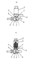
- FIGs. 1 - 4 are explanatory drawings to show the steps of the present invention using a molding machine suitable to execute this invention.
- a match plate 3 is introduced between an upper flask 1 and a lower flask 2. Then, as shown in Fig. 2, the upper flask 1, the match plate 3, and an upper squeeze plate 4, are lowered to superimpose the match plate 3 and upper flask 1 on the lower flask 2. Then, as shown in Fig.
- the superimposed upper and lower flasks 1, 2 and match plate 3 are rotated by a rotary device 10 through 90° about a horizontal axis of rotation to connect two blow-in ports 5, 5 of the upper and lower flasks 1, 2 with blow-off ports 6, 6 of a blow head 7, and a lower squeeze plate 8 is inserted just a little into an end opening of the lower flask 2.
- a device that defines a mold space comprising the upper and lower flasks 1, 2, match plate 3, and upper and lower squeeze plates 4, 8, defines a mold space 9.
- a predetermined amount of molding sand S is then supplied into the empty blow head 7. Although a part of the molding sand S flows out of the blow-off ports 6, 6 of the blow head 7, it enters the device (i.e., mold space 9) through the blow-in ports 5, 5. Thus it is not scattered outside the blow-off ports. Compressed air is then supplied into the blow head 7 by a known means (not shown) to blow the molding sand in the blow head 7 into the mold space, and the molding sand in the mold space is then squeezed by the upper and lower squeeze plates 4, 8. Thus a cope and a drag are produced by this molding machine in the normal molding operation.
Landscapes
- Engineering & Computer Science (AREA)
- Mechanical Engineering (AREA)
- Casting Devices For Molds (AREA)
Description
- This invention relates to a method of blow charging molding sand by means of compressed air into a blow head of a blow type molding machine as defined in the preamble of the appended claim.
- Such a method and machine is known from
JP-A-7-16 705 EP 0 465 930 A2 ) where molding sand is blow charged by means of compressed air into the device that defines a mold space, a part of the molding sand flows out of the blow-off port, which is mounted an the lower part of a blow head, when the mold sand is supplied into the empty blow head, and is scattered outside, thereby contaminating the working environment. - This invention was created to resolve this drawback. Its purpose is to provide a method of supplying molding sand into a blow head wherein the molding sand does not flow out of a blow-off port when disconnected from the blow-in port of the device that defines the mold space and is prevented from being scattered when it is supplied to the blow head.
- To this end, In the method of the present invention of blow charging molding sand from a blow-off port of a blow head of a blow type molding machine into a blow-in port of a device that defines a mold space comprising (a) connecting the blow-off port of the blow head to the blow-in port of said device that defines a mold space in that the device is rotated about a horizontal axis such that the blow-in port of the device engages with the blow-off port of the blow head, (b) blowing molding sand contained In the blow head into the device through the blow-off and blow-in ports, and then (c) squeezing the molding sand in the mold space, the improvement that after step (a) a predetermined amount of molding sand is introduced into the blow head, and in that after a mold is produced to some degree the molding sand in the blow-off port of the blow head is hardened and blocks the blow-off port, so that after a first mold is produced molding sand does not flow out when it is supplied to the blow head.
- The device that defines the mold space can receive any of the molding sand which flows out of the blow-off port of the blow head when the molding sand is supplied into the blow head for the production of the first sand mold. Thus the part of the molding sand flowing out of the blow-off port is not scattered in the environment. Thereafter, molding sand does not flow out of the blow-off port when disconnected from the blow-in port of the device that defines the mold space.
- Figs. 1 - 4 are explanatory drawings to show the steps of the present invention using a molding machine suitable to execute this invention.
- By reference to Figs. 1 - 4 the preferred embodiment of the present invention is now explained. As shown in Fig. 1, a
match plate 3 is introduced between anupper flask 1 and alower flask 2. Then, as shown in Fig. 2, theupper flask 1, thematch plate 3, and anupper squeeze plate 4, are lowered to superimpose thematch plate 3 andupper flask 1 on thelower flask 2. Then, as shown in Fig. 3, the superimposed upper andlower flasks match plate 3 are rotated by arotary device 10 through 90° about a horizontal axis of rotation to connect two blow-inports lower flasks ports blow head 7, and alower squeeze plate 8 is inserted just a little into an end opening of thelower flask 2. A device that defines a mold space, comprising the upper andlower flasks match plate 3, and upper andlower squeeze plates mold space 9. - As shown in Fig. 4, a predetermined amount of molding sand S is then supplied into the
empty blow head 7. Although a part of the molding sand S flows out of the blow-offports blow head 7, it enters the device (i.e., mold space 9) through the blow-inports blow head 7 by a known means (not shown) to blow the molding sand in theblow head 7 into the mold space, and the molding sand in the mold space is then squeezed by the upper andlower squeeze plates - After a mold is produced in this way, since to some degree the molding sand in the blow-off ports of the
blow head 7 is hardened, it blocks the ports. Therefore, the molding sand in theblow head 7 does not flow out unless compressed air is supplied into it. Thus, after the first mold is produced, molding sand does not flow out when it is supplied to theblow head 7. - It is understood by those skilled in the art that the embodiment is exemplary, and this invention can be carried out in other modified forms without departing from the scope of the claims of the invention attached to this specification.
Claims (1)
- Method of blowing molding sand from a blow-off port of a blow head of a blow type molding machine into a blow-in port of a device that defines a mold space, comprising the steps of(a) connecting the blow-off port of the blow head to the blow-in port of said device that defines a mold space in that the device is rotated about a horizontal axis such that the blow-in port of the device engages with the blow-off port of the blow head,(b) blowing molding sand contained in the blow head into the device through the blow-off and blow-in ports, and then(c) squeezing the molding sand in the mold space,
characterized in that
after step (a) a predetermined amount of molding sand is introduced into the blow head, and in that
after a mold is produced to some degree the molding sand in the blow-off port of the blow head is hardened and blocks the blow-off port, so that after a first mold is produced molding sand does not flow out when it is supplied to the blow head.
Applications Claiming Priority (4)
| Application Number | Priority Date | Filing Date | Title |
|---|---|---|---|
| JP8110495A JPH09271897A (en) | 1996-04-05 | 1996-04-05 | Method for supplying sand into blow head in blow-in type molding machine |
| JP11049596 | 1996-04-05 | ||
| JP110495/96 | 1996-04-05 | ||
| PCT/JP1997/001056 WO1997037790A1 (en) | 1996-04-05 | 1997-03-27 | Method of supplying sand to blow head of blow type molding machine |
Publications (4)
| Publication Number | Publication Date |
|---|---|
| EP0836900A1 EP0836900A1 (en) | 1998-04-22 |
| EP0836900A4 EP0836900A4 (en) | 1998-05-20 |
| EP0836900B1 EP0836900B1 (en) | 2001-12-12 |
| EP0836900B2 true EP0836900B2 (en) | 2007-11-14 |
Family
ID=14537211
Family Applications (1)
| Application Number | Title | Priority Date | Filing Date |
|---|---|---|---|
| EP97914553A Expired - Lifetime EP0836900B2 (en) | 1996-04-05 | 1997-03-27 | Method of supplying sand to blow head of blow type molding machine |
Country Status (6)
| Country | Link |
|---|---|
| US (1) | US5927372A (en) |
| EP (1) | EP0836900B2 (en) |
| JP (1) | JPH09271897A (en) |
| CN (1) | CN1161198C (en) |
| DE (1) | DE69709020T3 (en) |
| WO (1) | WO1997037790A1 (en) |
Families Citing this family (8)
| Publication number | Priority date | Publication date | Assignee | Title |
|---|---|---|---|---|
| US8033316B2 (en) * | 2005-06-07 | 2011-10-11 | Sintokogio, Ltd. | Flask unit and cope-and-drag molding machine and line |
| BRPI0612037B1 (en) * | 2005-06-13 | 2015-08-04 | Sintokogio Ltd | Molding apparatus without molding box for upper and lower mold |
| EP1897635B1 (en) | 2005-06-13 | 2015-04-22 | Sintokogio, Ltd. | A method for making flaskless upper and lower molds, an apparatus therefor, and a method for placing a core. |
| DE102007026537A1 (en) | 2006-12-18 | 2007-11-29 | Sintokogio, Ltd., Nagoya | Molding machine for molding a pair of box-less casting molds comprises molding boxes, an exchangeable model plate, a device for moving the boxes, pressing parts, a support device and adjusting drives for moving the pressing parts |
| US7762307B2 (en) * | 2007-01-16 | 2010-07-27 | Sintokogio Ltd. | Sand-introducing device using air, and method and apparatus for producing a mold |
| US7681624B2 (en) * | 2007-05-25 | 2010-03-23 | Sintokogio, Ltd. | Flaskless molding machine |
| JP6468243B2 (en) | 2016-05-17 | 2019-02-13 | 新東工業株式会社 | Frame making machine |
| JP6468242B2 (en) | 2016-05-17 | 2019-02-13 | 新東工業株式会社 | Frame making machine |
Citations (2)
| Publication number | Priority date | Publication date | Assignee | Title |
|---|---|---|---|---|
| JPS56168935A (en) † | 1980-05-27 | 1981-12-25 | Sintokogio Ltd | Method and device for blowing of casting sand |
| JPH0716705A (en) † | 1993-07-02 | 1995-01-20 | Sintokogio Ltd | Horizontal cutting frame mold making equipment |
Family Cites Families (10)
| Publication number | Priority date | Publication date | Assignee | Title |
|---|---|---|---|---|
| US3089207A (en) * | 1959-04-09 | 1963-05-14 | Osborn Mfg Co | Blow-squeeze molding machine |
| US3730250A (en) * | 1969-01-09 | 1973-05-01 | H Fellows | Method of making a sand mold |
| JPS5213425A (en) * | 1975-07-23 | 1977-02-01 | Sintokogio Ltd | Method of forming mold |
| JPS5220928A (en) * | 1975-08-12 | 1977-02-17 | Sintokogio Ltd | Prow squeeze machine |
| JPS5317083A (en) * | 1976-07-30 | 1978-02-16 | Kanematsu Semi Conductor | Semiconductor device |
| JPS5317084A (en) * | 1976-07-30 | 1978-02-16 | Hitachi Ltd | Buried hetero type semiconductor laser device |
| JP2772854B2 (en) * | 1990-06-29 | 1998-07-09 | 新東工業株式会社 | Casting sand filling method |
| JP2772859B2 (en) * | 1990-07-27 | 1998-07-09 | 新東工業株式会社 | Frameless mold making machine |
| DE4033887C2 (en) * | 1990-10-25 | 1994-07-28 | Hottinger Adolf Masch | Device and method for producing molded parts for foundry purposes |
| JPH05277635A (en) * | 1992-03-31 | 1993-10-26 | Isuzu Motors Ltd | Method for removing sand in cold box molding machine |
-
1996
- 1996-04-05 JP JP8110495A patent/JPH09271897A/en active Pending
-
1997
- 1997-03-27 DE DE69709020T patent/DE69709020T3/en not_active Expired - Lifetime
- 1997-03-27 CN CNB971903212A patent/CN1161198C/en not_active Expired - Lifetime
- 1997-03-27 EP EP97914553A patent/EP0836900B2/en not_active Expired - Lifetime
- 1997-03-27 US US08/973,330 patent/US5927372A/en not_active Expired - Lifetime
- 1997-03-27 WO PCT/JP1997/001056 patent/WO1997037790A1/en not_active Ceased
Patent Citations (2)
| Publication number | Priority date | Publication date | Assignee | Title |
|---|---|---|---|---|
| JPS56168935A (en) † | 1980-05-27 | 1981-12-25 | Sintokogio Ltd | Method and device for blowing of casting sand |
| JPH0716705A (en) † | 1993-07-02 | 1995-01-20 | Sintokogio Ltd | Horizontal cutting frame mold making equipment |
Also Published As
| Publication number | Publication date |
|---|---|
| DE69709020T2 (en) | 2002-05-02 |
| CN1188435A (en) | 1998-07-22 |
| WO1997037790A1 (en) | 1997-10-16 |
| US5927372A (en) | 1999-07-27 |
| DE69709020T3 (en) | 2008-03-13 |
| EP0836900A4 (en) | 1998-05-20 |
| CN1161198C (en) | 2004-08-11 |
| DE69709020D1 (en) | 2002-01-24 |
| EP0836900B1 (en) | 2001-12-12 |
| JPH09271897A (en) | 1997-10-21 |
| EP0836900A1 (en) | 1998-04-22 |
Similar Documents
| Publication | Publication Date | Title |
|---|---|---|
| EP0836900B1 (en) | Method of supplying sand to blow head of blow type molding machine | |
| CN105855506B (en) | The expects pipe component and injection mold device of the anti-volume gas of die casting machine | |
| US4791974A (en) | Method and an apparatus for producing shaped bodies from particulate material | |
| CN109641267A (en) | Casting system | |
| CN105921626B (en) | A kind of more moving mold devices and its manufacture method | |
| US5915451A (en) | Casting core fabrication apparatus | |
| EP1952912B1 (en) | Molding machine and molding method | |
| CN213997751U (en) | Aluminum alloy wheel low pressure casting spreader cone | |
| CN208162551U (en) | Aluminum casting mixes movement system with sand | |
| CN219909999U (en) | Small-sized fine stone concrete conveying pump | |
| CN108339940A (en) | Running gate system and casting mold for manufacturing compresser cylinder casting | |
| GB1404052A (en) | Methods of operating automatic mould part producing apparatus and apparatuses for carrying out these methods | |
| US20250083217A1 (en) | Core molding system and method | |
| CN220463550U (en) | Pin-connected panel mould for resin pouring | |
| CN216359304U (en) | Die casting die structure with central feeding sprue | |
| CN211660423U (en) | Casting solvent filtering device | |
| CN215090535U (en) | Hydraulic press casting precision mold convenient for exhausting | |
| CN109571956A (en) | A kind of 3D printer rotation switching nozzle mechanism | |
| KR100921805B1 (en) | Molding Vent Processing Equipment | |
| JPH0466253A (en) | Side die clamping vertical casting type die casting machine | |
| EP0175833A2 (en) | Die-casting apparatus for die-casting non ferrous alloys, in particular brass, with a low pressure process | |
| CN208451137U (en) | The clamping device for processing of casting | |
| JP3518969B2 (en) | Mold core molding method and molding apparatus | |
| CN2370980Y (en) | Screw vibration used sand regenerator | |
| JPS62101361A (en) | Applying method for release agent for rotor die casting |
Legal Events
| Date | Code | Title | Description |
|---|---|---|---|
| PUAI | Public reference made under article 153(3) epc to a published international application that has entered the european phase |
Free format text: ORIGINAL CODE: 0009012 |
|
| 17P | Request for examination filed |
Effective date: 19971205 |
|
| AK | Designated contracting states |
Kind code of ref document: A1 Designated state(s): DE FR GB |
|
| RHK1 | Main classification (correction) |
Ipc: B22C 15/28 |
|
| A4 | Supplementary search report drawn up and despatched | ||
| AK | Designated contracting states |
Kind code of ref document: A4 Designated state(s): DE FR GB |
|
| 17Q | First examination report despatched |
Effective date: 19991124 |
|
| GRAG | Despatch of communication of intention to grant |
Free format text: ORIGINAL CODE: EPIDOS AGRA |
|
| GRAG | Despatch of communication of intention to grant |
Free format text: ORIGINAL CODE: EPIDOS AGRA |
|
| GRAH | Despatch of communication of intention to grant a patent |
Free format text: ORIGINAL CODE: EPIDOS IGRA |
|
| GRAG | Despatch of communication of intention to grant |
Free format text: ORIGINAL CODE: EPIDOS AGRA |
|
| GRAH | Despatch of communication of intention to grant a patent |
Free format text: ORIGINAL CODE: EPIDOS IGRA |
|
| GRAH | Despatch of communication of intention to grant a patent |
Free format text: ORIGINAL CODE: EPIDOS IGRA |
|
| GRAA | (expected) grant |
Free format text: ORIGINAL CODE: 0009210 |
|
| AK | Designated contracting states |
Kind code of ref document: B1 Designated state(s): DE FR GB |
|
| REG | Reference to a national code |
Ref country code: GB Ref legal event code: IF02 |
|
| REF | Corresponds to: |
Ref document number: 69709020 Country of ref document: DE Date of ref document: 20020124 |
|
| ET | Fr: translation filed | ||
| PLBQ | Unpublished change to opponent data |
Free format text: ORIGINAL CODE: EPIDOS OPPO |
|
| PLBI | Opposition filed |
Free format text: ORIGINAL CODE: 0009260 |
|
| PLBF | Reply of patent proprietor to notice(s) of opposition |
Free format text: ORIGINAL CODE: EPIDOS OBSO |
|
| 26 | Opposition filed |
Opponent name: DISA INDUSTRIES A/S Effective date: 20020911 |
|
| PLBF | Reply of patent proprietor to notice(s) of opposition |
Free format text: ORIGINAL CODE: EPIDOS OBSO |
|
| PLBF | Reply of patent proprietor to notice(s) of opposition |
Free format text: ORIGINAL CODE: EPIDOS OBSO |
|
| RDAF | Communication despatched that patent is revoked |
Free format text: ORIGINAL CODE: EPIDOSNREV1 |
|
| APBP | Date of receipt of notice of appeal recorded |
Free format text: ORIGINAL CODE: EPIDOSNNOA2O |
|
| APBM | Appeal reference recorded |
Free format text: ORIGINAL CODE: EPIDOSNREFNO |
|
| APBQ | Date of receipt of statement of grounds of appeal recorded |
Free format text: ORIGINAL CODE: EPIDOSNNOA3O |
|
| APAH | Appeal reference modified |
Free format text: ORIGINAL CODE: EPIDOSCREFNO |
|
| APBU | Appeal procedure closed |
Free format text: ORIGINAL CODE: EPIDOSNNOA9O |
|
| PUAH | Patent maintained in amended form |
Free format text: ORIGINAL CODE: 0009272 |
|
| STAA | Information on the status of an ep patent application or granted ep patent |
Free format text: STATUS: PATENT MAINTAINED AS AMENDED |
|
| 27A | Patent maintained in amended form |
Effective date: 20071114 |
|
| AK | Designated contracting states |
Kind code of ref document: B2 Designated state(s): DE FR GB |
|
| ET3 | Fr: translation filed ** decision concerning opposition | ||
| REG | Reference to a national code |
Ref country code: FR Ref legal event code: PLFP Year of fee payment: 20 |
|
| PGFP | Annual fee paid to national office [announced via postgrant information from national office to epo] |
Ref country code: GB Payment date: 20160329 Year of fee payment: 20 |
|
| PGFP | Annual fee paid to national office [announced via postgrant information from national office to epo] |
Ref country code: DE Payment date: 20160329 Year of fee payment: 20 |
|
| PGFP | Annual fee paid to national office [announced via postgrant information from national office to epo] |
Ref country code: FR Payment date: 20160329 Year of fee payment: 20 |
|
| REG | Reference to a national code |
Ref country code: DE Ref legal event code: R071 Ref document number: 69709020 Country of ref document: DE |
|
| REG | Reference to a national code |
Ref country code: GB Ref legal event code: PE20 Expiry date: 20170326 |
|
| PG25 | Lapsed in a contracting state [announced via postgrant information from national office to epo] |
Ref country code: GB Free format text: LAPSE BECAUSE OF EXPIRATION OF PROTECTION Effective date: 20170326 |