EP0836665B1 - Wall structures for swimming pools - Google Patents
Wall structures for swimming pools Download PDFInfo
- Publication number
- EP0836665B1 EP0836665B1 EP96918565A EP96918565A EP0836665B1 EP 0836665 B1 EP0836665 B1 EP 0836665B1 EP 96918565 A EP96918565 A EP 96918565A EP 96918565 A EP96918565 A EP 96918565A EP 0836665 B1 EP0836665 B1 EP 0836665B1
- Authority
- EP
- European Patent Office
- Prior art keywords
- panel
- weakening
- lines
- peripheral edge
- apertures
- Prior art date
- Legal status (The legal status is an assumption and is not a legal conclusion. Google has not performed a legal analysis and makes no representation as to the accuracy of the status listed.)
- Expired - Lifetime
Links
- 230000009182 swimming Effects 0.000 title description 4
- 230000003313 weakening effect Effects 0.000 claims description 18
- 230000002093 peripheral effect Effects 0.000 claims description 12
- 230000003014 reinforcing effect Effects 0.000 claims description 11
- 239000000463 material Substances 0.000 claims description 5
- 239000004616 structural foam Substances 0.000 claims description 5
- 239000004743 Polypropylene Substances 0.000 claims description 3
- -1 polypropylene Polymers 0.000 claims description 3
- 229920001155 polypropylene Polymers 0.000 claims description 3
- 230000003292 diminished effect Effects 0.000 claims description 2
- 239000006260 foam Substances 0.000 claims 1
- 239000004567 concrete Substances 0.000 description 5
- 238000010276 construction Methods 0.000 description 3
- 238000005452 bending Methods 0.000 description 2
- 238000012986 modification Methods 0.000 description 2
- 230000004048 modification Effects 0.000 description 2
- 230000004075 alteration Effects 0.000 description 1
- 230000010485 coping Effects 0.000 description 1
- 238000009434 installation Methods 0.000 description 1
- 230000013011 mating Effects 0.000 description 1
- 239000011378 shotcrete Substances 0.000 description 1
- 125000006850 spacer group Chemical group 0.000 description 1
- 239000000126 substance Substances 0.000 description 1
- 239000000758 substrate Substances 0.000 description 1
Images




Classifications
-
- E—FIXED CONSTRUCTIONS
- E04—BUILDING
- E04H—BUILDINGS OR LIKE STRUCTURES FOR PARTICULAR PURPOSES; SWIMMING OR SPLASH BATHS OR POOLS; MASTS; FENCING; TENTS OR CANOPIES, IN GENERAL
- E04H4/00—Swimming or splash baths or pools
- E04H4/0018—Easily movable or transportable swimming pools
- E04H4/0043—Easily movable or transportable swimming pools mainly made of panels
Definitions
- the present invention relates to a panel suitable for forming a side wall of an inground pool.
- Inground swimming pools can be formed to have a variety of different structures. These structures range from a full concrete pool wherein the concrete is poured or sprayed (gunite), to other more recent types of structures wherein the base of the pool is formed of concrete and is then covered with a liner which covers the base and a wall structure.
- the use of prefabricated walls has started to become more popular since this can both be a more economical arrangement while also allowing for flexibility in the pool structure.
- Document AU-B-522 393 discloses a panel suitable for forming a side wall of an inground pool having the features of the preamble of claim 1.
- a panel which is suitable for forming the side wall of an inground pool, the panel having a front face, a rear face, an upper peripheral edge, a bottom peripheral edge and side peripheral edges.
- the front face is the one which faces inwardly to the pool and as such, has a substantially continuous surface.
- the rear face has a plurality of reinforcing flanges extending outwardly therefrom while there are also provided a plurality of lines of weakening which extend substantially vertically between the upper peripheral edge and the bottom peripheral edge to thereby permit flexing of the panel.
- the lines of weakening comprise areas of diminished wall thickness.
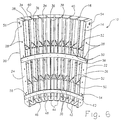
- Panel 10 has a front face 12 and a rear face 14.
- the panel is bounded by an upper edge 16, a lower edge 18 and side edges 20 and 22 extending between upper edge 16 and lower edge 18.
- Located at side edge 20 is a rearwardly extending side wall 24 and similarly, adjacent side edge 22 is a rearwardly extending side wall 26.
- Both side walls 24 and 26 have a plurality of apertures 28 formed therein.
- intermediate vertical flanges 30 are a plurality of vertically extending grooves 32 which form lines of weakening.
- panel 10 has a thickness which is less at grooves 32 than the standard wall thickness.
- upper flange elements 34 Extending rearwardly from upper edge 16 are a plurality of upper flange elements generally designated by reference numeral 34.
- Each upper flange element 34 has a distal end 36 with side edges 38 and 40.
- upper flange elements 34 have a generally trapezoidal configuration with sides 38 and 40 tapering inwardly towards each other as they extend to distal end 36.
- the panel also includes lower flange elements 42 (see Figure 3) which, like upper flange elements 34, have a generally trapezoidal configuration with sides 46 and 48 tapering inwardly to distal end 44.
- the panel may be bent in the standard radius configuration as shown in Figures 5 and 7 to provide an arcuate concave configuration for front face 12.
- the grooves 32 or lines of weakening also will permit bending of the panel in a reverse radius configuration as shown in Figures 4 and 6 to have a convex configuration.
- the tapered edges of the upper flange elements 34 and lower flange elements 42 allow panel 10 to assume the reverse radius configuration.
- vertical flanges 30 have vertical flange apertures 50 formed therein.
- a plurality of reinforcing elements or gussets 52 are formed and which elements extend between vertical flanges 30 and rear face 14.
- side wall 28 includes upper and lower locating lugs 54. Locating lugs 54 are adapted to mate with locating apertures 56 in an adjacent side wall such as is shown in side wall 24.
- an upper strap member 58 and a lower strap member 60 each of which has apertures 62 formed therein.
- the arrangement is such that a fastening device is adapted to fit through an aperture 62 in upper strap 58 and through vertical flange apertures 50. Suitable mechanical fastening means such as screws 70 may be utilized.
- a fastening element 64 (see Figure 8) also having an aperture 66 therein may be utilized.
- a plurality of reinforcing elements or gussets 68 are provided adjacent the side walls and rear face such as shown in Figure 8.
- a tab 72 may be formed on the distal end of the flange adjacent wall 26 with a corresponding recess 74 formed at upper edges 16. Tab 72 is adapted to mate with recess 74 on an adjacent panel when the panels are in a stacked arrangement.
- the panel may be formed of several different materials although a structural foam material is preferably used for these types of structures.
- a polypropylene structural foam is suitable although any material having the required strength and rigidity and which can be adapted for the purposes of the present invention could be used.
- the lines of weakening 32 which extend in a vertical direction, permit the flexing of the panel into different configurations.
- One means of providing the lines of weakening is to have a reduced panel thickness at the areas of the lines of weakening to permit the flexing thereof.
- a material such as a polypropylene structural foam
- the number of lines of weakening can vary and it is well within the skill of those knowledgeable in the art to calculate a desirable number given the end purpose.
- the spacing between the lines of weakening may be between 1.25 and 20 cm (1/2 and 8 inches) and preferably between 5 and 15 cm (2 and 6 inches).
- reinforcing means which usually comprise ribs or flanges, but may comprise additional ribs or flanges, as desired.
- reinforcing means which usually comprise ribs or flanges, but may comprise additional ribs or flanges, as desired.
- the upper flange elements 34 can be used for attaching and supporting the pool coping, while the lower flange elements 42 can be used to attach the panel member to a substrate which may be the bottom of the pool, or be anchored in concrete around the base of panel 10.
- the upper and lower flanges must have means to permit flexing or bending of the wall panel in both the concave and convex configurations and to this end, the upper and lower flanges are preferably divided into a plurality of flange elements as described above, but they could have other configurations as well.
- strap members 58, 60 and fasteners 70 are means for securing the panel in its desired configuration.
- securing members or straps which will extend transversely along the rear face of the panel, and which have other means for being secured to the panel, and the securing members or straps can be located in other positions, such as adjacent to flanges 34 or 42.
- the vertically extending reinforcing flanges 30 have apertures formed therein adapted to receive a mechanical fastener such as a screw 70 or the like.
- the reinforcing members or straps 58, 60 likewise have a plurality of apertures formed therein, the apertures being spaced apart a distance according to the desired curvature of the panel. In other words, as the panels are flexed into a desired configuration, the distance between the vertical reinforcing flanges or ribs 30 will vary. By correctly calculating these distances, the reinforcing straps 58, 60 can have apertures spaced apart by a distance which would correspond to the desired curvature or lack thereof. As will be appreciated, one could readily envisage an arrangement wherein a pool designer could design a free form pool and at the same time, generate the spacing between the apertures. By so doing, installation using the panels of the present invention would be simplified.
- panels 10 can be made straight or flat, curved panels 10 can be used with conventional mating rigid straight panels as well. Also, narrow spacers or wedges can be used between adjacent panels or between curved and straight panels, as will be apparent to those skilled in the art. Further, the lines of weakening and flanges 30 could be orientated differently, such as horizontally, so that the panels curve about a horizontal or some other axis, if desired.
Landscapes
- Engineering & Computer Science (AREA)
- Architecture (AREA)
- Civil Engineering (AREA)
- Structural Engineering (AREA)
- Finishing Walls (AREA)
- Rigid Containers With Two Or More Constituent Elements (AREA)
- Joining Of Building Structures In Genera (AREA)
- Underground Structures, Protecting, Testing And Restoring Foundations (AREA)
Description
Claims (11)
- A panel (10) suitable for forming a side wall of an inground pool, the panel having a front face (12), a rear face (14), an upper peripheral edge (16), a bottom peripheral edge (18), and side peripheral edges (20, 22), characterized by said front face (12) having a substantially continuous surface, a plurality of reinforcing flanges (30) extending outwardly from said rear face (14), and a plurality of lines of weakening extending substantially vertically between said upper peripheral edge (16) and said bottom peripheral edge (18) thereby to permit flexing of said panel (10), said lines of weakening comprising areas of diminished wall thickness.
- The panel of claim 1 wherein said lines of weakening are substantially parallel.
- The panel of claim 2 wherein said lines of weakening are spaced apart a distance of between 5 and 15 cm (2 and 6 inches).
- The panel of claim 2 wherein said reinforcing flanges are evenly spaced between said lines of weakening.
- The panel of claim 2 further including a plurality of upper flange elements extending from said upper peripheral edge and a plurality of bottom flange elements extending outwardly from said bottom peripheral edge.
- The panel of claim 5 wherein said upper flange elements and said lower flange elements each have a general trapezoidal configuration with said elements extending from between said lines of weakening rearwardly and having inwardly tapering walls to a distal end thereof.
- The panel of claim 2 further including means for securing said panel in an arcuate position.
- The panel of claim 7 wherein said means comprises a transversely extending member adapted to be secured to said vertical flanges.
- The panel of claim 8 wherein said vertical flanges have apertures formed therein, said securing means comprising spaced apart apertures in said transversely extending member and mechanical fastening means extending through said transversely extending member apertures into said vertical flange apertures.
- The panel of claim 1 wherein said panel is formed of a structural foam material.
- The panel of claim 10 wherein said structural foam is a polypropylene foam.
Applications Claiming Priority (3)
| Application Number | Priority Date | Filing Date | Title |
|---|---|---|---|
| US498576 | 1995-07-06 | ||
| US08/498,576 US5590493A (en) | 1995-07-06 | 1995-07-06 | Wall structures for swimming pools |
| PCT/CA1996/000424 WO1997002398A1 (en) | 1995-07-06 | 1996-06-21 | Wall structures for swimming pools |
Publications (2)
| Publication Number | Publication Date |
|---|---|
| EP0836665A1 EP0836665A1 (en) | 1998-04-22 |
| EP0836665B1 true EP0836665B1 (en) | 2000-11-08 |
Family
ID=23981632
Family Applications (1)
| Application Number | Title | Priority Date | Filing Date |
|---|---|---|---|
| EP96918565A Expired - Lifetime EP0836665B1 (en) | 1995-07-06 | 1996-06-21 | Wall structures for swimming pools |
Country Status (8)
| Country | Link |
|---|---|
| US (1) | US5590493A (en) |
| EP (1) | EP0836665B1 (en) |
| JP (1) | JP3040174B2 (en) |
| AU (1) | AU6119896A (en) |
| CA (1) | CA2238480C (en) |
| DE (1) | DE69610921T2 (en) |
| ES (1) | ES2151664T3 (en) |
| WO (1) | WO1997002398A1 (en) |
Families Citing this family (34)
| Publication number | Priority date | Publication date | Assignee | Title |
|---|---|---|---|---|
| US5975482A (en) * | 1997-07-21 | 1999-11-02 | Willian Holding Company | Concrete form having adjustable curvature |
| US6012699A (en) * | 1997-07-21 | 2000-01-11 | Wu; Edward | Concrete form having adjustable curvature |
| US6128878A (en) * | 1998-05-08 | 2000-10-10 | Erickson; Dayle Eugene | Portable storage building with concrete floor and method of assembling and moving same |
| JP3153172B2 (en) | 1998-06-09 | 2001-04-03 | セイコーインスツルメンツ株式会社 | Electronic clock and display method |
| US6094877A (en) * | 1998-08-24 | 2000-08-01 | White; Charles L. | Frame support assembly and method for curved walls |
| US6722091B1 (en) * | 1998-12-18 | 2004-04-20 | Robert J. Leslie | Residential homes having tensioned curved wall panels |
| CA2290791A1 (en) * | 1999-11-18 | 2001-05-18 | Yves Lecours | Prefabricated curved profile architectural element and method for fabricating the same |
| US7784223B1 (en) * | 2000-05-31 | 2010-08-31 | Ramey Larry E | Three hundred mile per hour wind resistive building |
| US6655100B1 (en) | 2001-04-16 | 2003-12-02 | Jose R. Andino | Framing assembly and method for the formation of a curved wall or like structure |
| FR2826036B1 (en) * | 2001-06-13 | 2003-09-12 | Albatica Sa | METHOD OF FORMING A MODULAR METAL STRUCTURE FOR THE CONSTRUCTION OF IN-GROUND POOLS |
| US6758025B2 (en) * | 2001-09-19 | 2004-07-06 | Gerhard Haberler | Method of forming a swimming pool construction |
| US6915612B2 (en) * | 2002-02-11 | 2005-07-12 | Brett Oakley | Window well with increased in-ground stability |
| AU4235802A (en) * | 2002-05-20 | 2003-11-27 | Andreas Krumbacher | Combinations flexible apparatus (multiple flexibletrack) |
| US7210271B2 (en) * | 2002-09-17 | 2007-05-01 | Flexability Concepts Llc | Header apparatus and method for a structural framing system |
| US7146773B2 (en) * | 2002-11-12 | 2006-12-12 | Kafko Canada Inc. | Concrete accepting wall structure with adjustable curvature |
| US7401440B2 (en) * | 2003-03-29 | 2008-07-22 | Hauck Robert F | Large, transportable arcuate architectural components |
| FR2856332B1 (en) * | 2003-06-20 | 2007-03-23 | Piscines Desjoyaux Sa | PANEL FOR REALIZING A SWIMMING POOL |
| US7131544B1 (en) * | 2003-07-09 | 2006-11-07 | Long-Stanton Manufacturing Co., Inc. | Wall conforming wine rack for a plurality of bottles |
| US7412802B2 (en) * | 2003-11-05 | 2008-08-19 | Caravelle International, Inc. | Swimming pool formed of interconnecting panels with supporting buttresses |
| US7210664B2 (en) * | 2004-08-06 | 2007-05-01 | Wilian Holding Company | Concrete form having adjustable curvature |
| US20070144082A1 (en) * | 2005-12-22 | 2007-06-28 | Paul Kantor | Pool having curvable wall |
| US20090057533A1 (en) * | 2006-02-08 | 2009-03-05 | Sunil Construction Co., Ltd. | Form panel for construction |
| EA200601384A1 (en) * | 2006-08-02 | 2008-02-28 | Виктор Вениаминович Константинов | SWIMMING POOL |
| FR2932514B1 (en) * | 2008-06-16 | 2013-04-05 | I T P Services | BASIN, SUCH AS SWIMMING POOL. |
| EP2635746A4 (en) * | 2010-10-19 | 2014-08-20 | Brafford Ralph | FORM FOR MANUFACTURING STRUCTURES |
| EP2530221A3 (en) * | 2011-06-01 | 2013-01-02 | Jo-Co Pools Inc. | Pool liner retaining system |
| US8869484B2 (en) | 2012-11-13 | 2014-10-28 | Usg Interiors, Llc | Flexible drywall grid member for framing drywall structures |
| FR3053373B1 (en) * | 2016-07-01 | 2020-07-10 | Piscines Desjoyaux Sa | MODULAR PANEL FOR FORMING THE WALLS OF A BASIN |
| US9903129B1 (en) * | 2017-01-26 | 2018-02-27 | Yvon Boutin | Insulating panels for above ground swimming pool |
| RU202688U1 (en) * | 2019-12-16 | 2021-03-02 | Денис Викентьевич Андрушкевич | POLYPROPYLENE FIXED FORMWORK FOR MANUFACTURING POOL WALLS |
| JP7407147B2 (en) | 2021-05-07 | 2023-12-28 | 任天堂株式会社 | Electronic equipment, electronic equipment control program |
| IT202200006710A1 (en) | 2022-04-05 | 2023-10-05 | Michele Chiarantoni | SYSTEM FOR TRAINING THE GAME OF TENNIS |
| CN117071889B (en) * | 2023-08-14 | 2025-11-14 | 中铁七局集团有限公司 | A construction formwork for curved eaves of buildings |
| KR102875071B1 (en) * | 2025-02-14 | 2025-10-22 | (주)성일신소재 | Constructing type of combined swimming pool |
Family Cites Families (11)
| Publication number | Priority date | Publication date | Assignee | Title |
|---|---|---|---|---|
| US2197318A (en) * | 1937-04-21 | 1940-04-16 | Rumble Roy William | Adjustably curvable structural sheet |
| US2829081A (en) * | 1954-08-02 | 1958-04-01 | Sweem Ervin Clyde | Foldable draperies and methods of manufacture |
| US3974605A (en) * | 1974-06-10 | 1976-08-17 | Elcon Manufacturing Company Limited | Wall structure and swimming pool construction |
| AU522393B2 (en) * | 1976-12-15 | 1982-06-03 | Whitehead, B.J. | Reservoir or swimming pools |
| US4464802A (en) * | 1981-10-16 | 1984-08-14 | Robert L. Glonek | Structural foam swimming pool wall and brace and method of erecting same |
| US4566141A (en) * | 1983-06-06 | 1986-01-28 | Mahoney Morgan D | Swimming pool wall construction in pools of the type using a metal side wall |
| US4671028A (en) * | 1984-08-07 | 1987-06-09 | Figone Frank M | Intrinsically hinged load member |
| US4679763A (en) * | 1985-08-22 | 1987-07-14 | Economy Forms Corporation | Concrete form having adjustable curvature and method for producing same |
| US4915345A (en) * | 1987-12-18 | 1990-04-10 | Symons Corporation | Concrete forming system for curved walls |
| US5137251A (en) * | 1989-08-30 | 1992-08-11 | Economy Forms Corporation | Pour window for a concrete form |
| US5384998A (en) | 1991-01-04 | 1995-01-31 | Kokuyo Co., Ltd. | Curved panel |
-
1995
- 1995-07-06 US US08/498,576 patent/US5590493A/en not_active Expired - Fee Related
-
1996
- 1996-06-21 CA CA002238480A patent/CA2238480C/en not_active Expired - Fee Related
- 1996-06-21 DE DE69610921T patent/DE69610921T2/en not_active Expired - Fee Related
- 1996-06-21 AU AU61198/96A patent/AU6119896A/en not_active Abandoned
- 1996-06-21 WO PCT/CA1996/000424 patent/WO1997002398A1/en not_active Ceased
- 1996-06-21 ES ES96918565T patent/ES2151664T3/en not_active Expired - Lifetime
- 1996-06-21 EP EP96918565A patent/EP0836665B1/en not_active Expired - Lifetime
- 1996-06-21 JP JP09504663A patent/JP3040174B2/en not_active Expired - Fee Related
Also Published As
| Publication number | Publication date |
|---|---|
| US5590493A (en) | 1997-01-07 |
| WO1997002398A1 (en) | 1997-01-23 |
| AU6119896A (en) | 1997-02-05 |
| ES2151664T3 (en) | 2001-01-01 |
| DE69610921T2 (en) | 2001-06-07 |
| CA2238480C (en) | 2002-01-01 |
| JP3040174B2 (en) | 2000-05-08 |
| JPH10510338A (en) | 1998-10-06 |
| DE69610921D1 (en) | 2000-12-14 |
| EP0836665A1 (en) | 1998-04-22 |
| CA2238480A1 (en) | 1997-01-23 |
Similar Documents
| Publication | Publication Date | Title |
|---|---|---|
| CA2238480C (en) | Wall structures for swimming pools | |
| US3869736A (en) | Collapsible swimming pool | |
| US3440780A (en) | Swimming pool wall construction | |
| US4918899A (en) | Building frame construction | |
| US4918765A (en) | Portable toilet cabana | |
| US4848046A (en) | Buildings for harsh environments | |
| US4167084A (en) | Swimming pool wall system | |
| US4831671A (en) | Portable toilet cabana | |
| US20030213195A1 (en) | Radius corner plate for a pool | |
| EP1420121A2 (en) | Concrete accepting wall structure with adjustable curvature | |
| KR100206031B1 (en) | Elevator cabin | |
| US4115977A (en) | Method of erecting swimming pool structure | |
| US4008547A (en) | In-ground swimming pool | |
| US3317927A (en) | Swimming pool construction | |
| US5555574A (en) | Support for end wall and swimming pool cover | |
| EP0219262B1 (en) | Buildings for harsh environments | |
| US7774992B2 (en) | Tile and strut construction system for geodesic dome | |
| US20070144082A1 (en) | Pool having curvable wall | |
| GB2136287A (en) | Swimming pool construction | |
| CA1118552A (en) | Swimming pool integral structural wall brace system | |
| RU2164865C1 (en) | Method mould for manufacture of prestressed cambered panels - shells | |
| JPS6035510B2 (en) | Assembly pool with overflow groove | |
| CA1061054A (en) | Swimming pool construction | |
| CA1143108A (en) | Swimming pool construction | |
| CA2102864C (en) | End wall receptacle for electric cover mechanism |
Legal Events
| Date | Code | Title | Description |
|---|---|---|---|
| PUAI | Public reference made under article 153(3) epc to a published international application that has entered the european phase |
Free format text: ORIGINAL CODE: 0009012 |
|
| 17P | Request for examination filed |
Effective date: 19980123 |
|
| AK | Designated contracting states |
Kind code of ref document: A1 Designated state(s): DE ES FR IT |
|
| GRAG | Despatch of communication of intention to grant |
Free format text: ORIGINAL CODE: EPIDOS AGRA |
|
| 17Q | First examination report despatched |
Effective date: 20000202 |
|
| GRAG | Despatch of communication of intention to grant |
Free format text: ORIGINAL CODE: EPIDOS AGRA |
|
| GRAH | Despatch of communication of intention to grant a patent |
Free format text: ORIGINAL CODE: EPIDOS IGRA |
|
| GRAH | Despatch of communication of intention to grant a patent |
Free format text: ORIGINAL CODE: EPIDOS IGRA |
|
| GRAA | (expected) grant |
Free format text: ORIGINAL CODE: 0009210 |
|
| AK | Designated contracting states |
Kind code of ref document: B1 Designated state(s): DE ES FR IT |
|
| REF | Corresponds to: |
Ref document number: 69610921 Country of ref document: DE Date of ref document: 20001214 |
|
| REG | Reference to a national code |
Ref country code: ES Ref legal event code: FG2A Ref document number: 2151664 Country of ref document: ES Kind code of ref document: T3 |
|
| ITF | It: translation for a ep patent filed | ||
| ET | Fr: translation filed | ||
| PLBE | No opposition filed within time limit |
Free format text: ORIGINAL CODE: 0009261 |
|
| STAA | Information on the status of an ep patent application or granted ep patent |
Free format text: STATUS: NO OPPOSITION FILED WITHIN TIME LIMIT |
|
| 26N | No opposition filed | ||
| REG | Reference to a national code |
Ref country code: ES Ref legal event code: PC2A |
|
| PGFP | Annual fee paid to national office [announced via postgrant information from national office to epo] |
Ref country code: FR Payment date: 20060529 Year of fee payment: 11 |
|
| PGFP | Annual fee paid to national office [announced via postgrant information from national office to epo] |
Ref country code: ES Payment date: 20060627 Year of fee payment: 11 |
|
| PGFP | Annual fee paid to national office [announced via postgrant information from national office to epo] |
Ref country code: IT Payment date: 20060630 Year of fee payment: 11 |
|
| PGFP | Annual fee paid to national office [announced via postgrant information from national office to epo] |
Ref country code: DE Payment date: 20060818 Year of fee payment: 11 |
|
| REG | Reference to a national code |
Ref country code: FR Ref legal event code: ST Effective date: 20080229 |
|
| PG25 | Lapsed in a contracting state [announced via postgrant information from national office to epo] |
Ref country code: DE Free format text: LAPSE BECAUSE OF NON-PAYMENT OF DUE FEES Effective date: 20080101 |
|
| REG | Reference to a national code |
Ref country code: ES Ref legal event code: FD2A Effective date: 20070622 |
|
| PG25 | Lapsed in a contracting state [announced via postgrant information from national office to epo] |
Ref country code: FR Free format text: LAPSE BECAUSE OF NON-PAYMENT OF DUE FEES Effective date: 20070702 |
|
| PG25 | Lapsed in a contracting state [announced via postgrant information from national office to epo] |
Ref country code: ES Free format text: LAPSE BECAUSE OF NON-PAYMENT OF DUE FEES Effective date: 20070622 |
|
| PG25 | Lapsed in a contracting state [announced via postgrant information from national office to epo] |
Ref country code: IT Free format text: LAPSE BECAUSE OF NON-PAYMENT OF DUE FEES Effective date: 20070621 |