EP0836464B1 - Massaging device for insertion in the back of massage chairs or the like - Google Patents
Massaging device for insertion in the back of massage chairs or the like Download PDFInfo
- Publication number
- EP0836464B1 EP0836464B1 EP97916412A EP97916412A EP0836464B1 EP 0836464 B1 EP0836464 B1 EP 0836464B1 EP 97916412 A EP97916412 A EP 97916412A EP 97916412 A EP97916412 A EP 97916412A EP 0836464 B1 EP0836464 B1 EP 0836464B1
- Authority
- EP
- European Patent Office
- Prior art keywords
- axis
- shaft
- upper shaft
- lower shaft
- eccentric
- Prior art date
- Legal status (The legal status is an assumption and is not a legal conclusion. Google has not performed a legal analysis and makes no representation as to the accuracy of the status listed.)
- Expired - Lifetime
Links
- 238000003780 insertion Methods 0.000 title claims abstract description 6
- 230000037431 insertion Effects 0.000 title claims abstract description 6
- 230000033001 locomotion Effects 0.000 claims abstract description 17
- 230000009467 reduction Effects 0.000 claims description 4
- 230000010355 oscillation Effects 0.000 claims description 3
- 230000000284 resting effect Effects 0.000 claims description 2
- 230000005540 biological transmission Effects 0.000 description 8
- 238000010079 rubber tapping Methods 0.000 description 5
- 230000008901 benefit Effects 0.000 description 3
- 230000002860 competitive effect Effects 0.000 description 1
- 230000008878 coupling Effects 0.000 description 1
- 238000010168 coupling process Methods 0.000 description 1
- 238000005859 coupling reaction Methods 0.000 description 1
- 230000000694 effects Effects 0.000 description 1
- 238000004519 manufacturing process Methods 0.000 description 1
- 230000004048 modification Effects 0.000 description 1
- 238000012986 modification Methods 0.000 description 1
- 238000009527 percussion Methods 0.000 description 1
Images



Classifications
-
- A—HUMAN NECESSITIES
- A61—MEDICAL OR VETERINARY SCIENCE; HYGIENE
- A61H—PHYSICAL THERAPY APPARATUS, e.g. DEVICES FOR LOCATING OR STIMULATING REFLEX POINTS IN THE BODY; ARTIFICIAL RESPIRATION; MASSAGE; BATHING DEVICES FOR SPECIAL THERAPEUTIC OR HYGIENIC PURPOSES OR SPECIFIC PARTS OF THE BODY
- A61H15/00—Massage by means of rollers, balls, e.g. inflatable, chains, or roller chains
- A61H15/0078—Massage by means of rollers, balls, e.g. inflatable, chains, or roller chains power-driven
-
- A—HUMAN NECESSITIES
- A61—MEDICAL OR VETERINARY SCIENCE; HYGIENE
- A61H—PHYSICAL THERAPY APPARATUS, e.g. DEVICES FOR LOCATING OR STIMULATING REFLEX POINTS IN THE BODY; ARTIFICIAL RESPIRATION; MASSAGE; BATHING DEVICES FOR SPECIAL THERAPEUTIC OR HYGIENIC PURPOSES OR SPECIFIC PARTS OF THE BODY
- A61H7/00—Devices for suction-kneading massage; Devices for massaging the skin by rubbing or brushing not otherwise provided for
- A61H7/007—Kneading
-
- A—HUMAN NECESSITIES
- A61—MEDICAL OR VETERINARY SCIENCE; HYGIENE
- A61H—PHYSICAL THERAPY APPARATUS, e.g. DEVICES FOR LOCATING OR STIMULATING REFLEX POINTS IN THE BODY; ARTIFICIAL RESPIRATION; MASSAGE; BATHING DEVICES FOR SPECIAL THERAPEUTIC OR HYGIENIC PURPOSES OR SPECIFIC PARTS OF THE BODY
- A61H15/00—Massage by means of rollers, balls, e.g. inflatable, chains, or roller chains
- A61H2015/0007—Massage by means of rollers, balls, e.g. inflatable, chains, or roller chains with balls or rollers rotating about their own axis
- A61H2015/0028—Massage by means of rollers, balls, e.g. inflatable, chains, or roller chains with balls or rollers rotating about their own axis disc-like, i.e. diameter substantially greater than width
-
- A—HUMAN NECESSITIES
- A61—MEDICAL OR VETERINARY SCIENCE; HYGIENE
- A61H—PHYSICAL THERAPY APPARATUS, e.g. DEVICES FOR LOCATING OR STIMULATING REFLEX POINTS IN THE BODY; ARTIFICIAL RESPIRATION; MASSAGE; BATHING DEVICES FOR SPECIAL THERAPEUTIC OR HYGIENIC PURPOSES OR SPECIFIC PARTS OF THE BODY
- A61H2201/00—Characteristics of apparatus not provided for in the preceding codes
- A61H2201/01—Constructive details
- A61H2201/0119—Support for the device
- A61H2201/0138—Support for the device incorporated in furniture
-
- A—HUMAN NECESSITIES
- A61—MEDICAL OR VETERINARY SCIENCE; HYGIENE
- A61H—PHYSICAL THERAPY APPARATUS, e.g. DEVICES FOR LOCATING OR STIMULATING REFLEX POINTS IN THE BODY; ARTIFICIAL RESPIRATION; MASSAGE; BATHING DEVICES FOR SPECIAL THERAPEUTIC OR HYGIENIC PURPOSES OR SPECIFIC PARTS OF THE BODY
- A61H2201/00—Characteristics of apparatus not provided for in the preceding codes
- A61H2201/01—Constructive details
- A61H2201/0119—Support for the device
- A61H2201/0138—Support for the device incorporated in furniture
- A61H2201/0149—Seat or chair
-
- A—HUMAN NECESSITIES
- A61—MEDICAL OR VETERINARY SCIENCE; HYGIENE
- A61H—PHYSICAL THERAPY APPARATUS, e.g. DEVICES FOR LOCATING OR STIMULATING REFLEX POINTS IN THE BODY; ARTIFICIAL RESPIRATION; MASSAGE; BATHING DEVICES FOR SPECIAL THERAPEUTIC OR HYGIENIC PURPOSES OR SPECIFIC PARTS OF THE BODY
- A61H2201/00—Characteristics of apparatus not provided for in the preceding codes
- A61H2201/14—Special force transmission means, i.e. between the driving means and the interface with the user
- A61H2201/1427—Wobbling plate
-
- A—HUMAN NECESSITIES
- A61—MEDICAL OR VETERINARY SCIENCE; HYGIENE
- A61H—PHYSICAL THERAPY APPARATUS, e.g. DEVICES FOR LOCATING OR STIMULATING REFLEX POINTS IN THE BODY; ARTIFICIAL RESPIRATION; MASSAGE; BATHING DEVICES FOR SPECIAL THERAPEUTIC OR HYGIENIC PURPOSES OR SPECIFIC PARTS OF THE BODY
- A61H2201/00—Characteristics of apparatus not provided for in the preceding codes
- A61H2201/16—Physical interface with patient
- A61H2201/1602—Physical interface with patient kind of interface, e.g. head rest, knee support or lumbar support
- A61H2201/1623—Back
-
- A—HUMAN NECESSITIES
- A61—MEDICAL OR VETERINARY SCIENCE; HYGIENE
- A61H—PHYSICAL THERAPY APPARATUS, e.g. DEVICES FOR LOCATING OR STIMULATING REFLEX POINTS IN THE BODY; ARTIFICIAL RESPIRATION; MASSAGE; BATHING DEVICES FOR SPECIAL THERAPEUTIC OR HYGIENIC PURPOSES OR SPECIFIC PARTS OF THE BODY
- A61H2201/00—Characteristics of apparatus not provided for in the preceding codes
- A61H2201/16—Physical interface with patient
- A61H2201/1602—Physical interface with patient kind of interface, e.g. head rest, knee support or lumbar support
- A61H2201/1654—Layer between the skin and massage elements, e.g. fluid or ball
-
- A—HUMAN NECESSITIES
- A61—MEDICAL OR VETERINARY SCIENCE; HYGIENE
- A61H—PHYSICAL THERAPY APPARATUS, e.g. DEVICES FOR LOCATING OR STIMULATING REFLEX POINTS IN THE BODY; ARTIFICIAL RESPIRATION; MASSAGE; BATHING DEVICES FOR SPECIAL THERAPEUTIC OR HYGIENIC PURPOSES OR SPECIFIC PARTS OF THE BODY
- A61H2201/00—Characteristics of apparatus not provided for in the preceding codes
- A61H2201/16—Physical interface with patient
- A61H2201/1657—Movement of interface, i.e. force application means
- A61H2201/1664—Movement of interface, i.e. force application means linear
- A61H2201/1669—Movement of interface, i.e. force application means linear moving along the body in a reciprocating manner
-
- A—HUMAN NECESSITIES
- A61—MEDICAL OR VETERINARY SCIENCE; HYGIENE
- A61H—PHYSICAL THERAPY APPARATUS, e.g. DEVICES FOR LOCATING OR STIMULATING REFLEX POINTS IN THE BODY; ARTIFICIAL RESPIRATION; MASSAGE; BATHING DEVICES FOR SPECIAL THERAPEUTIC OR HYGIENIC PURPOSES OR SPECIFIC PARTS OF THE BODY
- A61H2201/00—Characteristics of apparatus not provided for in the preceding codes
- A61H2201/16—Physical interface with patient
- A61H2201/1657—Movement of interface, i.e. force application means
- A61H2201/1676—Pivoting
- A61H2201/1678—Means for angularly oscillating massage elements
-
- A—HUMAN NECESSITIES
- A61—MEDICAL OR VETERINARY SCIENCE; HYGIENE
- A61H—PHYSICAL THERAPY APPARATUS, e.g. DEVICES FOR LOCATING OR STIMULATING REFLEX POINTS IN THE BODY; ARTIFICIAL RESPIRATION; MASSAGE; BATHING DEVICES FOR SPECIAL THERAPEUTIC OR HYGIENIC PURPOSES OR SPECIFIC PARTS OF THE BODY
- A61H2205/00—Devices for specific parts of the body
- A61H2205/08—Trunk
- A61H2205/081—Back
Definitions
- the present invention relates to a massaging device for insertion in the back of massage chairs or the like.
- Conventional massaging devices for insertion in the back of massage chairs or the like generally comprise a frame which supports, so that they can rotate about their respective axes, an upper shaft and a lower shaft which are arranged so that their axes are parallel and substantially horizontal.
- the upper shaft and the lower shaft have, at their two opposite longitudinal ends, eccentric portions having a circular cross-section and which can be likened to cranks, each portion rotatably engaging an arm which supports, at its opposite end, a wheel which can rotate freely about its own axis, which is usually slightly inclined with respect to a horizontal direction which is parallel to the axes of the upper and of the lower shafts.
- Each one of the arms is pivoted, proximate to one of its intermediate portions, to an eccentric portion of the lower shaft which can also be likened to a crank.
- Each one of the arms is connected to the eccentric portion of the lower shaft by a linkage.
- the linkage is articulated in an intermediate point so as to allow to vary its useful length and connect it to the corresponding eccentric portion of the lower shaft by means of a spherical joint.
- the axis of the eccentric portions of the upper shaft which engage the arms is slightly inclined with respect to the axis of the upper shaft.
- the rotary actuation of the upper and of the lower shafts causes an oscillation of the wheels, which constitute the parts of the massaging device that act on the back of the user, about a respective axis which passes through the point where the axis of the corresponding eccentric portion of the upper shaft intersects the corresponding axis of the upper shaft; in other words, a movement in a horizontal direction occurs, thus producing the massage known as "stretching", and a vertical movement, producing the massage known as "tapping".
- the rotary actuation of the upper and of the lower shafts about their respective axes is achieved by means of a single motor which, by means of a belt drive, turns a transmission shaft arranged transversely to the upper and to the lower shafts and connected thereto by means of two pairs of helical gears.
- the helical gears arranged on the transmission shaft are connected to the transmission shaft by unidirectional bearings, i.e., bearings which can only rotate in one direction, allowing the corresponding gear to rotate freely with respect to the transmission shaft, and which lock in the opposite direction, rigidly rotationally coupling the corresponding gear to the transmission shaft.
- the bearing of one of the gears arranged on the transmission shaft rotates freely in one direction, whilst the bearing of the other gear arranged on the transmission shaft rotates freely in the opposite direction.
- the upper and lower shafts are rotated alternatively, the upper shaft producing the oscillating motion of the massage wheels, i.e., their movement in a substantially horizontal direction, the lower shaft moving the massage wheels substantially in a vertical direction.
- This device has the drawback of being very noisy during operation.
- the two stretching and tapping massage functions are performed separately.
- GB-A-1 400 473 discloses a massaging device as defined in the preamble of claim 1.
- US-A-5,464,382 discloses a massaging device with an electric motor for rotating a respective shaft to which a massage wheel is connected.
- US-A-5,052,376 discloses a drive section for automatic massaging apparatus arranged to smoothly effect operational switching for a pair of massaging rollers which carry out a massaging operation and a percussion operation.
- a principal aim of the present invention is to provide a massaging device which is very quiet during operation and which is compact.
- Another object of the present invention is to provide a massaging device which is practically maintenance-free.
- Another object of the present invention is to provide a massaging device wherein friction in the transmission of motion is minimized and which can use small and accordingly economical actuation motors.
- Another object of the present invention is to provide a massaging device which can be manufactured with competitive costs.
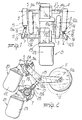
- the device according to the present invention comprises in a per se known manner a frame, not shown for the sake of simplicity, which supports, so that they can rotate about their respective axes 2a and 3a, an upper shaft 2 and a lower shaft 3 which are substantially parallel to each other and are arranged horizontally.
- the upper shaft 2 has, at its longitudinal ends, two eccentric portions 4 and 5 which have a circular transverse cross-section and can in practice be likened to cranks.
- the axes 4a and 5a of the eccentric portions 4 and 5 are inclined with respect to the axis 2a of the upper shaft 2.
- the eccentricity of the eccentric portions 4 and 5 is provided on a same side of the axis 2a of the upper shaft 2; i.e., the two eccentric portions 4 and 5 are in step with respect to each other.
- the lower shaft 3 has at its longitudinal ends two eccentric portions 6 and 7 which are also substantially circular and can be likened to two cranks.
- the eccentricity of the eccentric portion 6 is opposite to the eccentricity of the eccentric portion 7; i.e., the two eccentric portions 6 and 7 are angularly offset with respect to each other about the axis 3a of the lower shaft 3 by an angle of 180°.
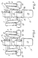
- the two eccentric portions of the lower shaft are constituted by two cams which are fixed to the lower shaft 3 proximate to its axial ends.
- Each cam 106 and 107 is substantially elliptical in transverse cross-section and the two cams are mounted on the shaft so as to be angularly offset, about the axis 3a, by an angle of substantially 90°.
- the device according to the present invention in its two embodiments, comprises two arms 8 and 9, each whereof rotatably supports a massage wheel 10 and 11 about its respective axis 10a and 11a.
- the arms 8 and 9 support the corresponding massage wheel 10 and 11 so that it can rotate freely at one of their ends and are pivoted, at their opposite end, to one of the eccentric portions 4 and 5 of the upper shaft 2.
- each arm 8 and 9 is connected, by means of an intermediate region of its extension, to one of the eccentric portions 6, 7, 106, 107 of the lower shaft 3.
- Each one of the arms 8 and 9, in the two embodiments, is arranged on a plane which is substantially perpendicular to the axis 4a, 5a of the corresponding eccentric portion 4, 5 of the upper shaft 2 to which they are connected.
- connection of the intermediate portion of each arm 8 and 9 to the corresponding eccentric portion 6 and 7 of the lower shaft 3 is provided by means of a linkage 12 and 13 which is pivoted, at one of its ends, to an intermediate portion of the corresponding arm 8 and 9 about an axis 14 and 15 which is substantially parallel to the axis 10a, 11a of the massage wheel 10, 11 which is supported by the arm 8, 9 and is connected to the eccentric portion 6 and 7 of the lower shaft 3 by means of a spherical joint 16, 17.
- Each linkage 12, 13 is composed of two portions, designated respectively by the reference numerals 12a, 12b, 13a, and 13b, which are pivoted to each other in an intermediate region of the linkage about an axis 18, 19 which is substantially perpendicular to the axis 14, 15 and so as to allow to vary the useful length of the linkage and allow the oscillation of the arm 8, 9 produced by the inclination of the axis 4a, 5a with respect to the axis 2a of the upper shaft 2.
- connection of the arms 8 and 9 to the lower shaft 3 is provided by cam followers, which are fitted on the arms 8 and 9 and rest against the profile of the cams 106 and 107. More particularly, each one of two arms 8 and 9 supports, in an intermediate region of its extension, a cam follower constituted by a wheel 112, 113 resting on the corresponding cam 106, 107.
- the actuation means are constituted by an upper gearmotor 20, which actuates the upper shaft 2, and by a lower gearmotor 21, which actuates the lower shaft 3.
- each gearmotor 20, 21 is constituted by an electric motor 22, 23 and by a reduction unit 24, 25 of the worm screw-helical gear type, wherein the worm screw is connected to the output shaft of the corresponding electric motor 22, 23 and the helical gear is keyed on an intermediate portion of the upper shaft 2 and of the lower shaft 3 respectively.
- the two motors 20, 21 can also be actuated simultaneously or alternately according to massage requirements.
- the upper shaft 2 By actuating the upper gearmotor 20, the upper shaft 2 is rotated about its own axis 2a.
- the arms 8 and 9 and the massage wheels 10 and 11 are actuated mainly with an oscillating motion about an axis passing through the intersection between the axis 4a, 5a of the corresponding eccentric portion 4, 5 and the axis 2a, producing for the massage wheels 10 and 11 a predominantly horizontal motion, as shown in particular in figures 3, 4, and 6, and performing the massage known as "stretching".
- the horizontal oscillating motion of the massage wheels 10 and 11 is allowed by the articulation of the linkages 12 and 13 about the axes 18, 19-for the device according to the first embodiment and by the simple contact connection provided between the arms 7 and 8 and the cams 106 and 107 for the device in its second embodiment.
- the actuation of the lower gearmotor 21 causes the rotation of the lower shaft 3 about its own axis.
- the eccentric portions 6, 7 and 106, 107 which, by means of the linkages 12, 13 or the cam followers 112, 113, are connected to the arms 8 and 9, the massage wheels 10 and 11 move predominantly in a vertical direction, as shown in particular in figures 1, 2, 7, and 8, providing so-called "tapping" massage.
- the angular offset of the eccentric portions 6, 7, 106 and 107 causes the wheel 11 to move downwards as the wheel 10 rises, and viceversa.
- the particular elliptical configuration of the cams 106 and 107 of the device in its second embodiment allows, at each turn of the lower shaft 3, two cycles of motion of the wheels 10 and 11 in a predominantly vertical direction, thus achieving the further advantage of being able to actuate the motor 23 at a lower speed.
- motors 22 and 23, as mentioned, can be actuated simultaneously, so as to effectively perform at the same time the two stretching and tapping massage functions.
- the device according to the present invention fully achieves the intended aim and objects, since it is capable of simultaneously performing the two massages, namely stretching and tapping, also ensuring particularly quiet operation.
- a further advantage is that it is possible to use motors having lower power ratings, with a consequent reduction in production costs.
- the materials employed, as well as the dimensions, may be any according to requirements and to the state of the art.
Landscapes
- Health & Medical Sciences (AREA)
- Epidemiology (AREA)
- Pain & Pain Management (AREA)
- Physical Education & Sports Medicine (AREA)
- Rehabilitation Therapy (AREA)
- Life Sciences & Earth Sciences (AREA)
- Animal Behavior & Ethology (AREA)
- General Health & Medical Sciences (AREA)
- Public Health (AREA)
- Veterinary Medicine (AREA)
- Dermatology (AREA)
- Massaging Devices (AREA)
Abstract
Description
Claims (14)
- A massaging device for insertion in the back of massage chairs or the like, comprising: a frame which supports, so that they can rotate about their respective axes (2a,3a), an upper shaft (2) and a lower shaft (3) having parallel and substantially horizontal axes and eccentric portions (4,5,6,7;106,107); two arms (8,9), each whereof supports a massage wheel (10,11) which can rotate about its own horizontal axis; each arm supporting, proximate to one of its ends, the corresponding massage wheel (10,11) and being connected, proximate to its opposite end, to an eccentric portion (4,5) of said upper shaft (2); actuation means being provided for rotating said shafts about their respective axes for an alternating movement of said massage wheels in a substantially horizontal direction and in a substantially vertical direction, characterized in that each arm (8, 9) is connected at an intermediate region, to an eccentric portion (6,7;106,107) of said lower shaft (3) and in that said actuation means comprises an upper gearmotor (20) which actuates said upper shaft (2) and a lower gearmotor (21) which actuates said lower shaft.
- The device according to claim 1, characterized in that said upper and said lower gearmotors (20,21) are each constituted by an electric motor (22,23) and by a reduction unit (24,25) with a worm screw which is connected to the shaft of the electric motor and a helical gear which meshes with said worm screw and is keyed respectively to an intermediate portion of said upper shaft (2) and to an intermediate portion of said lower shaft (3).
- The device according to claim 1, characterized in that said eccentric portions (4,5) of the upper shaft have, in a transverse cross-section, a circular shape in which the center is spaced with respect to the axis (2a) of the upper shaft (2).
- The device according to claim 1, characterized in that said eccentric portions (4,5) of the upper shaft (2) have an axis (4a,5a) which is spaced from the axis (2a) of the upper shaft (2) and is inclined with respect to the axis of the upper shaft.
- The device according to claim 1, characterized in that the axes (4a,5a) of said eccentric portions (4,5) of the upper shaft (2) are spaced on the same side with respect to the axis of said upper shaft.
- The device according to claim 1, characterized in that the eccentric portions (6,7) of the lower shaft (3) have, in a transverse cross-section, a circular shape characterized in that the center is spaced with respect to the axis (2a) of the upper shaft (2).
- The device according to claim 1, characterized in that the axes of the eccentric portions (6,7) of the lower shaft are spaced on opposite sides with respect to the axis (3a) of said lower shaft (3), with a mutual angular offset of substantially 180° about the axis (2a) of said upper shaft (2).
- The device according to claim 1, characterized in that each one of said arms (8,9) is connected to an eccentric portion (6,7) of said lower shaft (3) by a linkage (12,13) which is pivoted to the corresponding arm with one of its ends about an axis (14,15) which is substantially parallel to the axis (10a,11a) of the corresponding massage wheel (10,11), said linkage (12,13) being connected to said eccentric portion (6,7) of the lower shaft (3) by means of a spherical joint (16,17) and being composed of two portions (12a,12b) which are articulated to each other, in an intermediate region of the extension of said linkage, about an axis (18,19) which is substantially perpendicular to the pivoting axis of said linkage to said arm, so as to vary the useful length of the linkage and allow the lateral oscillation of the corresponding arm (8,9) and of the corresponding massage wheel (10,11) about an axis passing through the intersection between the axis of the corresponding eccentric portion of the upper shaft and the axis of said upper shaft.
- The device according to claim 1, characterized in that said eccentric portions (106,107) of said lower shaft (3) are constituted by cams (106,107) connected to said lower shaft (3) and engaged by a cam follower (112,113) which is connected to the corresponding arm (8,9) of said pair of arms.
- The device according to claim 9, characterized in that said cams (106,107) are substantially elliptical in a transverse cross-section.
- The device according to claim 9, characterized in that said cams (106,1'7) are mutually angularly offset about the axis (3a) of said lower shaft (3) by angle of substantially 90°.
- The device according to claim 9, characterized in that said cam follower (112,113) is constituted by a wheel (112,113) supported by the corresponding arm of said pair of arms and resting on the corresponding cam of said lower shaft.
- The device according to claim 1, characterized in that said eccentric portions (4,5,6,7; 106,107) of the upper (2) and lower (3) shafts are formed at the longitudinal ends of said upper and lower shafts.
- The device according to claim 1, characterized in that each gearmotor (20, 21) is constituted by an electric motor (22, 23) and by a reduction unit (24, 25) of the worm screw-helical gear type.
Priority Applications (1)
| Application Number | Priority Date | Filing Date | Title |
|---|---|---|---|
| DE29724469U DE29724469U1 (en) | 1996-04-04 | 1997-03-27 | Massager |
Applications Claiming Priority (6)
| Application Number | Priority Date | Filing Date | Title |
|---|---|---|---|
| ITMI960662 | 1996-04-04 | ||
| IT96MI000662 IT1283572B1 (en) | 1996-04-04 | 1996-04-04 | Massaging device for insertion on back of massage chairs - provides alternating vertical movement of massage wheels, with actuator having upper gear electric motor actuating upper shaft and lower gear motor for lower shaft |
| IT96MI001545 IT1283490B1 (en) | 1996-07-23 | 1996-07-23 | Massaging device for insertion on back of massage chairs - provides alternating vertical movement of massage wheels, with actuator having upper gear electric motor actuating upper shaft and lower gear motor for lower shaft |
| ITMI961545 | 1996-07-23 | ||
| PCT/EP1997/001592 WO1997037627A1 (en) | 1996-04-04 | 1997-03-27 | Massaging device for insertion in the back of massage chairs or the like |
| US09/124,746 US6083181A (en) | 1996-04-04 | 1998-07-29 | Massaging device for insertion in the back of massage chairs or the like |
Publications (3)
| Publication Number | Publication Date |
|---|---|
| EP0836464A1 EP0836464A1 (en) | 1998-04-22 |
| EP0836464B1 true EP0836464B1 (en) | 2001-07-25 |
| EP0836464B2 EP0836464B2 (en) | 2009-07-01 |
Family
ID=27274066
Family Applications (1)
| Application Number | Title | Priority Date | Filing Date |
|---|---|---|---|
| EP97916412A Expired - Lifetime EP0836464B2 (en) | 1996-04-04 | 1997-03-27 | Massaging device for insertion in the back of massage chairs or the like |
Country Status (7)
| Country | Link |
|---|---|
| US (1) | US6083181A (en) |
| EP (1) | EP0836464B2 (en) |
| AT (1) | ATE203390T1 (en) |
| DE (3) | DE29724469U1 (en) |
| DK (1) | DK0836464T4 (en) |
| ES (1) | ES2160937T5 (en) |
| WO (1) | WO1997037627A1 (en) |
Families Citing this family (18)
| Publication number | Priority date | Publication date | Assignee | Title |
|---|---|---|---|---|
| ES2151351B1 (en) * | 1997-06-17 | 2001-06-16 | Eurokeyton Sa | MASSAGE DEVICE FOR REST ARMCHAIR. |
| US6213962B1 (en) * | 1998-05-07 | 2001-04-10 | Daito Electric Machine Industry Company Limited | Roller massaging mechanism and massaging apparatus incorporating the same |
| DE29823109U1 (en) * | 1998-12-28 | 1999-04-08 | Krautmann Bernhard | Drive device for a massage chair |
| US6387062B1 (en) | 1999-01-15 | 2002-05-14 | Albert Edward Moore, Jr. | Apparatus and method for massaging a user's back |
| JP3714208B2 (en) * | 2001-07-31 | 2005-11-09 | オムロンヘルスケア株式会社 | Control method of massage machine |
| WO2003028615A1 (en) | 2001-09-28 | 2003-04-10 | Grueger Ulrike | Massage system, particularly designed for installation inside the backrest of a vehicle seat |
| JP2003325618A (en) * | 2002-05-14 | 2003-11-18 | Omron Corp | Massage machine |
| EP1386595B1 (en) * | 2002-08-01 | 2004-10-20 | Ciar S.P.A. | Massage device |
| ES2224834B1 (en) * | 2003-02-06 | 2007-08-01 | Eurokeyton, S.A. | MECHANISM TO PRODUCE MASSAGES IN REST ARMCHAIRS. |
| US7022092B2 (en) * | 2003-02-28 | 2006-04-04 | Daito Electric Machine Industry Company Limited | Four massaging head type massaging mechanism and massaging apparatus incorporating the same |
| US7128721B2 (en) * | 2004-04-30 | 2006-10-31 | Homedics, Inc. | Portable body massager |
| US20070106185A1 (en) * | 2004-04-30 | 2007-05-10 | Roman Ferber | Portable body massager |
| EP1685819A1 (en) | 2005-01-26 | 2006-08-02 | Ciar S.P.A. | Massage device |
| DE202005002827U1 (en) * | 2005-02-18 | 2005-06-30 | Jansen, Martin, Dipl.-Ing. | Massage unit has a handle type housing and at least one massage head, the impulses of which can be applied to the skin at any angle between the perpendicular and near parallel |
| WO2007065217A1 (en) * | 2005-12-07 | 2007-06-14 | Merlex Corporation Pty Ltd | Hand held massaging tool |
| CN104633038B (en) * | 2015-02-10 | 2017-01-25 | 杭州德宇精密机械制造有限公司 | Back knocking mechanism and knocking method thereof |
| FR3063149A1 (en) | 2017-02-18 | 2018-08-24 | Jacques Frohly | DEVICE AND METHOD OF MEASURING THE SAME FOR DETERMINING THE MECHANICAL PROPERTIES OF INITIALLY LIQUID OR MOUS MEDIA AND THEIR EVOLUTIONS IN TIME. |
| CN107233199B (en) * | 2017-06-16 | 2019-02-22 | 深圳市倍轻松科技股份有限公司 | Massage sports device and head massager |
Family Cites Families (11)
| Publication number | Priority date | Publication date | Assignee | Title |
|---|---|---|---|---|
| GB1400473A (en) * | 1972-09-15 | 1975-07-16 | Inada N | Massaging machine |
| US4718408A (en) * | 1986-04-29 | 1988-01-12 | Armando Barreiro | Variable massage apparatus having a clutch selectively engaging alternate gears |
| US5038757A (en) * | 1989-03-03 | 1991-08-13 | Kabushiki Kaisha Fuji Iryoki | Extendible and contractible bed-type massage device |
| US5052376A (en) * | 1989-09-15 | 1991-10-01 | Kabushiki Kaisha Fuji Iryoki | Drive section for automatic massaging apparatus |
| US5179940A (en) * | 1991-03-28 | 1993-01-19 | Swerve Systems, Inc. | Method for massaging the spinal area and adjacent back muscles in an improved kneading motion |
| US5233973A (en) * | 1992-03-23 | 1993-08-10 | General Motors Corporation | Support structure for humans and massaging mechanism therefor |
| US5460598A (en) * | 1993-10-22 | 1995-10-24 | Kabushiki Kaisha Japan Health | Polyfunctional automatic massager of chair type |
| US5792080A (en) * | 1994-05-18 | 1998-08-11 | Matsushita Electric Works, Ltd. | Massaging apparatus having self-adjusting constant strength and non-adjust strength modes |
| US5464382A (en) * | 1994-12-19 | 1995-11-07 | Wang; Shui-Mu | Variable massage drive unit for a chair-type massage apparatus |
| US5807288A (en) * | 1997-06-16 | 1998-09-15 | Wu; Dong-Her | Pad-type roller massager |
| US5971944A (en) * | 1998-02-02 | 1999-10-26 | Chang; Horng Jiun | Massage device having two individually driven massage members |
-
1997
- 1997-03-27 ES ES97916412T patent/ES2160937T5/en not_active Expired - Lifetime
- 1997-03-27 AT AT97916412T patent/ATE203390T1/en active
- 1997-03-27 DE DE29724469U patent/DE29724469U1/en not_active Expired - Lifetime
- 1997-03-27 EP EP97916412A patent/EP0836464B2/en not_active Expired - Lifetime
- 1997-03-27 WO PCT/EP1997/001592 patent/WO1997037627A1/en not_active Ceased
- 1997-03-27 DE DE0836464T patent/DE836464T1/en active Pending
- 1997-03-27 DK DK97916412T patent/DK0836464T4/en active
- 1997-03-27 DE DE69705791T patent/DE69705791T3/en not_active Expired - Lifetime
-
1998
- 1998-07-29 US US09/124,746 patent/US6083181A/en not_active Expired - Lifetime
Also Published As
| Publication number | Publication date |
|---|---|
| DE69705791T2 (en) | 2001-11-22 |
| EP0836464A1 (en) | 1998-04-22 |
| ES2160937T3 (en) | 2001-11-16 |
| DE69705791D1 (en) | 2001-08-30 |
| DE836464T1 (en) | 2000-03-02 |
| WO1997037627A1 (en) | 1997-10-16 |
| DE69705791T3 (en) | 2009-10-29 |
| EP0836464B2 (en) | 2009-07-01 |
| US6083181A (en) | 2000-07-04 |
| ATE203390T1 (en) | 2001-08-15 |
| DK0836464T4 (en) | 2009-11-02 |
| DE29724469U1 (en) | 2001-06-07 |
| DK0836464T3 (en) | 2001-10-22 |
| ES2160937T5 (en) | 2009-11-13 |
Similar Documents
| Publication | Publication Date | Title |
|---|---|---|
| EP0836464B2 (en) | Massaging device for insertion in the back of massage chairs or the like | |
| WO1999056694A1 (en) | Roller massage mechanism and massage device incorporating the mechanism | |
| WO1992017141A1 (en) | Method for massaging the spinal area | |
| CN101711717A (en) | Massage unit and chair-type massage machine having the unit | |
| JP2000116741A (en) | Massaging device | |
| JP2733159B2 (en) | Massage machine | |
| CN219184790U (en) | Massage armchair and massage device | |
| JPH11137622A (en) | Massage machine | |
| CN114366593A (en) | Massage chair | |
| JP3953019B2 (en) | Massage machine | |
| JP2647421B2 (en) | Massage machine | |
| CN113101165B (en) | Massage device with adjustable radial massage force | |
| JPH0649053B2 (en) | Massage machine | |
| KR200265347Y1 (en) | Massage for running gear | |
| JP2635090B2 (en) | Massage machine | |
| JP2001061927A (en) | Massage unit | |
| KR200325746Y1 (en) | Massage machine | |
| JP2000135261A (en) | Massager | |
| JPH105294A (en) | Rubbing machine | |
| JPH10263033A (en) | Massage device | |
| JPH11309190A (en) | Massaging unit | |
| ITMI961545A1 (en) | MASSAGE DEVICE TO BE INSERTED INSIDE THE BACKREST OF MASSAGE CHAIRS OR SIMILAR | |
| ITMI960662A1 (en) | MASSAGE DEVICE TO BE INSERTED INSIDE THE BACKREST OF MASSAGE CHAIRS OR SIMILAR. | |
| JP2000093479A (en) | Massage machine | |
| JPS5919697B2 (en) | Pine surge device |
Legal Events
| Date | Code | Title | Description |
|---|---|---|---|
| PUAI | Public reference made under article 153(3) epc to a published international application that has entered the european phase |
Free format text: ORIGINAL CODE: 0009012 |
|
| AK | Designated contracting states |
Kind code of ref document: A1 Designated state(s): AT BE CH DE DK ES FR GB LI NL SE |
|
| 17P | Request for examination filed |
Effective date: 19980319 |
|
| DET | De: translation of patent claims | ||
| 17Q | First examination report despatched |
Effective date: 20000228 |
|
| GRAG | Despatch of communication of intention to grant |
Free format text: ORIGINAL CODE: EPIDOS AGRA |
|
| GRAG | Despatch of communication of intention to grant |
Free format text: ORIGINAL CODE: EPIDOS AGRA |
|
| GRAH | Despatch of communication of intention to grant a patent |
Free format text: ORIGINAL CODE: EPIDOS IGRA |
|
| GRAH | Despatch of communication of intention to grant a patent |
Free format text: ORIGINAL CODE: EPIDOS IGRA |
|
| GRAA | (expected) grant |
Free format text: ORIGINAL CODE: 0009210 |
|
| AK | Designated contracting states |
Kind code of ref document: B1 Designated state(s): AT BE CH DE DK ES FR GB LI NL SE |
|
| REF | Corresponds to: |
Ref document number: 203390 Country of ref document: AT Date of ref document: 20010815 Kind code of ref document: T |
|
| REG | Reference to a national code |
Ref country code: CH Ref legal event code: EP |
|
| REF | Corresponds to: |
Ref document number: 69705791 Country of ref document: DE Date of ref document: 20010830 |
|
| REG | Reference to a national code |
Ref country code: CH Ref legal event code: NV Representative=s name: RIEDERER HASLER & PARTNER PATENTANWAELTE AG |
|
| REG | Reference to a national code |
Ref country code: DK Ref legal event code: T3 |
|
| ET | Fr: translation filed | ||
| REG | Reference to a national code |
Ref country code: ES Ref legal event code: FG2A Ref document number: 2160937 Country of ref document: ES Kind code of ref document: T3 |
|
| REG | Reference to a national code |
Ref country code: GB Ref legal event code: IF02 |
|
| PLBQ | Unpublished change to opponent data |
Free format text: ORIGINAL CODE: EPIDOS OPPO |
|
| PLBI | Opposition filed |
Free format text: ORIGINAL CODE: 0009260 |
|
| PLBF | Reply of patent proprietor to notice(s) of opposition |
Free format text: ORIGINAL CODE: EPIDOS OBSO |
|
| RAP2 | Party data changed (patent owner data changed or rights of a patent transferred) |
Owner name: CIAR S.P.A. |
|
| 26 | Opposition filed |
Opponent name: DEWERT ANTRIEBS- UND SYSTEMTECHNIK GMBH & CO. KG Effective date: 20020425 Opponent name: VITALTECH KRAUTMANN & MAIER AG Effective date: 20020425 Opponent name: EUROKEYTON S.A. Effective date: 20020425 |
|
| PLBQ | Unpublished change to opponent data |
Free format text: ORIGINAL CODE: EPIDOS OPPO |
|
| PLBI | Opposition filed |
Free format text: ORIGINAL CODE: 0009260 |
|
| NLT2 | Nl: modifications (of names), taken from the european patent patent bulletin |
Owner name: CIAR S.P.A. |
|
| NLR1 | Nl: opposition has been filed with the epo |
Opponent name: DEWERT ANTRIEBS- UND SYSTEMTECHNIK GMBH & CO. KG Opponent name: VITALTECH KRAUTMANN & MAIER AG Opponent name: EUROKEYTON S.A. |
|
| 26 | Opposition filed |
Opponent name: EUROMOT TECHNOLOGIES GMBH & CO.KG Effective date: 20020425 Opponent name: DEWERT ANTRIEBS- UND SYSTEMTECHNIK GMBH & CO. KG Effective date: 20020425 Opponent name: VITALTECH KRAUTMANN & MAIER AG Effective date: 20020425 Opponent name: EUROKEYTON S.A. Effective date: 20020425 |
|
| NLR1 | Nl: opposition has been filed with the epo |
Opponent name: EUROMOT TECHNOLOGIES GMBH & CO.KG Opponent name: DEWERT ANTRIEBS- UND SYSTEMTECHNIK GMBH & CO. KG Opponent name: VITALTECH KRAUTMANN & MAIER AG Opponent name: EUROKEYTON S.A. |
|
| PLBF | Reply of patent proprietor to notice(s) of opposition |
Free format text: ORIGINAL CODE: EPIDOS OBSO |
|
| PLBF | Reply of patent proprietor to notice(s) of opposition |
Free format text: ORIGINAL CODE: EPIDOS OBSO |
|
| PLBF | Reply of patent proprietor to notice(s) of opposition |
Free format text: ORIGINAL CODE: EPIDOS OBSO |
|
| APBP | Date of receipt of notice of appeal recorded |
Free format text: ORIGINAL CODE: EPIDOSNNOA2O |
|
| APBP | Date of receipt of notice of appeal recorded |
Free format text: ORIGINAL CODE: EPIDOSNNOA2O |
|
| APAY | Date of receipt of notice of appeal deleted |
Free format text: ORIGINAL CODE: EPIDOSDNOA2O |
|
| APBM | Appeal reference recorded |
Free format text: ORIGINAL CODE: EPIDOSNREFNO |
|
| APAH | Appeal reference modified |
Free format text: ORIGINAL CODE: EPIDOSCREFNO |
|
| APBQ | Date of receipt of statement of grounds of appeal recorded |
Free format text: ORIGINAL CODE: EPIDOSNNOA3O |
|
| PLAB | Opposition data, opponent's data or that of the opponent's representative modified |
Free format text: ORIGINAL CODE: 0009299OPPO |
|
| R26 | Opposition filed (corrected) |
Opponent name: EUROMOT TECHNOLOGIES GMBH & CO.KG Effective date: 20020425 Opponent name: DEWERT ANTRIEBS- UND SYSTEMTECHNIK GMBH & CO. KG Effective date: 20020425 Opponent name: VITALTECH KRAUTMANN & MAIER AG Effective date: 20020425 Opponent name: EUROKEYTON S.A. Effective date: 20020425 |
|
| NLR1 | Nl: opposition has been filed with the epo |
Opponent name: EUROMOT TECHNOLOGIES GMBH & CO.KG Opponent name: DEWERT ANTRIEBS- UND SYSTEMTECHNIK GMBH & CO. KG Opponent name: VITALTECH KRAUTMANN & MAIER AG Opponent name: EUROKEYTON S.A. |
|
| PLAB | Opposition data, opponent's data or that of the opponent's representative modified |
Free format text: ORIGINAL CODE: 0009299OPPO |
|
| PLAB | Opposition data, opponent's data or that of the opponent's representative modified |
Free format text: ORIGINAL CODE: 0009299OPPO |
|
| APBU | Appeal procedure closed |
Free format text: ORIGINAL CODE: EPIDOSNNOA9O |
|
| PLAB | Opposition data, opponent's data or that of the opponent's representative modified |
Free format text: ORIGINAL CODE: 0009299OPPO |
|
| R26 | Opposition filed (corrected) |
Opponent name: EUROMOT TECHNOLOGIES GMBH & CO.KG Effective date: 20020425 Opponent name: DEWERT ANTRIEBS- UND SYSTEMTECHNIK GMBH & CO. KG Effective date: 20020425 Opponent name: VITALTECH KRAUTMANN & MAIER AG Effective date: 20020425 Opponent name: EUROKEYTON S.A. Effective date: 20020425 |
|
| R26 | Opposition filed (corrected) |
Opponent name: EUROMOT TECHNOLOGIES GMBH & CO.KG Effective date: 20020425 Opponent name: DEWERT ANTRIEBS- UND SYSTEMTECHNIK GMBH & CO. KG Effective date: 20020425 Opponent name: VITALTECH KRAUTMANN & MAIER AG Effective date: 20020425 Opponent name: EUROKEYTON S.A. Effective date: 20020425 |
|
| NLR1 | Nl: opposition has been filed with the epo |
Opponent name: EUROMOT TECHNOLOGIES GMBH & CO.KG Opponent name: DEWERT ANTRIEBS- UND SYSTEMTECHNIK GMBH & CO. KG Opponent name: VITALTECH KRAUTMANN & MAIER AG Opponent name: EUROKEYTON S.A. |
|
| PUAH | Patent maintained in amended form |
Free format text: ORIGINAL CODE: 0009272 |
|
| STAA | Information on the status of an ep patent application or granted ep patent |
Free format text: STATUS: PATENT MAINTAINED AS AMENDED |
|
| 27A | Patent maintained in amended form |
Effective date: 20090701 |
|
| AK | Designated contracting states |
Kind code of ref document: B2 Designated state(s): AT BE CH DE DK ES FR GB LI NL SE |
|
| REG | Reference to a national code |
Ref country code: CH Ref legal event code: AEN Free format text: AUFRECHTERHALTUNG DES PATENTES IN GEAENDERTER FORM |
|
| NLR2 | Nl: decision of opposition |
Effective date: 20090701 |
|
| REG | Reference to a national code |
Ref country code: SE Ref legal event code: RPEO |
|
| NLR3 | Nl: receipt of modified translations in the netherlands language after an opposition procedure | ||
| REG | Reference to a national code |
Ref country code: DK Ref legal event code: T4 |
|
| REG | Reference to a national code |
Ref country code: ES Ref legal event code: DC2A Date of ref document: 20090909 Kind code of ref document: T5 |
|
| PGFP | Annual fee paid to national office [announced via postgrant information from national office to epo] |
Ref country code: SE Payment date: 20140319 Year of fee payment: 18 Ref country code: NL Payment date: 20140319 Year of fee payment: 18 Ref country code: DK Payment date: 20140319 Year of fee payment: 18 Ref country code: CH Payment date: 20140319 Year of fee payment: 18 |
|
| REG | Reference to a national code |
Ref country code: DE Ref legal event code: R082 Ref document number: 69705791 Country of ref document: DE Representative=s name: TETZNER & PARTNER MBB PATENT- UND RECHTSANWAEL, DE |
|
| PGFP | Annual fee paid to national office [announced via postgrant information from national office to epo] |
Ref country code: FR Payment date: 20140319 Year of fee payment: 18 Ref country code: ES Payment date: 20140320 Year of fee payment: 18 Ref country code: AT Payment date: 20140312 Year of fee payment: 18 |
|
| PGFP | Annual fee paid to national office [announced via postgrant information from national office to epo] |
Ref country code: GB Payment date: 20140319 Year of fee payment: 18 |
|
| PGFP | Annual fee paid to national office [announced via postgrant information from national office to epo] |
Ref country code: BE Payment date: 20140319 Year of fee payment: 18 |
|
| REG | Reference to a national code |
Ref country code: DK Ref legal event code: EBP Effective date: 20150331 |
|
| REG | Reference to a national code |
Ref country code: CH Ref legal event code: PL |
|
| REG | Reference to a national code |
Ref country code: AT Ref legal event code: MM01 Ref document number: 203390 Country of ref document: AT Kind code of ref document: T Effective date: 20150327 |
|
| GBPC | Gb: european patent ceased through non-payment of renewal fee |
Effective date: 20150327 |
|
| PG25 | Lapsed in a contracting state [announced via postgrant information from national office to epo] |
Ref country code: SE Free format text: LAPSE BECAUSE OF NON-PAYMENT OF DUE FEES Effective date: 20150328 |
|
| REG | Reference to a national code |
Ref country code: SE Ref legal event code: EUG |
|
| REG | Reference to a national code |
Ref country code: NL Ref legal event code: MM Effective date: 20150401 |
|
| REG | Reference to a national code |
Ref country code: FR Ref legal event code: ST Effective date: 20151130 |
|
| PG25 | Lapsed in a contracting state [announced via postgrant information from national office to epo] |
Ref country code: LI Free format text: LAPSE BECAUSE OF NON-PAYMENT OF DUE FEES Effective date: 20150331 Ref country code: CH Free format text: LAPSE BECAUSE OF NON-PAYMENT OF DUE FEES Effective date: 20150331 Ref country code: GB Free format text: LAPSE BECAUSE OF NON-PAYMENT OF DUE FEES Effective date: 20150327 |
|
| PG25 | Lapsed in a contracting state [announced via postgrant information from national office to epo] |
Ref country code: FR Free format text: LAPSE BECAUSE OF NON-PAYMENT OF DUE FEES Effective date: 20150331 Ref country code: AT Free format text: LAPSE BECAUSE OF NON-PAYMENT OF DUE FEES Effective date: 20150327 |
|
| REG | Reference to a national code |
Ref country code: ES Ref legal event code: FD2A Effective date: 20160427 |
|
| PG25 | Lapsed in a contracting state [announced via postgrant information from national office to epo] |
Ref country code: DK Free format text: LAPSE BECAUSE OF NON-PAYMENT OF DUE FEES Effective date: 20150331 |
|
| PG25 | Lapsed in a contracting state [announced via postgrant information from national office to epo] |
Ref country code: ES Free format text: LAPSE BECAUSE OF NON-PAYMENT OF DUE FEES Effective date: 20150328 |
|
| PGFP | Annual fee paid to national office [announced via postgrant information from national office to epo] |
Ref country code: DE Payment date: 20160531 Year of fee payment: 20 |
|
| REG | Reference to a national code |
Ref country code: DE Ref legal event code: R071 Ref document number: 69705791 Country of ref document: DE |
|
| PG25 | Lapsed in a contracting state [announced via postgrant information from national office to epo] |
Ref country code: NL Free format text: LAPSE BECAUSE OF NON-PAYMENT OF DUE FEES Effective date: 20150401 |
|
| PG25 | Lapsed in a contracting state [announced via postgrant information from national office to epo] |
Ref country code: BE Free format text: LAPSE BECAUSE OF NON-PAYMENT OF DUE FEES Effective date: 20150331 |